EP2296250A2 - Balancing apparatus for battery pack with over-discharge protection function - Google Patents
Balancing apparatus for battery pack with over-discharge protection function Download PDFInfo
- Publication number
- EP2296250A2 EP2296250A2 EP09755042A EP09755042A EP2296250A2 EP 2296250 A2 EP2296250 A2 EP 2296250A2 EP 09755042 A EP09755042 A EP 09755042A EP 09755042 A EP09755042 A EP 09755042A EP 2296250 A2 EP2296250 A2 EP 2296250A2
- Authority
- EP
- European Patent Office
- Prior art keywords
- battery cell
- voltage
- balancing
- battery pack
- balance
- Prior art date
- Legal status (The legal status is an assumption and is not a legal conclusion. Google has not performed a legal analysis and makes no representation as to the accuracy of the status listed.)
- Granted
Links
Images


Classifications
-
- H—ELECTRICITY
- H01—ELECTRIC ELEMENTS
- H01M—PROCESSES OR MEANS, e.g. BATTERIES, FOR THE DIRECT CONVERSION OF CHEMICAL ENERGY INTO ELECTRICAL ENERGY
- H01M10/00—Secondary cells; Manufacture thereof
- H01M10/42—Methods or arrangements for servicing or maintenance of secondary cells or secondary half-cells
- H01M10/44—Methods for charging or discharging
- H01M10/441—Methods for charging or discharging for several batteries or cells simultaneously or sequentially
-
- H—ELECTRICITY
- H01—ELECTRIC ELEMENTS
- H01M—PROCESSES OR MEANS, e.g. BATTERIES, FOR THE DIRECT CONVERSION OF CHEMICAL ENERGY INTO ELECTRICAL ENERGY
- H01M10/00—Secondary cells; Manufacture thereof
- H01M10/42—Methods or arrangements for servicing or maintenance of secondary cells or secondary half-cells
- H01M10/44—Methods for charging or discharging
-
- H—ELECTRICITY
- H01—ELECTRIC ELEMENTS
- H01M—PROCESSES OR MEANS, e.g. BATTERIES, FOR THE DIRECT CONVERSION OF CHEMICAL ENERGY INTO ELECTRICAL ENERGY
- H01M50/00—Constructional details or processes of manufacture of the non-active parts of electrochemical cells other than fuel cells, e.g. hybrid cells
- H01M50/50—Current conducting connections for cells or batteries
- H01M50/572—Means for preventing undesired use or discharge
- H01M50/574—Devices or arrangements for the interruption of current
-
- H—ELECTRICITY
- H02—GENERATION; CONVERSION OR DISTRIBUTION OF ELECTRIC POWER
- H02J—ELECTRIC POWER NETWORKS; CIRCUIT ARRANGEMENTS OR SYSTEMS FOR SUPPLYING OR DISTRIBUTING ELECTRIC POWER; SYSTEMS FOR STORING ELECTRIC ENERGY
- H02J7/00—Circuit arrangements for charging or discharging batteries or for supplying loads from batteries
- H02J7/50—Circuit arrangements for charging or discharging batteries or for supplying loads from batteries acting upon multiple batteries simultaneously or sequentially
- H02J7/52—Circuit arrangements for charging or discharging batteries or for supplying loads from batteries acting upon multiple batteries simultaneously or sequentially for charge balancing, e.g. equalisation of charge between batteries
- H02J7/54—Passive balancing, e.g. using resistors or parallel MOSFETs
-
- H—ELECTRICITY
- H01—ELECTRIC ELEMENTS
- H01M—PROCESSES OR MEANS, e.g. BATTERIES, FOR THE DIRECT CONVERSION OF CHEMICAL ENERGY INTO ELECTRICAL ENERGY
- H01M10/00—Secondary cells; Manufacture thereof
- H01M10/05—Accumulators with non-aqueous electrolyte
- H01M10/052—Li-accumulators
- H01M10/0525—Rocking-chair batteries, i.e. batteries with lithium insertion or intercalation in both electrodes; Lithium-ion batteries
-
- Y—GENERAL TAGGING OF NEW TECHNOLOGICAL DEVELOPMENTS; GENERAL TAGGING OF CROSS-SECTIONAL TECHNOLOGIES SPANNING OVER SEVERAL SECTIONS OF THE IPC; TECHNICAL SUBJECTS COVERED BY FORMER USPC CROSS-REFERENCE ART COLLECTIONS [XRACs] AND DIGESTS
- Y02—TECHNOLOGIES OR APPLICATIONS FOR MITIGATION OR ADAPTATION AGAINST CLIMATE CHANGE
- Y02E—REDUCTION OF GREENHOUSE GAS [GHG] EMISSIONS, RELATED TO ENERGY GENERATION, TRANSMISSION OR DISTRIBUTION
- Y02E60/00—Enabling technologies; Technologies with a potential or indirect contribution to GHG emissions mitigation
- Y02E60/10—Energy storage using batteries
Definitions
- the present invention relates to an apparatus for balancing a battery pack, and more particularly to an apparatus for balancing a battery pack with an overdischarge prevention function, which may prevent a cell from being overdischarged due to a failure of a control processor while balancing a charging voltage of each battery cell included in a battery pack.
- secondary batteries are classified into nickel-cadmium batteries, nickel-hydrogen batteries, lithium ion batteries, lithium ion polymer batteries and so on. Such secondary batteries are also classified into lithium-based batteries and nickel-hydrogen-based batteries.
- the lithium-based batteries are generally applied to small products such as digital cameras, P-DVD, MP3P, cellular phones, PDA, portable game devices, power tools and E-bikes, and the nickel-hydrogen-based batteries are generally applied to large products such as electric vehicles and hybrid vehicles, which require high power.
- an electric or hybrid vehicle should operate a motor requiring high power in order to move.
- a battery employed in the electric or hybrid vehicle uses as a power source an electricity output from a battery pack in which a plurality of battery cells are connected in series.
- the plurality of battery cells included in the battery pack should keep their voltages uniformly in order to ensure stability, long life span and high power.
- An electric vehicle has a plurality of battery packs, each having a plurality of battery cells, and a battery management system (BMS) keeps each battery cell to a suitable voltage level while charging or discharging each battery cell of the battery pack.
- BMS battery management system
- the plurality of battery cells may not be easily kept in an equivalent state due to various factors such as the change of internal impedance, so the BMS performs an operation for controlling the plurality of battery cells into an equivalent state.
- a semiconductor switch was conventionally used to selectively connect a discharge resistor (or, a Buck resistor) to a battery cell whose voltage is higher than an average voltage, thereby exhausting the energy possessed by the battery cell and thus decreasing a voltage difference between battery cells.
- a discharge resistor or, a Buck resistor
- a voltage of a battery cell to be discharged is lowered to a certain voltage level, it is important to cut the connection between a discharge circuit and the corresponding battery cell.
- the connection between the battery cell and the discharge circuit may not be cut at a proper time due to a failure of a control processor controlling the discharge of each battery cell or an error of a program algorithm.
- current is slightly discharged from the battery cell continuously, so the battery may come to an overdischarged state. If the battery cell is overdischarged, various dangers may occur. In particular, when coming to an overdischarged state, a lithium ion battery pack may cause serious problems, such as explosion.
- the present invention is designed to solve the problems of the prior art, and therefore it is an object of the present invention to provide an apparatus for balancing a battery pack having an overdischarge prevention function, which may prevent the battery pack from being continuously discharged due to a failure of a control processor while a discharge current is flowing to balance a charging voltage of battery cells.
- the present invention provides an apparatus for balancing a battery pack having an overdischarge prevention function, which balances a charging voltage of each battery cell of a battery pack that includes a plurality of battery cells, the apparatus including a discharge resistor installed on a conductive line connected to both ends of a battery cell in parallel; a balance signal relay unit for relaying a charging voltage of the corresponding battery cell according to a balance control signal; and a discharge switching unit for receiving the charging voltage of the battery cell, relayed from the balance signal relay unit, as a driving voltage, the discharge switching unit connecting the battery cell to the discharge resistor to discharge the battery cell in case the driving voltage is over an effective voltage level.
- the balance control signal is a pulse signal in which high-level signals and low-level signals are repeated at a predetermined frequency or a high-level signal of a DC signal pattern.
- the balance signal relay unit is a photo coupler, and the balance signal relay unit includes a light emitting element and a light receiving element.
- the light emitting element receives the balance control signal to convert the high-level signal of the balance control signal into a photo signal
- the light receiving element is connected between the battery cell and the discharge switching unit and relays the charging voltage of the battery cell to the discharge switching unit when the photo signal is applied thereto from the light emitting element.
- the discharge switching unit is a field effect transistor (FET), and the field effect transistor includes a source terminal connected to one of the battery cell, a drain terminal connected to the other end of the battery cell via the discharge resistor, and a gate terminal connected to the balance signal relay unit.
- FET field effect transistor
- the effective voltage level at which current initiates to flow between the source terminal and the drain terminal of the field effect transistor is in a voltage level over an overdischarge threshold voltage of the battery cell.
- the apparatus further includes a controller for measuring charging voltages of the plurality of battery cells included in the battery pack to select a battery cell that requires balancing, and applying a balance control signal to a balance signal relay unit connected to the selected battery cell to operate the balance signal relay unit.
- aAn apparatus for balancing a battery pack having an overdischarge prevention function which balances a charging voltage of each battery cell of a battery pack that includes a plurality of battery cells
- the apparatus including a discharge resistor installed on a conductive line connected to both ends of a battery cell in parallel; a charge pump for pumping charges only when a balance control signal of a predetermined frequency is input thereto; a discharge switching unit for connecting the battery cell to the discharge resistor when a driving voltage of an effective voltage level is applied thereto such that the battery cell is discharged; and a voltage charging unit for charging the pumped charges to apply the charging voltage as the driving voltage of the discharge switching unit.
- the voltage charging unit includes a discharge resistor for discharging a charging voltage
- the charge pump pumps charges under the condition that an increasing rate of the charging voltage by the charge pumping process is greater than a decreasing rate of the charging voltage by the discharging process.
- the apparatus may further include a diode provided on a conductive line through which the balance control signal is applied to the charge pump, the diode preventing noise from being introduced to the charge pump.
- the apparatus may further include a balance signal relay unit installed on a conductive line through which the balance control signal is applied to the charge pump, the balance signal relay unit periodically relaying high-level voltage signals and low-level voltage signals to the charge pump according to the balance control signal having a predetermined frequency output from a controller.
- the balance signal relay unit may be a photo coupler, and the balance signal relay unit may include a light emitting element and a light receiving element.
- the light emitting element receives the balance control signal to convert the high-level signal of the balance control signal into a photo signal
- the light receiving element is connected between the battery cell and the charge pump and relays the charging voltage of the battery cell to the charge pump at a predetermined frequency when the photo signal is applied thereto from the light emitting element.
- the effective voltage level at which current initiates to flow between the source terminal and the drain terminal of the field effect transistor is smaller than a charging capacity of the voltage charging unit.
- the control processor may be protected against an electric impact by electrically insulating the control processor from a discharge circuit that balances battery cells. Accordingly, it is possible to improve the safety of the battery pack.
- battery pack 210 balance signal relay unit 220: discharge switching unit 230: controller 240: voltage measuring unit 250: charge pump 260: voltage charging unit
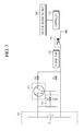
- FIG. 1 is a schematic circuit diagram showing an apparatus for balancing a battery pack having an overdischarge prevention function according to a first embodiment of the present invention.
- the apparatus for balancing a battery pack includes a balance signal relay unit 210, a discharge switching unit 220, a discharge resistor R d , a controller 230 and a voltage measuring unit 240.
- the balance signal relay unit 210, the discharge switching unit 220 and the discharge resistor R d are individually connected to a plurality of battery cells in parallel and discharge a battery cell that needs balancing such that a charging voltage of the battery cell comes to a target balancing voltage.
- the balance signal relay unit 210 is preferably a photo coupler that is electrically insulated from the controller 230 and performs an on/off operation according to a balance control signal output from the controller 230.
- the balance control signal is a pulse signal in which high-level signals and low-level signals are repeated at regular frequencies, or a high-level signal having a DC signal pattern. If the balance control signal is applied to the balance signal relay unit 210, the balance signal relay unit 210 is operated to initiate balancing of a battery cell V 1 .
- the photo coupler includes a light emitting element and a light receiving element, which are electrically insulated from each other.
- the light emitting element is connected to the controller 230 to generate a photo signal according to a balance control signal applied from the controller 230. If the balance control signal is a pulse signal with a regular frequency, the light emitting element generates a photo signal only in a high-level signal region. If a photo signal is generated from the light emitting element, the light receiving element relays the charging voltage of the battery cell V 1 to the discharge switching unit 220. Meanwhile, a resistor R 1 is interposed between the discharge switching unit 220 and the balance signal relay unit 210, and the resistor R 1 is an inherent resistor component of a circuit line connecting the discharge switching unit 220 and the balance signal relay unit 210.
- the discharge switching unit 220 is installed on a conductive line connected to both ends of the battery cell V 1 in parallel to switch the connection between the battery cell V 1 and the discharge resistor R d .
- the discharge switching unit 220 is an field effect transistor having a source terminal S, a drain terminal D and a gate terminal G.
- the discharge switching unit 220 and the battery cell V 1 configure a closed-loop circuit via the balance signal relay unit 210.
- a driving voltage for operating the discharge switching unit 220 is a charging voltage of the battery cell V 1 applied to the discharge switching unit 220 by the operation of the balance signal relay unit 210.
- the source terminal S of the discharge switching unit 220 is connected to one end of the battery cell V 1
- the drain terminal D is connected to the other end of the battery cell V 1 via the discharge resistor R d
- the gate terminal G is connected to the balance signal relay unit 210.
- the discharge switching unit 220 is operated as follows. If the controller 230 outputs a balance control signal, a charging voltage of the battery cell V 1 is applied as a driving voltage to the gate terminal G of the discharge switching unit 220. At this time, if the voltage applied to the gate terminal G is over an effective voltage level, the voltage V gs between the gate terminal and the source terminal becomes greater than a threshold voltage. Then, the discharge switching unit 220 is turned on to flow a discharging current between the source terminal and the drain terminal, and accordingly the discharge resistor R d discharges the charging voltage of the battery V 1 .
- the discharge switching unit 220 is turned off not to flow a discharging current between the source terminal and the drain terminal.
- the discharge resistor R d does not discharge the charging voltage of the battery cell V 1 any more.
- the effective voltage level is preferably a threshold voltage at which the battery cell V 1 comes to an overdischarged state.
- any person having ordinary skill in the art may easily select the discharge switching unit 220 having the overdischarge threshold voltage as an effective voltage level.
- the voltage V gs between the gate terminal and the source terminal becomes substantially identical to the charging voltage of the battery cell V 1 .
- the discharge switching unit 220 is automatically turned off to prevent the battery cell V 1 from being overdischarged. It is because the voltage V gs between the gate terminal and the source terminal is decreased lower than the effective voltage level if the battery cell V 1 comes to an overdischarged state.
- FIG. 2 is a schematic circuit diagram showing an apparatus for balancing a battery pack having an overdischarge prevention function according to a second embodiment of the present invention.
- the apparatus for balancing a battery pack according to the second embodiment of the present invention further includes a charge pump 250 and a voltage charging unit 260 in addition to the components of the battery pack balancing apparatus of the first embodiment, from which the balance signal relay unit 210 is excluded.
- the discharge switching unit 220, the charge pump 250, the voltage charging unit 260 and the discharge resistor R d are individually connected to a plurality of battery cells in parallel and discharge the battery cells until a charging voltage of a battery cell requiring balancing is discharged to a target balancing voltage.
- the voltage charging unit 260 includes a resistor R 2 and a capacitor C 2 .
- the resistor R 2 plays a role of discharging a voltage charged to the capacitor C 2 , and the capacitor C 2 applies the charged voltage to a gate terminal G of the discharge switching unit 220 as a driving voltage.
- a resistor R 1 is interposed between the voltage charging unit 260 and the charge pump 250, and the resistor is an inherent resistor component on a circuit line connecting the voltage charging unit 260 and the charge pump 250.
- the charge pump 250 performs a charge pumping operation if the controller 230 outputs a balance control signal. Also, the charge pump 250 includes a capacitor therein, so it electrically insulates the controller 230 from the battery cell V 1 .
- the charge pumping operation is performed only when the balance control signal output from the controller 230 is changed with a constant frequency, and the charge pumping operation is not performed if the balance control signal has a DC signal pattern.
- a circuit configuration of such a charge pump 250 having the above operation characteristics is well known in the art, so it is not described in detail here.
- a normal waveform of the balance control signal is preferably a signal pattern in which ON signals of a high level and OFF signals of a low level are repeated with regular frequencies.
- the balance control signal may have a DC signal waveform in which high-level signals or low-level signals are successively kept.
- the charge pump 250 pumps a charge to the capacitor C 2 included in the voltage charging unit 260 with a regular frequency if a balance control signal having a constant frequency is output from the controller 230. Then, voltages at both ends of the capacitor C 2 are increased, and a certain point of time, the driving voltage applied to the gate terminal G of the field effect transistor of the discharge switching unit 220 is increased over an effective voltage level at which the discharge switching unit 220 may be turned on. As a result, as the discharge switching unit 220 is turned on, the discharge resistor R d and the battery cell V 1 are connected in series to flow a discharging current, and according the battery cell V 1 is discharged to make a voltage balancing operation.
- an increased value of the voltage of the capacitor C 2 caused by the operation of the charge pump 250 (or, an increasing rate of the charging voltage) is preferably greater than a dropped value of the voltage of the capacitor C 2 caused by the discharge of the resistor R 2 (or, a decreasing rate of the charging voltage) such that the charging voltage of the capacitor C 2 may be kept over an effective voltage level that allows to turn on the discharge switching unit 220.
- This condition may be satisfied by controlling amplitude, duty ratio or frequency of the balance control signal.
- an abnormal signal pattern may be applied to the charge pump 250.
- a balance control signal having a DC pattern signal waveform, namely successive high-level or low-level signal may be applied to the charge pump.
- the charge pump 250 stops its charge-pumping operation due to inherent characteristics of the charge pump 250.
- the capacitor C 2 of the voltage charging unit 260 is not charged any more, so the charging voltage of the capacitor C 2 is lowered below the effective voltage level due to the discharge of the resistor R 2 , thereby turning off the discharge switching unit 220. From this point, the discharge of the battery cell V 1 is intercepted, and the discharge of the resistor R 2 is continued until the charging voltage of the capacitor C 2 becomes 0 (zero).
- the effective voltage level is determined depending on a charging voltage of the voltage charging unit 260.
- the effective voltage level at which current initiates to flow between the source terminal and the drain terminal of the field effect transistor of the discharge switching unit 220 is preferably smaller than a charging capacity of the voltage charging unit 260.
- an abnormal signal waveform particularly successive high-level signals, is applied to the charge pump 250 in a balance mode, it is possible to prevent the battery cell V 1 from being continuously discharged, and thus to prevent the battery cell V 1 from being overdischarged.
- a diode D1 may be selectively interposed between the charge pump 250 and the controller 230.
- the diode D1 plays a role of rectifying the balance control signal, thereby preventing noise signal from being introduced into the charge pump 250.
- the controller 230 periodically measures a charging voltage of a plurality of battery packs V 1 included in a battery pack 100 by means of the voltage measuring unit 240.
- a voltage measuring circuit is well known in the art, and not described in detail here.
- the controller 230 selects a battery cell that requires balancing, based on the measured voltage value of each battery cell. After that, the controller outputs a balance control signal to the balance signal relay unit 210 or the charge pump 250 corresponding to the selected battery cell such that the charging voltage of the battery cell is balanced according to the first and second embodiments.
- the balance signal relay unit 210 and the charge pump 250 are configured individually.
- the present invention is not limited thereto, but the balance signal relay unit 210 and the charge pump 250 may be configured together as shown in FIG. 3 that illustrates a third embodiment of the present invention.
- the balance signal relay unit 210 may be operated to apply a charging voltage of the battery cell V 1 to the charge pump 250 with the same frequency, and the charge pump 250 may be operated in the same way as in the second embodiment to balance a voltage of the battery cell V 1 .
- the controller 230 determines that a discharged battery cell reaches a target balancing voltage while periodically measuring a charging voltage of each battery cell, the controller 230 does not output a balance control signal any more to the balance signal relay unit 210 or the charge pump 250. Then, the balancing operation for the corresponding battery cell is ended.
- the controller 230 may include a separate memory (not shown) to accumulatively store voltage measurement values output from the voltage measuring unit 240, and also a program algorithm for realizing the charging voltage balancing operation of each battery cell may be recorded in the memory.
- the controller 230 may select a battery cell requiring balancing by, for example, averaging voltages of every battery cell and then choosing a battery cell having a voltage higher than the average voltage level as much as a certain value.
- a battery cell having a voltage over a certain value based on a battery cell having a lowest voltage may be selected as a subject for balancing.
- the present invention is not limited to such a battery cell selecting manner.
Landscapes
- Engineering & Computer Science (AREA)
- Chemical & Material Sciences (AREA)
- Chemical Kinetics & Catalysis (AREA)
- Electrochemistry (AREA)
- General Chemical & Material Sciences (AREA)
- Manufacturing & Machinery (AREA)
- Power Engineering (AREA)
- Charge And Discharge Circuits For Batteries Or The Like (AREA)
- Secondary Cells (AREA)
- Electric Propulsion And Braking For Vehicles (AREA)
- Protection Of Static Devices (AREA)
Abstract
Description
- The present invention relates to an apparatus for balancing a battery pack, and more particularly to an apparatus for balancing a battery pack with an overdischarge prevention function, which may prevent a cell from being overdischarged due to a failure of a control processor while balancing a charging voltage of each battery cell included in a battery pack.
- Generally, secondary batteries are classified into nickel-cadmium batteries, nickel-hydrogen batteries, lithium ion batteries, lithium ion polymer batteries and so on. Such secondary batteries are also classified into lithium-based batteries and nickel-hydrogen-based batteries. The lithium-based batteries are generally applied to small products such as digital cameras, P-DVD, MP3P, cellular phones, PDA, portable game devices, power tools and E-bikes, and the nickel-hydrogen-based batteries are generally applied to large products such as electric vehicles and hybrid vehicles, which require high power.
- Meanwhile, an electric or hybrid vehicle should operate a motor requiring high power in order to move. For this purpose, a battery employed in the electric or hybrid vehicle uses as a power source an electricity output from a battery pack in which a plurality of battery cells are connected in series.
- The plurality of battery cells included in the battery pack should keep their voltages uniformly in order to ensure stability, long life span and high power. An electric vehicle has a plurality of battery packs, each having a plurality of battery cells, and a battery management system (BMS) keeps each battery cell to a suitable voltage level while charging or discharging each battery cell of the battery pack. However, the plurality of battery cells may not be easily kept in an equivalent state due to various factors such as the change of internal impedance, so the BMS performs an operation for controlling the plurality of battery cells into an equivalent state.
- In order to control the battery cells in a high voltage battery pack to have uniform voltages, a semiconductor switch was conventionally used to selectively connect a discharge resistor (or, a Buck resistor) to a battery cell whose voltage is higher than an average voltage, thereby exhausting the energy possessed by the battery cell and thus decreasing a voltage difference between battery cells.
- In order to ensure safety while balancing the plurality of battery cells, if a voltage of a battery cell to be discharged is lowered to a certain voltage level, it is important to cut the connection between a discharge circuit and the corresponding battery cell. However, in some cases, the connection between the battery cell and the discharge circuit may not be cut at a proper time due to a failure of a control processor controlling the discharge of each battery cell or an error of a program algorithm. In this case, current is slightly discharged from the battery cell continuously, so the battery may come to an overdischarged state. If the battery cell is overdischarged, various dangers may occur. In particular, when coming to an overdischarged state, a lithium ion battery pack may cause serious problems, such as explosion.
- The present invention is designed to solve the problems of the prior art, and therefore it is an object of the present invention to provide an apparatus for balancing a battery pack having an overdischarge prevention function, which may prevent the battery pack from being continuously discharged due to a failure of a control processor while a discharge current is flowing to balance a charging voltage of battery cells.
- In order to accomplish the above object, the present invention provides an apparatus for balancing a battery pack having an overdischarge prevention function, which balances a charging voltage of each battery cell of a battery pack that includes a plurality of battery cells, the apparatus including a discharge resistor installed on a conductive line connected to both ends of a battery cell in parallel; a balance signal relay unit for relaying a charging voltage of the corresponding battery cell according to a balance control signal; and a discharge switching unit for receiving the charging voltage of the battery cell, relayed from the balance signal relay unit, as a driving voltage, the discharge switching unit connecting the battery cell to the discharge resistor to discharge the battery cell in case the driving voltage is over an effective voltage level.
- Preferably, the balance control signal is a pulse signal in which high-level signals and low-level signals are repeated at a predetermined frequency or a high-level signal of a DC signal pattern.
- Preferably, the balance signal relay unit is a photo coupler, and the balance signal relay unit includes a light emitting element and a light receiving element. The light emitting element receives the balance control signal to convert the high-level signal of the balance control signal into a photo signal, and the light receiving element is connected between the battery cell and the discharge switching unit and relays the charging voltage of the battery cell to the discharge switching unit when the photo signal is applied thereto from the light emitting element.
- Preferably, the discharge switching unit is a field effect transistor (FET), and the field effect transistor includes a source terminal connected to one of the battery cell, a drain terminal connected to the other end of the battery cell via the discharge resistor, and a gate terminal connected to the balance signal relay unit.
- Preferably, the effective voltage level at which current initiates to flow between the source terminal and the drain terminal of the field effect transistor is in a voltage level over an overdischarge threshold voltage of the battery cell.
- Preferably, the apparatus further includes a controller for measuring charging voltages of the plurality of battery cells included in the battery pack to select a battery cell that requires balancing, and applying a balance control signal to a balance signal relay unit connected to the selected battery cell to operate the balance signal relay unit.
- In another aspect of the present invention, there is also provided aAn apparatus for balancing a battery pack having an overdischarge prevention function, which balances a charging voltage of each battery cell of a battery pack that includes a plurality of battery cells, the apparatus including a discharge resistor installed on a conductive line connected to both ends of a battery cell in parallel; a charge pump for pumping charges only when a balance control signal of a predetermined frequency is input thereto; a discharge switching unit for connecting the battery cell to the discharge resistor when a driving voltage of an effective voltage level is applied thereto such that the battery cell is discharged; and a voltage charging unit for charging the pumped charges to apply the charging voltage as the driving voltage of the discharge switching unit.
- Preferably, the voltage charging unit includes a discharge resistor for discharging a charging voltage, and the charge pump pumps charges under the condition that an increasing rate of the charging voltage by the charge pumping process is greater than a decreasing rate of the charging voltage by the discharging process.
- Selectively, the apparatus may further include a diode provided on a conductive line through which the balance control signal is applied to the charge pump, the diode preventing noise from being introduced to the charge pump.
- As an alternative, the apparatus may further include a balance signal relay unit installed on a conductive line through which the balance control signal is applied to the charge pump, the balance signal relay unit periodically relaying high-level voltage signals and low-level voltage signals to the charge pump according to the balance control signal having a predetermined frequency output from a controller. At this time, the balance signal relay unit may be a photo coupler, and the balance signal relay unit may include a light emitting element and a light receiving element. The light emitting element receives the balance control signal to convert the high-level signal of the balance control signal into a photo signal, and the light receiving element is connected between the battery cell and the charge pump and relays the charging voltage of the battery cell to the charge pump at a predetermined frequency when the photo signal is applied thereto from the light emitting element.
- Preferably, the effective voltage level at which current initiates to flow between the source terminal and the drain terminal of the field effect transistor is smaller than a charging capacity of the voltage charging unit.
- According to the present invention, it is possible to prevent a battery cell from being overdischarged due to a failure of a control processor while balancing a charging voltage of battery cells. In addition, the control processor may be protected against an electric impact by electrically insulating the control processor from a discharge circuit that balances battery cells. Accordingly, it is possible to improve the safety of the battery pack.
- Other objects and aspects of the present invention will become apparent from the following description of embodiments with reference to the accompanying drawing in which:
-
FIG. 1 is a schematic circuit diagram showing an apparatus for balancing a battery pack having an overdischarge prevention function according to a first embodiment of the present invention; -
FIG. 2 is a schematic circuit diagram showing an apparatus for balancing a battery pack having an overdischarge prevention function according to a second embodiment of the present invention; and -
FIG. 3 is a schematic circuit diagram showing an apparatus for balancing a battery pack having an overdischarge prevention function according to a third embodiment of the present invention. - 100: battery pack 210: balance signal relay unit 220: discharge switching unit 230: controller 240: voltage measuring unit 250: charge pump 260: voltage charging unit
- Hereinafter, preferred embodiments of the present invention will be described in detail with reference to the accompanying drawings. Prior to the description, it should be understood that the terms used in the specification and the appended claims should not be construed as limited to general and dictionary meanings, but interpreted based on the meanings and concepts corresponding to technical aspects of the present invention on the basis of the principle that the inventor is allowed to define terms appropriately for the best explanation. Therefore, the description proposed herein is just a preferable example for the purpose of illustrations only, not intended to limit the scope of the invention, so it should be understood that other equivalents and modifications could be made thereto without departing from the spirit and scope of the invention.
-
FIG. 1 is a schematic circuit diagram showing an apparatus for balancing a battery pack having an overdischarge prevention function according to a first embodiment of the present invention. - Referring to
FIG. 1 , the apparatus for balancing a battery pack according to the first embodiment of the present invention includes a balancesignal relay unit 210, adischarge switching unit 220, a discharge resistor Rd, acontroller 230 and avoltage measuring unit 240. - The balance
signal relay unit 210, thedischarge switching unit 220 and the discharge resistor Rd are individually connected to a plurality of battery cells in parallel and discharge a battery cell that needs balancing such that a charging voltage of the battery cell comes to a target balancing voltage. - The balance
signal relay unit 210 is preferably a photo coupler that is electrically insulated from thecontroller 230 and performs an on/off operation according to a balance control signal output from thecontroller 230. The balance control signal is a pulse signal in which high-level signals and low-level signals are repeated at regular frequencies, or a high-level signal having a DC signal pattern. If the balance control signal is applied to the balancesignal relay unit 210, the balancesignal relay unit 210 is operated to initiate balancing of a battery cell V1. - The photo coupler includes a light emitting element and a light receiving element, which are electrically insulated from each other. The light emitting element is connected to the
controller 230 to generate a photo signal according to a balance control signal applied from thecontroller 230. If the balance control signal is a pulse signal with a regular frequency, the light emitting element generates a photo signal only in a high-level signal region. If a photo signal is generated from the light emitting element, the light receiving element relays the charging voltage of the battery cell V1 to thedischarge switching unit 220. Meanwhile, a resistor R1 is interposed between thedischarge switching unit 220 and the balancesignal relay unit 210, and the resistor R1 is an inherent resistor component of a circuit line connecting thedischarge switching unit 220 and the balancesignal relay unit 210. - The
discharge switching unit 220 is installed on a conductive line connected to both ends of the battery cell V1 in parallel to switch the connection between the battery cell V1 and the discharge resistor Rd. Preferably, thedischarge switching unit 220 is an field effect transistor having a source terminal S, a drain terminal D and a gate terminal G. - The
discharge switching unit 220 and the battery cell V1 configure a closed-loop circuit via the balancesignal relay unit 210. A driving voltage for operating thedischarge switching unit 220 is a charging voltage of the battery cell V1 applied to thedischarge switching unit 220 by the operation of the balancesignal relay unit 210. In other words, the source terminal S of thedischarge switching unit 220 is connected to one end of the battery cell V1, the drain terminal D is connected to the other end of the battery cell V1 via the discharge resistor Rd, and the gate terminal G is connected to the balancesignal relay unit 210. Thus, if the balancesignal relay unit 210 is operated, a voltage Vgs between the gate terminal and the source terminal of thedischarge switching unit 220 becomes substantially identical to the charging voltage of the battery cell V1. - The
discharge switching unit 220 is operated as follows. If thecontroller 230 outputs a balance control signal, a charging voltage of the battery cell V1 is applied as a driving voltage to the gate terminal G of thedischarge switching unit 220. At this time, if the voltage applied to the gate terminal G is over an effective voltage level, the voltage Vgs between the gate terminal and the source terminal becomes greater than a threshold voltage. Then, thedischarge switching unit 220 is turned on to flow a discharging current between the source terminal and the drain terminal, and accordingly the discharge resistor Rd discharges the charging voltage of the battery V1. Meanwhile, if the charging voltage of the battery cell V1 applied to the gate terminal G is smaller than an effective voltage level, the voltage Vgs between the gate terminal and the source terminal becomes smaller than a threshold voltage. Then, thedischarge switching unit 220 is turned off not to flow a discharging current between the source terminal and the drain terminal. As a result, the discharge resistor Rd does not discharge the charging voltage of the battery cell V1 any more. - In the first embodiment of the present invention, the effective voltage level is preferably a threshold voltage at which the battery cell V1 comes to an overdischarged state. Here, any person having ordinary skill in the art may easily select the
discharge switching unit 220 having the overdischarge threshold voltage as an effective voltage level. - According to the first embodiment of the present invention as explained above, in a balancing mode, the voltage Vgs between the gate terminal and the source terminal becomes substantially identical to the charging voltage of the battery cell V1. Thus, though the charging voltage of the battery cell V1 is continuously discharged due to the failure of the
controller 230, if the charging voltage of the battery cell V1 comes to an overdischarged state, thedischarge switching unit 220 is automatically turned off to prevent the battery cell V1 from being overdischarged. It is because the voltage Vgs between the gate terminal and the source terminal is decreased lower than the effective voltage level if the battery cell V1 comes to an overdischarged state. -
FIG. 2 is a schematic circuit diagram showing an apparatus for balancing a battery pack having an overdischarge prevention function according to a second embodiment of the present invention. - Referring to
FIG. 2 , the apparatus for balancing a battery pack according to the second embodiment of the present invention further includes acharge pump 250 and avoltage charging unit 260 in addition to the components of the battery pack balancing apparatus of the first embodiment, from which the balancesignal relay unit 210 is excluded. - The
discharge switching unit 220, thecharge pump 250, thevoltage charging unit 260 and the discharge resistor Rd are individually connected to a plurality of battery cells in parallel and discharge the battery cells until a charging voltage of a battery cell requiring balancing is discharged to a target balancing voltage. - The
voltage charging unit 260 includes a resistor R2 and a capacitor C2. The resistor R2 plays a role of discharging a voltage charged to the capacitor C2, and the capacitor C2 applies the charged voltage to a gate terminal G of thedischarge switching unit 220 as a driving voltage. - A resistor R1 is interposed between the
voltage charging unit 260 and thecharge pump 250, and the resistor is an inherent resistor component on a circuit line connecting thevoltage charging unit 260 and thecharge pump 250. - The
charge pump 250 performs a charge pumping operation if thecontroller 230 outputs a balance control signal. Also, thecharge pump 250 includes a capacitor therein, so it electrically insulates thecontroller 230 from the battery cell V1. - The charge pumping operation is performed only when the balance control signal output from the
controller 230 is changed with a constant frequency, and the charge pumping operation is not performed if the balance control signal has a DC signal pattern. A circuit configuration of such acharge pump 250 having the above operation characteristics is well known in the art, so it is not described in detail here. - In the second embodiment of the present invention, a normal waveform of the balance control signal is preferably a signal pattern in which ON signals of a high level and OFF signals of a low level are repeated with regular frequencies. However, if the controller is operated abnormally, the balance control signal may have a DC signal waveform in which high-level signals or low-level signals are successively kept.
- The
charge pump 250 pumps a charge to the capacitor C2 included in thevoltage charging unit 260 with a regular frequency if a balance control signal having a constant frequency is output from thecontroller 230. Then, voltages at both ends of the capacitor C2 are increased, and a certain point of time, the driving voltage applied to the gate terminal G of the field effect transistor of thedischarge switching unit 220 is increased over an effective voltage level at which thedischarge switching unit 220 may be turned on. As a result, as thedischarge switching unit 220 is turned on, the discharge resistor Rd and the battery cell V1 are connected in series to flow a discharging current, and according the battery cell V1 is discharged to make a voltage balancing operation. - While the voltage balancing operation is performed, the charges charged to the capacitor C2 of the
voltage charging unit 260 are continuously discharged through the resistor R2. Thus, for effective voltage balancing operation, an increased value of the voltage of the capacitor C2 caused by the operation of the charge pump 250 (or, an increasing rate of the charging voltage) is preferably greater than a dropped value of the voltage of the capacitor C2 caused by the discharge of the resistor R2 (or, a decreasing rate of the charging voltage) such that the charging voltage of the capacitor C2 may be kept over an effective voltage level that allows to turn on thedischarge switching unit 220. This condition may be satisfied by controlling amplitude, duty ratio or frequency of the balance control signal. - Meanwhile, if an abnormal balance control signal is output due to a failure of the
controller 230 or the like, an abnormal signal pattern may be applied to thecharge pump 250. For example, a balance control signal having a DC pattern signal waveform, namely successive high-level or low-level signal, may be applied to the charge pump. In this case, thecharge pump 250 stops its charge-pumping operation due to inherent characteristics of thecharge pump 250. Then, the capacitor C2 of thevoltage charging unit 260 is not charged any more, so the charging voltage of the capacitor C2 is lowered below the effective voltage level due to the discharge of the resistor R2, thereby turning off thedischarge switching unit 220. From this point, the discharge of the battery cell V1 is intercepted, and the discharge of the resistor R2 is continued until the charging voltage of the capacitor C2 becomes 0 (zero). - In the second embodiment of the present invention, the effective voltage level is determined depending on a charging voltage of the
voltage charging unit 260. In other words, the effective voltage level at which current initiates to flow between the source terminal and the drain terminal of the field effect transistor of thedischarge switching unit 220 is preferably smaller than a charging capacity of thevoltage charging unit 260. Here, it is apparent to those having ordinary skill in the art to select thedischarge switching unit 220 having a suitable effective voltage level according to a charging capacity of thevoltage charging unit 260. - According to the second embodiment, though an abnormal signal waveform, particularly successive high-level signals, is applied to the
charge pump 250 in a balance mode, it is possible to prevent the battery cell V1 from being continuously discharged, and thus to prevent the battery cell V1 from being overdischarged. - Meanwhile, a diode D1 may be selectively interposed between the
charge pump 250 and thecontroller 230. The diode D1 plays a role of rectifying the balance control signal, thereby preventing noise signal from being introduced into thecharge pump 250. - According to the present invention, the
controller 230 periodically measures a charging voltage of a plurality of battery packs V1 included in abattery pack 100 by means of thevoltage measuring unit 240. Such a voltage measuring circuit is well known in the art, and not described in detail here. Also, thecontroller 230 selects a battery cell that requires balancing, based on the measured voltage value of each battery cell. After that, the controller outputs a balance control signal to the balancesignal relay unit 210 or thecharge pump 250 corresponding to the selected battery cell such that the charging voltage of the battery cell is balanced according to the first and second embodiments. - Meanwhile, in the first and second embodiments, it has been explained that the balance
signal relay unit 210 and thecharge pump 250 are configured individually. However, the present invention is not limited thereto, but the balancesignal relay unit 210 and thecharge pump 250 may be configured together as shown inFIG. 3 that illustrates a third embodiment of the present invention. In this case, if a balance control signal with a constant frequency is output form thecontroller 230, the balancesignal relay unit 210 may be operated to apply a charging voltage of the battery cell V1 to thecharge pump 250 with the same frequency, and thecharge pump 250 may be operated in the same way as in the second embodiment to balance a voltage of the battery cell V1. - In addition, if the
controller 230 determines that a discharged battery cell reaches a target balancing voltage while periodically measuring a charging voltage of each battery cell, thecontroller 230 does not output a balance control signal any more to the balancesignal relay unit 210 or thecharge pump 250. Then, the balancing operation for the corresponding battery cell is ended. - The
controller 230 may include a separate memory (not shown) to accumulatively store voltage measurement values output from thevoltage measuring unit 240, and also a program algorithm for realizing the charging voltage balancing operation of each battery cell may be recorded in the memory. Thecontroller 230 may select a battery cell requiring balancing by, for example, averaging voltages of every battery cell and then choosing a battery cell having a voltage higher than the average voltage level as much as a certain value. As an alternative, a battery cell having a voltage over a certain value based on a battery cell having a lowest voltage may be selected as a subject for balancing. However, the present invention is not limited to such a battery cell selecting manner. - The present invention has been described in detail. However, it should be understood that the detailed description and specific examples, while indicating preferred embodiments of the invention, are given by way of illustration only, since various changes and modifications within the spirit and scope of the invention will become apparent to those skilled in the art from this detailed description.
Claims (19)
- An apparatus for balancing a battery pack having an overdischarge prevention function, which balances a charging voltage of each battery cell of a battery pack that includes a plurality of battery cells, the apparatus comprising:a discharge resistor installed on a conductive line connected to both ends of a battery cell in parallel;a balance signal relay unit for relaying a charging voltage of the corresponding battery cell according to a balance control signal; anda discharge switching unit for receiving the charging voltage of the battery cell, relayed from the balance signal relay unit, as a driving voltage, the discharge switching unit connecting the battery cell to the discharge resistor to discharge the battery cell in case the driving voltage is over an effective voltage level.
- The apparatus for balancing a battery pack having an overdischarge prevention function according to claim 1,
wherein the balance control signal is a pulse signal in which high-level signals and low-level signals are repeated at a predetermined frequency or a high-level signal of a DC signal pattern. - The apparatus for balancing a battery pack having an overdischarge prevention function according to claim 1,
wherein the balance signal relay unit is a photo coupler. - The apparatus for balancing a battery pack having an overdischarge prevention function according to claim 3,
wherein the balance signal relay unit includes a light emitting element and a light receiving element,
wherein the light emitting element receives the balance control signal to convert the high-level signal of the balance control signal into a photo signal, and
wherein the light receiving element is connected between the battery cell and the discharge switching unit and relays the charging voltage of the battery cell to the discharge switching unit when the photo signal is applied thereto from the light emitting element. - The apparatus for balancing a battery pack having an overdischarge prevention function according to claim 1,
wherein the discharge switching unit is a field effect transistor (FET). - The apparatus for balancing a battery pack having an overdischarge prevention function according to claim 5,
wherein the field effect transistor includes a source terminal connected to one of the battery cell, a drain terminal connected to the other end of the battery cell via the discharge resistor, and a gate terminal connected to the balance signal relay unit. - The apparatus for balancing a battery pack having an overdischarge prevention function according to claim 6,
wherein the effective voltage level at which current initiates to flow between the source terminal and the drain terminal of the field effect transistor is in a voltage level over an overdischarge threshold voltage of the battery cell. - The apparatus for balancing a battery pack having an overdischarge prevention function according to claim 1, further comprising a controller for measuring charging voltages of the plurality of battery cells included in the battery pack to select a battery cell that requires balancing, and applying a balance control signal to a balance signal relay unit connected to the selected battery cell to operate the balance signal relay unit.
- An apparatus for balancing a battery pack having an overdischarge prevention function, which balances a charging voltage of each battery cell of a battery pack that includes a plurality of battery cells, the apparatus comprising:a discharge resistor installed on a conductive line connected to both ends of a battery cell in parallel;a charge pump for pumping charges only when a balance control signal of a predetermined frequency is input thereto;a discharge switching unit for connecting the battery cell to the discharge resistor when a driving voltage of an effective voltage level is applied thereto such that the battery cell is discharged; anda voltage charging unit for charging the pumped charges to apply the charging voltage as the driving voltage of the discharge switching unit.
- The apparatus for balancing a battery pack having an overdischarge prevention function according to claim 9,
wherein the voltage charging unit includes a discharge resistor for discharging a charging voltage, and
wherein the charge pump pumps charges under the condition that an increasing rate of the charging voltage by the charge pumping process is greater than a decreasing rate of the charging voltage by the discharging process. - The apparatus for balancing a battery pack having an overdischarge prevention function according to claim 9,
wherein the balance control signal is a pulse signal in which high-level signals and low-level signals are repeated at a predetermined frequency. - The apparatus for balancing a battery pack having an overdischarge prevention function according to claim 9, further comprising a diode provided on a conductive line through which the balance control signal is applied to the charge pump, the diode preventing noise from being introduced to the charge pump.
- The apparatus for balancing a battery pack having an overdischarge prevention function according to claim 9, further comprising a balance signal relay unit installed on a conductive line through which the balance control signal is applied to the charge pump, the balance signal relay unit periodically relaying high-level voltage signals and low-level voltage signals to the charge pump according to the balance control signal having a predetermined frequency output from a controller.
- The apparatus for balancing a battery pack having an overdischarge prevention function according to claim 13,
wherein the balance signal relay unit is a photo coupler. - The apparatus for balancing a battery pack having an overdischarge prevention function according to claim 14,
wherein the balance signal relay unit includes a light emitting element and a light receiving element,
wherein the light emitting element receives the balance control signal to convert the high-level signal of the balance control signal into a photo signal, and
wherein the light receiving element is connected between the battery cell and the charge pump, and the light receiving element relays the charging voltage of the battery cell to the charge pump at a predetermined frequency when the photo signal is applied thereto from the light emitting element. - The apparatus for balancing a battery pack having an overdischarge prevention function according to claim 9,
wherein the discharge switching unit is a field effect transistor (FET). - The apparatus for balancing a battery pack having an overdischarge prevention function according to claim 16,
wherein the field effect transistor includes a source terminal connected to one of the battery cell, a drain terminal connected to the other end of the battery cell via the discharge resistor, and a gate terminal connected to the voltage charging unit. - The apparatus for balancing a battery pack having an overdischarge prevention function according to claim 17,
wherein the effective voltage level at which current initiates to flow between the source terminal and the drain terminal of the field effect transistor is smaller than a charging capacity of the voltage charging unit. - The apparatus for balancing a battery pack having an overdischarge prevention function according to claim 9, further comprising a controller for measuring charging voltages of the plurality of battery cells included in the battery pack to select a battery cell that requires balancing, and applying the balance control signal to a charge pump connected to the selected battery cell to operate the charge pump.
Applications Claiming Priority (4)
| Application Number | Priority Date | Filing Date | Title |
|---|---|---|---|
| KR20080049807 | 2008-05-28 | ||
| KR20090045588 | 2009-05-25 | ||
| KR1020090046650A KR101091352B1 (en) | 2008-05-28 | 2009-05-27 | Battery pack balancing device with overdischarge protection |
| PCT/KR2009/002843 WO2009145577A2 (en) | 2008-05-28 | 2009-05-28 | Balancing apparatus for battery pack with over-discharge protection function |
Publications (3)
| Publication Number | Publication Date |
|---|---|
| EP2296250A2 true EP2296250A2 (en) | 2011-03-16 |
| EP2296250A4 EP2296250A4 (en) | 2012-08-08 |
| EP2296250B1 EP2296250B1 (en) | 2015-07-29 |
Family
ID=41685956
Family Applications (1)
| Application Number | Title | Priority Date | Filing Date |
|---|---|---|---|
| EP09755042.0A Active EP2296250B1 (en) | 2008-05-28 | 2009-05-28 | Balancing apparatus for battery pack with over-discharge protection function |
Country Status (6)
| Country | Link |
|---|---|
| US (1) | US8004238B2 (en) |
| EP (1) | EP2296250B1 (en) |
| JP (2) | JP5536044B2 (en) |
| KR (1) | KR101091352B1 (en) |
| CN (1) | CN102047526B (en) |
| WO (1) | WO2009145577A2 (en) |
Cited By (1)
| Publication number | Priority date | Publication date | Assignee | Title |
|---|---|---|---|---|
| US8901888B1 (en) | 2013-07-16 | 2014-12-02 | Christopher V. Beckman | Batteries for optimizing output and charge balance with adjustable, exportable and addressable characteristics |
Families Citing this family (41)
| Publication number | Priority date | Publication date | Assignee | Title |
|---|---|---|---|---|
| US9142951B2 (en) | 2009-07-28 | 2015-09-22 | Stmicroelectronics (Rousset) Sas | Electronic device for protecting against a polarity reversal of a DC power supply voltage, and its application to motor vehicles |
| FR2948828B1 (en) * | 2009-07-28 | 2011-09-30 | St Microelectronics Rousset | ELECTRONIC DEVICE FOR PROTECTION AGAINST A POLARITY INVERSION OF A CONTINUOUS POWER SUPPLY VOLTAGE, AND APPLICATION TO THE AUTOMOTIVE DOMAIN |
| CN102823104B (en) * | 2010-02-05 | 2016-05-11 | 法国原子能源和替代能源委员会 | Charge equalization system for batteries |
| US8865328B2 (en) | 2010-06-09 | 2014-10-21 | Samsung Sdi Co., Ltd. | Battery protecting circuit, method of controlling the same, and battery pack |
| KR101147168B1 (en) * | 2010-09-09 | 2012-05-25 | (주)이미지스테크놀로지 | System for control cell balance of battery pack using eq cell and method thereof |
| US20120086401A1 (en) * | 2010-10-07 | 2012-04-12 | Intersil Americas Inc. | Cell balancing circuit for use in a multi-cell battery system |
| KR101217074B1 (en) | 2011-02-21 | 2012-12-31 | 로베르트 보쉬 게엠베하 | Battery management system |
| JP5918961B2 (en) * | 2011-10-07 | 2016-05-18 | 株式会社ケーヒン | Cell balance control device |
| US9071056B2 (en) | 2011-11-04 | 2015-06-30 | Samsung Sdi Co., Ltd. | Apparatus and method for managing battery cell, and energy storage system |
| WO2013153650A1 (en) * | 2012-04-12 | 2013-10-17 | 三菱電機株式会社 | Discharging device for electricity storage device |
| US9018865B2 (en) * | 2012-04-30 | 2015-04-28 | GM Global Technology Operations LLC | Passive high-voltage DC bus discharge circuit for a vehicle |
| US9315113B2 (en) | 2012-12-21 | 2016-04-19 | Ample Inc. | Electric vehicle battery systems with exchangeable parallel electric vehicle battery modules |
| EP2950420B1 (en) * | 2013-01-25 | 2019-07-24 | Hitachi Automotive Systems, Ltd. | Cell controller and cell monitoring device |
| DE102013001466B4 (en) * | 2013-01-29 | 2019-04-25 | Audi Ag | Battery with balancing function and motor vehicle |
| US9276415B2 (en) | 2013-09-18 | 2016-03-01 | Go-Tech Energy Co. Ltd. | Charging station having battery cell balancing system |
| KR101711706B1 (en) * | 2014-11-20 | 2017-03-02 | 주식회사 엘지화학 | Common Mode Noise Simulator |
| CN106033905B (en) * | 2015-03-20 | 2018-10-23 | 李莉 | A kind of battery pack control unit, control system and control method |
| KR102222119B1 (en) | 2016-08-11 | 2021-03-03 | 삼성에스디아이 주식회사 | battery pack |
| US10112487B1 (en) * | 2017-04-18 | 2018-10-30 | Ford Global Technologies, Llc | System and method of maintaining high voltage battery charging with detected auxiliary battery fault |
| CN109904885A (en) * | 2017-12-08 | 2019-06-18 | 神讯电脑(昆山)有限公司 | Battery pack pressure difference automatic balancing device |
| KR102446380B1 (en) * | 2018-02-27 | 2022-09-21 | 삼성에스디아이 주식회사 | battery management system |
| US11451072B2 (en) | 2018-07-10 | 2022-09-20 | Samsung Sdi Co., Ltd. | Battery system |
| KR102443667B1 (en) * | 2018-10-26 | 2022-09-14 | 주식회사 엘지에너지솔루션 | balancing apparatus, and battery management system and battery pack including the same |
| KR102744523B1 (en) * | 2019-01-10 | 2024-12-18 | 주식회사 엘지에너지솔루션 | Controller ic, battery controller circuit comprising the controller ic, and battery pack comprising the battery controller circuit |
| CN112349973A (en) * | 2019-08-07 | 2021-02-09 | 北京小米移动软件有限公司 | Battery module, charging method and device, electronic device and readable storage medium |
| US11476690B2 (en) | 2019-10-25 | 2022-10-18 | Samsung Sdi Co., Ltd. | Power supply system |
| US11262408B2 (en) | 2020-02-24 | 2022-03-01 | Ford Global Technologies, Llc | Vehicle traction battery over-discharge diagnosing method and assembly |
| US11411407B1 (en) | 2021-02-24 | 2022-08-09 | Inventus Power, Inc. | Large-format battery management systems with gateway PCBA |
| US11404885B1 (en) | 2021-02-24 | 2022-08-02 | Inventus Power, Inc. | Large-format battery management systems with gateway PCBA |
| US11588334B2 (en) | 2020-06-02 | 2023-02-21 | Inventus Power, Inc. | Broadcast of discharge current based on state-of-health imbalance between battery packs |
| US11552479B2 (en) | 2020-06-02 | 2023-01-10 | Inventus Power, Inc. | Battery charge balancing circuit for series connections |
| US12301031B1 (en) | 2020-06-02 | 2025-05-13 | Inventus Power, Inc. | Large-format battery management systems with gateway PCBA |
| WO2021243550A1 (en) | 2020-06-02 | 2021-12-09 | Inventus Power, Inc. | Large-format battery management system |
| US11476677B2 (en) | 2020-06-02 | 2022-10-18 | Inventus Power, Inc. | Battery pack charge cell balancing |
| JP7565383B2 (en) * | 2020-06-02 | 2024-10-10 | ザ・ノコ・カンパニー | Lithium-ion battery cell balancing system and method, and battery charging device with lithium-ion battery cell balancing |
| US12224603B2 (en) | 2020-06-02 | 2025-02-11 | Inventus Power, Inc. | Mode-based disabling of communication bus of a battery management system |
| US11594892B2 (en) | 2020-06-02 | 2023-02-28 | Inventus Power, Inc. | Battery pack with series or parallel identification signal |
| US11509144B2 (en) | 2020-06-02 | 2022-11-22 | Inventus Power, Inc. | Large-format battery management system with in-rush current protection for master-slave battery packs |
| US11245268B1 (en) | 2020-07-24 | 2022-02-08 | Inventus Power, Inc. | Mode-based disabling of communiction bus of a battery management system |
| KR102367800B1 (en) * | 2021-11-30 | 2022-02-25 | (주)엠텍정보기술 | battery balancing device |
| US12286018B2 (en) | 2023-03-20 | 2025-04-29 | Ample Inc. | Over-voltage protection circuit for electric vehicles |
Family Cites Families (20)
| Publication number | Priority date | Publication date | Assignee | Title |
|---|---|---|---|---|
| US4617496A (en) * | 1984-05-30 | 1986-10-14 | Samodovitz Arthur J | Warm-up circuit with timed shut-off of the warm-up current |
| JP3279071B2 (en) * | 1994-06-29 | 2002-04-30 | 日産自動車株式会社 | Battery pack charging device |
| GB9605830D0 (en) * | 1996-03-20 | 1996-05-22 | Atomic Energy Authority Uk | Cell overcharge prevention |
| JP3692737B2 (en) * | 1997-11-07 | 2005-09-07 | 株式会社デンソー | Charge pump circuit |
| DE19845673A1 (en) * | 1998-10-05 | 2000-04-20 | Fahrzeugklimaregelung Gmbh | Protection circuit for a power field effect transistor (FET) |
| JP2000228830A (en) * | 1999-02-05 | 2000-08-15 | Toyama Prefecture | Method and apparatus for charging secondary battery |
| JP3610823B2 (en) * | 1999-04-27 | 2005-01-19 | 新神戸電機株式会社 | Module battery control device, module battery unit, and module battery control method |
| JP3615500B2 (en) * | 2001-06-22 | 2005-02-02 | 三洋電機株式会社 | Battery charge rate adjustment circuit |
| JP2003066090A (en) * | 2001-08-29 | 2003-03-05 | Omron Corp | Earth leakage detection device |
| KR20030021665A (en) * | 2001-09-07 | 2003-03-15 | 엘지이노텍 주식회사 | Charging and discharging appratus of battery |
| JP2004248348A (en) * | 2003-02-10 | 2004-09-02 | Denso Corp | Battery pack discharging device |
| US6873134B2 (en) * | 2003-07-21 | 2005-03-29 | The Boeing Company | Autonomous battery cell balancing system with integrated voltage monitoring |
| JP2005130664A (en) * | 2003-10-27 | 2005-05-19 | Sony Corp | Battery pack |
| US7456614B2 (en) * | 2003-10-27 | 2008-11-25 | Sony Corporation | Battery pack |
| JP2005160169A (en) * | 2003-11-21 | 2005-06-16 | Texas Instr Japan Ltd | Battery protection circuit |
| DE202005010858U1 (en) * | 2005-05-21 | 2006-09-28 | Diehl Luftfahrt Elektronik Gmbh | Device for monitoring and controlling a plurality of series connected capacities |
| JP4597044B2 (en) * | 2005-12-09 | 2010-12-15 | 株式会社リコー | Backflow prevention circuit |
| JP4895694B2 (en) * | 2006-06-08 | 2012-03-14 | ルネサスエレクトロニクス株式会社 | Power circuit |
| KR100905663B1 (en) * | 2006-07-13 | 2009-06-30 | 주식회사 엘지화학 | Circuit operating current balancing device and method of a battery device |
| KR100778414B1 (en) * | 2006-10-12 | 2007-11-22 | 삼성에스디아이 주식회사 | Battery Management System and Its Driving Method |
-
2009
- 2009-05-27 KR KR1020090046650A patent/KR101091352B1/en active Active
- 2009-05-28 EP EP09755042.0A patent/EP2296250B1/en active Active
- 2009-05-28 CN CN2009801194054A patent/CN102047526B/en active Active
- 2009-05-28 JP JP2011511513A patent/JP5536044B2/en active Active
- 2009-05-28 WO PCT/KR2009/002843 patent/WO2009145577A2/en not_active Ceased
-
2010
- 2010-06-15 US US12/815,780 patent/US8004238B2/en active Active
-
2013
- 2013-07-29 JP JP2013156925A patent/JP2014003892A/en active Pending
Cited By (1)
| Publication number | Priority date | Publication date | Assignee | Title |
|---|---|---|---|---|
| US8901888B1 (en) | 2013-07-16 | 2014-12-02 | Christopher V. Beckman | Batteries for optimizing output and charge balance with adjustable, exportable and addressable characteristics |
Also Published As
| Publication number | Publication date |
|---|---|
| EP2296250A4 (en) | 2012-08-08 |
| EP2296250B1 (en) | 2015-07-29 |
| US8004238B2 (en) | 2011-08-23 |
| US20100253287A1 (en) | 2010-10-07 |
| CN102047526B (en) | 2013-11-06 |
| JP5536044B2 (en) | 2014-07-02 |
| CN102047526A (en) | 2011-05-04 |
| WO2009145577A3 (en) | 2010-03-11 |
| JP2011523337A (en) | 2011-08-04 |
| KR101091352B1 (en) | 2011-12-07 |
| WO2009145577A2 (en) | 2009-12-03 |
| KR20090123821A (en) | 2009-12-02 |
| JP2014003892A (en) | 2014-01-09 |
Similar Documents
| Publication | Publication Date | Title |
|---|---|---|
| US8004238B2 (en) | Apparatus for balancing of battery pack having function of prevention of over-discharge | |
| US11011920B2 (en) | Energy storage apparatus for engine start-up, method for controlling the same, and vehicle | |
| US11101667B2 (en) | Energy storage apparatus and charge control method for the same | |
| US10840722B2 (en) | Battery control device | |
| JP5349021B2 (en) | Battery system | |
| EP2083494B1 (en) | Abnormality detecting device for storage element, abnormality detecting method for storage element, abnormality detecting program for storage element, and computer-readable recording medium storing abnormality detecting program | |
| KR100998304B1 (en) | Battery pack and its charging method | |
| US9682673B2 (en) | Vehicle power source device and vehicle equipped with the power source device | |
| US10348107B2 (en) | Battery device | |
| EP2221937A2 (en) | Built-in charge circuit for secondary battery and secondary battery with the built-in charge circuit | |
| JP5301036B2 (en) | On-board electric system for vehicle and control device for on-board electric system | |
| KR101312263B1 (en) | Vehicle and method for controlling the same | |
| KR20100020477A (en) | Battery pack and battery system | |
| US20140159664A1 (en) | Method of manufacturing battery pack and battery pack | |
| KR20150098555A (en) | Apparatus, system and method for preventing damage of battery rack using current measurement | |
| KR20120010061A (en) | Battery pack and its charge / discharge control method | |
| KR102020044B1 (en) | Battery charging system, and method for controlling maximum capacity charging in battery module using the same | |
| KR20240014216A (en) | Method and apparatus for detecting internal short circuit of battery | |
| KR102538244B1 (en) | Device and method for preventing battery abnormalities using diodes | |
| US20240140268A1 (en) | Charging amount regulating device, and vehicle | |
| KR20170025629A (en) | An apparatus of algorism for charging and recharging numerous battery | |
| US20250192593A1 (en) | Battery pack group and driving method thereof | |
| US20140191725A1 (en) | Method and device for equilibrating electric accumulator batteries | |
| JP2023008149A (en) | Abnormality detection method for power storage device and assembled battery | |
| JP2004235100A (en) | Battery pack |
Legal Events
| Date | Code | Title | Description |
|---|---|---|---|
| PUAI | Public reference made under article 153(3) epc to a published international application that has entered the european phase |
Free format text: ORIGINAL CODE: 0009012 |
|
| 17P | Request for examination filed |
Effective date: 20101215 |
|
| AK | Designated contracting states |
Kind code of ref document: A2 Designated state(s): AT BE BG CH CY CZ DE DK EE ES FI FR GB GR HR HU IE IS IT LI LT LU LV MC MK MT NL NO PL PT RO SE SI SK TR |
|
| AX | Request for extension of the european patent |
Extension state: AL BA RS |
|
| DAX | Request for extension of the european patent (deleted) | ||
| A4 | Supplementary search report drawn up and despatched |
Effective date: 20120705 |
|
| RIC1 | Information provided on ipc code assigned before grant |
Ipc: H01M 2/34 20060101ALI20120629BHEP Ipc: H01M 10/44 20060101ALI20120629BHEP Ipc: H02J 7/00 20060101AFI20120629BHEP |
|
| 17Q | First examination report despatched |
Effective date: 20130523 |
|
| REG | Reference to a national code |
Ref country code: DE Ref legal event code: R079 Ref document number: 602009032530 Country of ref document: DE Free format text: PREVIOUS MAIN CLASS: H02J0007040000 Ipc: H01M0002340000 |
|
| RIC1 | Information provided on ipc code assigned before grant |
Ipc: H02J 7/00 20060101ALI20150210BHEP Ipc: H01M 10/0525 20100101ALN20150210BHEP Ipc: H01M 2/34 20060101AFI20150210BHEP Ipc: H01M 10/44 20060101ALI20150210BHEP |
|
| GRAP | Despatch of communication of intention to grant a patent |
Free format text: ORIGINAL CODE: EPIDOSNIGR1 |
|
| INTG | Intention to grant announced |
Effective date: 20150401 |
|
| GRAS | Grant fee paid |
Free format text: ORIGINAL CODE: EPIDOSNIGR3 |
|
| GRAA | (expected) grant |
Free format text: ORIGINAL CODE: 0009210 |
|
| AK | Designated contracting states |
Kind code of ref document: B1 Designated state(s): AT BE BG CH CY CZ DE DK EE ES FI FR GB GR HR HU IE IS IT LI LT LU LV MC MK MT NL NO PL PT RO SE SI SK TR |
|
| REG | Reference to a national code |
Ref country code: GB Ref legal event code: FG4D |
|
| REG | Reference to a national code |
Ref country code: CH Ref legal event code: EP |
|
| REG | Reference to a national code |
Ref country code: AT Ref legal event code: REF Ref document number: 739912 Country of ref document: AT Kind code of ref document: T Effective date: 20150815 |
|
| REG | Reference to a national code |
Ref country code: IE Ref legal event code: FG4D |
|
| REG | Reference to a national code |
Ref country code: DE Ref legal event code: R096 Ref document number: 602009032530 Country of ref document: DE |
|
| REG | Reference to a national code |
Ref country code: SE Ref legal event code: TRGR |
|
| REG | Reference to a national code |
Ref country code: AT Ref legal event code: MK05 Ref document number: 739912 Country of ref document: AT Kind code of ref document: T Effective date: 20150729 |
|
| REG | Reference to a national code |
Ref country code: LT Ref legal event code: MG4D |
|
| REG | Reference to a national code |
Ref country code: NL Ref legal event code: MP Effective date: 20150729 |
|
| PG25 | Lapsed in a contracting state [announced via postgrant information from national office to epo] |
Ref country code: LT Free format text: LAPSE BECAUSE OF FAILURE TO SUBMIT A TRANSLATION OF THE DESCRIPTION OR TO PAY THE FEE WITHIN THE PRESCRIBED TIME-LIMIT Effective date: 20150729 Ref country code: LV Free format text: LAPSE BECAUSE OF FAILURE TO SUBMIT A TRANSLATION OF THE DESCRIPTION OR TO PAY THE FEE WITHIN THE PRESCRIBED TIME-LIMIT Effective date: 20150729 Ref country code: FI Free format text: LAPSE BECAUSE OF FAILURE TO SUBMIT A TRANSLATION OF THE DESCRIPTION OR TO PAY THE FEE WITHIN THE PRESCRIBED TIME-LIMIT Effective date: 20150729 Ref country code: NO Free format text: LAPSE BECAUSE OF FAILURE TO SUBMIT A TRANSLATION OF THE DESCRIPTION OR TO PAY THE FEE WITHIN THE PRESCRIBED TIME-LIMIT Effective date: 20151029 Ref country code: GR Free format text: LAPSE BECAUSE OF FAILURE TO SUBMIT A TRANSLATION OF THE DESCRIPTION OR TO PAY THE FEE WITHIN THE PRESCRIBED TIME-LIMIT Effective date: 20151030 |
|
| PG25 | Lapsed in a contracting state [announced via postgrant information from national office to epo] |
Ref country code: PT Free format text: LAPSE BECAUSE OF FAILURE TO SUBMIT A TRANSLATION OF THE DESCRIPTION OR TO PAY THE FEE WITHIN THE PRESCRIBED TIME-LIMIT Effective date: 20151130 Ref country code: HR Free format text: LAPSE BECAUSE OF FAILURE TO SUBMIT A TRANSLATION OF THE DESCRIPTION OR TO PAY THE FEE WITHIN THE PRESCRIBED TIME-LIMIT Effective date: 20150729 Ref country code: AT Free format text: LAPSE BECAUSE OF FAILURE TO SUBMIT A TRANSLATION OF THE DESCRIPTION OR TO PAY THE FEE WITHIN THE PRESCRIBED TIME-LIMIT Effective date: 20150729 Ref country code: ES Free format text: LAPSE BECAUSE OF FAILURE TO SUBMIT A TRANSLATION OF THE DESCRIPTION OR TO PAY THE FEE WITHIN THE PRESCRIBED TIME-LIMIT Effective date: 20150729 Ref country code: PL Free format text: LAPSE BECAUSE OF FAILURE TO SUBMIT A TRANSLATION OF THE DESCRIPTION OR TO PAY THE FEE WITHIN THE PRESCRIBED TIME-LIMIT Effective date: 20150729 Ref country code: IS Free format text: LAPSE BECAUSE OF FAILURE TO SUBMIT A TRANSLATION OF THE DESCRIPTION OR TO PAY THE FEE WITHIN THE PRESCRIBED TIME-LIMIT Effective date: 20151129 |
|
| PG25 | Lapsed in a contracting state [announced via postgrant information from national office to epo] |
Ref country code: NL Free format text: LAPSE BECAUSE OF FAILURE TO SUBMIT A TRANSLATION OF THE DESCRIPTION OR TO PAY THE FEE WITHIN THE PRESCRIBED TIME-LIMIT Effective date: 20150729 |
|
| REG | Reference to a national code |
Ref country code: FR Ref legal event code: PLFP Year of fee payment: 8 |
|
| PG25 | Lapsed in a contracting state [announced via postgrant information from national office to epo] |
Ref country code: SK Free format text: LAPSE BECAUSE OF FAILURE TO SUBMIT A TRANSLATION OF THE DESCRIPTION OR TO PAY THE FEE WITHIN THE PRESCRIBED TIME-LIMIT Effective date: 20150729 Ref country code: EE Free format text: LAPSE BECAUSE OF FAILURE TO SUBMIT A TRANSLATION OF THE DESCRIPTION OR TO PAY THE FEE WITHIN THE PRESCRIBED TIME-LIMIT Effective date: 20150729 Ref country code: CZ Free format text: LAPSE BECAUSE OF FAILURE TO SUBMIT A TRANSLATION OF THE DESCRIPTION OR TO PAY THE FEE WITHIN THE PRESCRIBED TIME-LIMIT Effective date: 20150729 Ref country code: DK Free format text: LAPSE BECAUSE OF FAILURE TO SUBMIT A TRANSLATION OF THE DESCRIPTION OR TO PAY THE FEE WITHIN THE PRESCRIBED TIME-LIMIT Effective date: 20150729 |
|
| REG | Reference to a national code |
Ref country code: DE Ref legal event code: R097 Ref document number: 602009032530 Country of ref document: DE |
|
| PG25 | Lapsed in a contracting state [announced via postgrant information from national office to epo] |
Ref country code: RO Free format text: LAPSE BECAUSE OF FAILURE TO SUBMIT A TRANSLATION OF THE DESCRIPTION OR TO PAY THE FEE WITHIN THE PRESCRIBED TIME-LIMIT Effective date: 20150729 |
|
| PLBE | No opposition filed within time limit |
Free format text: ORIGINAL CODE: 0009261 |
|
| STAA | Information on the status of an ep patent application or granted ep patent |
Free format text: STATUS: NO OPPOSITION FILED WITHIN TIME LIMIT |
|
| 26N | No opposition filed |
Effective date: 20160502 |
|
| PG25 | Lapsed in a contracting state [announced via postgrant information from national office to epo] |
Ref country code: SI Free format text: LAPSE BECAUSE OF FAILURE TO SUBMIT A TRANSLATION OF THE DESCRIPTION OR TO PAY THE FEE WITHIN THE PRESCRIBED TIME-LIMIT Effective date: 20150729 Ref country code: BE Free format text: LAPSE BECAUSE OF NON-PAYMENT OF DUE FEES Effective date: 20160531 |
|
| PG25 | Lapsed in a contracting state [announced via postgrant information from national office to epo] |
Ref country code: BE Free format text: LAPSE BECAUSE OF FAILURE TO SUBMIT A TRANSLATION OF THE DESCRIPTION OR TO PAY THE FEE WITHIN THE PRESCRIBED TIME-LIMIT Effective date: 20150729 Ref country code: LU Free format text: LAPSE BECAUSE OF FAILURE TO SUBMIT A TRANSLATION OF THE DESCRIPTION OR TO PAY THE FEE WITHIN THE PRESCRIBED TIME-LIMIT Effective date: 20160528 |
|
| REG | Reference to a national code |
Ref country code: CH Ref legal event code: PL |
|
| GBPC | Gb: european patent ceased through non-payment of renewal fee |
Effective date: 20160528 |
|
| PG25 | Lapsed in a contracting state [announced via postgrant information from national office to epo] |
Ref country code: LI Free format text: LAPSE BECAUSE OF NON-PAYMENT OF DUE FEES Effective date: 20160531 Ref country code: CH Free format text: LAPSE BECAUSE OF NON-PAYMENT OF DUE FEES Effective date: 20160531 |
|
| REG | Reference to a national code |
Ref country code: IE Ref legal event code: MM4A |
|
| REG | Reference to a national code |
Ref country code: FR Ref legal event code: PLFP Year of fee payment: 9 |
|
| PG25 | Lapsed in a contracting state [announced via postgrant information from national office to epo] |
Ref country code: IE Free format text: LAPSE BECAUSE OF NON-PAYMENT OF DUE FEES Effective date: 20160528 Ref country code: GB Free format text: LAPSE BECAUSE OF NON-PAYMENT OF DUE FEES Effective date: 20160528 |
|
| REG | Reference to a national code |
Ref country code: FR Ref legal event code: PLFP Year of fee payment: 10 |
|
| PG25 | Lapsed in a contracting state [announced via postgrant information from national office to epo] |
Ref country code: CY Free format text: LAPSE BECAUSE OF FAILURE TO SUBMIT A TRANSLATION OF THE DESCRIPTION OR TO PAY THE FEE WITHIN THE PRESCRIBED TIME-LIMIT Effective date: 20150729 Ref country code: HU Free format text: LAPSE BECAUSE OF FAILURE TO SUBMIT A TRANSLATION OF THE DESCRIPTION OR TO PAY THE FEE WITHIN THE PRESCRIBED TIME-LIMIT; INVALID AB INITIO Effective date: 20090528 |
|
| PG25 | Lapsed in a contracting state [announced via postgrant information from national office to epo] |
Ref country code: MT Free format text: LAPSE BECAUSE OF NON-PAYMENT OF DUE FEES Effective date: 20160531 Ref country code: MK Free format text: LAPSE BECAUSE OF FAILURE TO SUBMIT A TRANSLATION OF THE DESCRIPTION OR TO PAY THE FEE WITHIN THE PRESCRIBED TIME-LIMIT Effective date: 20150729 Ref country code: MC Free format text: LAPSE BECAUSE OF FAILURE TO SUBMIT A TRANSLATION OF THE DESCRIPTION OR TO PAY THE FEE WITHIN THE PRESCRIBED TIME-LIMIT Effective date: 20150729 Ref country code: TR Free format text: LAPSE BECAUSE OF FAILURE TO SUBMIT A TRANSLATION OF THE DESCRIPTION OR TO PAY THE FEE WITHIN THE PRESCRIBED TIME-LIMIT Effective date: 20150729 |
|
| PG25 | Lapsed in a contracting state [announced via postgrant information from national office to epo] |
Ref country code: BG Free format text: LAPSE BECAUSE OF FAILURE TO SUBMIT A TRANSLATION OF THE DESCRIPTION OR TO PAY THE FEE WITHIN THE PRESCRIBED TIME-LIMIT Effective date: 20150729 |
|
| REG | Reference to a national code |
Ref country code: DE Ref legal event code: R079 Ref document number: 602009032530 Country of ref document: DE Free format text: PREVIOUS MAIN CLASS: H01M0002340000 Ipc: H01M0050572000 |
|
| REG | Reference to a national code |
Ref country code: DE Ref legal event code: R081 Ref document number: 602009032530 Country of ref document: DE Owner name: LG ENERGY SOLUTION LTD., KR Free format text: FORMER OWNER: LG CHEM. LTD., SEOUL, KR Ref country code: DE Ref legal event code: R081 Ref document number: 602009032530 Country of ref document: DE Owner name: LG ENERGY SOLUTION, LTD., KR Free format text: FORMER OWNER: LG CHEM. LTD., SEOUL, KR |
|
| P01 | Opt-out of the competence of the unified patent court (upc) registered |
Effective date: 20230512 |
|
| REG | Reference to a national code |
Ref country code: DE Ref legal event code: R081 Ref document number: 602009032530 Country of ref document: DE Owner name: LG ENERGY SOLUTION, LTD., KR Free format text: FORMER OWNER: LG ENERGY SOLUTION LTD., SEOUL, KR |
|
| PGFP | Annual fee paid to national office [announced via postgrant information from national office to epo] |
Ref country code: DE Payment date: 20250422 Year of fee payment: 17 |
|
| PGFP | Annual fee paid to national office [announced via postgrant information from national office to epo] |
Ref country code: IT Payment date: 20250423 Year of fee payment: 17 |
|
| PGFP | Annual fee paid to national office [announced via postgrant information from national office to epo] |
Ref country code: FR Payment date: 20250422 Year of fee payment: 17 |
|
| PGFP | Annual fee paid to national office [announced via postgrant information from national office to epo] |
Ref country code: SE Payment date: 20250422 Year of fee payment: 17 |