EP2296234A1 - A shielded connector - Google Patents
A shielded connector Download PDFInfo
- Publication number
- EP2296234A1 EP2296234A1 EP10014996A EP10014996A EP2296234A1 EP 2296234 A1 EP2296234 A1 EP 2296234A1 EP 10014996 A EP10014996 A EP 10014996A EP 10014996 A EP10014996 A EP 10014996A EP 2296234 A1 EP2296234 A1 EP 2296234A1
- Authority
- EP
- European Patent Office
- Prior art keywords
- shielding shell
- female
- male
- housing
- circumferential surface
- Prior art date
- Legal status (The legal status is an assumption and is not a legal conclusion. Google has not performed a legal analysis and makes no representation as to the accuracy of the status listed.)
- Granted
Links
- 238000003780 insertion Methods 0.000 claims abstract description 12
- 230000037431 insertion Effects 0.000 claims abstract description 12
- 238000007789 sealing Methods 0.000 claims description 13
- 238000000034 method Methods 0.000 claims description 9
- 230000008569 process Effects 0.000 claims description 8
- 238000010276 construction Methods 0.000 description 15
- 238000003825 pressing Methods 0.000 description 7
- 238000006073 displacement reaction Methods 0.000 description 6
- 230000015572 biosynthetic process Effects 0.000 description 4
- 230000000694 effects Effects 0.000 description 4
- 229920003002 synthetic resin Polymers 0.000 description 4
- 239000000057 synthetic resin Substances 0.000 description 4
- 238000004519 manufacturing process Methods 0.000 description 3
- 238000000465 moulding Methods 0.000 description 3
- 230000000149 penetrating effect Effects 0.000 description 3
- 230000009471 action Effects 0.000 description 2
- 238000006243 chemical reaction Methods 0.000 description 2
- 230000013011 mating Effects 0.000 description 2
- 230000000717 retained effect Effects 0.000 description 2
- 238000005452 bending Methods 0.000 description 1
- 230000001419 dependent effect Effects 0.000 description 1
- 238000004049 embossing Methods 0.000 description 1
- 239000000463 material Substances 0.000 description 1
- 239000002184 metal Substances 0.000 description 1
- 230000035515 penetration Effects 0.000 description 1
- 230000009467 reduction Effects 0.000 description 1
- 230000008719 thickening Effects 0.000 description 1
Images











Classifications
-
- H—ELECTRICITY
- H01—ELECTRIC ELEMENTS
- H01R—ELECTRICALLY-CONDUCTIVE CONNECTIONS; STRUCTURAL ASSOCIATIONS OF A PLURALITY OF MUTUALLY-INSULATED ELECTRICAL CONNECTING ELEMENTS; COUPLING DEVICES; CURRENT COLLECTORS
- H01R13/00—Details of coupling devices of the kinds covered by groups H01R12/70 or H01R24/00 - H01R33/00
- H01R13/02—Contact members
- H01R13/28—Contacts for sliding cooperation with identically-shaped contact, e.g. for hermaphroditic coupling devices
-
- H—ELECTRICITY
- H01—ELECTRIC ELEMENTS
- H01R—ELECTRICALLY-CONDUCTIVE CONNECTIONS; STRUCTURAL ASSOCIATIONS OF A PLURALITY OF MUTUALLY-INSULATED ELECTRICAL CONNECTING ELEMENTS; COUPLING DEVICES; CURRENT COLLECTORS
- H01R13/00—Details of coupling devices of the kinds covered by groups H01R12/70 or H01R24/00 - H01R33/00
- H01R13/648—Protective earth or shield arrangements on coupling devices, e.g. anti-static shielding
-
- H—ELECTRICITY
- H01—ELECTRIC ELEMENTS
- H01R—ELECTRICALLY-CONDUCTIVE CONNECTIONS; STRUCTURAL ASSOCIATIONS OF A PLURALITY OF MUTUALLY-INSULATED ELECTRICAL CONNECTING ELEMENTS; COUPLING DEVICES; CURRENT COLLECTORS
- H01R24/00—Two-part coupling devices, or either of their cooperating parts, characterised by their overall structure
- H01R24/38—Two-part coupling devices, or either of their cooperating parts, characterised by their overall structure having concentrically or coaxially arranged contacts
- H01R24/40—Two-part coupling devices, or either of their cooperating parts, characterised by their overall structure having concentrically or coaxially arranged contacts specially adapted for high frequency
-
- H—ELECTRICITY
- H01—ELECTRIC ELEMENTS
- H01R—ELECTRICALLY-CONDUCTIVE CONNECTIONS; STRUCTURAL ASSOCIATIONS OF A PLURALITY OF MUTUALLY-INSULATED ELECTRICAL CONNECTING ELEMENTS; COUPLING DEVICES; CURRENT COLLECTORS
- H01R2103/00—Two poles
Definitions
- the present invention relates to a shielded connector.
- Japanese Unexamined Patent Publication No. H11-265754 discloses a shielded connector in which shielding shells are provided in a male housing and a female housing connectable with each other and an electrically conducting path in the housings is shielded by the shielding shells by the connection of the shielding shells with the two housings connected with each other.
- the shielding shell provided in the male housing and the one provided in the female housing differ in shape in the above conventional shielded connector, two kinds of shielding shells need to be produced, leading to increased production cost.
- Japanese Unexamined Patent Publication No. H08-88050 discloses a shielded connector in which a tubular shielding shell is mounted on the outer circumferential surface of a terminal accommodating portion of a female housing.
- This shielded connector is such that a mating shell provided in a male housing is connected with the shielding shell if a receptacle of the male housing is fitted on the terminal accommodating portion.
- the leading end of the shielding shell is distanced from the outer circumferential surface of the terminal accommodating portion in this construction, the leading end of the receptacle might interfere with that of the shielding shell to inadvertently deform the shielding shell if the male and female housings are connected while the axial lines thereof are inclined.
- US -A-5 823 824 discloses a sealed connector including an inner housing accommodating a terminal, an outer housing surrounding the inner housing and a metallic shield positioned between the inner housing and the outer housing.
- the present invention was developed in view of the above situation and an object thereof is to improve operability.
- a shielded connector in which a (preferably substantially tubular) female shielding shell is so provided as to extend along the outer circumferential surface of a terminal accommodating portion of a female housing and, with a receptacle of a male housing at least partly fitted on or to the terminal accommodating portion, a male shielding shell provided in the receptacle is at least partly inserted in a clearance between the outer circumferential surface of the terminal accommodating portion and the inner circumferential surface of the female shielding shell to be connected with the female shielding shell, wherein:
- the protection wall is provided before the female shielding shell, there is no likelihood of deforming the female shielding shell by the interference of the receptacle or the like from front thus improving the operability.
- the outer circumferential surface of the protection wall can be held substantially in sliding contact with the inner circumferential surface of the receptacle in the process of connecting the male and female housings.
- the inner circumferential surface of the receptacle and the outer circumferential surface of the female shielding shell are held in contact substantially in radial directions with the male and female housings connected.
- the female shielding shell Since the female shielding shell has a radially outward displacement thereof prevented by the receptacle with the two housings connected, a sufficient contact pressure can be ensured between the female shielding shell and the male shielding shell held in contact with the inner circumferential surface of the female shielding shell.
- At least one sealing member is mounted or to be mountedon the terminal accommodating portion at a position behind a contact position of the female shielding shell and the male shielding shell and/or more radially outward than the outer circumferential surface of the protection wall, and preferably at least one rib which can come substantially into sliding contact with the outer circumferential surface of the protection wall is formed at a position of the inner circumferential surface of the receptacle behind a close contact position with the sealing member.
- a contact area of the inner circumferential surface of the receptacle with the protection wall is located more radially inward than the close contact position with the sealing member.
- the at least one rib preferably is formed on the contact area with the protection wall in the present invention, the inner circumferential surface of the receptacle can be held in contact with the outer circumferential surface of the protection wall via this rib.
- a front end portion of the female shielding shell serves as a contact portion with the male shielding shell
- the protection wall is formed with at least one pushing portion with which the outer circumferential surface of the front end portion of the female shielding shell can come into contact.
- a shielded connector according to the above invention or a preferred embodiment thereof, in which a tubular shielding shell is provided in each of a male housing and a female housing connectable with each other and touching portions at the leading ends of the shielding shells are connected with the male and female housings connected, whereby an electrically conducting path in the male and female housings is shielded by the shielding shells, wherein:
- the shielding shell of the male housing and the shielding shell of the female housing have the same shape, operability can be improved and particularly costs (such as production costs and/or handling costs) can be reduced.
- two outer touching pieces and two inner touching pieces are alternately arranged at intervals of about 90°.
- Such a positional relationship can be established in which the two outer touching pieces of one shielding shell are engaged with the two inner touching pieces of the other shielding shell while pressing them in radial directions and the two outer touching pieces of the other shielding shell are engaged with the two inner touching pieces of the one shielding shell while pressing them in radial directions, and the pressing directions are shifted by about 90°.
- the touching portion of the male housing and that of the female housing are displaced in radial directions, wherefore a contact state of the touching portions of the shielding shells is stabilized.
- the touching portion of the shielding shell of the male housing projects forward from a surface of the male housing substantially facing the female housing and is at least partly surrounded by a receptacle formed on the male housing.
- one or more ribs extending along the outer surfaces of the outer touching pieces forming the touching portions are formed on the inner circumferential surface of the receptacle.
- the inner touching pieces are resiliently deformable in radial directions independently of the outer touching pieces, preferably by providing one or more slits therebetween.
- a shielded connector of this embodiment is constructed such that a male housing 10M and a female housing 10F are connected to connect the leading end of a shielding shell 30 provided in the male housing 10M and that of a shielding shell 30 provided at least partly in or on or at the female housing 10F, whereby an electrically conducting path 41 at least partly accommodated in the male and female housings 10M, 10F is substantially surrounded by the shielding shells 30 for shielding.
- the male housing 10M is made e.g. of a synthetic resin and includes an inner housing 11M and an outer housing 12M at least partly surrounding the inner housing 11 M.
- the outer circumferential surface of the inner housing 11M (preferably substantially having a circular cross section) and the inner circumferential surface of the outer housing 12M (preferably substantially having a circular cross section) are connected by one or more, preferably four connecting portions 13M circumferentially spaced apart at substantially equal intervals (preferably in case of four connecting portions 13M of about 90°), and a (preferably substantially cylindrical) mount space 14M is formed in a clearance between the outer circumferential surface of the inner housing 11 M and the inner circumferential surface of the outer housing 12M.
- the four connecting portions 13M preferably are arranged at 45°positions with respect to a vertical line and a transverse line, i.e. at right upper, left upper, right lower and left lower positions.
- An area of the outer housing 12M before the inner housing 11 M serves as a (preferably substantially cylindrical) receptacle 20.
- a narrow and long tab 21 formed at the front end of the male terminal fitting 15M projects from the front end surface of the inner housing 11 M to be at least partly accommodated into the receptacle 20.
- One or more, preferably a plurality of ribs 22 extending substantially forward (direction parallel to a connecting direction CD of the two housings 10M, 10F) preferably from the back end surface of the receptacle 20 (surface in flush with the front end surface of the inner housing 11M) or a position close thereto are formed on the inner circumferential surface of the receptacle 20 while preferably being circumferentially spaced apart at substantially even intervals.
- a formation area of the ribs 22 in forward and backward directions preferably is from the back end of the receptacle 20 (or close thereto) to a longitudinal intermediate position (preferably substantially a longitudinal middle position) thereof.
- the shielding shell 30 is to be mounted into the male housing 10M.
- the shielding shell 30 is formed by applying bending, folding and/or embossing or the like to a conductive (preferably metal) plate material punched or cut out into a specified (predetermined or predeterminable) shape and preferably has a substantially tubular shape as a whole.
- a rear end portion of the shielding shell 30 preferably is substantially cylindrical over the entire circumference, and a substantially 2/3 area of the shielding shell 30 excluding the rear end portion is formed by one or more, preferably a pair of (preferably substantially vertically symmetrical) inner touching pieces 31 in the form of horizontal flat plates and one or more, preferably a pair of (preferably substantially bilaterally symmetrical) arcuate or bulged outer touching pieces 32.
- the (preferably two) inner touching pieces 31 and the (preferably two) outer touching pieces 32 are alternately arranged in circumferential direction at substantially even intervals (preferably at intervals of 90°). Specifically, even if the shielding shell 30 of the male housing 10M is turned front side back about a vertical axial line or a transverse axial line, the two inner touching pieces 31 are arranged at the upper and lower sides and the two outer touching pieces 32 are arranged at the left and right sides. In other words, the inner touching pieces 31 and the outer touching pieces 32 are substantially symmetrically arranged with respect to an axis of symmetry normal to the connecting direction CD (forward and backward directions) of the two housings 10M, 10F and/or connecting two diagonally arranged ones of the four connecting portions 13M.
- CD forward and backward directions
- a contact point with the shielding shell 30 of the female housing 10F is provided at or near the leading end of the horizontal outer surface of each inner touching piece 31.
- each outer touching piece 32 is formed with a resilient touching piece 34 preferably by folding back a cantilever-shaped part extending from the front end edge backward and inward, and the inner surface of this resilient touching piece 34 serves as a contact point with the shielding shell 30 of the female housing 10F.
- the front ends (leading ends) of the two inner touching pieces 31 and those (leading ends) of the two outer touching pieces 32 constitute or form part of a touching portion 35 as contact means with the shielding shell 30 of the female housing 10F.
- the adjacent inner and outer touching pieces 31, 32 are separated by one or more slits 36 substantially extending straight backward from the front end of the shielding shell 30. Since the slits 36 preferably are formed along the opposite lateral edges of the inner touching pieces 31, the inner touching pieces 31 are resiliently deformable in radial directions independently of the outer touching pieces 32.
- Such a shielding shell 30 is at least partly inserted into the outer housing 12M (preferably substantially from behind) while the slits 36 are engaged with the connecting portions 13M, and areas of the inner and outer touching pieces 31, 32 excluding front end portions are at least partly accommodated in the mount space 14M.
- the rear end portion of the shielding shell 30 is so arranged as to substantially come into close contact with the inner circumferential surface of the rear space 19M behind the inner housing 11 M in the outer housing 12M, and the front end portion (touching portion 35) thereof is located before the inner housing 11 M in the receptacle 20.
- the outer touching pieces 32 preferably have the outer circumferential surfaces thereof held in contact with the ribs 22 substantially in radial directions, radially outward displacements thereof are prevented.
- the female housing 10F is made e.g. of a synthetic resin and includes an inner housing 11 F and an outer housing 12F at least partly surrounding the inner housing 11 F.
- the outer circumferential surface of the inner housing 11 F (preferably substantially having a circular cross section) and the inner circumferential surface of the outer housing 12F (preferably substantially having a circular cross section) are connected by one or more, preferably four connecting portions 13F preferably circumferentially spaced apart at substantially even intervals (in the case of four connecting portions 13F at intervals of about 90°), and a (preferably substantially cylindrical) mount space 14F is formed in a clearance between the outer circumferential surface of the inner housing 11 F and the inner circumferential surface of the outer housing 12F.
- the four connecting portions 13F are arranged at about 45° positions with respect to a vertical line and a transverse line, i.e. at right upper, left upper, right lower and left lower positions.
- a main portion 16F of a male terminal fitting 15F (preferably inserted from behind) is retained by a locking portion 17F in the inner housing 11 F, and a cable 18F connected with the rear end of the male terminal fitting 15F passes through a back space 19F behind the inner housing 11 F in the outer housing 12F to be drawn out of the outer housing 12F (female housing 10F).
- the outer housing 12F is formed with a (preferably substantially tubular) fitting portion 24 at least partly surrounding an area thereof corresponding to the inner housing F and having an open front side.
- the receptacle 20 of the male housing 10M is at least partly fittable or insertable into a clearance between this tubular fitting portion 24 and the outer housing 12F.
- the shielding shell 30 is mounted into the female housing 10F.
- the shielding shell 30 preferably has the substantially same shape as the shielding shell 30 of the above male housing 10M.
- the two shielding shells 30 preferably are the same kind of parts.
- the shielding shell 30 of this female housing 10F is mounted such that the two inner touching pieces 31 are arranged at the left and right sides and the two outer touching pieces 32 are arranged at the upper and lower sides.
- this shielding shell 30 in the substantially same orientation as the shielding shell 30 of the male housing 10M is turned front side back with respect to a vertical axial line and the resulting shielding shell 30 is rotated in circumferential direction by about 90° (or by an angle that is an integral multiple of the interval between the inner and outer touching pieces 31, 32), the orientation of the shielding shell 30 of the female housing 10F is set.
- the inner and outer touching pieces 31, 32 are arranged such that an axis of symmetry 33 of the shielding shell 30 of the female housing 10F is substantially parallel to that 33 of the shielding shell 30 of the male housing 10M. If the touching portions 35 at the front ends are so opposed to each other that the both axes of symmetry 33 are substantially parallel in this way, the inner touching pieces 31 of one shielding shell 30 substantially correspond to the outer touching pieces 32 of the other shielding shell 30, and the outer touching pieces 32 of the one shielding shell 30 substantially correspond to the outer touching pieces 31 of the other shielding shell 30.
- the two housings 10M, 10F are connected (or their connection is assisted) by operating a movable member (such as a lever 40) provided on or in one of the housings 10M, 10F, e.g. on the female housing 10F. Since connection means by the movable member (such as the lever 40) has a known construction, it is not described in detail.
- the receptacle 20 at least partly enters the tubular fitting portion 24 and the front end portion of the shielding shell 30 of the male housing 10M at least partly enters the mount space 14F of the female housing 10F.
- the tab 21 of the male terminal fitting 15M at least partly enters the main portion 16F of the female terminal fitting 15F, whereby the two terminal fittings 15M, 15F are electrically connected.
- the outer surfaces of the inner touching pieces 31 of the male housing 10M resiliently come into contact with the inner surfaces of the resilient touching pieces 34 of the outer touching pieces 32 of the female housing 10F, and the inner surfaces of the resilient touching pieces 34 of the outer touching pieces 32 of the male housing 10M resiliently come into contact with the outer surfaces of the inner touching pieces 31 of the female housing 10F, whereby the front ends (touching portions 35) of the both shielding shells 30 are electrically connected.
- the electrically conducting path 41 formed by the male terminal fitting 15M in the male housing 10M, the female terminal fitting 15F in the female housing 10F, an area of the cable 18M at least partly accommodated in the male housing 10M and an area of the cable 18F at least partly accommodated in the female housing 10F is shielded by being substantially surrounded by the shielding shell 30 of the male housing 10M and the shielding shell 30 of the female housing 10F.
- the shielding shells 30 are formed such that the outer touching pieces 32 having the contact points at the inner sides and the inner touching pieces 31 having the contact points at the outer sides are circumferentially arranged and the outer and inner touching pieces 32, 31 of the shielding shell 30 of the female housing 10F respectively come into contact with the inner and outer touching pieces 31, 32 of the shielding shell 30 of the male housing 10M substantially in radial directions (or in a direction at an angle different from 0° or 180°, preferably substantially normal to the connecting direction CD).
- the shielding shells 30 preferably are also formed such that the outer and inner touching pieces 32, 31 are substantially symmetrically arranged with respect to the axes of symmetry 33 normal to the connecting direction CD of the two housings 10M, 10F, and the shielding shell 30 of the female housing 10F and the shielding shell 30 of the male housing 10M are arranged such that the axes of symmetry 33 thereof are substantially parallel to each other.
- the shielding shell 30 of the male housing 10M and the shielding shell 30 of the female housing 10F can preferably have the same shape, whereby a reduction in cost for parts could be realized.
- the preferably two outer touching pieces 32 and the preferably two inner touching pieces 31 are alternately arranged preferably at intervals of about 90°, such a positional relationship can be established in which the two outer touching pieces 32 of the one shielding shell 30 are engaged with the two inner touching pieces 31 of the other shielding shell 30 while pressing them in radial direction (or in a direction at an angle different from 0° or 180°, preferably substantially normal to the connecting direction CD) and the two outer touching pieces 32 of the other shielding shell 30 are engaged with the two inner touching pieces 31 of the one shielding shell 30 while pressing them in radial directions (or in a direction at an angle different from 0° or 180°, preferably substantially normal to the connecting direction CD), and the pressing directions are circumferentially shifted preferably by about 90°.
- the touching portion 35 of the shielding shell 30 of the male housing 10M projects forward from a surface of the male housing 10M facing the female housing 10F (i.e. back end surface of the receptacle 20), and is surrounded by the receptacle 20. Radially outward reaction forces acting on the outer touching pieces 32 of the male housing 10M from the inner touching pieces 31 of the female housing 10F are supported by the one or more ribs 22, wherefore sufficient contact pressures can be ensured for the touching pieces 31, 32.
- a shielding shell 30 of a male housing 10M and a shielding shell 30 of a female housing 10F have the same shape, touching portions 35 of the shielding shells 30 are such that outer touching pieces 32 having contact points at the inner sides and inner touching pieces 31 having contact points at the outer sides are arranged in circumferential direction, and the inner touching pieces 31 of one shielding shell 30 and the outer touching pieces 32 of the other shielding shell 30 correspond to and come into contacting with each other in radial directions. Since the shielding shell 30 of the male housing 10M and that of the female housing 10F have the same shape, cost can be reduced.
- a shielded connector of this embodiment is comprised of a male housing 110 and a female housing 120 connectable with and separable from each other along a connecting direction CD.
- the male housing 110 is made e.g. of a synthetic resin, wherein a terminal main portion 112a of a male terminal fitting 112 (as a preferred electrically conducting path) is to be at least partly accommodated in a (preferably substantially cylindrical) housing main body 111 whose axial line extends substantially in forward and backward directions (directions parallel to the connecting direction CD of the two housings 110, 120) and a shielded cable 113 connected with the rear end of the male terminal fitting 112 is drawn out preferably substantially backward from the housing main body 111.
- a terminal main portion 112a of a male terminal fitting 112 (as a preferred electrically conducting path) is to be at least partly accommodated in a (preferably substantially cylindrical) housing main body 111 whose axial line extends substantially in forward and backward directions (directions parallel to the connecting direction CD of the two housings 110, 120) and a shielded cable 113 connected with the rear end of the male terminal fitting 112 is drawn out preferably substantially backward from the housing main body 111
- the housing main body 111 is formed with a (preferably substantially cylindrical) receptacle 114 projecting substantially forward, and a tab 112b at the front end of the male terminal fitting 112 is at least partly accommodated in the receptacle 114.
- One or more, preferably a plurality of mount holes 115 penetrating substantially in forward and backward directions are formed in the housing main body 111 while preferably being circumferentially spaced apart, and a (preferably substantially cylindrical) metallic male shielding shell 116 is mounted in these mount holes 115.
- a ahielding layer (preferably comprising a braided wire 113a) of the shielded cable 113 is electrically to be connected with the rear end of the male shielding shell 116 via a tubular connecting member 117.
- the male shielding shell 116 is formed with one or more, preferably a pair of (upper and lower) (preferably substantially cantilever-shaped) male touching pieces 116a extending substantially forward.
- Each male touching piece 116a preferably has a narrow and long shape with a substantially constant width, and the extending direction thereof is substantially parallel to connecting and separating directions of the two housings 110, 120.
- the outer surface of the front end of each male touching piece 116a serves as a touching portion with a female shielding shell 128 and at least partly projects into the receptacle 114 from the front end of the housing main body 111.
- one or more, preferably a plurality of ribs extending substantially straight in forward and backward directions are formed on the inner circumferential surface of the receptacle 114.
- a formation area of the ribs 118 in forward and backward directions preferably is located only in a rear portion (preferably in a substantially rear half area) of the receptacle 114, and neither the ribs 118 nor other protuberances preferably are formed in a front portion (preferably in a substantially front half area) of the receptacle 114.
- the female housing 120 is an integral assembly of a terminal accommodating portion made e.g. of a synthetic resin and preferably having a substantially cylindrical shape whose axial line extends in forward and backward directions and a substantially cylindrical tubular fitting portion 122 at least partly surrounding a front portion (preferably a substantially front half area) of the terminal accommodating portion 121.
- the tubular fitting portion 122 projects forward with the rear end thereof to be connected with the outer circumferential surface of the terminal accommodating portion 121.
- a female terminal fitting 123 (as a preferred electrically conducting path) is to be at least partly accommodated in the terminal accommodating portion 121, and a shielded cable 124 connected with the rear end of the female terminal fitting 123 is drawn out preferably substantially backward from the terminal accommodating portion 121.
- a tubular surrounding portion 125 for surrounding at least a part of the female shielding shell 128 to be described later is formed at or near the back end of the tubular fitting portion 122, and a ring-shaped sealing member 126 is to be mounted on the outer circumferential surface of the surrounding portion 125.
- the sealing member 126 is located more radially outward than the outer circumferential surface of the female shielding shell 128.
- One or more, preferably a plurality of mount holes 127 penetrating substantially in forward and backward directions are formed in the terminal accommodating portion 121 while preferably being circumferentially spaced apart.
- the substantially cylindrical metallic female shielding shell 128 is mounted in these mount holes 127.
- a shielding layer (preferably comprising a braided wire or shield film 124a) of the shielded cable 124 is to be electrically connected with the rear end of the female shielding shell 128 preferably via a tubular connecting member 129.
- the female shielding shell 128 is formed with one or more, preferably a pair of (upper and lower) (preferably substantially cantilever-shaped) female touching pieces 128a in the form of plates preferably curved to have an arcuate shape substantially concentric with the terminal accommodating portion 121 and extending forward along the outer circumferential surface of the terminal accommodating portion 121.
- the female touching pieces 128a are spaced from the outer circumferential surface of the terminal accommodating portion 121 and the extending direction thereof is substantially parallel to the connecting and separating directions of the two housings 110, 120.
- a resiliently deformable (and preferably substantially cantilever-shaped) contact portion 128b extending backward by being folded back inwardly is formed at or near the front end of each female touching piece 128a.
- the contact portion 128b preferably has a width narrower than that of the female touching piece 128a and is located in a widthwise intermediate position (preferably substantially in the widthwise center) of the female touching piece 128a.
- the width of the contact portion 128b preferably is substantially equal to that of the male touching piece 116a.
- One or more, preferably a pair of (upper and lower) protection walls 130 are integrally or unitarily formed at or near the front end of the outer circumferential surface of the terminal accommodating portion 121.
- the protection walls 130 preferably are substantially fan-shaped by extending in circumferential direction along the outer circumference of the front end of the terminal accommodating portion 21 while preferably being substantially concentric with the terminal accommodating portion 121 and are located more forward than the front ends (contact portions 128b) of the female touching pieces 128a, and the front surfaces of the protection walls 130 substantially are continuous and/or flush with the front surface of the terminal accommodating portion 121.
- a formation area of the protection walls 130 in circumferential direction preferably is wider than a formation area of the contact portions 128b so as to cover the contact portions 128b from front over at least part of, preferably the substantially entire widths.
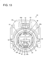
- the width of the female touching pieces 128a preferably is larger than that of the protection walls 130, the opposite left and right edges of the female contact portions 128a protrude from the protection walls 130 (see FIG. 13 ).
- the outer circumferential surfaces of these arcuate or bent protection walls 130 preferably have substantially the same radius of curvature as the outer circumferential surfaces of the likewise arcuate or bent female touching pieces 128a, and the outer circumferential surfaces of the protection walls 130 and those of the female touching pieces 128a at least partly overlap substantially in flush with each other when viewed from front.
- a distance from the outer circumferential surface of the terminal accommodating portion 121 to those of the protection walls 130 preferably is substantially equal to a distance from the outer circumferential surface of the terminal accommodating portion 121 to those of the female touching pieces 128a.
- each protection wall 130 is formed with at least one slit-like insertion hole 131 for permitting the penetration of the male touching piece 116a, the insertion hole 161 penetrating the protection wall 130 in forward and backward directions.
- a guiding slant 132 preferably is formed at the front opening edge of each insertion hole 131 (where the male touching piece 116a is inserted).
- the receptacle 114 Upon connecting the male housing 110 and the female housing 120, the receptacle 114 is lightly fitted into a cylindrical space between the terminal accommodating portion 121 and the tubular fitting portion 122, and one or more cam followers (not shown) having a known form and projecting from the outer circumferential surface of the male housing 110 are at least partly inserted into the entrances of cam grooves 134 of a movable member (such as a lever 133) mounted on the outer circumferential surface of the female housing 120. If the movable member is operated (preferably the lever 133 is rotated or pivoted) thereafter, the two housings 110, 120 are pulled toward each other to reach a connected state by cam action (or assisted by cam action) resulting from the engagement of the cam grooves 134 and the cam followers.
- a movable member such as a lever 133
- the leading end of the receptacle 114 might come into contact with the front end of the female shielding shell 128 (female touching pieces 128 and contact portions 128b) to cause an inadvertent deformation of the female shielding shell 128 such as buckling.
- the one or more protection walls 130 are provided substantially before the female shielding shell 128 in this embodiment, the receptacle 114 comes into contact only with the protection walls 130, but not with the front end of the female shielding shell 128 even if the leading end thereof heads toward the female shielding shell 128 from front.
- the protection walls 130 prevent the deformation of the female shielding shell 128 caused not only by the receptacle 114, but also by external matters that might at least partly enter the tubular fitting portion 122.
- the one or more insertion holes 131 are formed in the protection walls 130 and the one or more guiding slants 132 are formed at the opening edges of the insertion holes 131, there is no hindrance to an entering movement of the male shielding shell 116 into the clearance between the outer circumferential surface of the terminal accommodating portion 121 and the inner circumferential surface of the female shielding shell 128. Since the male shielding shell 116 having at least partly entered the insertion holes 131 has radial displacements thereof prevented, there is no likelihood that the leading end of the male shielding shell 116 comes into contact with the front end of the female shielding shell 128.
- the ribs 118 formed on the inner circumferential surface of the receptacle 114 slide on the outer circumferential surfaces of the protection walls 130, wherefore the shakes of the two housings 110, 120 in radial directions can be prevented.
- the ribs 118 of the receptacle 114 and the outer circumferential surface of the front end of the female shielding shell 128 are in contact with each other in radial directions. Since the front end of the female shielding shell 128 (i.e. contact portions 128b) has radially outward displacements thereof prevented by the contact with the receptacle 114, sufficient contact pressures can be ensured between the contact portions 128b of the female shielding shell 128 and the male shielding shell 116 held in contact with the inner circumferential surfaces of the contact portions 128b.
- the sealing member 126 is provided on the terminal accommodating portion 121 behind the contact position of the female shielding shell 128 and the male shielding shell 116 and more radially outward than the outer circumferential surfaces of the protection walls 130, and the inner circumferential surface of the leading end of the receptacle 114 comes substantially into close contact with the outer circumferential surface of the sealing member 126.
- areas of the inner circumferential surface of the receptacle 114 in contact with the protection walls 130 i.e. areas at the back end of the receptacle 114) are located more radially inward than the close contact position of the receptacle 114 with the sealing member 126 (i.e. leading end of the receptacle 114).
- the one or more ribs 118 are formed in the contact area with the protection walls 130 on the inner circumferential surface of the receptacle 114, and the inner circumferential surface of the receptacle 114 is held in contact with the outer circumferential surface of the protection walls 130 via these ribs 118.
- FIGS. 817 and 18 Next, a third preferred embodiment of the present invention is described with reference to FIGS. 817 and 18 .
- each protection wall 130 of the second embodiment is formed with a pushing portion 135. Since the other construction is similar or the same as in the second embodiment, the structure, functions and effects of the similar or same construction are not described by identifying this construction by the same reference numerals.
- Each pushing portion 135 projects backward (preferably in an overhanging or undercut manner) from the outer circumferential end edge of the protection wall 130 over at least part of, preferably over the substantially entire width of the protection wall 130, thereby forming an arcuate or bent or curved rib concentric with the outer circumferential surface of the terminal accommodating portion 121.
- the outer circumferential surface of the front end portion of the female shielding shell 128 i.e. part formed with the contact portions 128b with the male shielding shell 116) comes into contact with the inner circumferential surfaces of the pushing portions 135 substantially in radial directions.
- the front end portion (contact portions 128b) of the female shielding shell 128 has radially outward escaping displacements thereof prevented by these pressing portions 135, a sufficient contact pressure can be ensured between the female shielding shell 128 and the male shielding shell 116 held in contact with the inner circumferential surface of the female shielding shell 128. Further, the ribs 118 of the receptacle 114 can come substantially into sliding contact with the outer circumferential surfaces of the pushing portions 135.
- a fourth embodiment of the present invention is described with reference to FIG. 19 .
- One or more pushing portions 136 of the fourth embodiment are extended more backward than the one or more pushing portions 135 of the third embodiment so that the outer circumferential surfaces thereof substantially become continuous and/or flush with that of the surrounding portion 125 on which the sealing member 126 is to be mounted. Since the other construction is similar or the same as in the third embodiment, the structure, functions and effects of the similar or same construction are not described by identifying this construction by the same reference numerals.
- a fifth embodiment of the present invention is described with reference to FIGS. 20 and 21 .
- Contact portions 128c of the fifth embodiment differ from the contact portions 128b of the female touching pieces 128a of the fourth embodiment in shape. Since the other construction is similar or the same as in the fourth embodiment, the structure, functions and effects of the similar or same construction are not described by identifying this construction by the same reference numerals.
- the contact portion 128c extending substantially forward from the inner circumferential surface of the pushing portion 136 while being inclined to come closer to the outer circumferential surface of the terminal accommodating portion 121 is formed at or near the front end of the female contact portion 128a.
- a (preferably substantially semispherical) supporting point portion 137 projects at a position on the inner circumferential surface of each pushing portion 136 slightly behind the rear end of the contact portion 128c.
- the outer circumferential surface of the corresponding female touching piece 128a is substantially in contact with this supporting point portion 137. Unless the female shielding shell 128 is in contact with the male shielding shell 116, the front ends of the contact portions 128c are resiliently held in contact with the outer circumferential surface of the terminal accommodating portion 121.
- areas of the female touching pieces 128 before the supporting point portions 137 are so resiliently deformed as to be inclined toward the outer circumferential surface of the terminal accommodating portion 121 with the contact positions thereof with the supporting point portions 137 substantially as supporting points. Since a distance from the positions of the supporting points of resilient deformations (supporting point portions 137) to the contact positions (contact portions 128c) with the male shielding shell 116 when the female touching pieces 128a are resiliently deformed is stable in this embodiment, the amounts of resilient deformation of the female touching pieces 128a, i.e. resilient contact pressures of the contact portions 128c against the male shielding shell 116 can be stabilized.
- FIG. 22 A sixth preferred embodiment of the present invention is described with reference to FIG. 22 .
- Supporting point portions 138 of the sixth embodiment differ from those of the fifth embodiment in their form. Since the other construction is similar or the same as in the fifth embodiment, the structure, functions and effects of the similar or same construction are not described by identifying this construction by the same reference numerals.
- the supporting point portions 137 are formed on the inner circumferential surfaces of the pushing portions 136 in the fifth embodiment
- the one or more supporting point portions 138 are formed on the female touching pieces 128a in the sixth embodiment.
- the supporting point portions 138 are (preferably substantially semispherical) projections arranged behind the rear ends of the contact portions 128c and projecting outward. Unless the female shielding shell 128 is in contact with the male shielding shell 116, the supporting point portions 138 are held in contact with the inner circumferential surfaces of the pushing portions 136 and the front ends of the contact portions 128c are resiliently held in contact with the outer circumferential surface of the terminal accommodating portion 121.
- a male shielding shell 116 provided in the receptacle 114 is inserted in a clearance between the outer circumferential surface of the terminal accommodating portion 121 and the inner circumferential surface of a female shielding shell 128 to be connected with the female shielding shell 128. Since the terminal accommodating portion 121 is provided with protection walls 130 located before the front end of the female shielding shell 28, there is no likelihood of deforming the female shielding shell 128 by the interference of the receptacle 114 or the like from front. Each protection walls 130 is formed with an insertion hole 131 for permitting the entrance of the male shielding shell 116.
Landscapes
- Details Of Connecting Devices For Male And Female Coupling (AREA)
Abstract
characterized in that
said male shielding shell (116) is at least partly inserted in a clearance between the outer circumferential surface of the terminal accommodating portion (121) and the inner circumferential surface of the female shielding shell (128) to be connected with the female shielding shell (128), wherein:
the terminal accommodating portion (121) is provided with at least one protection wall (130) located before the front end of the female shielding shell (128), and
the protection wall (120) is formed with at least one insertion hole (131) for permitting the at least partial entrance of the male shielding shell (116).
Description
- The present invention relates to a shielded connector.
- Japanese Unexamined Patent Publication No.
H11-265754 - Since the shielding shell provided in the male housing and the one provided in the female housing differ in shape in the above conventional shielded connector, two kinds of shielding shells need to be produced, leading to increased production cost.
- Furthermore, Japanese Unexamined Patent Publication No.
H08-88050 - As means for connecting of the shells in the shielded connector of this type, such a construction can be thought in which a clearance is defined between the outer circumferential surface of the terminal accommodating portion and the inner circumferential surface of the shielding shell and the mating shell is inserted into this clearance.
- However, since the leading end of the shielding shell is distanced from the outer circumferential surface of the terminal accommodating portion in this construction, the leading end of the receptacle might interfere with that of the shielding shell to inadvertently deform the shielding shell if the male and female housings are connected while the axial lines thereof are inclined.
-
US -A-5 823 824 discloses a sealed connector including an inner housing accommodating a terminal, an outer housing surrounding the inner housing and a metallic shield positioned between the inner housing and the outer housing. - The present invention was developed in view of the above situation and an object thereof is to improve operability.
- This object is solved according to the invention by the features of the independent claims. Preferred embodiments of the invention are subject of the dependent claims.
- According to the invention, there is provided a shielded connector, in which a (preferably substantially tubular) female shielding shell is so provided as to extend along the outer circumferential surface of a terminal accommodating portion of a female housing and, with a receptacle of a male housing at least partly fitted on or to the terminal accommodating portion, a male shielding shell provided in the receptacle is at least partly inserted in a clearance between the outer circumferential surface of the terminal accommodating portion and the inner circumferential surface of the female shielding shell to be connected with the female shielding shell, wherein:
- the terminal accommodating portion is provided with at least one protection wall located before the front end of the female shielding shell, and
- the protection wall is formed with at least one insertion hole for permitting the at least partial entrance of the male shielding shell.
- Since the protection wall is provided before the female shielding shell, there is no likelihood of deforming the female shielding shell by the interference of the receptacle or the like from front thus improving the operability.
- According to a preferred embodiment of the invention, the outer circumferential surface of the protection wall can be held substantially in sliding contact with the inner circumferential surface of the receptacle in the process of connecting the male and female housings.
- Since the inner circumferential surface of the receptacle slides on the outer circumferential surface of the protection wall in the process of connecting the two housings, the shakes of the two housings in radial directions can be prevented.
- Preferably, the inner circumferential surface of the receptacle and the outer circumferential surface of the female shielding shell are held in contact substantially in radial directions with the male and female housings connected.
- Since the female shielding shell has a radially outward displacement thereof prevented by the receptacle with the two housings connected, a sufficient contact pressure can be ensured between the female shielding shell and the male shielding shell held in contact with the inner circumferential surface of the female shielding shell.
- Further preferably, at least one sealing member is mounted or to be mountedon the terminal accommodating portion at a position behind a contact position of the female shielding shell and the male shielding shell and/or more radially outward than the outer circumferential surface of the protection wall, and
preferably at least one rib which can come substantially into sliding contact with the outer circumferential surface of the protection wall is formed at a position of the inner circumferential surface of the receptacle behind a close contact position with the sealing member. - Since the inner circumferential surface of the receptacle comes substantially into close contact with the sealing member arranged more radially outward than the outer circumferential surface of the protection wall, a contact area of the inner circumferential surface of the receptacle with the protection wall is located more radially inward than the close contact position with the sealing member. However, since the at least one rib preferably is formed on the contact area with the protection wall in the present invention, the inner circumferential surface of the receptacle can be held in contact with the outer circumferential surface of the protection wall via this rib. Further, there is no likelihood of causing deformations called sinks in the receptacle during the molding since the rib is formed instead of increasing the thickness of the receptacle in order to hold the inner circumferential surface of the receptacle in contact with the outer circumferential surface of the protection wall.
- Most preferably, a front end portion of the female shielding shell serves as a contact portion with the male shielding shell, and
the protection wall is formed with at least one pushing portion with which the outer circumferential surface of the front end portion of the female shielding shell can come into contact. - Since the contact portion of the female shielding shell is so displaced by the pushing portion as to escape radially outward, a sufficient contact pressure can be ensured between the female shielding shell and the male shielding shell held in contact with the inner circumferential surface of the female shielding shell.
- According to the invention, there is further provided a shielded connector according to the above invention or a preferred embodiment thereof, in which a tubular shielding shell is provided in each of a male housing and a female housing connectable with each other and touching portions at the leading ends of the shielding shells are connected with the male and female housings connected, whereby an electrically conducting path in the male and female housings is shielded by the shielding shells, wherein:
- the touching portion of the shielding shell of the male housing is formed by arranging at least one outer touching piece having a contact point at the inner side and at least one inner touching piece having a contact point at the outer side in circumferential direction, and
- the shielding shell of the female housing has the same shape as that of the male housing and the outer and inner touching pieces thereof are so positioned in circumferential direction as to come into contact with the inner and outer touching pieces of the shielding shell of the male housing substantially in radial directions or in a direction at an angle different from 0° or 180°, preferably substantially normal to the connecting direction of the two housings.
- Since the shielding shell of the male housing and the shielding shell of the female housing have the same shape, operability can be improved and particularly costs (such as production costs and/or handling costs) can be reduced.
- According to a preferred embodiment of the invention, two outer touching pieces and two inner touching pieces are alternately arranged at intervals of about 90°.
- Such a positional relationship can be established in which the two outer touching pieces of one shielding shell are engaged with the two inner touching pieces of the other shielding shell while pressing them in radial directions and the two outer touching pieces of the other shielding shell are engaged with the two inner touching pieces of the one shielding shell while pressing them in radial directions, and the pressing directions are shifted by about 90°. Thus, there is no likelihood that the touching portion of the male housing and that of the female housing are displaced in radial directions, wherefore a contact state of the touching portions of the shielding shells is stabilized.
- Further preferably, the touching portion of the shielding shell of the male housing projects forward from a surface of the male housing substantially facing the female housing and is at least partly surrounded by a receptacle formed on the male housing.
- Still further preferably, one or more ribs extending along the outer surfaces of the outer touching pieces forming the touching portions are formed on the inner circumferential surface of the receptacle.
- Since radially outward reaction forces acting on the outer touching piece(s) of the male housing projecting in the receptacle from the inner touching piece(s) of the female housing are supported by the ribs, sufficient contact pressures can be ensured for the touching pieces.
- Most preferably, the inner touching pieces are resiliently deformable in radial directions independently of the outer touching pieces, preferably by providing one or more slits therebetween.
- These and other objects, features and advantages of the present invention will become more apparent upon reading of the following detailed description of preferred embodiments and accompanying drawings. It should be understood that even though embodiments are separately described, single features thereof may be combined to additional embodiments.
-
FIG. 1 is a horizontal section showing a state where male and female housings are connected in a first embodiment, -
FIG. 2 is a horizontal section showing a state where the male and female housings are separated, -
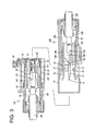
FIG. 3 is a vertical section showing the state where the male and female housings are separated, -
FIG. 4 is a section along X-X ofFIG. 1 , -
FIG. 5 is a front view of a shielding shell, -
FIG. 6 is a section along Y-Y ofFIG. 5 , -
FIG. 7 is a section along Z-Z ofFIG. 5 , -
FIG. 8 is a view from an direction of arrow A inFIG. 5 , and -
FIG. 9 is a side view of the male housing. -
FIG. 10 is a section showing a state where two male and female housings are separated in a second embodiment, -
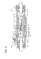
FIG. 11 is a section showing a state where the two housings are connected, -
FIG. 12 is a section of the female housing, -
FIG. 13 is a front view of the female housing, -
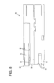
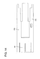
FIG. 14 is a side view of a female shielding shell, -
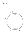
FIG. 15 is a front view of the female housing, -
FIG. 16 is a section along X-X ofFIG. 6 , -
FIG. 17 is a section showing a state where two male and female housings are connected in a third embodiment, -
FIG. 18 is a rear view of the female housing, -
FIG. 19 is a section of a female housing according to a fourth embodiment, -
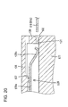
FIG. 20 is a partial enlarged section showing a state where a male shielding shell and a female shielding shell are not in contact in a fifth embodiment, -
FIG. 21 is a partial enlarged section showing a state where the male and female shielding shells are in contact, and -
FIG. 22 is a partial enlarged section of a sixth embodiment. - Hereinafter, a first preferred embodiment of the present invention is described with reference to
FIGS. 1 to 8 . A shielded connector of this embodiment is constructed such that amale housing 10M and afemale housing 10F are connected to connect the leading end of a shieldingshell 30 provided in themale housing 10M and that of a shieldingshell 30 provided at least partly in or on or at thefemale housing 10F, whereby an electrically conductingpath 41 at least partly accommodated in the male andfemale housings shells 30 for shielding. - The
male housing 10M is made e.g. of a synthetic resin and includes aninner housing 11M and anouter housing 12M at least partly surrounding the inner housing 11 M. The outer circumferential surface of theinner housing 11M (preferably substantially having a circular cross section) and the inner circumferential surface of theouter housing 12M (preferably substantially having a circular cross section) are connected by one or more, preferably four connectingportions 13M circumferentially spaced apart at substantially equal intervals (preferably in case of four connectingportions 13M of about 90°), and a (preferably substantially cylindrical)mount space 14M is formed in a clearance between the outer circumferential surface of theinner housing 11 M and the inner circumferential surface of theouter housing 12M. Further, the four connectingportions 13M preferably are arranged at 45°positions with respect to a vertical line and a transverse line, i.e. at right upper, left upper, right lower and left lower positions. - A
main portion 16M of a male terminal fitting 15M at least partly inserted from an insertion side, preferably substantially from behind, is retained by a lockingportion 17M in theinner housing 11 M, and acable 18M connected with the rear end of the male terminal fitting 15M passes through aback space 19M behind theinner housing 11M in theouter housing 12M to be drawn out of theouter housing 12M (male housing 10M). - An area of the
outer housing 12M before theinner housing 11 M serves as a (preferably substantially cylindrical)receptacle 20. A narrow andlong tab 21 formed at the front end of the male terminal fitting 15M projects from the front end surface of theinner housing 11 M to be at least partly accommodated into thereceptacle 20. One or more, preferably a plurality ofribs 22 extending substantially forward (direction parallel to a connecting direction CD of the twohousings inner housing 11M) or a position close thereto are formed on the inner circumferential surface of thereceptacle 20 while preferably being circumferentially spaced apart at substantially even intervals. A formation area of theribs 22 in forward and backward directions preferably is from the back end of the receptacle 20 (or close thereto) to a longitudinal intermediate position (preferably substantially a longitudinal middle position) thereof. - The shielding
shell 30 is to be mounted into themale housing 10M. The shieldingshell 30 is formed by applying bending, folding and/or embossing or the like to a conductive (preferably metal) plate material punched or cut out into a specified (predetermined or predeterminable) shape and preferably has a substantially tubular shape as a whole. A rear end portion of the shieldingshell 30 preferably is substantially cylindrical over the entire circumference, and a substantially 2/3 area of the shieldingshell 30 excluding the rear end portion is formed by one or more, preferably a pair of (preferably substantially vertically symmetrical)inner touching pieces 31 in the form of horizontal flat plates and one or more, preferably a pair of (preferably substantially bilaterally symmetrical) arcuate or bulged outer touchingpieces 32. The (preferably two)inner touching pieces 31 and the (preferably two) outer touchingpieces 32 are alternately arranged in circumferential direction at substantially even intervals (preferably at intervals of 90°). Specifically, even if the shieldingshell 30 of themale housing 10M is turned front side back about a vertical axial line or a transverse axial line, the twoinner touching pieces 31 are arranged at the upper and lower sides and the two outer touchingpieces 32 are arranged at the left and right sides. In other words, theinner touching pieces 31 and the outer touchingpieces 32 are substantially symmetrically arranged with respect to an axis of symmetry normal to the connecting direction CD (forward and backward directions) of the twohousings portions 13M. - A contact point with the shielding
shell 30 of thefemale housing 10F is provided at or near the leading end of the horizontal outer surface of each inner touchingpiece 31. On the other hand, each outer touchingpiece 32 is formed with aresilient touching piece 34 preferably by folding back a cantilever-shaped part extending from the front end edge backward and inward, and the inner surface of this resilient touchingpiece 34 serves as a contact point with the shieldingshell 30 of thefemale housing 10F. The front ends (leading ends) of the twoinner touching pieces 31 and those (leading ends) of the two outer touchingpieces 32 constitute or form part of a touchingportion 35 as contact means with the shieldingshell 30 of thefemale housing 10F. The adjacent inner and outer touchingpieces more slits 36 substantially extending straight backward from the front end of the shieldingshell 30. Since theslits 36 preferably are formed along the opposite lateral edges of theinner touching pieces 31, theinner touching pieces 31 are resiliently deformable in radial directions independently of the outer touchingpieces 32. - Such a shielding
shell 30 is at least partly inserted into theouter housing 12M (preferably substantially from behind) while theslits 36 are engaged with the connectingportions 13M, and areas of the inner and outer touchingpieces mount space 14M. The rear end portion of the shieldingshell 30 is so arranged as to substantially come into close contact with the inner circumferential surface of therear space 19M behind theinner housing 11 M in theouter housing 12M, and the front end portion (touching portion 35) thereof is located before theinner housing 11 M in thereceptacle 20. Here, since the outer touchingpieces 32 preferably have the outer circumferential surfaces thereof held in contact with theribs 22 substantially in radial directions, radially outward displacements thereof are prevented. - The
female housing 10F is made e.g. of a synthetic resin and includes aninner housing 11 F and anouter housing 12F at least partly surrounding the inner housing 11 F. The outer circumferential surface of theinner housing 11 F (preferably substantially having a circular cross section) and the inner circumferential surface of theouter housing 12F (preferably substantially having a circular cross section) are connected by one or more, preferably four connectingportions 13F preferably circumferentially spaced apart at substantially even intervals (in the case of four connectingportions 13F at intervals of about 90°), and a (preferably substantially cylindrical)mount space 14F is formed in a clearance between the outer circumferential surface of theinner housing 11 F and the inner circumferential surface of theouter housing 12F. Further, the four connectingportions 13F are arranged at about 45° positions with respect to a vertical line and a transverse line, i.e. at right upper, left upper, right lower and left lower positions. - A
main portion 16F of a male terminal fitting 15F (preferably inserted from behind) is retained by a lockingportion 17F in theinner housing 11 F, and acable 18F connected with the rear end of the male terminal fitting 15F passes through aback space 19F behind theinner housing 11 F in theouter housing 12F to be drawn out of theouter housing 12F (female housing 10F). Further, theouter housing 12F is formed with a (preferably substantially tubular) fitting portion 24 at least partly surrounding an area thereof corresponding to the inner housing F and having an open front side. Thereceptacle 20 of themale housing 10M is at least partly fittable or insertable into a clearance between this tubular fitting portion 24 and theouter housing 12F. - The shielding
shell 30 is mounted into thefemale housing 10F. The shieldingshell 30 preferably has the substantially same shape as the shieldingshell 30 of the abovemale housing 10M. Specifically, the two shieldingshells 30 preferably are the same kind of parts. With the shieldingshell 30 mounted in thefemale housing 10F, the almost entities of the inner and outer touchingpieces mount space 14F between theinner housing 11 F and theouter housing 12F. Further, radially outward displacements of the outer touchingpieces 32 preferably are prevented by the contact of the outer circumferential surfaces thereof with the inner circumferential surface of theouter housing 12F. - Whereas the two
inner touching pieces 31 are arranged e.g. at the upper and lower sides and the two outer touchingpieces 32 are arranged at the left and right sides in the shieldingshell 30 mounted in the abovemale housing 10M, the shieldingshell 30 of thisfemale housing 10F is mounted such that the twoinner touching pieces 31 are arranged at the left and right sides and the two outer touchingpieces 32 are arranged at the upper and lower sides. Specifically, this shieldingshell 30 in the substantially same orientation as the shieldingshell 30 of themale housing 10M is turned front side back with respect to a vertical axial line and the resulting shieldingshell 30 is rotated in circumferential direction by about 90° (or by an angle that is an integral multiple of the interval between the inner and outer touchingpieces 31, 32), the orientation of the shieldingshell 30 of thefemale housing 10F is set. - In other words, the inner and outer touching
pieces symmetry 33 of the shieldingshell 30 of thefemale housing 10F is substantially parallel to that 33 of the shieldingshell 30 of themale housing 10M. If the touchingportions 35 at the front ends are so opposed to each other that the both axes ofsymmetry 33 are substantially parallel in this way, theinner touching pieces 31 of one shieldingshell 30 substantially correspond to the outer touchingpieces 32 of the other shieldingshell 30, and the outer touchingpieces 32 of the oneshielding shell 30 substantially correspond to the outer touchingpieces 31 of the other shieldingshell 30. - Next, functions of this embodiment are described.
- The two
housings housings female housing 10F. Since connection means by the movable member (such as the lever 40) has a known construction, it is not described in detail. In the process of connecting the twohousings receptacle 20 at least partly enters the tubular fitting portion 24 and the front end portion of the shieldingshell 30 of themale housing 10M at least partly enters themount space 14F of thefemale housing 10F. With the twohousings tab 21 of the male terminal fitting 15M at least partly enters themain portion 16F of the female terminal fitting 15F, whereby the twoterminal fittings inner touching pieces 31 of themale housing 10M resiliently come into contact with the inner surfaces of the resilient touchingpieces 34 of the outer touchingpieces 32 of thefemale housing 10F, and the inner surfaces of the resilient touchingpieces 34 of the outer touchingpieces 32 of themale housing 10M resiliently come into contact with the outer surfaces of theinner touching pieces 31 of thefemale housing 10F, whereby the front ends (touching portions 35) of the both shieldingshells 30 are electrically connected. In this way, the electrically conductingpath 41 formed by the male terminal fitting 15M in themale housing 10M, the female terminal fitting 15F in thefemale housing 10F, an area of thecable 18M at least partly accommodated in themale housing 10M and an area of thecable 18F at least partly accommodated in thefemale housing 10F is shielded by being substantially surrounded by the shieldingshell 30 of themale housing 10M and the shieldingshell 30 of thefemale housing 10F. - In this embodiment, the shielding
shells 30 are formed such that the outer touchingpieces 32 having the contact points at the inner sides and theinner touching pieces 31 having the contact points at the outer sides are circumferentially arranged and the outer andinner touching pieces shell 30 of thefemale housing 10F respectively come into contact with the inner and outer touchingpieces shell 30 of themale housing 10M substantially in radial directions (or in a direction at an angle different from 0° or 180°, preferably substantially normal to the connecting direction CD). - The shielding
shells 30 preferably are also formed such that the outer andinner touching pieces symmetry 33 normal to the connecting direction CD of the twohousings shell 30 of thefemale housing 10F and the shieldingshell 30 of themale housing 10M are arranged such that the axes ofsymmetry 33 thereof are substantially parallel to each other. - Thus, the shielding
shell 30 of themale housing 10M and the shieldingshell 30 of thefemale housing 10F can preferably have the same shape, whereby a reduction in cost for parts could be realized. - Further, since the preferably two outer touching
pieces 32 and the preferably twoinner touching pieces 31 are alternately arranged preferably at intervals of about 90°, such a positional relationship can be established in which the two outer touchingpieces 32 of the oneshielding shell 30 are engaged with the twoinner touching pieces 31 of the other shieldingshell 30 while pressing them in radial direction (or in a direction at an angle different from 0° or 180°, preferably substantially normal to the connecting direction CD) and the two outer touchingpieces 32 of the other shieldingshell 30 are engaged with the twoinner touching pieces 31 of the oneshielding shell 30 while pressing them in radial directions (or in a direction at an angle different from 0° or 180°, preferably substantially normal to the connecting direction CD), and the pressing directions are circumferentially shifted preferably by about 90°. Thus, there is no likelihood that the touchingportion 35 of themale housing 10M and that of thefemale housing 10F are displaced in radial directions (vertical and transverse directions), wherefore a contact state of the touchingportions 35 of the shieldingshells 30 is stabilized. Further, contact reliability is high since the four contact positions are ensured by the touchingportions 35. - The touching
portion 35 of the shieldingshell 30 of themale housing 10M projects forward from a surface of themale housing 10M facing thefemale housing 10F (i.e. back end surface of the receptacle 20), and is surrounded by thereceptacle 20. Radially outward reaction forces acting on the outer touchingpieces 32 of themale housing 10M from theinner touching pieces 31 of thefemale housing 10F are supported by the one ormore ribs 22, wherefore sufficient contact pressures can be ensured for the touchingpieces - Accordingly, to reduce production costs, a shielding
shell 30 of amale housing 10M and a shieldingshell 30 of afemale housing 10F have the same shape, touchingportions 35 of the shieldingshells 30 are such that outer touchingpieces 32 having contact points at the inner sides andinner touching pieces 31 having contact points at the outer sides are arranged in circumferential direction, and theinner touching pieces 31 of one shieldingshell 30 and the outer touchingpieces 32 of the other shieldingshell 30 correspond to and come into contacting with each other in radial directions. Since the shieldingshell 30 of themale housing 10M and that of thefemale housing 10F have the same shape, cost can be reduced. - The present invention is not limited to the above described and illustrated embodiment. For example, the following embodiments are also embraced by the technical scope of the present invention as defined by the claims.
- (1) Although two each of the outer touching pieces and the inner touching pieces are provided in the foregoing embodiment, one each, three or more each of the outer and inner touching pieces may be provided according to the present invention.
- (2) Although only the outer touching pieces are provided with the resilient touching pieces in the foregoing embodiment, the resilient touching pieces may be provided only on the inner touching pieces or both on the outer and inner touching pieces according to the present invention.
- (3) Although the outer touching pieces are arcuate in the foregoing embodiment, they may be plate-like according to the present invention.
- (4) Although the inner touching pieces are plate-like in the foregoing embodiment, they may be curved according to the present invention.
- Hereinafter, a second embodiment of the present invention is described with reference to
FIGS. 9 to 16 . A shielded connector of this embodiment is comprised of amale housing 110 and afemale housing 120 connectable with and separable from each other along a connecting direction CD. - The
male housing 110 is made e.g. of a synthetic resin, wherein a terminalmain portion 112a of a male terminal fitting 112 (as a preferred electrically conducting path) is to be at least partly accommodated in a (preferably substantially cylindrical) housingmain body 111 whose axial line extends substantially in forward and backward directions (directions parallel to the connecting direction CD of the twohousings 110, 120) and a shieldedcable 113 connected with the rear end of the male terminal fitting 112 is drawn out preferably substantially backward from the housingmain body 111. The housingmain body 111 is formed with a (preferably substantially cylindrical) receptacle 114 projecting substantially forward, and atab 112b at the front end of the male terminal fitting 112 is at least partly accommodated in thereceptacle 114. One or more, preferably a plurality of mount holes 115 penetrating substantially in forward and backward directions are formed in the housingmain body 111 while preferably being circumferentially spaced apart, and a (preferably substantially cylindrical) metallicmale shielding shell 116 is mounted in these mount holes 115. A ahielding layer (preferably comprising abraided wire 113a) of the shieldedcable 113 is electrically to be connected with the rear end of themale shielding shell 116 via atubular connecting member 117. - The
male shielding shell 116 is formed with one or more, preferably a pair of (upper and lower) (preferably substantially cantilever-shaped)male touching pieces 116a extending substantially forward. Eachmale touching piece 116a preferably has a narrow and long shape with a substantially constant width, and the extending direction thereof is substantially parallel to connecting and separating directions of the twohousings male touching piece 116a serves as a touching portion with afemale shielding shell 128 and at least partly projects into thereceptacle 114 from the front end of the housingmain body 111. - Further, one or more, preferably a plurality of ribs extending substantially straight in forward and backward directions are formed on the inner circumferential surface of the
receptacle 114. A formation area of theribs 118 in forward and backward directions preferably is located only in a rear portion (preferably in a substantially rear half area) of thereceptacle 114, and neither theribs 118 nor other protuberances preferably are formed in a front portion (preferably in a substantially front half area) of thereceptacle 114. - The
female housing 120 is an integral assembly of a terminal accommodating portion made e.g. of a synthetic resin and preferably having a substantially cylindrical shape whose axial line extends in forward and backward directions and a substantially cylindrical tubularfitting portion 122 at least partly surrounding a front portion (preferably a substantially front half area) of theterminal accommodating portion 121. The tubularfitting portion 122 projects forward with the rear end thereof to be connected with the outer circumferential surface of theterminal accommodating portion 121. A female terminal fitting 123 (as a preferred electrically conducting path) is to be at least partly accommodated in theterminal accommodating portion 121, and a shieldedcable 124 connected with the rear end of the female terminal fitting 123 is drawn out preferably substantially backward from theterminal accommodating portion 121. - A
tubular surrounding portion 125 for surrounding at least a part of thefemale shielding shell 128 to be described later is formed at or near the back end of the tubularfitting portion 122, and a ring-shapedsealing member 126 is to be mounted on the outer circumferential surface of the surroundingportion 125. The sealingmember 126 is located more radially outward than the outer circumferential surface of thefemale shielding shell 128. - One or more, preferably a plurality of mount holes 127 penetrating substantially in forward and backward directions are formed in the
terminal accommodating portion 121 while preferably being circumferentially spaced apart. The substantially cylindrical metallicfemale shielding shell 128 is mounted in these mount holes 127. A shielding layer (preferably comprising a braided wire orshield film 124a) of the shieldedcable 124 is to be electrically connected with the rear end of thefemale shielding shell 128 preferably via atubular connecting member 129. - The
female shielding shell 128 is formed with one or more, preferably a pair of (upper and lower) (preferably substantially cantilever-shaped)female touching pieces 128a in the form of plates preferably curved to have an arcuate shape substantially concentric with theterminal accommodating portion 121 and extending forward along the outer circumferential surface of theterminal accommodating portion 121. Thefemale touching pieces 128a are spaced from the outer circumferential surface of theterminal accommodating portion 121 and the extending direction thereof is substantially parallel to the connecting and separating directions of the twohousings contact portion 128b extending backward by being folded back inwardly is formed at or near the front end of eachfemale touching piece 128a. Thecontact portion 128b preferably has a width narrower than that of thefemale touching piece 128a and is located in a widthwise intermediate position (preferably substantially in the widthwise center) of thefemale touching piece 128a. The width of thecontact portion 128b preferably is substantially equal to that of themale touching piece 116a. Although the inner surfaces of thecontact portions 128b are resiliently in contact with the outer circumferential surface of theterminal accommodating portion 121 with the twohousings male touching pieces 116a are at least partly inserted into clearances between thecontact portions 128b and theterminal accommodating portion 121 and the outer surfaces of themale touching pieces 116a and the inner surfaces of thecontact portions 128b are electrically and resiliently in contact with the twohousings - One or more, preferably a pair of (upper and lower)
protection walls 130 are integrally or unitarily formed at or near the front end of the outer circumferential surface of theterminal accommodating portion 121. Theprotection walls 130 preferably are substantially fan-shaped by extending in circumferential direction along the outer circumference of the front end of theterminal accommodating portion 21 while preferably being substantially concentric with theterminal accommodating portion 121 and are located more forward than the front ends (contactportions 128b) of thefemale touching pieces 128a, and the front surfaces of theprotection walls 130 substantially are continuous and/or flush with the front surface of theterminal accommodating portion 121. A formation area of theprotection walls 130 in circumferential direction preferably is wider than a formation area of thecontact portions 128b so as to cover thecontact portions 128b from front over at least part of, preferably the substantially entire widths. However, since the width of thefemale touching pieces 128a preferably is larger than that of theprotection walls 130, the opposite left and right edges of thefemale contact portions 128a protrude from the protection walls 130 (seeFIG. 13 ). - The outer circumferential surfaces of these arcuate or
bent protection walls 130 preferably have substantially the same radius of curvature as the outer circumferential surfaces of the likewise arcuate or bentfemale touching pieces 128a, and the outer circumferential surfaces of theprotection walls 130 and those of thefemale touching pieces 128a at least partly overlap substantially in flush with each other when viewed from front. Specifically, a distance from the outer circumferential surface of theterminal accommodating portion 121 to those of theprotection walls 130 preferably is substantially equal to a distance from the outer circumferential surface of theterminal accommodating portion 121 to those of thefemale touching pieces 128a. Further, eachprotection wall 130 is formed with at least one slit-like insertion hole 131 for permitting the penetration of themale touching piece 116a, the insertion hole 161 penetrating theprotection wall 130 in forward and backward directions. Further, a guidingslant 132 preferably is formed at the front opening edge of each insertion hole 131 (where themale touching piece 116a is inserted). - Next, functions of the second embodiment are described.
- Upon connecting the
male housing 110 and thefemale housing 120, thereceptacle 114 is lightly fitted into a cylindrical space between the terminalaccommodating portion 121 and the tubularfitting portion 122, and one or more cam followers (not shown) having a known form and projecting from the outer circumferential surface of themale housing 110 are at least partly inserted into the entrances ofcam grooves 134 of a movable member (such as a lever 133) mounted on the outer circumferential surface of thefemale housing 120. If the movable member is operated (preferably thelever 133 is rotated or pivoted) thereafter, the twohousings cam grooves 134 and the cam followers. - In the process of connecting the two
housings receptacle 114 entering the tubularfitting portion 122 is oblique, the leading end of thereceptacle 114 might come into contact with the front end of the female shielding shell 128 (female touchingpieces 128 andcontact portions 128b) to cause an inadvertent deformation of thefemale shielding shell 128 such as buckling. However, since the one ormore protection walls 130 are provided substantially before thefemale shielding shell 128 in this embodiment, thereceptacle 114 comes into contact only with theprotection walls 130, but not with the front end of thefemale shielding shell 128 even if the leading end thereof heads toward thefemale shielding shell 128 from front. Theprotection walls 130 prevent the deformation of thefemale shielding shell 128 caused not only by thereceptacle 114, but also by external matters that might at least partly enter the tubularfitting portion 122. - Further, since the one or
more insertion holes 131 are formed in theprotection walls 130 and the one or more guiding slants 132 are formed at the opening edges of the insertion holes 131, there is no hindrance to an entering movement of themale shielding shell 116 into the clearance between the outer circumferential surface of theterminal accommodating portion 121 and the inner circumferential surface of thefemale shielding shell 128. Since themale shielding shell 116 having at least partly entered the insertion holes 131 has radial displacements thereof prevented, there is no likelihood that the leading end of themale shielding shell 116 comes into contact with the front end of thefemale shielding shell 128. - In the process of connecting the two
housings ribs 118 formed on the inner circumferential surface of thereceptacle 114 slide on the outer circumferential surfaces of theprotection walls 130, wherefore the shakes of the twohousings - Further, with the
male housing 110 and thefemale housing 120 connected, theribs 118 of thereceptacle 114 and the outer circumferential surface of the front end of thefemale shielding shell 128 are in contact with each other in radial directions. Since the front end of the female shielding shell 128 (i.e.contact portions 128b) has radially outward displacements thereof prevented by the contact with thereceptacle 114, sufficient contact pressures can be ensured between thecontact portions 128b of thefemale shielding shell 128 and themale shielding shell 116 held in contact with the inner circumferential surfaces of thecontact portions 128b. - In this embodiment, the sealing
member 126 is provided on theterminal accommodating portion 121 behind the contact position of thefemale shielding shell 128 and themale shielding shell 116 and more radially outward than the outer circumferential surfaces of theprotection walls 130, and the inner circumferential surface of the leading end of thereceptacle 114 comes substantially into close contact with the outer circumferential surface of the sealingmember 126. Thus, areas of the inner circumferential surface of thereceptacle 114 in contact with the protection walls 130 (i.e. areas at the back end of the receptacle 114) are located more radially inward than the close contact position of thereceptacle 114 with the sealing member 126 (i.e. leading end of the receptacle 114). Accordingly, the one ormore ribs 118 are formed in the contact area with theprotection walls 130 on the inner circumferential surface of thereceptacle 114, and the inner circumferential surface of thereceptacle 114 is held in contact with the outer circumferential surface of theprotection walls 130 via theseribs 118. - It may be thought to increase the thickness of the
receptacle 114 in order to hold the inner circumferential surface of thereceptacle 114 in contact with the outer circumferential surfaces of theprotection walls 130, but thereceptacle 114 might be deformed due to sinks in the process of molding themale housing 110 in this case. In this respect, in this embodiment, a method for forming theribs 118 is adopted instead of thickening. Thus, there is no likelihood of causing deformations of thereceptacle 114 called sinks during the molding. - Next, a third preferred embodiment of the present invention is described with reference to FIGS. 817 and
18 . - In the third embodiment, each
protection wall 130 of the second embodiment is formed with a pushingportion 135. Since the other construction is similar or the same as in the second embodiment, the structure, functions and effects of the similar or same construction are not described by identifying this construction by the same reference numerals. - Each pushing
portion 135 projects backward (preferably in an overhanging or undercut manner) from the outer circumferential end edge of theprotection wall 130 over at least part of, preferably over the substantially entire width of theprotection wall 130, thereby forming an arcuate or bent or curved rib concentric with the outer circumferential surface of theterminal accommodating portion 121. The outer circumferential surface of the front end portion of the female shielding shell 128 (i.e. part formed with thecontact portions 128b with the male shielding shell 116) comes into contact with the inner circumferential surfaces of the pushingportions 135 substantially in radial directions. Since the front end portion (contact portions 128b) of thefemale shielding shell 128 has radially outward escaping displacements thereof prevented by thesepressing portions 135, a sufficient contact pressure can be ensured between thefemale shielding shell 128 and themale shielding shell 116 held in contact with the inner circumferential surface of thefemale shielding shell 128. Further, theribs 118 of thereceptacle 114 can come substantially into sliding contact with the outer circumferential surfaces of the pushingportions 135. - A fourth embodiment of the present invention is described with reference to
FIG. 19 . One or more pushingportions 136 of the fourth embodiment are extended more backward than the one or more pushingportions 135 of the third embodiment so that the outer circumferential surfaces thereof substantially become continuous and/or flush with that of the surroundingportion 125 on which the sealingmember 126 is to be mounted. Since the other construction is similar or the same as in the third embodiment, the structure, functions and effects of the similar or same construction are not described by identifying this construction by the same reference numerals. - Since areas of the
female touching pieces 128a of thefemale shielding shell 128 corresponding to theterminal accommodating portion 121 in forward and backward directions are covered over at least part of, preferably over the substantially entire length according to the fourth embodiment, the interference of thereceptacle 114 and thefemale touching pieces 128a can be reliably prevented. - A fifth embodiment of the present invention is described with reference to
FIGS. 20 and21 . Contactportions 128c of the fifth embodiment differ from thecontact portions 128b of thefemale touching pieces 128a of the fourth embodiment in shape. Since the other construction is similar or the same as in the fourth embodiment, the structure, functions and effects of the similar or same construction are not described by identifying this construction by the same reference numerals. - The
contact portion 128c extending substantially forward from the inner circumferential surface of the pushingportion 136 while being inclined to come closer to the outer circumferential surface of theterminal accommodating portion 121 is formed at or near the front end of thefemale contact portion 128a. Further, a (preferably substantially semispherical) supportingpoint portion 137 projects at a position on the inner circumferential surface of each pushingportion 136 slightly behind the rear end of thecontact portion 128c. The outer circumferential surface of the correspondingfemale touching piece 128a is substantially in contact with this supportingpoint portion 137. Unless thefemale shielding shell 128 is in contact with themale shielding shell 116, the front ends of thecontact portions 128c are resiliently held in contact with the outer circumferential surface of theterminal accommodating portion 121. - If the
male shielding shell 116 is at least partly inserted into the clearance between thefemale shielding shell 128 and theterminal accommodating portion 121 by passing theprotection walls 130, areas of the female touchingpieces 128 before the supporting point portions 137 (i.e. areas including thecontact portions 128c) are so resiliently deformed as to be inclined toward the outer circumferential surface of theterminal accommodating portion 121 with the contact positions thereof with the supportingpoint portions 137 substantially as supporting points. Since a distance from the positions of the supporting points of resilient deformations (supporting point portions 137) to the contact positions (contactportions 128c) with themale shielding shell 116 when thefemale touching pieces 128a are resiliently deformed is stable in this embodiment, the amounts of resilient deformation of thefemale touching pieces 128a, i.e. resilient contact pressures of thecontact portions 128c against themale shielding shell 116 can be stabilized. - A sixth preferred embodiment of the present invention is described with reference to
FIG. 22 . Supportingpoint portions 138 of the sixth embodiment differ from those of the fifth embodiment in their form. Since the other construction is similar or the same as in the fifth embodiment, the structure, functions and effects of the similar or same construction are not described by identifying this construction by the same reference numerals. - Although the supporting
point portions 137 are formed on the inner circumferential surfaces of the pushingportions 136 in the fifth embodiment, the one or moresupporting point portions 138 are formed on thefemale touching pieces 128a in the sixth embodiment. The supportingpoint portions 138 are (preferably substantially semispherical) projections arranged behind the rear ends of thecontact portions 128c and projecting outward. Unless thefemale shielding shell 128 is in contact with themale shielding shell 116, the supportingpoint portions 138 are held in contact with the inner circumferential surfaces of the pushingportions 136 and the front ends of thecontact portions 128c are resiliently held in contact with the outer circumferential surface of theterminal accommodating portion 121. - Accordingly, to prevent the deformation of a shielding shell, with a
receptacle 114 of amale housing 110 fitted on aterminal accommodating portion 121, amale shielding shell 116 provided in thereceptacle 114 is inserted in a clearance between the outer circumferential surface of theterminal accommodating portion 121 and the inner circumferential surface of afemale shielding shell 128 to be connected with thefemale shielding shell 128. Since theterminal accommodating portion 121 is provided withprotection walls 130 located before the front end of the female shielding shell 28, there is no likelihood of deforming thefemale shielding shell 128 by the interference of thereceptacle 114 or the like from front. Eachprotection walls 130 is formed with aninsertion hole 131 for permitting the entrance of themale shielding shell 116. - The present invention is not limited to the above described and illustrated embodiments. For example, the following embodiments are also embraced by the technical scope of the present invention as defined by the claims.
- (1) The protection walls may be formed such that the front surfaces thereof are located more backward than the front end surface of the terminal accommodating portion.
- (2) The protection walls may be parts separate from the terminal accommodating portion.
- (3) In the connecting process of the two housings, the outer circumferential surfaces of the protection walls and the inner circumferential surface of the receptacle may not be in contact.
- (4) With the two housings connected, the inner circumferential surface of the receptacle and the outer circumferential surface of the female shielding shell may not be in contact.
- (5) In order to hold the inner circumferential surface of the receptacle into contact with the protection walls, the thickness of the receptacle may be increased for the contact with the protection walls instead of forming the ribs.
-
- 10M ... male housing
- 10F ... female housing
- 15M ... male terminal fitting (electrically conducting path)
- 15F ... female terminal fitting (electrically conducting path)
- 20 ... receptacle
- 22 ... rib
- 30 ... shielding shell
- 31 ... inner touching piece
- 32 ... outer touching piece
- 33 ... axis of symmetry
- 35 ... touching portion
- 41 ... electrically conducting path
- 110 ... male housing
- 112 ... male terminal fitting (electrically conducting path)
- 114 ... receptacle
- 116 ... male shielding shell
- 118 ... rib
- 120 ... female housing
- 123 ... female terminal fitting (electrically conducting path)
- 121 ... terminal accommodating portion
- 126 ... sealing member
- 128 ... female shielding shell
- 130 ... protection wall
- 131 ... insertion hole
- 135 ... pushing portion
Claims (10)
- A shielded connector, in which a female shielding shell (128) is so provided as to extend along the outer circumferential surface of a terminal accommodating portion (121) of a female housing (120) and, with a receptacle (114) of a male housing (110) at least partly fitted on the terminal accommodating portion (121), a male shielding shell (116) provided in the receptacle (114) is connected with the female shielding shell (128),
characterized in that
said male shielding shell (116) is at least partly inserted in a clearance between the outer circumferential surface of the terminal accommodating portion (121) and the inner circumferential surface of the female shielding shell (128) to be connected with the female shielding shell (128), wherein:the terminal accommodating portion (121) is provided with at least one protection wall (130) located before the front end of the female shielding shell (128), andthe protection wall (130) is formed with at least one insertion hole (131) for permitting the at least partial entrance of the male shielding shell (116). - A shielded connector according to claim 1, wherein the outer circumferential surface of the protection wall (130) can be held substantially in sliding contact with the inner circumferential surface of the receptacle (114) in the process of connecting the male and female housings (110, 120).
- A shielded connector according to one or more of the preceding claims, wherein the inner circumferential surface of the receptacle (114) and the outer circumferential surface of the female shielding shell (128) are held in contact substantially in radial directions with the male and female housings connected (110, 120).
- A shielded connector according to claim 2 or 3, wherein:at least one sealing member (126) is mounted on the terminal accommodating portion (121) at a position behind a contact position of the female shielding shell (128) and the male shielding shell (116) and/or more radially outward than the outer circumferential surface of the protection wall (130), andpreferably at least one rib (118) which can come substantially into sliding contact with the outer circumferential surface of the protection wall (130) is formed at a position of the inner circumferential surface of the receptacle (114) behind a close contact position with the sealing member (126).
- A shielded connector according to any one of the preceding claims, in which a tubular shielding shell (30) is provided in each of a male housing (10M) and a female housing (10F) connectable with each other and touching portions (35) at or near the leading ends of the shielding shells (30) are connected with the male and female housings (10M, 10F) connected, whereby an electrically conducting path (15M, 15F) in the male and female housings (10M, 10F) is shielded by the shielding shells (30), wherein:the touching portion (35) of the shielding shell (30) of the male housing (10M) is formed by arranging at least one outer touching piece (32) having a contact point at the inner side and at least one inner touching piece (31) having a contact point at the outer side in circumferential direction, andthe shielding shell (30) of the female housing (10F) has the same shape as that of the male housing (10M) and the outer and inner touching pieces (32, 31) thereof are so positioned in circumferential direction as to come into contact with the inner and outer touching pieces (31, 32) of the shielding shell (30) of the male housing (10M) substantially in radial directions.
- A shielded connector according to claim 5, wherein two outer touching pieces (32) and two inner touching pieces (31) are alternately arranged at intervals of about 90°.
- A shielded connector according to one or more of the preceding claims, wherein the touching portion (35) of the shielding shell (30) of the male housing (10M) projects forward from a surface of the male housing (10M) substantially facing the female housing (10F) and is at least partly surrounded by a receptacle (20) formed on the male housing (10M).
- A shielded connector according to claim 7, wherein one or more ribs (22) extending along the outer surfaces of the outer touching pieces (32) forming the touching portions (35) are formed on the inner circumferential surface of the receptacle (20).
- A shielded connector according to one or more of the preceding claims, wherein the inner touching pieces (31) are resiliently deformable in radial directions independently of the outer touching pieces (32), preferably by providing one or more slits (36) therebetween.
- A shielded connector according to one or more of the preceding claims, wherein:a front end portion of the female shielding shell (128) serves as a contact portion with the male shielding shell (116), andthe protection wall (130) is formed with at least one pushing portion (135) with which the outer circumferential surface of the front end portion of the female shielding shell (128) can come into contact.
Applications Claiming Priority (3)
| Application Number | Priority Date | Filing Date | Title |
|---|---|---|---|
| JP2006312724A JP4821573B2 (en) | 2006-11-20 | 2006-11-20 | Shield connector |
| JP2007042235A JP4779993B2 (en) | 2007-02-22 | 2007-02-22 | Shield connector |
| EP07021941A EP1923961B1 (en) | 2006-11-20 | 2007-11-12 | A shielded connector and shielding shell |
Related Parent Applications (1)
| Application Number | Title | Priority Date | Filing Date |
|---|---|---|---|
| EP07021941.5 Division | 2007-11-12 |
Publications (2)
| Publication Number | Publication Date |
|---|---|
| EP2296234A1 true EP2296234A1 (en) | 2011-03-16 |
| EP2296234B1 EP2296234B1 (en) | 2012-01-04 |
Family
ID=39027222
Family Applications (2)
| Application Number | Title | Priority Date | Filing Date |
|---|---|---|---|
| EP07021941A Expired - Fee Related EP1923961B1 (en) | 2006-11-20 | 2007-11-12 | A shielded connector and shielding shell |
| EP10014996A Not-in-force EP2296234B1 (en) | 2006-11-20 | 2007-11-12 | A shielded connector |
Family Applications Before (1)
| Application Number | Title | Priority Date | Filing Date |
|---|---|---|---|
| EP07021941A Expired - Fee Related EP1923961B1 (en) | 2006-11-20 | 2007-11-12 | A shielded connector and shielding shell |
Country Status (4)
| Country | Link |
|---|---|
| US (1) | US7485002B2 (en) |
| EP (2) | EP1923961B1 (en) |
| KR (1) | KR100937464B1 (en) |
| AT (1) | ATE540450T1 (en) |
Cited By (3)
| Publication number | Priority date | Publication date | Assignee | Title |
|---|---|---|---|---|
| EP4315523A4 (en) * | 2021-04-01 | 2025-02-19 | J.S.T. Corporation | A method for electromagnetic interference (emi) protection for a high voltage connector assembly having a conductive outer housing, with at least a conductive tab, that accommodates therein a seal spring |
| EP4315520A4 (en) * | 2021-04-01 | 2025-02-26 | J.S.T. Corporation | Elastomer seal spring |
| EP4315524A4 (en) * | 2021-04-01 | 2025-02-26 | J.S.T. Corporation | An outer housing, having at least a conductive tab, for accommodating therein a seal spring |
Families Citing this family (13)
| Publication number | Priority date | Publication date | Assignee | Title |
|---|---|---|---|---|
| JP5186170B2 (en) * | 2007-10-05 | 2013-04-17 | 矢崎総業株式会社 | Conductive member and connector having the conductive member |
| GB2469487B (en) | 2009-04-15 | 2012-08-15 | Tyco Electronics Ltd Uk | Coaxial cable connector and associated method |
| JP5339154B2 (en) * | 2010-01-14 | 2013-11-13 | 住友電装株式会社 | Shield connector |
| JP5585608B2 (en) * | 2012-04-23 | 2014-09-10 | 第一精工株式会社 | Coaxial electrical connector |
| DE102012110232B4 (en) * | 2012-10-26 | 2023-11-23 | Dr. Ing. H.C. F. Porsche Aktiengesellschaft | Connection device for power transmission in the motor vehicle sector |
| WO2015164538A1 (en) | 2014-04-23 | 2015-10-29 | Tyco Electronics Corporation | Electrical connector with shield cap and shielded terminals |
| KR20160081060A (en) | 2014-12-30 | 2016-07-08 | 한국단자공업 주식회사 | Terminal and connector using the terminal |
| US11527846B2 (en) | 2016-02-12 | 2022-12-13 | Commscope Technologies Llc | Ganged coaxial connector assembly |
| US10950970B2 (en) | 2018-04-04 | 2021-03-16 | Commscope Technologies Llc | Ganged coaxial connector assembly |
| US11309650B2 (en) * | 2017-08-01 | 2022-04-19 | Aptiv Technologies Limited | Sealed connector assembly |
| WO2019195504A1 (en) | 2018-04-04 | 2019-10-10 | Commscope Technologies Llc | Ganged coaxial connector assembly |
| DE102019200713B3 (en) * | 2019-01-22 | 2020-07-23 | Robert Bosch Gmbh | Ethernet connector for a motor vehicle and connector assembly with an Ethernet connector |
| JP7149542B2 (en) * | 2020-05-27 | 2022-10-07 | 矢崎総業株式会社 | connector |
Citations (4)
| Publication number | Priority date | Publication date | Assignee | Title |
|---|---|---|---|---|
| JPH0888050A (en) | 1994-09-16 | 1996-04-02 | Sumitomo Wiring Syst Ltd | Shielded connector |
| US5803767A (en) * | 1995-03-23 | 1998-09-08 | Yazaki Corporation | Insulating structure for a coaxial connector |
| US5823824A (en) | 1994-03-07 | 1998-10-20 | Yazaki Corporation | Sealed connector |
| JPH11265754A (en) | 1999-02-08 | 1999-09-28 | Sumitomo Wiring Syst Ltd | Waterproof shield connector |
Family Cites Families (2)
| Publication number | Priority date | Publication date | Assignee | Title |
|---|---|---|---|---|
| US5857867A (en) * | 1997-07-17 | 1999-01-12 | The Whitaker Corporation | Hermaphroditic coaxial connector |
| DE19848835A1 (en) * | 1998-10-22 | 2000-04-27 | W W Fischer Sa Apples | Multiple pole plug connector has contact spring arrangement formed on longitudinal edge(s) of cylindrical shell(s) that makes contact with edge of adjacent shell in correctly assembled state |
-
2007
- 2007-11-12 EP EP07021941A patent/EP1923961B1/en not_active Expired - Fee Related
- 2007-11-12 AT AT10014996T patent/ATE540450T1/en active
- 2007-11-12 EP EP10014996A patent/EP2296234B1/en not_active Not-in-force
- 2007-11-15 US US11/940,529 patent/US7485002B2/en not_active Expired - Fee Related
- 2007-11-20 KR KR1020070118850A patent/KR100937464B1/en not_active Expired - Fee Related
Patent Citations (4)
| Publication number | Priority date | Publication date | Assignee | Title |
|---|---|---|---|---|
| US5823824A (en) | 1994-03-07 | 1998-10-20 | Yazaki Corporation | Sealed connector |
| JPH0888050A (en) | 1994-09-16 | 1996-04-02 | Sumitomo Wiring Syst Ltd | Shielded connector |
| US5803767A (en) * | 1995-03-23 | 1998-09-08 | Yazaki Corporation | Insulating structure for a coaxial connector |
| JPH11265754A (en) | 1999-02-08 | 1999-09-28 | Sumitomo Wiring Syst Ltd | Waterproof shield connector |
Cited By (3)
| Publication number | Priority date | Publication date | Assignee | Title |
|---|---|---|---|---|
| EP4315523A4 (en) * | 2021-04-01 | 2025-02-19 | J.S.T. Corporation | A method for electromagnetic interference (emi) protection for a high voltage connector assembly having a conductive outer housing, with at least a conductive tab, that accommodates therein a seal spring |
| EP4315520A4 (en) * | 2021-04-01 | 2025-02-26 | J.S.T. Corporation | Elastomer seal spring |
| EP4315524A4 (en) * | 2021-04-01 | 2025-02-26 | J.S.T. Corporation | An outer housing, having at least a conductive tab, for accommodating therein a seal spring |
Also Published As
| Publication number | Publication date |
|---|---|
| US20080119087A1 (en) | 2008-05-22 |
| EP1923961A2 (en) | 2008-05-21 |
| ATE540450T1 (en) | 2012-01-15 |
| EP1923961A3 (en) | 2010-08-04 |
| KR20080045658A (en) | 2008-05-23 |
| EP2296234B1 (en) | 2012-01-04 |
| KR100937464B1 (en) | 2010-01-19 |
| US7485002B2 (en) | 2009-02-03 |
| EP1923961B1 (en) | 2011-08-31 |
Similar Documents
| Publication | Publication Date | Title |
|---|---|---|
| EP2296234B1 (en) | A shielded connector | |
| US7238050B2 (en) | Shielded connector | |
| US7731536B2 (en) | Shielded connector | |
| US7938695B2 (en) | Terminal fitting | |
| US10741976B1 (en) | Shield connector and male shield terminal | |
| CN111628321B (en) | Shielding terminal and shielding connector | |
| EP1863129B1 (en) | A ground terminal for shielded cables and method of assembling it | |
| EP2346120B1 (en) | Shield connector and production method thereof | |
| US7488211B2 (en) | Terminal fitting and a shield terminal | |
| CN107895868B (en) | Shielded connector | |
| US8317553B2 (en) | Terminal fitting with an entrance preventing wall | |
| EP1608045A2 (en) | A shielded connector and method of connecting it with a shielded conductor path | |
| US10707587B2 (en) | Connector and terminal fitting | |
| JP6243277B2 (en) | Shield connector | |
| EP2051335B1 (en) | A connector | |
| JP2010182647A (en) | Shield connector and shield shell | |
| EP1693932A1 (en) | A shielded connector, mating shielded connector and shielded connector assembly | |
| EP1689036A1 (en) | A terminal fitting, a connector provided therewith and a method of forming a terminal fitting | |
| US11322895B2 (en) | Connector shielding with a circumferential retention element | |
| US20110104921A1 (en) | Connector and series of connectors | |
| US11437738B2 (en) | Connector with a housing having a confirmation window | |
| KR102866341B1 (en) | electrical terminals | |
| US7789715B2 (en) | Terminal fitting with posture correcting edge and inclination restricting portion and a connector provided therewith | |
| US20240396247A1 (en) | Female connector | |
| JPH11502971A (en) | Shield assembly for electrical connector |
Legal Events
| Date | Code | Title | Description |
|---|---|---|---|
| PUAI | Public reference made under article 153(3) epc to a published international application that has entered the european phase |
Free format text: ORIGINAL CODE: 0009012 |
|
| AC | Divisional application: reference to earlier application |
Ref document number: 1923961 Country of ref document: EP Kind code of ref document: P |
|
| AK | Designated contracting states |
Kind code of ref document: A1 Designated state(s): AT BE BG CH CY CZ DE DK EE ES FI FR GB GR HU IE IS IT LI LT LU LV MC MT NL PL PT RO SE SI SK TR |
|
| AX | Request for extension of the european patent |
Extension state: AL BA HR MK RS |
|
| GRAP | Despatch of communication of intention to grant a patent |
Free format text: ORIGINAL CODE: EPIDOSNIGR1 |
|
| 17P | Request for examination filed |
Effective date: 20110609 |
|
| RIC1 | Information provided on ipc code assigned before grant |
Ipc: H01R 13/28 20060101AFI20110630BHEP |
|
| GRAC | Information related to communication of intention to grant a patent modified |
Free format text: ORIGINAL CODE: EPIDOSCIGR1 |
|
| RIN1 | Information on inventor provided before grant (corrected) |
Inventor name: NODA, MASAHIRO Inventor name: NISHIDE, SATORU |
|
| RAP1 | Party data changed (applicant data changed or rights of an application transferred) |
Owner name: SUMITOMO WIRING SYSTEMS, LTD. |
|
| GRAS | Grant fee paid |
Free format text: ORIGINAL CODE: EPIDOSNIGR3 |
|
| GRAA | (expected) grant |
Free format text: ORIGINAL CODE: 0009210 |
|
| AC | Divisional application: reference to earlier application |
Ref document number: 1923961 Country of ref document: EP Kind code of ref document: P |
|
| AK | Designated contracting states |
Kind code of ref document: B1 Designated state(s): AT BE BG CH CY CZ DE DK EE ES FI FR GB GR HU IE IS IT LI LT LU LV MC MT NL PL PT RO SE SI SK TR |
|
| REG | Reference to a national code |
Ref country code: GB Ref legal event code: FG4D |
|
| REG | Reference to a national code |
Ref country code: CH Ref legal event code: EP |
|
| REG | Reference to a national code |
Ref country code: AT Ref legal event code: REF Ref document number: 540450 Country of ref document: AT Kind code of ref document: T Effective date: 20120115 |
|
| REG | Reference to a national code |
Ref country code: IE Ref legal event code: FG4D |
|
| REG | Reference to a national code |
Ref country code: DE Ref legal event code: R096 Ref document number: 602007019896 Country of ref document: DE Effective date: 20120308 |
|
| REG | Reference to a national code |
Ref country code: NL Ref legal event code: VDEP Effective date: 20120104 |
|
| PG25 | Lapsed in a contracting state [announced via postgrant information from national office to epo] |
Ref country code: SI Free format text: LAPSE BECAUSE OF FAILURE TO SUBMIT A TRANSLATION OF THE DESCRIPTION OR TO PAY THE FEE WITHIN THE PRESCRIBED TIME-LIMIT Effective date: 20120104 |
|
| LTIE | Lt: invalidation of european patent or patent extension |
Effective date: 20120104 |
|
| PG25 | Lapsed in a contracting state [announced via postgrant information from national office to epo] |
Ref country code: IS Free format text: LAPSE BECAUSE OF FAILURE TO SUBMIT A TRANSLATION OF THE DESCRIPTION OR TO PAY THE FEE WITHIN THE PRESCRIBED TIME-LIMIT Effective date: 20120504 Ref country code: BG Free format text: LAPSE BECAUSE OF FAILURE TO SUBMIT A TRANSLATION OF THE DESCRIPTION OR TO PAY THE FEE WITHIN THE PRESCRIBED TIME-LIMIT Effective date: 20120404 Ref country code: BE Free format text: LAPSE BECAUSE OF FAILURE TO SUBMIT A TRANSLATION OF THE DESCRIPTION OR TO PAY THE FEE WITHIN THE PRESCRIBED TIME-LIMIT Effective date: 20120104 Ref country code: LT Free format text: LAPSE BECAUSE OF FAILURE TO SUBMIT A TRANSLATION OF THE DESCRIPTION OR TO PAY THE FEE WITHIN THE PRESCRIBED TIME-LIMIT Effective date: 20120104 Ref country code: NL Free format text: LAPSE BECAUSE OF FAILURE TO SUBMIT A TRANSLATION OF THE DESCRIPTION OR TO PAY THE FEE WITHIN THE PRESCRIBED TIME-LIMIT Effective date: 20120104 |
|
| PG25 | Lapsed in a contracting state [announced via postgrant information from national office to epo] |
Ref country code: GR Free format text: LAPSE BECAUSE OF FAILURE TO SUBMIT A TRANSLATION OF THE DESCRIPTION OR TO PAY THE FEE WITHIN THE PRESCRIBED TIME-LIMIT Effective date: 20120405 Ref country code: PL Free format text: LAPSE BECAUSE OF FAILURE TO SUBMIT A TRANSLATION OF THE DESCRIPTION OR TO PAY THE FEE WITHIN THE PRESCRIBED TIME-LIMIT Effective date: 20120104 Ref country code: PT Free format text: LAPSE BECAUSE OF FAILURE TO SUBMIT A TRANSLATION OF THE DESCRIPTION OR TO PAY THE FEE WITHIN THE PRESCRIBED TIME-LIMIT Effective date: 20120504 Ref country code: LV Free format text: LAPSE BECAUSE OF FAILURE TO SUBMIT A TRANSLATION OF THE DESCRIPTION OR TO PAY THE FEE WITHIN THE PRESCRIBED TIME-LIMIT Effective date: 20120104 Ref country code: FI Free format text: LAPSE BECAUSE OF FAILURE TO SUBMIT A TRANSLATION OF THE DESCRIPTION OR TO PAY THE FEE WITHIN THE PRESCRIBED TIME-LIMIT Effective date: 20120104 |
|
| REG | Reference to a national code |
Ref country code: AT Ref legal event code: MK05 Ref document number: 540450 Country of ref document: AT Kind code of ref document: T Effective date: 20120104 |
|
| PG25 | Lapsed in a contracting state [announced via postgrant information from national office to epo] |
Ref country code: CY Free format text: LAPSE BECAUSE OF FAILURE TO SUBMIT A TRANSLATION OF THE DESCRIPTION OR TO PAY THE FEE WITHIN THE PRESCRIBED TIME-LIMIT Effective date: 20120104 |
|
| PG25 | Lapsed in a contracting state [announced via postgrant information from national office to epo] |
Ref country code: DK Free format text: LAPSE BECAUSE OF FAILURE TO SUBMIT A TRANSLATION OF THE DESCRIPTION OR TO PAY THE FEE WITHIN THE PRESCRIBED TIME-LIMIT Effective date: 20120104 Ref country code: RO Free format text: LAPSE BECAUSE OF FAILURE TO SUBMIT A TRANSLATION OF THE DESCRIPTION OR TO PAY THE FEE WITHIN THE PRESCRIBED TIME-LIMIT Effective date: 20120104 Ref country code: CZ Free format text: LAPSE BECAUSE OF FAILURE TO SUBMIT A TRANSLATION OF THE DESCRIPTION OR TO PAY THE FEE WITHIN THE PRESCRIBED TIME-LIMIT Effective date: 20120104 Ref country code: SE Free format text: LAPSE BECAUSE OF FAILURE TO SUBMIT A TRANSLATION OF THE DESCRIPTION OR TO PAY THE FEE WITHIN THE PRESCRIBED TIME-LIMIT Effective date: 20120104 Ref country code: EE Free format text: LAPSE BECAUSE OF FAILURE TO SUBMIT A TRANSLATION OF THE DESCRIPTION OR TO PAY THE FEE WITHIN THE PRESCRIBED TIME-LIMIT Effective date: 20120104 |
|
| PLBE | No opposition filed within time limit |
Free format text: ORIGINAL CODE: 0009261 |
|
| STAA | Information on the status of an ep patent application or granted ep patent |
Free format text: STATUS: NO OPPOSITION FILED WITHIN TIME LIMIT |
|
| PG25 | Lapsed in a contracting state [announced via postgrant information from national office to epo] |
Ref country code: SK Free format text: LAPSE BECAUSE OF FAILURE TO SUBMIT A TRANSLATION OF THE DESCRIPTION OR TO PAY THE FEE WITHIN THE PRESCRIBED TIME-LIMIT Effective date: 20120104 Ref country code: IT Free format text: LAPSE BECAUSE OF FAILURE TO SUBMIT A TRANSLATION OF THE DESCRIPTION OR TO PAY THE FEE WITHIN THE PRESCRIBED TIME-LIMIT Effective date: 20120104 |
|
| 26N | No opposition filed |
Effective date: 20121005 |
|
| PG25 | Lapsed in a contracting state [announced via postgrant information from national office to epo] |
Ref country code: AT Free format text: LAPSE BECAUSE OF FAILURE TO SUBMIT A TRANSLATION OF THE DESCRIPTION OR TO PAY THE FEE WITHIN THE PRESCRIBED TIME-LIMIT Effective date: 20120104 |
|
| PGFP | Annual fee paid to national office [announced via postgrant information from national office to epo] |
Ref country code: DE Payment date: 20121107 Year of fee payment: 6 Ref country code: FR Payment date: 20121130 Year of fee payment: 6 |
|
| REG | Reference to a national code |
Ref country code: DE Ref legal event code: R097 Ref document number: 602007019896 Country of ref document: DE Effective date: 20121005 |
|
| PG25 | Lapsed in a contracting state [announced via postgrant information from national office to epo] |
Ref country code: ES Free format text: LAPSE BECAUSE OF FAILURE TO SUBMIT A TRANSLATION OF THE DESCRIPTION OR TO PAY THE FEE WITHIN THE PRESCRIBED TIME-LIMIT Effective date: 20120415 |
|
| REG | Reference to a national code |
Ref country code: CH Ref legal event code: PL |
|
| GBPC | Gb: european patent ceased through non-payment of renewal fee |
Effective date: 20121112 |
|
| PG25 | Lapsed in a contracting state [announced via postgrant information from national office to epo] |
Ref country code: LI Free format text: LAPSE BECAUSE OF NON-PAYMENT OF DUE FEES Effective date: 20121130 Ref country code: CH Free format text: LAPSE BECAUSE OF NON-PAYMENT OF DUE FEES Effective date: 20121130 |
|
| REG | Reference to a national code |
Ref country code: IE Ref legal event code: MM4A |
|
| PG25 | Lapsed in a contracting state [announced via postgrant information from national office to epo] |
Ref country code: IE Free format text: LAPSE BECAUSE OF NON-PAYMENT OF DUE FEES Effective date: 20121112 |
|
| PG25 | Lapsed in a contracting state [announced via postgrant information from national office to epo] |
Ref country code: GB Free format text: LAPSE BECAUSE OF NON-PAYMENT OF DUE FEES Effective date: 20121112 Ref country code: MT Free format text: LAPSE BECAUSE OF FAILURE TO SUBMIT A TRANSLATION OF THE DESCRIPTION OR TO PAY THE FEE WITHIN THE PRESCRIBED TIME-LIMIT Effective date: 20120104 |
|
| PG25 | Lapsed in a contracting state [announced via postgrant information from national office to epo] |
Ref country code: TR Free format text: LAPSE BECAUSE OF FAILURE TO SUBMIT A TRANSLATION OF THE DESCRIPTION OR TO PAY THE FEE WITHIN THE PRESCRIBED TIME-LIMIT Effective date: 20120104 Ref country code: MC Free format text: LAPSE BECAUSE OF NON-PAYMENT OF DUE FEES Effective date: 20121130 |
|
| PG25 | Lapsed in a contracting state [announced via postgrant information from national office to epo] |
Ref country code: LU Free format text: LAPSE BECAUSE OF NON-PAYMENT OF DUE FEES Effective date: 20121112 |
|
| PG25 | Lapsed in a contracting state [announced via postgrant information from national office to epo] |
Ref country code: HU Free format text: LAPSE BECAUSE OF FAILURE TO SUBMIT A TRANSLATION OF THE DESCRIPTION OR TO PAY THE FEE WITHIN THE PRESCRIBED TIME-LIMIT Effective date: 20071112 |
|
| REG | Reference to a national code |
Ref country code: FR Ref legal event code: ST Effective date: 20140731 |
|
| REG | Reference to a national code |
Ref country code: DE Ref legal event code: R119 Ref document number: 602007019896 Country of ref document: DE Effective date: 20140603 |
|
| PG25 | Lapsed in a contracting state [announced via postgrant information from national office to epo] |
Ref country code: DE Free format text: LAPSE BECAUSE OF NON-PAYMENT OF DUE FEES Effective date: 20140603 |
|
| PG25 | Lapsed in a contracting state [announced via postgrant information from national office to epo] |
Ref country code: FR Free format text: LAPSE BECAUSE OF NON-PAYMENT OF DUE FEES Effective date: 20131202 |