EP2296223A1 - Antenna failure compensation - Google Patents
Antenna failure compensation Download PDFInfo
- Publication number
- EP2296223A1 EP2296223A1 EP09275073A EP09275073A EP2296223A1 EP 2296223 A1 EP2296223 A1 EP 2296223A1 EP 09275073 A EP09275073 A EP 09275073A EP 09275073 A EP09275073 A EP 09275073A EP 2296223 A1 EP2296223 A1 EP 2296223A1
- Authority
- EP
- European Patent Office
- Prior art keywords
- sub
- pattern
- array
- assembly
- failure
- Prior art date
- Legal status (The legal status is an assumption and is not a legal conclusion. Google has not performed a legal analysis and makes no representation as to the accuracy of the status listed.)
- Ceased
Links
- 238000000034 method Methods 0.000 claims abstract description 42
- 239000002131 composite material Substances 0.000 claims abstract description 34
- 230000000246 remedial effect Effects 0.000 claims abstract description 3
- 238000003491 array Methods 0.000 claims description 34
- 238000012544 monitoring process Methods 0.000 claims description 5
- 238000009434 installation Methods 0.000 description 13
- 230000003044 adaptive effect Effects 0.000 description 6
- 238000012545 processing Methods 0.000 description 5
- 230000000694 effects Effects 0.000 description 3
- 238000005259 measurement Methods 0.000 description 3
- 230000005540 biological transmission Effects 0.000 description 2
- 238000006243 chemical reaction Methods 0.000 description 2
- 238000012795 verification Methods 0.000 description 2
- 230000003466 anti-cipated effect Effects 0.000 description 1
- 238000013459 approach Methods 0.000 description 1
- 238000007796 conventional method Methods 0.000 description 1
- 238000012937 correction Methods 0.000 description 1
- 238000001514 detection method Methods 0.000 description 1
- 238000001914 filtration Methods 0.000 description 1
- 238000011835 investigation Methods 0.000 description 1
- 238000012423 maintenance Methods 0.000 description 1
- 230000014759 maintenance of location Effects 0.000 description 1
- 238000004519 manufacturing process Methods 0.000 description 1
- 239000011159 matrix material Substances 0.000 description 1
- 238000012986 modification Methods 0.000 description 1
- 230000004048 modification Effects 0.000 description 1
- 229920006395 saturated elastomer Polymers 0.000 description 1
- 238000012360 testing method Methods 0.000 description 1
Images


Classifications
-
- H—ELECTRICITY
- H01—ELECTRIC ELEMENTS
- H01Q—ANTENNAS, i.e. RADIO AERIALS
- H01Q3/00—Arrangements for changing or varying the orientation or the shape of the directional pattern of the waves radiated from an antenna or antenna system
- H01Q3/26—Arrangements for changing or varying the orientation or the shape of the directional pattern of the waves radiated from an antenna or antenna system varying the relative phase or relative amplitude of energisation between two or more active radiating elements; varying the distribution of energy across a radiating aperture
- H01Q3/267—Phased-array testing or checking devices
-
- G—PHYSICS
- G01—MEASURING; TESTING
- G01S—RADIO DIRECTION-FINDING; RADIO NAVIGATION; DETERMINING DISTANCE OR VELOCITY BY USE OF RADIO WAVES; LOCATING OR PRESENCE-DETECTING BY USE OF THE REFLECTION OR RERADIATION OF RADIO WAVES; ANALOGOUS ARRANGEMENTS USING OTHER WAVES
- G01S7/00—Details of systems according to groups G01S13/00, G01S15/00, G01S17/00
- G01S7/02—Details of systems according to groups G01S13/00, G01S15/00, G01S17/00 of systems according to group G01S13/00
- G01S7/40—Means for monitoring or calibrating
- G01S7/4004—Means for monitoring or calibrating of parts of a radar system
- G01S7/4026—Antenna boresight
-
- G—PHYSICS
- G01—MEASURING; TESTING
- G01S—RADIO DIRECTION-FINDING; RADIO NAVIGATION; DETERMINING DISTANCE OR VELOCITY BY USE OF RADIO WAVES; LOCATING OR PRESENCE-DETECTING BY USE OF THE REFLECTION OR RERADIATION OF RADIO WAVES; ANALOGOUS ARRANGEMENTS USING OTHER WAVES
- G01S7/00—Details of systems according to groups G01S13/00, G01S15/00, G01S17/00
- G01S7/02—Details of systems according to groups G01S13/00, G01S15/00, G01S17/00 of systems according to group G01S13/00
- G01S7/40—Means for monitoring or calibrating
- G01S7/4004—Means for monitoring or calibrating of parts of a radar system
- G01S7/4026—Antenna boresight
- G01S7/403—Antenna boresight in azimuth, i.e. in the horizontal plane
-
- G—PHYSICS
- G01—MEASURING; TESTING
- G01S—RADIO DIRECTION-FINDING; RADIO NAVIGATION; DETERMINING DISTANCE OR VELOCITY BY USE OF RADIO WAVES; LOCATING OR PRESENCE-DETECTING BY USE OF THE REFLECTION OR RERADIATION OF RADIO WAVES; ANALOGOUS ARRANGEMENTS USING OTHER WAVES
- G01S7/00—Details of systems according to groups G01S13/00, G01S15/00, G01S17/00
- G01S7/02—Details of systems according to groups G01S13/00, G01S15/00, G01S17/00 of systems according to group G01S13/00
- G01S7/40—Means for monitoring or calibrating
- G01S7/4004—Means for monitoring or calibrating of parts of a radar system
- G01S7/4026—Antenna boresight
- G01S7/4034—Antenna boresight in elevation, i.e. in the vertical plane
-
- G—PHYSICS
- G01—MEASURING; TESTING
- G01S—RADIO DIRECTION-FINDING; RADIO NAVIGATION; DETERMINING DISTANCE OR VELOCITY BY USE OF RADIO WAVES; LOCATING OR PRESENCE-DETECTING BY USE OF THE REFLECTION OR RERADIATION OF RADIO WAVES; ANALOGOUS ARRANGEMENTS USING OTHER WAVES
- G01S13/00—Systems using the reflection or reradiation of radio waves, e.g. radar systems; Analogous systems using reflection or reradiation of waves whose nature or wavelength is irrelevant or unspecified
- G01S13/02—Systems using reflection of radio waves, e.g. primary radar systems; Analogous systems
- G01S2013/0236—Special technical features
- G01S2013/0245—Radar with phased array antenna
- G01S2013/0254—Active array antenna
Definitions
- the present invention relates to radar installations comprising an active phased array antenna assembly.
- it relates to a method for compensating for the failure of one or more elements of such an installation.
- a single transmitter and receiver are connected to an antenna via transmission lines that incur significant RF loss.
- each of a number of radiating elements is connected directly to a transmit/receive unit (TRU) to minimise RF losses between the antenna, a final stage power amplifier of the transmitter and the receiver.
- TRU transmit/receive unit
- Active phased arrays are frequently used in applications where several thousand modules form the array.
- Each module comprises an antenna element and a transmit/receive unit (TRU).
- TRU transmit/receive unit
- Failure of a single module makes an insignificant difference to radar performance when the single module is one in, say, several thousand.
- the performance of the array gradually degrades due to an associated loss in transmit power.
- consequential irregularities in the antenna amplitude distribution raises side lobes and can cause beam distortion and loss of gain.
- Failure of up to 5% of the modules can be tolerated if the failures are randomly distributed across the array face. Designing the array with an excess of, say, 5% more modules than the number needed to achieve a specified performance enables the array to continue to operate within the specification until more than 5% of the modules have failed.
- groups of modules are connected together on receive to form sub-arrays.
- the output from each sub-array is down converted to an intermediate frequency (IF) or to a digital signal and can then be used to adaptively change the antenna pattern as a means of countering barrage and pulse noise jamming.
- IF intermediate frequency
- the use of sub-array groupings makes the array more vulnerable to failure if, for instance, a number of modules in a sub-array were to fail or if the sub-array receiver failed. Failure of a significant proportion of the modules in a single sub-array has a noticeable distorting effect on a received formed beam. Gain of the formed beam and therefore the detection performance and accuracy of an angle measurement associated with the beam is, consequently, reduced.
- the present invention provides a method for compensating for the failure of an element in a phased array antenna assembly, the method comprising the steps of:
- the optimisation step (d) may comprise the steps of (i) generating a modified composite pattern based on the optimised parameters; and (ii) comparing the modified pattern to the standard pattern to assess whether acceptable performance is achieved.
- the generating steps (a) and (i) may comprise generating a monopulse pattern for the entire antenna array assembly and the comparing steps b) and ii) may comprise comparing the monopulse pattern with a standard monopulse pattern generated prior to the failure, in addition to assessing any variation in the, or each, composite pattern from a standard composite pattern.
- the optimisation step (d) may, therefore, also use the monopulse pattern in addition to the composite pattern.
- the generating steps (a) and (i) may comprise generating a curve of antenna pattern difference/sum ratio ( ⁇ / ⁇ ) plotted against offset angle ⁇ , hereinafter referred to as the ⁇ / ⁇ curve, for the entire antenna array assembly and the comparing steps (b) and (ii) may comprise comparing the ⁇ / ⁇ curve with a standard ⁇ / ⁇ curve generated prior to the failure, in addition to assessing any variation in the, or each, composite pattern from a standard composite pattern.
- the optimisation step (d) may, therefore, also use the ⁇ / ⁇ curve in addition to the composite pattern.
- the parameters may be phase and amplitude.
- the element may be an antenna element or it may be a module comprising an antenna element.
- the element may be a sub-array comprising at least one module, the, or each, module may comprise an antenna element and the, or each, parameter may be associated with the, or each, module of the sub-array.
- the applying step (e) may apply modified parameters to modules in selected sub-arrays of the assembly.
- the modified parameters may be applied to sub-arrays located directly adjacent to the failed sub-array or, alternatively, the modified parameters may be applied to sub-arrays located remotely from the failed sub-array in a balanced manner.
- the applying step (e) may apply modified parameters to modules in all sub-arrays of the assembly. Characteristics of the failure together with a location of the, or each, sub-array to which modified parameters are applied may be recorded in a library and the method may comprise a step of interrogating the library to ascertain the sub-arrays to which modified parameters are to be applied.
- the generating step (a) may be undertaken during a routine monitoring process.
- the method may comprise a step of monitoring phase and amplitude of composite patterns generated in generating step (a) to detect failure of an element.
- the method may comprise a step of calculating standard patterns and/or curves, prior to failure.
- the present invention provides a phased array antenna assembly comprising:
- the present invention provides a radar installation comprising a phased array antenna assembly of the aforementioned type.
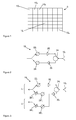
- FIGS 1 and 2 illustrate a schematic representation of a phased array antenna assembly 5.
- Each rectangle of Figure 1 represents a radiating antenna element 10 1 -10 n , where 'n' denotes the total number of radiating elements present in the phased array.
- Figure 2 is a basic representation of a module 15 i of the assembly 5.
- Each module 15 i comprises an element 10 i in combination with a power amplifier 20 i and a phase shifter 22 i , for transmitting a signal from the module 15 i via the radiating element 10 i .
- the phase shifter 22 i is used to establish a beam steering direction and the power amplifier 20 i is used to establish a correct input level for a module amplifier to operate with maximum efficiency.
- the signal Prior to transmission, the signal passes through a circulator 24 i which serves to separate "send” signals from “receive” signals.
- a so called “sum” beam is, thus, formed in free space in the desired direction.
- the outputs of the amplifiers of respective modules are saturated and, thus, give a uniform amplitude distribution across the array antenna assembly 5 for maximum transmit efficiency.
- a return signal received by element 10 i passes through circulator 24 i to a low noise amplifier 26 i and on to another phase shifter 28 i .
- the modules 15 i work in combination to form interrogating signals having particular characteristics, techniques generally referred to as beam forming and beam steering.
- the interrogating signal is typically transmitted as a narrow beam in a particular direction so as to define the approximate location of particular target.
- the range to the target is determined by timing the returned signal. It is desirable to be able to determine more accurately the particular bearing ( ⁇ ) and/or elevation (p) of the target.
- the approximate bearing ( ⁇ ) and elevation ( ⁇ ) of the target is known within a large tolerance as defined by an extent of an offset from a boresight of the interrogating signal. This offset represents the signal strength at a particular position in the beam width of the interrogating signal.
- a conventional method of more accurately determining the actual bearing ( ⁇ ) and elevation (p) of the target, within the beam, is to use a "monopulse" technique.
- each angle ( ⁇ , ⁇ ) is determined in a single measurement (hence monopulse) by using two beams rather than one in each plane of measurement.
- a single angle, the azimuth angle or bearing ( ⁇ ) is referred to but the discussion is equally applicable to angles of elevation (p).
- the first beam is a "sum beam” ( ⁇ ) and the second beam is a “difference beam” ( ⁇ )
- the beams are generated by associated sum and difference networks ( ⁇ , ⁇ ) within each module 15 i as illustrated in Figure 3 .
- the received signals are routed through the circulator 24 i to a low noise amplifier (LNA) 30 i , the signals are then split into two.
- a first signal continues through the sum beam network ( ⁇ ) where appropriate amplitude and phase values are applied using a variable amplifier 26 + i and a phase shifter 28 + i respectively, to form a received sum pattern.
- a second signal is routed through the difference beam network ( ⁇ ) where appropriate amplitude and phase values are applied using a variable amplifier 26 - i and a phase shifter 28 - i respectively, to form a received difference pattern.
- Composite sum ( ⁇ ) and difference ( ⁇ ) beams are formed by connecting RF signals to form sub-arrays for the outputs from each of the sum and difference beam forming networks, in this case at RF.
- Final sum and difference beams are then formed separately (after undergoing digital down conversion of the respective sub-array outputs) using appropriate digital summing networks.
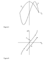
- the two beams may be plotted as shown in Figure 4 , the difference beam ( ⁇ ) being imposed onto a trace of the sum beam ( ⁇ ).
- the abscissa represents the azimuth ( ⁇ ) plot and is shown with the central datum representing the boresight.
- the ratio of the amplitudes of the two signals is unique. It so happens that the relationship between the ratio ( ⁇ / ⁇ ) and the azimuth angle ( ⁇ ) of the target or bearing, is quite linear as depicted in Figure 5 .
- This type of curve is hereinafter referred to as the ⁇ / ⁇ curve.
- the phased array antenna assembly 5 is provided with Built In Test Equipment (BITE) which serves to monitor the performance and characteristics of each and every module 15 i in the assembly 5.
- BITE Built In Test Equipment
- each module 15 i is tested and calibrated to ensure that the pattern shape, side lobes and phase shifter settings, also referred to as "base settings", required thereby are appropriate.
- Standard coefficients e.g. phase " ⁇ " and amplitude " a ", to be applied to each module 15 i during subsequent operation of the assembly are thereby generated. Once these standard coefficients ⁇ , a are applied to the received signals, the resulting output from each module defines a "standard template".
- the BITE monitoring facility is used at intervals to assess the current characteristics of each respective module 15 i on both send and receive and to compare these characteristics to the predetermined standard templates. If differences are identified, further investigations can be undertaken.
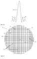
- Figure 6 represents a far field pattern from a fully operational antenna assembly 5 i.e. one not suffering from any failed modules 15 f .
- a "far field pattern” is a composite pattern made up from the output from each respective module 15 i of the antenna assembly 5.
- the main beam 32 is narrow and of high gain and the side lobes 34 are symmetrical and minimised.
- Figure 7 represents a substantially circular phased array antenna assembly 5 having a number of randomly failed modules 15 f .
- the number of failed modules 15 f increases, distortions in the far field pattern can be seen (as represented by Figure 8 ).
- the gain of the main beam 32' may be reduced and the main beam may, additionally, be broadened.
- the magnitude of the side lobes 34' may increase and the symmetry of the side lobes 34' may be destroyed.
- a ripple effect 36 may be experienced by the main beam 32'.
- This distortion is reflected in the ⁇ / ⁇ curve of Figure 5 in that the linearity of the trace deteriorates and the gradient ⁇ may be altered. Consequently, variations and distortions observed in the far field pattern and the ⁇ / ⁇ curve of Figure 5 , may be indicative of some failure in one or more components of the array assembly 5.
- the BITE functionality is used to calculate a far field pattern of an antenna array assembly 5 and to compare this pattern with a predetermined standard template. The comparison quantifies any variation from the standard template and assesses whether any such variation is within acceptable limits or not. BITE is also used to track the status of individual modules 15 i to ascertain whether they are functioning appropriately or whether any failure has occurred.
- the ⁇ / ⁇ curve is recalculated and linearity of the central portion of the curve (of Figure 5 ) is assessed by making a comparison with a standard template curve. If the comparisons show that any particular distortion is too severe, an optimisation, for example a Nelder-Mead Simplex method or a method of Steepest Descent, on the standard coefficients, e.g. phase ⁇ and amplitude a applied at the module level is carried out to generate modified coefficients ⁇ ', and a' used to compensate for any failed modules and return the far field pattern and monopulse patterns to acceptable limits.
- an optimisation for example a Nelder-Mead Simplex method or a method of Steepest Descent
- BITE is used to verify the acceptability of the new calibration and ensure that the patterns and curves approximate the original standard templates adequately.
- Parameters/characteristics such as antenna beam width, gain, side lobes in addition to the linearity and gradient of the ⁇ / ⁇ relationship are derived and used in the comparison and subsequent verification of the modified coefficients ⁇ ', a'.
- the phased array antenna assembly 5, represented by Figure 1 may comprise a multitude of radiating elements 10 i , for example in excess of 2000. Whilst it is possible to process signals received by each element during operation of the radar installation, to do so would be prohibitively expensive at present. Processing of received signals is, however, likely to be performed on such a basis in the future as conversion of analogue signals to digital signals becomes cheaper to undertake and the performance of computers further improves.
- Each sub-array 45 j has a receiver 50 j associated therewith which takes a combined, received analogue signal and converts it to a digital signal for further processing.
- the number, say N, of sub-arrays 45 j present in the phased array antenna assembly 5 is generally fixed. However the configuration of elements 10 i within any particular sub-array 45 j is typically not regular in pattern although each of the elements 10 i that form a sub-array 45 j are generally located adjacent to one another.
- a radar installation 40 having a phased array antenna assembly 5 formed from a number of sub-arrays 45 j may perform "digital adaptive beam forming" which can be used, for example, to counter jamming signals in the received signals. Signals in the sub-arrays 45 j are sampled and knowing when wanted signal returns would appear in the receivers, the unwanted jamming signals can be identified and minimised by changing weighting factors ⁇ j applied to each sub-array 45 j .
- FIG 10 illustrates a radar installation 40 in which a digital adaptive beam forming process is used.
- the installation 40 comprises a number of sub-arrays 45, three are shown in this example for illustrative purposes.
- Each sub-array 45 j has a receiver 50 j associated therewith.
- a returned signal, received by a sub-array 45 j is passed through the receiver 50 j , down-converted to in-phase and quadrature signals at a lower frequency and held in an associated buffer store 55 j while adaptive weighting factors ⁇ j are calculated as follows.
- a sample signal 60 is taken from each of the sub-arrays 45 j , clutter is removed by a filtering module 65 and the resulting filtered signal is then passed to a computer/processing module 70.
- the processing module 70 uses a noise minimisation algorithm to calculate a set of weighting factors ⁇ j . Such noise minimisation is carried out by forming simultaneous linear equations for the unknown weights. For each sample time, one equation expresses the requirement that the total noise received should be zero. Additional equations express requirements to maintain the antenna beam shape.
- the weighting factors ⁇ j are subsequently applied to the filtered signal to minimise any unwanted signals by modifying the phase and amplitude thereof.
- Each original signal is then retrieved from the respective buffer store 55 j and each sub-array value is multiplied by a respective weighting factor ⁇ j to produce a signal with a noise minimised output.
- FIG. 11 An example composite pattern 100 having three jamming signals 105 is illustrated in Figure 11 .
- the three jamming signals 105 dominate the pattern so that the desired signal 110, appearing in the main beam cannot be separated from the jamming signals 105.
- the modified composite pattern 100' (shown in Figure 121) formed by summing the individual weighted signals from respective sub-arrays 45 j exhibits nulls 115 in the direction of the jamming sources.
- the noise level in the receiver is, therefore, minimised enabling a desired signal 110 to be detected in the presence of the jamming signals.
- the overall composite pattern 100, 100', output from the summing module 75 may become distorted. If the main beam is particularly affected, distortions in one or both of the beams ( ⁇ and ⁇ ) will occur. The failure causes a ripple effect 36 in the far field pattern (see Figure 8 ) which may be minimal at the top of the trace representing the beam and more exaggerated at the bottom of the trace.
- This distortion of the, sum ( ⁇ ) and/or the difference ( ⁇ ) beam affects the ratio ( ⁇ / ⁇ ) and consequently affects the relationship of this ratio ( ⁇ / ⁇ ) to the target angle ( ⁇ ) illustrated in the graph of Figure 5 . As discussed above, it is desirable to retain the linearity of this relationship to enable the bearing angle ( ⁇ ) of the target to be ascertained.
- a far field pattern 100, 100' is output from the summing module 75.
- This pattern contains a, potentially severe, distortion in the main beam 32' and side lobes 34', due to failed elements 10 f or failed sub-array 45 f .
- Each sub-array 45 j contributes to the far field pattern 100, 100' in a known manner.
- the phase and amplitude of signals received by other elements 10 i or sub-arrays 45 j can be independently adjusted by modifying the standard coefficients of each respective module 15 i .
- the BITE functionality is used to calculate a far field pattern of an antenna array assembly 5' and this pattern is compared with a predetermined standard template. Additionally, a composite pattern at the sub-array level can be generated and compared to an equivalent plot (standard template) generated when the sub-array 45 j was fully functional (prior to any failures). Such a comparison enables any variation from the standard template to be quantified thus enabling an assessment regarding whether any such variation is within acceptable limits or not.
- BITE is also used to track the status of individual modules 15 j to ascertain whether they are functioning appropriately or whether any failure has occurred. BITE may also be used at the sub-array level to track an equivalent status of each and every sub-array 45 j .
- the ⁇ / ⁇ curve is recalculated and linearity of the central portion of the curve (of Figure 5 ) is assessed by making a comparison with a standard template curve. If the comparisons show that any particular distortion is too severe, an optimisation, a Nelder-Mead Simplex method or a method of Steepest Descent, on the standard coefficients, e.g. phase ⁇ and amplitude a applied at the module level is carried out to compensate for any failed modules 15 f and return the far field pattern and monopulse patterns to acceptable limits.
- a Nelder-Mead Simplex method or a method of Steepest Descent on the standard coefficients, e.g. phase ⁇ and amplitude a applied at the module level is carried out to compensate for any failed modules 15 f and return the far field pattern and monopulse patterns to acceptable limits.
- the optimisation may be applied to all modules 15 i or sub-arrays 45 j across the antenna assembly 5' or, alternatively, just to certain sub-arrays.
- Figures 14 to 16 illustrate possible applications of the technique to sub-arrays 45 m in a substantially circular phased array antenna assembly 5' experiencing a failed sub-array 45 f .
- the sub-arrays 45 m to which the adjusted values of phase ⁇ and amplitude a are applied may be those directly adjacent to the failed sub-array 45 f as illustrated in Figure 14 .
- the, or each, sub-array 45 m to be modified may be located remotely from the failed sub-array 45 f in a balanced manner.
- the sub-array 45 m to be modified is located the same distance, D, D', from a central axis, P, Q, of the installation 5' as the failed sub-array 45 f .
- each and every sub-array 45 j of the phased array antenna assembly 5' may be subject to a corresponding adjusted phase ⁇ and amplitude a parameters (not shown).
- a library or set of rules can be established whereby certain failures respond well to modification of certain sub-arrays 45 m . In so doing, future modes of failure of the antenna assembly 5' can be addressed and compensated for more rapidly.
- BITE is used to verify the acceptability of the new calibration and ensure that the patterns and curves approximate the original standard templates adequately.
- Parameters/characteristics such as antenna beam width, gain, side lobes in addition to the linearity and gradient of the ⁇ / ⁇ relationship are derived and used in the comparison/verification of modified coefficients.
- the antenna is reset with modified phase ⁇ and amplitude a values which are setup after the optimisation process has been completed.
- the optimisation is to be performed in real time but in this embodiment, operation of the radar installation would be stopped to carry out the phase ⁇ and amplitude a correction process, the process being completed prior to re-initiation of the radar.
- the pattern 100, 100' is artificially adjusted.
- the contribution from particular elements 10 i and/or sub-arrays 45 j may be reduced to zero using the coefficients ⁇ , a or by withdrawal of power to said elements 10 i and/or sub-arrays 45 j .
- the optimisation results in a modified far field pattern 100" (not illustrated) that approximates the original composite far field pattern 100, 100'. In so doing, failure of one or more elements 10 f or sub-arrays 45 f may lead to broadening of the beam but retention of the linear relationship of the ⁇ / ⁇ curve.
- Digital adaptive beam forming where used, continues to operate and adapt to remove jamming signals as described above, using the newly calculated phase ⁇ and amplitude a values.
Landscapes
- Engineering & Computer Science (AREA)
- Radar, Positioning & Navigation (AREA)
- Remote Sensing (AREA)
- Computer Networks & Wireless Communication (AREA)
- Physics & Mathematics (AREA)
- General Physics & Mathematics (AREA)
- Radar Systems Or Details Thereof (AREA)
- Variable-Direction Aerials And Aerial Arrays (AREA)
Abstract
A method for compensating for the failure of an element in a phased array antenna assembly is provided.
After failure of an element of the assembly, a composite pattern is generated from signals received by respective elements in the antenna assembly. This generated pattern is then compared to a standard composite pattern which was generated prior to the failure. Thus the necessity for remedial action can be assessed.
If necessary, initial values for parameters associated with each element are assumed and an optimisation is performed on the parameters. Consequently, a composite pattern can be generated which approximates the standard composite pattern. Once optimisation has been achieved, the optimised parameters are applied to base settings for the assembly and operation of the phased array antenna assembly can be continued.
Description
- The present invention relates to radar installations comprising an active phased array antenna assembly. In particular, it relates to a method for compensating for the failure of one or more elements of such an installation.
- In a passive array, a single transmitter and receiver are connected to an antenna via transmission lines that incur significant RF loss. In an active array, each of a number of radiating elements is connected directly to a transmit/receive unit (TRU) to minimise RF losses between the antenna, a final stage power amplifier of the transmitter and the receiver. This architecture significantly reduces RF losses improving the system over that of a passive array system.
- Active phased arrays are frequently used in applications where several thousand modules form the array. Each module comprises an antenna element and a transmit/receive unit (TRU). Failure of a single module makes an insignificant difference to radar performance when the single module is one in, say, several thousand. As the number of module failures increases, the performance of the array gradually degrades due to an associated loss in transmit power. Furthermore, consequential irregularities in the antenna amplitude distribution, raises side lobes and can cause beam distortion and loss of gain. Failure of up to 5% of the modules can be tolerated if the failures are randomly distributed across the array face. Designing the array with an excess of, say, 5% more modules than the number needed to achieve a specified performance enables the array to continue to operate within the specification until more than 5% of the modules have failed.
- In some applications, groups of modules are connected together on receive to form sub-arrays. The output from each sub-array is down converted to an intermediate frequency (IF) or to a digital signal and can then be used to adaptively change the antenna pattern as a means of countering barrage and pulse noise jamming. The use of sub-array groupings makes the array more vulnerable to failure if, for instance, a number of modules in a sub-array were to fail or if the sub-array receiver failed. Failure of a significant proportion of the modules in a single sub-array has a noticeable distorting effect on a received formed beam. Gain of the formed beam and therefore the detection performance and accuracy of an angle measurement associated with the beam is, consequently, reduced.
- It is desirable to minimise the impact of the failure of any such modules or sub-arrays of said modules.
- According to a first aspect, the present invention provides a method for compensating for the failure of an element in a phased array antenna assembly, the method comprising the steps of:
- a) generating a composite pattern from signals received by respective elements in the antenna assembly after failure of an element of the assembly;
- b) comparing the pattern to a standard composite pattern generated prior to the failure to assess necessity for remedial action;
- c) assuming initial values for parameters associated with each element;
- d) performing optimisation on the parameters to generate a composite pattern which approximates the standard composite pattern;
- e) applying optimised parameters to base settings for the assembly; and
- f) continuing with operation of the phased array antenna assembly.
- By providing a method for compensating for the failure of an element in a phased array antenna assembly, operation of the assembly can be continued with little or no down time for the period in which replacement of the failed components are sourced and a corresponding maintenance task is scheduled. In particular, by optimising standard parameters associated with each element and modifying the base settings for the assembly accordingly, based on output from the assembly, a robust compensation method can be achieved that substantially approximates the normal operation of the antenna assembly prior to such a failure occurring.
- The optimisation step (d) may comprise the steps of (i) generating a modified composite pattern based on the optimised parameters; and (ii) comparing the modified pattern to the standard pattern to assess whether acceptable performance is achieved.
- The generating steps (a) and (i) may comprise generating a monopulse pattern for the entire antenna array assembly and the comparing steps b) and ii) may comprise comparing the monopulse pattern with a standard monopulse pattern generated prior to the failure, in addition to assessing any variation in the, or each, composite pattern from a standard composite pattern. The optimisation step (d) may, therefore, also use the monopulse pattern in addition to the composite pattern.
- The generating steps (a) and (i) may comprise generating a curve of antenna pattern difference/sum ratio (Δ/Σ) plotted against offset angle α, hereinafter referred to as the Δ/Σ curve, for the entire antenna array assembly and the comparing steps (b) and (ii) may comprise comparing the Δ/Σ curve with a standard Δ/Σ curve generated prior to the failure, in addition to assessing any variation in the, or each, composite pattern from a standard composite pattern. The optimisation step (d) may, therefore, also use the Δ/Σ curve in addition to the composite pattern.
- The parameters may be phase and amplitude.
- The element may be an antenna element or it may be a module comprising an antenna element. Alternatively, the element may be a sub-array comprising at least one module, the, or each, module may comprise an antenna element and the, or each, parameter may be associated with the, or each, module of the sub-array.
- The applying step (e) may apply modified parameters to modules in selected sub-arrays of the assembly. The modified parameters may be applied to sub-arrays located directly adjacent to the failed sub-array or, alternatively, the modified parameters may be applied to sub-arrays located remotely from the failed sub-array in a balanced manner. The applying step (e) may apply modified parameters to modules in all sub-arrays of the assembly. Characteristics of the failure together with a location of the, or each, sub-array to which modified parameters are applied may be recorded in a library and the method may comprise a step of interrogating the library to ascertain the sub-arrays to which modified parameters are to be applied.
- The generating step (a) may be undertaken during a routine monitoring process. The method may comprise a step of monitoring phase and amplitude of composite patterns generated in generating step (a) to detect failure of an element. The method may comprise a step of calculating standard patterns and/or curves, prior to failure.
- According to a second aspect, the present invention provides a phased array antenna assembly comprising:
- a plurality of modules, each module comprising an antenna element; and
- a controller, for controlling the antenna assembly, configured to perform the aforementioned method.
- According to a third aspect, the present invention provides a radar installation comprising a phased array antenna assembly of the aforementioned type.
- The present invention will now be described in more detail, by way of example only, with reference to the accompanying drawings in which:
-
Figure 1 shows a schematic representation of a phased array antenna assembly; -
Figure 2 shows a basic schematic representation of a transmit/receive module of the phased array ofFigure 1 ; -
Figure 3 shows a more sophisticated schematic representation of a transmit/receive module ofFigure 1 ; -
Figure 4 shows a graphical representation of two signals received by the installation represented inFigure 3 ; -
Figure 5 shows a graphical representation of a relationship between the plots ofFigure 4 ; -
Figure 6 represents a far field pattern from an antenna assembly without failed modules or sub-arrays; -
Figure 7 illustrates a substantially circular phased array antenna assembly with randomly failed modules; -
Figure 8 represents a far field pattern from an antenna assembly having some failed modules or sub-array(s); -
Figure 9 shows a schematic representation of a phased array antenna assembly comprising a number of sub-arrays; -
Figure 10 shows a schematic representation of three sub-arrays used in a digital adaptive beam forming process; -
Figure 11 shows a returned signal representing a target and several jamming signals; -
Figure 12 shows the signal ofFigure 8 after processing; -
Figure 13 represents the phased array antenna assembly shown inFigure 9 with a failed sub-array; -
Figure 14 represents a first proposal for compensating for a failed sub-array in a substantially circular phased array antenna assembly; -
Figure 15 represents a second proposal for compensating for a failed sub-array in a substantially circular phased array antenna assembly; and -
Figure 16 represents a third proposal for compensating for a failed sub-array in a substantially circular phased array antenna assembly. -
Figures 1 and 2 illustrate a schematic representation of a phasedarray antenna assembly 5. Each rectangle ofFigure 1 represents a radiating antenna element 101-10n, where 'n' denotes the total number of radiating elements present in the phased array.Figure 2 is a basic representation of amodule 15i of theassembly 5. Eachmodule 15i comprises anelement 10i in combination with a power amplifier 20i and aphase shifter 22i, for transmitting a signal from themodule 15i via the radiatingelement 10i. Thephase shifter 22i is used to establish a beam steering direction and the power amplifier 20i is used to establish a correct input level for a module amplifier to operate with maximum efficiency. - Prior to transmission, the signal passes through a
circulator 24i which serves to separate "send" signals from "receive" signals. A so called "sum" beam is, thus, formed in free space in the desired direction. In this example, the outputs of the amplifiers of respective modules are saturated and, thus, give a uniform amplitude distribution across thearray antenna assembly 5 for maximum transmit efficiency. - A return signal received by
element 10i passes throughcirculator 24i to alow noise amplifier 26i and on to anotherphase shifter 28i. Themodules 15i work in combination to form interrogating signals having particular characteristics, techniques generally referred to as beam forming and beam steering. - In a phased array, the interrogating signal is typically transmitted as a narrow beam in a particular direction so as to define the approximate location of particular target. The range to the target is determined by timing the returned signal. It is desirable to be able to determine more accurately the particular bearing (α) and/or elevation (p) of the target. The approximate bearing (α) and elevation (β) of the target is known within a large tolerance as defined by an extent of an offset from a boresight of the interrogating signal. This offset represents the signal strength at a particular position in the beam width of the interrogating signal.
- A conventional method of more accurately determining the actual bearing (α) and elevation (p) of the target, within the beam, is to use a "monopulse" technique. In other words, each angle (α,β) is determined in a single measurement (hence monopulse) by using two beams rather than one in each plane of measurement. Hereinafter, a single angle, the azimuth angle or bearing (α) is referred to but the discussion is equally applicable to angles of elevation (p).
- Of the two received beams, the first beam is a "sum beam" (Σ) and the second beam is a "difference beam" (Δ), the beams are generated by associated sum and difference networks (Σ, Δ) within each
module 15i as illustrated inFigure 3 . The received signals are routed through thecirculator 24i to a low noise amplifier (LNA) 30i, the signals are then split into two. A first signal continues through the sum beam network (Σ) where appropriate amplitude and phase values are applied using avariable amplifier 26+ i and aphase shifter 28+ i respectively, to form a received sum pattern. A second signal is routed through the difference beam network (Δ) where appropriate amplitude and phase values are applied using avariable amplifier 26- i and aphase shifter 28- i respectively, to form a received difference pattern. - Composite sum (Σ) and difference (Δ) beams are formed by connecting RF signals to form sub-arrays for the outputs from each of the sum and difference beam forming networks, in this case at RF. Final sum and difference beams are then formed separately (after undergoing digital down conversion of the respective sub-array outputs) using appropriate digital summing networks.
- The two beams may be plotted as shown in
Figure 4 , the difference beam (Δ) being imposed onto a trace of the sum beam (Σ). The abscissa represents the azimuth (α) plot and is shown with the central datum representing the boresight. At any particular angle, represented along the abscissa, the ratio of the amplitudes of the two signals (the difference beam (Δ)/sum beam (Σ)) is unique. It so happens that the relationship between the ratio (Δ/Σ) and the azimuth angle (α) of the target or bearing, is quite linear as depicted inFigure 5 . This type of curve is hereinafter referred to as the Δ/Σ curve. As the sum signal (Σ) approaches zero (as shown inFigure 4 ) the trace of the ratio varying with angle tends to infinity. It follows that the linear relationship (having a gradient λ) extends to approximately the width of the primary beam of the sum signal. The linearity of this curve enables the bearing α of the target to be readily ascertained. - In the present embodiment, the phased
array antenna assembly 5 is provided with Built In Test Equipment (BITE) which serves to monitor the performance and characteristics of each and everymodule 15i in theassembly 5. Upon manufacture and/or installation of theassembly 5, eachmodule 15i is tested and calibrated to ensure that the pattern shape, side lobes and phase shifter settings, also referred to as "base settings", required thereby are appropriate. Standard coefficients, e.g. phase "φ" and amplitude "a", to be applied to eachmodule 15i during subsequent operation of the assembly are thereby generated. Once these standard coefficients φ, a are applied to the received signals, the resulting output from each module defines a "standard template". - In operation, the BITE monitoring facility is used at intervals to assess the current characteristics of each
respective module 15i on both send and receive and to compare these characteristics to the predetermined standard templates. If differences are identified, further investigations can be undertaken. -
Figure 6 represents a far field pattern from a fullyoperational antenna assembly 5 i.e. one not suffering from any failedmodules 15f. A "far field pattern" is a composite pattern made up from the output from eachrespective module 15i of theantenna assembly 5. Themain beam 32 is narrow and of high gain and theside lobes 34 are symmetrical and minimised. -
Figure 7 represents a substantially circular phasedarray antenna assembly 5 having a number of randomly failedmodules 15f. As the number of failedmodules 15f increases, distortions in the far field pattern can be seen (as represented byFigure 8 ). For example, the gain of the main beam 32' may be reduced and the main beam may, additionally, be broadened. The magnitude of the side lobes 34' may increase and the symmetry of the side lobes 34' may be destroyed. Furthermore, aripple effect 36 may be experienced by the main beam 32'. This distortion is reflected in the Δ/Σ curve ofFigure 5 in that the linearity of the trace deteriorates and the gradient λ may be altered. Consequently, variations and distortions observed in the far field pattern and the Δ/Σ curve ofFigure 5 , may be indicative of some failure in one or more components of thearray assembly 5. - The BITE functionality is used to calculate a far field pattern of an
antenna array assembly 5 and to compare this pattern with a predetermined standard template. The comparison quantifies any variation from the standard template and assesses whether any such variation is within acceptable limits or not. BITE is also used to track the status ofindividual modules 15i to ascertain whether they are functioning appropriately or whether any failure has occurred. - The Δ/Σ curve is recalculated and linearity of the central portion of the curve (of
Figure 5 ) is assessed by making a comparison with a standard template curve. If the comparisons show that any particular distortion is too severe, an optimisation, for example a Nelder-Mead Simplex method or a method of Steepest Descent, on the standard coefficients, e.g. phase φ and amplitude a applied at the module level is carried out to generate modified coefficients φ', and a' used to compensate for any failed modules and return the far field pattern and monopulse patterns to acceptable limits. - BITE is used to verify the acceptability of the new calibration and ensure that the patterns and curves approximate the original standard templates adequately. Parameters/characteristics such as antenna beam width, gain, side lobes in addition to the linearity and gradient of the Δ/Σ relationship are derived and used in the comparison and subsequent verification of the modified coefficients φ', a'.
- Once suitable modified coefficients (e.g. φ, a') have been ascertained these are substituted for the original values (e.g. φ, a) in the base settings of each
respective module 15i to achieve an acceptable overall antenna performance during normal operation. - Finally, normal operation of the antenna installation is continued and BITE continues to undertake regular checks to ensure that the new settings yield acceptable results.
- The phased
array antenna assembly 5, represented byFigure 1 , may comprise a multitude of radiatingelements 10i, for example in excess of 2000. Whilst it is possible to process signals received by each element during operation of the radar installation, to do so would be prohibitively expensive at present. Processing of received signals is, however, likely to be performed on such a basis in the future as conversion of analogue signals to digital signals becomes cheaper to undertake and the performance of computers further improves. - As a compromise, it is known for the multitude of
elements 10i to be grouped together to form a smaller number of sub-arrays 45j (j=1 to N) as illustrated inFigure 9 . Each sub-array 45j has areceiver 50j associated therewith which takes a combined, received analogue signal and converts it to a digital signal for further processing. - The number, say N, of sub-arrays 45j present in the phased
array antenna assembly 5 is generally fixed. However the configuration ofelements 10i within anyparticular sub-array 45j is typically not regular in pattern although each of theelements 10i that form a sub-array 45j are generally located adjacent to one another. - A
radar installation 40, having a phasedarray antenna assembly 5 formed from a number ofsub-arrays 45j may perform "digital adaptive beam forming" which can be used, for example, to counter jamming signals in the received signals. Signals in the sub-arrays 45j are sampled and knowing when wanted signal returns would appear in the receivers, the unwanted jamming signals can be identified and minimised by changing weighting factors ωj applied to each sub-array 45j. -
Figure 10 illustrates aradar installation 40 in which a digital adaptive beam forming process is used. Theinstallation 40 comprises a number ofsub-arrays 45, three are shown in this example for illustrative purposes. Each sub-array 45j has areceiver 50j associated therewith. A returned signal, received by a sub-array 45j, is passed through thereceiver 50j, down-converted to in-phase and quadrature signals at a lower frequency and held in an associatedbuffer store 55j while adaptive weighting factors ωj are calculated as follows. - A
sample signal 60 is taken from each of the sub-arrays 45j, clutter is removed by afiltering module 65 and the resulting filtered signal is then passed to a computer/processing module 70. Theprocessing module 70 uses a noise minimisation algorithm to calculate a set of weighting factors ωj. Such noise minimisation is carried out by forming simultaneous linear equations for the unknown weights. For each sample time, one equation expresses the requirement that the total noise received should be zero. Additional equations express requirements to maintain the antenna beam shape. - The entire system of equations cannot be solved exactly because it is over-determined; there are more equations than unknown weights. However, an approximate solution can be obtained in a least-squares sense by forming the covariance matrix of the equation system coefficients and solving the resulting reduced system of equations.
- The weighting factors ωj are subsequently applied to the filtered signal to minimise any unwanted signals by modifying the phase and amplitude thereof. Each original signal is then retrieved from the
respective buffer store 55j and each sub-array value is multiplied by a respective weighting factor ωj to produce a signal with a noise minimised output. - Individual signals from the respective sub-arrays 45j are then summed to form a modified composite pattern 100' using a summing
module 75. - An example
composite pattern 100 having three jammingsignals 105 is illustrated inFigure 11 . The threejamming signals 105 dominate the pattern so that the desiredsignal 110, appearing in the main beam cannot be separated from the jamming signals 105. - By using the digital adaptive beam forming process described above, the modified composite pattern 100' (shown in Figure 121) formed by summing the individual weighted signals from respective sub-arrays 45j exhibits nulls 115 in the direction of the jamming sources. The noise level in the receiver is, therefore, minimised enabling a desired
signal 110 to be detected in the presence of the jamming signals. - If one
sub-array 45f, or a number ofelements 10f, experiences failure as represented byFigure 13 , the overallcomposite pattern 100, 100', output from the summingmodule 75, may become distorted. If the main beam is particularly affected, distortions in one or both of the beams (Δ and Σ) will occur. The failure causes aripple effect 36 in the far field pattern (seeFigure 8 ) which may be minimal at the top of the trace representing the beam and more exaggerated at the bottom of the trace. This distortion of the, sum (Σ) and/or the difference (Δ) beam affects the ratio (Δ/Σ) and consequently affects the relationship of this ratio (Δ/Σ) to the target angle (α) illustrated in the graph ofFigure 5 . As discussed above, it is desirable to retain the linearity of this relationship to enable the bearing angle (α) of the target to be ascertained. - Implementation of an antenna performance optimisation technique, described above at an element level, aims to maintain a linear relationship between the two signals Δ, Σ. The technique can readily be applied at the sub-array level too.
- A
far field pattern 100, 100' is output from the summingmodule 75. This pattern contains a, potentially severe, distortion in the main beam 32' and side lobes 34', due to failedelements 10f or failedsub-array 45f. Each sub-array 45j contributes to thefar field pattern 100, 100' in a known manner. The phase and amplitude of signals received byother elements 10i or sub-arrays 45j can be independently adjusted by modifying the standard coefficients of eachrespective module 15i. - Once again, the BITE functionality is used to calculate a far field pattern of an antenna array assembly 5' and this pattern is compared with a predetermined standard template. Additionally, a composite pattern at the sub-array level can be generated and compared to an equivalent plot (standard template) generated when the sub-array 45j was fully functional (prior to any failures). Such a comparison enables any variation from the standard template to be quantified thus enabling an assessment regarding whether any such variation is within acceptable limits or not. As before, BITE is also used to track the status of
individual modules 15j to ascertain whether they are functioning appropriately or whether any failure has occurred. BITE may also be used at the sub-array level to track an equivalent status of each and every sub-array 45j. - The Δ/Σ curve is recalculated and linearity of the central portion of the curve (of
Figure 5 ) is assessed by making a comparison with a standard template curve. If the comparisons show that any particular distortion is too severe, an optimisation, a Nelder-Mead Simplex method or a method of Steepest Descent, on the standard coefficients, e.g. phase φ and amplitude a applied at the module level is carried out to compensate for any failedmodules 15f and return the far field pattern and monopulse patterns to acceptable limits. - The optimisation may be applied to all
modules 15i orsub-arrays 45j across the antenna assembly 5' or, alternatively, just to certain sub-arrays. -
Figures 14 to 16 illustrate possible applications of the technique to sub-arrays 45m in a substantially circular phased array antenna assembly 5' experiencing a failedsub-array 45f. - The sub-arrays 45m to which the adjusted values of phase φ and amplitude a are applied may be those directly adjacent to the failed sub-array 45f as illustrated in
Figure 14 . In contrast, the, or each, sub-array 45m to be modified may be located remotely from the failed sub-array 45f in a balanced manner. In the examples shown inFigures 15 and 16 , the sub-array 45m to be modified is located the same distance, D, D', from a central axis, P, Q, of the installation 5' as the failedsub-array 45f. Alternatively, each and everysub-array 45j of the phased array antenna assembly 5' may be subject to a corresponding adjusted phase φ and amplitude a parameters (not shown). - A library or set of rules can be established whereby certain failures respond well to modification of certain sub-arrays 45m. In so doing, future modes of failure of the antenna assembly 5' can be addressed and compensated for more rapidly.
- BITE is used to verify the acceptability of the new calibration and ensure that the patterns and curves approximate the original standard templates adequately. Parameters/characteristics such as antenna beam width, gain, side lobes in addition to the linearity and gradient of the Δ/Σ relationship are derived and used in the comparison/verification of modified coefficients.
- Once suitable modified coefficients have been ascertained these are substituted for the original values (e.g. of phase φ and amplitude a) in the settings of each module to achieve overall antenna performance during normal operation.
- Finally, normal operation of the antenna installation is continued and BITE continues to undertake regular checks to ensure that the new settings yield acceptable results.
- The antenna is reset with modified phase φ and amplitude a values which are setup after the optimisation process has been completed. Ultimately, it is anticipated that the optimisation is to be performed in real time but in this embodiment, operation of the radar installation would be stopped to carry out the phase φ and amplitude a correction process, the process being completed prior to re-initiation of the radar. Thus, the
pattern 100, 100' is artificially adjusted. - In the extreme, the contribution from
particular elements 10i and/or sub-arrays 45j may be reduced to zero using the coefficients φ, a or by withdrawal of power to saidelements 10i and/orsub-arrays 45j. In either case, the optimisation results in a modifiedfar field pattern 100" (not illustrated) that approximates the original compositefar field pattern 100, 100'. In so doing, failure of one ormore elements 10f or sub-arrays 45f may lead to broadening of the beam but retention of the linear relationship of the Δ/Σ curve. - Digital adaptive beam forming, where used, continues to operate and adapt to remove jamming signals as described above, using the newly calculated phase φ and amplitude a values.
Claims (15)
- A method for compensating for the failure of an element in a phased array antenna assembly, the method comprising the steps of:a) generating a composite pattern from signals received by respective elements in the antenna assembly after failure of an element of the assembly;b) comparing the pattern to a standard composite pattern generated prior to the failure to assess necessity for remedial action;c) assuming initial values for parameters associated with each element;d) performing optimisation on the parameters to generate a composite pattern which approximates the standard composite pattern;e) applying optimised parameters to base settings for the assembly; andf) continuing with operation of the phased array antenna assembly.
- A method according to Claim 1, wherein the optimisation step comprises the steps of:i) generating a modified composite pattern based on the optimised parameters; andii) comparing the modified pattern to the standard pattern to assess whether acceptable performance is achieved.
- A method according to Claim 2, wherein the generating steps a) and i) comprise generating a monopulse pattern for the entire antenna array assembly and the comparing steps b) and ii) comprise comparing the monopulse pattern with a standard monopulse pattern generated prior to the failure, in addition to assessing a variation in the, or each, composite pattern.
- A method according to Claim 3, wherein the optimisation step d) uses the monopulse pattern in addition to the composite pattern.
- A method according to any of Claims 2 to 4, wherein the generating steps a) and i) comprise generating a curve of antenna pattern difference/sum ratio (Δ/Σ) plotted against offset angle (α) for the entire antenna array assembly and the comparing steps b) and ii) comprise comparing the Δ/Σ curve with a standard Δ/Σ curve generated prior to the failure, in addition to assessing a variation in the, or each, composite pattern.
- A method according to Claim 5, wherein the optimisation step d) uses the Δ/Σ curve in addition to the composite pattern.
- A method according to any of Claims 1 to 6, wherein the element is a sub-array comprising at least one module, the, or each, module comprising an antenna element and the, or each, parameter being associated with the, or each, module of the sub-array.
- A method according to Claim 7, wherein the applying step e) applies modified parameters to modules in selected sub-arrays of the assembly.
- A method according to Claim 8, wherein the modified parameters are applied to sub-arrays located directly adjacent to the failed sub-array.
- A method according to Claim 8, wherein the modified parameters are applied to sub-arrays located remotely from the failed sub-array in a balanced manner.
- A method according to Claim 7, wherein the applying step e) applies modified parameters to modules in all sub-arrays of the assembly.
- A method according to any of Claims 8 to 11, wherein characteristics of the failure together with a location of the, or each, sub-array to which modified parameters are applied is recorded in a library.
- A method according to Claim 12, comprising a step of interrogating the library to ascertain the sub-arrays to which modified parameters are to be applied.
- A method according to any preceding claim, wherein the generating step a) is undertaken during a routine monitoring process and comprising a step of monitoring phase and amplitude of composite patterns generated in generating step a) to detect failure of an element.
- A phased array antenna assembly comprising:a plurality of modules, each module comprising an antenna element; anda controller, for controlling the antenna assembly, configured to perform a method according to any preceding claim.
Priority Applications (4)
| Application Number | Priority Date | Filing Date | Title |
|---|---|---|---|
| EP09275073A EP2296223A1 (en) | 2009-09-09 | 2009-09-09 | Antenna failure compensation |
| EP10752379.7A EP2476163B1 (en) | 2009-09-09 | 2010-09-02 | Antenna failure compensation |
| PCT/GB2010/051449 WO2011030125A1 (en) | 2009-09-09 | 2010-09-02 | Antenna failure compensation |
| US13/395,032 US8907845B2 (en) | 2009-09-09 | 2010-09-02 | Antenna failure compensation |
Applications Claiming Priority (1)
| Application Number | Priority Date | Filing Date | Title |
|---|---|---|---|
| EP09275073A EP2296223A1 (en) | 2009-09-09 | 2009-09-09 | Antenna failure compensation |
Publications (1)
| Publication Number | Publication Date |
|---|---|
| EP2296223A1 true EP2296223A1 (en) | 2011-03-16 |
Family
ID=41165476
Family Applications (1)
| Application Number | Title | Priority Date | Filing Date |
|---|---|---|---|
| EP09275073A Ceased EP2296223A1 (en) | 2009-09-09 | 2009-09-09 | Antenna failure compensation |
Country Status (1)
| Country | Link |
|---|---|
| EP (1) | EP2296223A1 (en) |
Cited By (4)
| Publication number | Priority date | Publication date | Assignee | Title |
|---|---|---|---|---|
| CN113468808A (en) * | 2021-06-29 | 2021-10-01 | 西安电子科技大学 | Deformed array antenna electrical property compensation method based on subarray extrapolation and phase optimization |
| CN114336089A (en) * | 2021-12-15 | 2022-04-12 | 南京理工大学 | A Hierarchical Design Method for Large-Scale Wide-Angle Scanning Phased Array Antennas |
| CN115224490A (en) * | 2021-04-20 | 2022-10-21 | 南通先进通信技术研究院有限公司 | A method for optimization of phased array multi-beam scheduling based on maritime communication |
| CN115712096A (en) * | 2022-11-14 | 2023-02-24 | 北京无线电测量研究所 | Initial phase compensation method, system, medium and device for subarray-level finite phase interval |
Citations (4)
| Publication number | Priority date | Publication date | Assignee | Title |
|---|---|---|---|---|
| US5083131A (en) * | 1990-05-31 | 1992-01-21 | Hughes Aircraft Company | Local compensation of failed elements of an active antenna array |
| US5559519A (en) * | 1995-05-04 | 1996-09-24 | Northrop Grumman Corporation | Method and system for the sequential adaptive deterministic calibration of active phased arrays |
| US6140976A (en) * | 1999-09-07 | 2000-10-31 | Motorola, Inc. | Method and apparatus for mitigating array antenna performance degradation caused by element failure |
| US6339398B1 (en) * | 1999-03-12 | 2002-01-15 | Telefonaktiebolaget Lm Ericsson | Compensation of faulty elements in array antennas |
-
2009
- 2009-09-09 EP EP09275073A patent/EP2296223A1/en not_active Ceased
Patent Citations (4)
| Publication number | Priority date | Publication date | Assignee | Title |
|---|---|---|---|---|
| US5083131A (en) * | 1990-05-31 | 1992-01-21 | Hughes Aircraft Company | Local compensation of failed elements of an active antenna array |
| US5559519A (en) * | 1995-05-04 | 1996-09-24 | Northrop Grumman Corporation | Method and system for the sequential adaptive deterministic calibration of active phased arrays |
| US6339398B1 (en) * | 1999-03-12 | 2002-01-15 | Telefonaktiebolaget Lm Ericsson | Compensation of faulty elements in array antennas |
| US6140976A (en) * | 1999-09-07 | 2000-10-31 | Motorola, Inc. | Method and apparatus for mitigating array antenna performance degradation caused by element failure |
Non-Patent Citations (7)
| Title |
|---|
| ARUN K. BHATTACHARYYA: "Phased Array Antennas", 2005, WILEY-INTERSCIENCE, Hoboken, NJ, ISBN: 0471727571, XP002551989 * |
| KEIZER W P N: "Element Failure Correction for a Large Monopulse Phased Array Antenna With Active Amplitude Weighting", IEEE TRANSACTIONS ON ANTENNAS AND PROPAGATION, IEEE SERVICE CENTER, PISCATAWAY, NJ, US, vol. 55, no. 8, 1 August 2007 (2007-08-01), pages 2211 - 2218, XP011189666, ISSN: 0018-926X * |
| MENACHEM LEVITAS ET AL: "Practical Failure Compensation in Active Phased Arrays", IEEE TRANSACTIONS ON ANTENNAS AND PROPAGATION, IEEE SERVICE CENTER, PISCATAWAY, NJ, US, vol. 47, no. 3, 1 March 1999 (1999-03-01), XP011003492, ISSN: 0018-926X * |
| PETERS T J: "A CONJUGATE GRADIENT-BASED ALGORITHM TO MINIMIZE THE SIDELOBE LEVEL OF PLANAR ARRAYS WITH ELEMENT FAILURES", IEEE TRANSACTIONS ON ANTENNAS AND PROPAGATION, IEEE SERVICE CENTER, PISCATAWAY, NJ, US, vol. 39, no. 10, 1 October 1991 (1991-10-01), pages 1497 - 1504, XP000234575, ISSN: 0018-926X * |
| REDVIK J: "Simulated annealing optimization applied to antenna arrays with failed elements", ANTENNAS AND PROPAGATION SOCIETY, 1999. IEEE INTERNATIONAL SYMPOSIUM 1 999 ORLANDO, FL, USA 11-16 JULY 1999, PISCATAWAY, NJ, USA,IEEE, US, vol. 1, 11 July 1999 (1999-07-11), pages 458 - 461, XP010348214, ISBN: 9780780356399 * |
| STEYSKAL H ET AL: "Generalisation of an array-failure-correction method", IEE PROCEEDINGS: MICROWAVES, ANTENNAS AND PROPAGATION, IEE, STEVENAGE, HERTS, GB, vol. 145, no. 4, 10 August 1998 (1998-08-10), pages 332 - 336, XP006011290, ISSN: 1350-2417 * |
| WRIGHT P J ET AL: "Re-optimisation of linear and planar arrays with failed elements", ANTENNAS AND PROPAGATION, 1995., NINTH INTERNATIONAL CONFERENCE ON (CO NF. PUBL. NO. 407) EINDHOVEN, NETHERLANDS, LONDON, UK,IEE, UK, 1 January 1995 (1995-01-01), pages 81 - 84, XP006528108, ISBN: 9780852966372 * |
Cited By (6)
| Publication number | Priority date | Publication date | Assignee | Title |
|---|---|---|---|---|
| CN115224490A (en) * | 2021-04-20 | 2022-10-21 | 南通先进通信技术研究院有限公司 | A method for optimization of phased array multi-beam scheduling based on maritime communication |
| CN113468808A (en) * | 2021-06-29 | 2021-10-01 | 西安电子科技大学 | Deformed array antenna electrical property compensation method based on subarray extrapolation and phase optimization |
| CN113468808B (en) * | 2021-06-29 | 2024-03-22 | 西安电子科技大学 | Deformation array antenna electrical performance compensation method based on subarray extrapolation and phase optimization |
| CN114336089A (en) * | 2021-12-15 | 2022-04-12 | 南京理工大学 | A Hierarchical Design Method for Large-Scale Wide-Angle Scanning Phased Array Antennas |
| CN114336089B (en) * | 2021-12-15 | 2024-03-19 | 南京理工大学 | A hierarchical design method for large-scale wide-angle scanning phased array antennas |
| CN115712096A (en) * | 2022-11-14 | 2023-02-24 | 北京无线电测量研究所 | Initial phase compensation method, system, medium and device for subarray-level finite phase interval |
Similar Documents
| Publication | Publication Date | Title |
|---|---|---|
| US8907845B2 (en) | Antenna failure compensation | |
| US7362266B2 (en) | Mutual coupling method for calibrating a phased array | |
| US9614279B2 (en) | Portable apparatus and associated method for phased array field calibration | |
| Bekers et al. | Mutual-coupling based phased-array calibration: A robust and versatile approach | |
| US7468690B2 (en) | Method and system for calibrating ESA, distributed waveform generator and receivers in sub-arrays | |
| CN109959902B (en) | Radar polarization antenna calibration curve test method | |
| CN112083389B (en) | A real-time calibration method for circular array antennas | |
| CN109391335B (en) | Calibration method and system | |
| US9702928B2 (en) | Self-healing array system and method | |
| Keizer | Fast and accurate array calibration using a synthetic array approach | |
| CN104297736A (en) | Correction method for radar receiving channel array | |
| KR102189867B1 (en) | Calibration system, apparatus and method for phased array antenna | |
| US8004456B2 (en) | Antenna calibration | |
| US9409151B1 (en) | Calibration and optimization of ESA in aircraft radomes | |
| US10673138B2 (en) | Method for calibrating an electronically scanned sector antenna and corresponding measuring device | |
| US20200150225A1 (en) | Determining transmission phase shifts for a radar with a plurality of juxtaposed transmission paths | |
| US12301296B2 (en) | Phase calibration method and apparatus for phased array antenna | |
| CN115032600A (en) | Circular array secondary radar sectional type weight coefficient processing method based on matrix array | |
| Lebrón et al. | A procedure to characterize and predict active phased array antenna radiation patterns from planar near-field measurements | |
| Achatz et al. | An iterative channel imbalance online calibration technique for automotive radar | |
| JP2972668B2 (en) | Monitoring method of phased array antenna | |
| Lesueur et al. | Active compensation techniques for deformable phased array antenna | |
| EP2183817B1 (en) | Antenna calibration | |
| Shafiq et al. | Self‐calibrating circuit for phase correction to support phased array antenna systems | |
| RU2828373C1 (en) | Method for monitoring technical state of receiving channels of receiving-transmitting modules of active phased antenna array |
Legal Events
| Date | Code | Title | Description |
|---|---|---|---|
| PUAI | Public reference made under article 153(3) epc to a published international application that has entered the european phase |
Free format text: ORIGINAL CODE: 0009012 |
|
| AK | Designated contracting states |
Kind code of ref document: A1 Designated state(s): AT BE BG CH CY CZ DE DK EE ES FI FR GB GR HR HU IE IS IT LI LT LU LV MC MK MT NL NO PL PT RO SE SI SK SM TR |
|
| AX | Request for extension of the european patent |
Extension state: AL BA RS |
|
| STAA | Information on the status of an ep patent application or granted ep patent |
Free format text: STATUS: THE APPLICATION HAS BEEN REFUSED |
|
| 18R | Application refused |
Effective date: 20110402 |