EP2295946A1 - Athermal fiber bragg grating strain gauge - Google Patents
Athermal fiber bragg grating strain gauge Download PDFInfo
- Publication number
- EP2295946A1 EP2295946A1 EP09398004A EP09398004A EP2295946A1 EP 2295946 A1 EP2295946 A1 EP 2295946A1 EP 09398004 A EP09398004 A EP 09398004A EP 09398004 A EP09398004 A EP 09398004A EP 2295946 A1 EP2295946 A1 EP 2295946A1
- Authority
- EP
- European Patent Office
- Prior art keywords
- fiber bragg
- bragg grating
- beams
- athermal
- strain gauge
- Prior art date
- Legal status (The legal status is an assumption and is not a legal conclusion. Google has not performed a legal analysis and makes no representation as to the accuracy of the status listed.)
- Withdrawn
Links
- 239000000835 fiber Substances 0.000 title claims abstract description 80
- 239000000463 material Substances 0.000 claims abstract description 60
- 230000035945 sensitivity Effects 0.000 claims abstract description 26
- 238000004873 anchoring Methods 0.000 claims description 48
- 230000008542 thermal sensitivity Effects 0.000 claims description 7
- 238000013461 design Methods 0.000 abstract description 19
- 238000005259 measurement Methods 0.000 abstract description 15
- 238000000034 method Methods 0.000 description 8
- 239000013307 optical fiber Substances 0.000 description 6
- 239000002131 composite material Substances 0.000 description 4
- 238000012544 monitoring process Methods 0.000 description 4
- VYPSYNLAJGMNEJ-UHFFFAOYSA-N Silicium dioxide Chemical compound O=[Si]=O VYPSYNLAJGMNEJ-UHFFFAOYSA-N 0.000 description 2
- XAGFODPZIPBFFR-UHFFFAOYSA-N aluminium Chemical compound [Al] XAGFODPZIPBFFR-UHFFFAOYSA-N 0.000 description 2
- 229910052782 aluminium Inorganic materials 0.000 description 2
- 238000004458 analytical method Methods 0.000 description 2
- 239000004567 concrete Substances 0.000 description 2
- 230000009977 dual effect Effects 0.000 description 2
- 230000000694 effects Effects 0.000 description 2
- 238000004806 packaging method and process Methods 0.000 description 2
- 230000000737 periodic effect Effects 0.000 description 2
- XOJVVFBFDXDTEG-UHFFFAOYSA-N Norphytane Natural products CC(C)CCCC(C)CCCC(C)CCCC(C)C XOJVVFBFDXDTEG-UHFFFAOYSA-N 0.000 description 1
- 208000025174 PANDAS Diseases 0.000 description 1
- 208000021155 Paediatric autoimmune neuropsychiatric disorders associated with streptococcal infection Diseases 0.000 description 1
- 240000000220 Panda oleosa Species 0.000 description 1
- 235000016496 Panda oleosa Nutrition 0.000 description 1
- 229910000831 Steel Inorganic materials 0.000 description 1
- HCHKCACWOHOZIP-UHFFFAOYSA-N Zinc Chemical compound [Zn] HCHKCACWOHOZIP-UHFFFAOYSA-N 0.000 description 1
- 238000004026 adhesive bonding Methods 0.000 description 1
- 230000009286 beneficial effect Effects 0.000 description 1
- BJQHLKABXJIVAM-UHFFFAOYSA-N bis(2-ethylhexyl) phthalate Chemical compound CCCCC(CC)COC(=O)C1=CC=CC=C1C(=O)OCC(CC)CCCC BJQHLKABXJIVAM-UHFFFAOYSA-N 0.000 description 1
- 238000010276 construction Methods 0.000 description 1
- 230000008878 coupling Effects 0.000 description 1
- 238000010168 coupling process Methods 0.000 description 1
- 238000005859 coupling reaction Methods 0.000 description 1
- 230000001419 dependent effect Effects 0.000 description 1
- 230000001627 detrimental effect Effects 0.000 description 1
- 238000011161 development Methods 0.000 description 1
- 230000018109 developmental process Effects 0.000 description 1
- 238000005516 engineering process Methods 0.000 description 1
- 238000011156 evaluation Methods 0.000 description 1
- 230000002706 hydrostatic effect Effects 0.000 description 1
- 238000004519 manufacturing process Methods 0.000 description 1
- 230000003287 optical effect Effects 0.000 description 1
- 238000012545 processing Methods 0.000 description 1
- 239000000377 silicon dioxide Substances 0.000 description 1
- 230000003595 spectral effect Effects 0.000 description 1
- 229910001220 stainless steel Inorganic materials 0.000 description 1
- 239000010935 stainless steel Substances 0.000 description 1
- 239000010959 steel Substances 0.000 description 1
- 230000002277 temperature effect Effects 0.000 description 1
- 238000003466 welding Methods 0.000 description 1
- 239000011701 zinc Substances 0.000 description 1
- 229910052725 zinc Inorganic materials 0.000 description 1
Images


Classifications
-
- G—PHYSICS
- G01—MEASURING; TESTING
- G01L—MEASURING FORCE, STRESS, TORQUE, WORK, MECHANICAL POWER, MECHANICAL EFFICIENCY, OR FLUID PRESSURE
- G01L1/00—Measuring force or stress, in general
- G01L1/24—Measuring force or stress, in general by measuring variations of optical properties of material when it is stressed, e.g. by photoelastic stress analysis using infrared, visible light, ultraviolet
- G01L1/242—Measuring force or stress, in general by measuring variations of optical properties of material when it is stressed, e.g. by photoelastic stress analysis using infrared, visible light, ultraviolet the material being an optical fibre
- G01L1/246—Measuring force or stress, in general by measuring variations of optical properties of material when it is stressed, e.g. by photoelastic stress analysis using infrared, visible light, ultraviolet the material being an optical fibre using integrated gratings, e.g. Bragg gratings
Definitions
- the present invention relates to fiber Bragg gratings suitable for measuring strain, particularly those in which the cross-sensitivity to temperature is passively canceled without the use of an additional temperature reference.
- the present invention describes an athermal fiber Bragg grating strain gauge comprising a fiber Bragg grating (1) directly or indirectly attached at its ends to the material being monitored (4), wherein said fiber Bragg grating (1) is attached at least at one of its ends to a beam (2), and through that beam (2) to the material being monitored (4), where given the thermal behavior of the fiber Bragg grating strain gauge, the thermal expansion of the beam (2), the length of the beam (2) and the distance between attachments of the fiber Bragg grating (1) are set to partially compensate, fully compensate, or enhance the thermal sensitivity of the fiber Bragg grating (1).
- the present invention further describes an athermal fiber Bragg grating strain gauge characterized in that it comprises a fiber Bragg grating (1), said fiber Bragg grating (1) being attached at least at one of its ends to a beam (2), and through that beam (2) to an anchoring stand (3), said beam (2) being unattached to the material being monitored (4), said anchoring stand (3) being attached to the material being monitored (4), where the coefficient of thermal expansion of the beam (2), the length of the beam (2) and the distance between the anchoring stands (3) are set to partially compensate, fully compensate, or enhance the thermal sensitivity of the fiber Bragg grating (1).
- Anchoring stand is to be understood as any element comprising the function of coupling, no other direct or implied restriction is meant in this context as to its function, position or condition.
- a preferred embodiment of the present invention describes a fiber Bragg grating strain gauge comprising a fiber Bragg grating (1), beams (2) and anchoring stands (3), wherein that said fiber Bragg grating (1) is attached at both its ends to said beams (2), said beams (2) are not attached to the material being monitored (4), said anchoring stands (3) are attached to the material being monitored (4), wherein the length of the beams (2) and the distance between the anchoring stands (3) are set to partially compensate, fully compensate, or enhance the thermal sensitivity of the fiber Bragg grating (1).
- both anchoring stands (3) are connected via a frame (5) that comprises flexures to form a flexible structure that minimizes strain induced load on the anchoring stands (3).
- said frame (5) provides mechanical protection for the fiber Bragg grating (1).
- the beams (2) have equal dimensions.
- the beams (2) have different dimensions.
- said total length of the beam or beams and said distance between the anchoring stands are set to additionally compensate the coefficient of thermal expansion of the material being monitored (4).
- L 1 is the distance between the anchoring stands (3)
- L 2 is the length of the beams (2)
- ⁇ T is the temperature sensitivity of the fiber Bragg grating (1)
- ⁇ ⁇ is the strain sensitivity of the fiber Bragg grating (1)
- ⁇ M is the coefficient of thermal-expansion of the material being monitored (4)
- ⁇ B is the coefficient of thermal-expansion of the beams (2) thus providing athermal operation of the strain gauge and compensating the CTE of the material being monitored (4).
- the beams (2) and the anchoring stands (3) consist of the same material.
- both beams (2) and anchoring stands (3) consist of different materials.
- said beams (2), anchoring stands (3) and frame (5) consist of the same material.
- said beams (2), anchoring stands (3) and frame (5) consist of different materials.
- a FBG Fiber Bragg Grating
- ⁇ B 2 ⁇ n eff ⁇ ⁇
- A the period of the index modulation.
- the FBG resonance wavelength will vary accordingly with temperature and/or strain changes experienced by the fiber.
- CTE thermal-expansion
- ⁇ T and ⁇ ⁇ are defined as the temperature and strain sensitivities of the FBG, respectively.
- strain-inactive FBG W. W. Morey, G. Meltz and J. M. Weiss, "Evaluation of a fiber Bragg grating hydrostatic pressure sensor," in Proceedings of the Eighth International Conference on Optical Fiber Sensors, Monterey, California, USA, Postdeadline Paper PD-4.4, 1992 ] -.
- Other methods, based on the use of dual wavelength FBG [ M. G. Xu, J.-L. Archambault, L. Reekie and J. P.
- the method now proposed relies on subjecting the FBG to additional temperature induced strain.
- the simplest method of applying temperature dependent strain to a FBG is to attach it to a material with a CTE dissimilar to that of silica.
- this restricts the adjustment of the FBG sensitivity to the set of discrete values that can be obtained employing available materials.
- a well-known method of attaining a broad range of effective CTEs - including negative CTE values - is to provide a structure incorporating a proper arrangement of two materials with distinct CTEs [ DE3112193 ].
- a proper design of such a structure can be used for packaging FBGs, allowing for continuous adjustment of the FBG temperature sensitivity.
- the disclosed design is based on a structure composed of a single material comprising beams and anchoring stands making an assembly that when bonded to a material being monitored allows the adjustment of the temperature sensitivity to zero, providing athermal operation of the strain gauge.
- the design can be made to match a particular material, involving the balancing of two lengths defined by the distance between the anchoring stands and the length of the beams.
- the disclosed design can be further adjusted to compensate for the thermal expansion of the material to which it is attached.
- the shape of the sensor can be made flat, cylindrical or have any other shape that enables the use of the disclosed design in different monitoring applications, such as surface mountable through adhesive bonding or welding, embedding or grouting in concrete or embedding in composite materials.
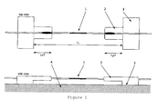
- a basic structure of the proposed passive athermal FBG (1) strain gauge is shown in Figure 1 - it consists of a structure comprising beams (2) and anchoring stands (3).
- Each beam (2) has a length L 2 / 2 and are made of a material with CTE ⁇ B not attached to the material (4) being monitored.
- the anchoring stands (3) are made of the same material as the beams (2) and are attached at a distance of L 1 to the material (4) being monitored.
- the fiber Bragg grating (1) is attached at its ends to the beams (2).
- Figure 2 presents another embodiment of the proposed design in which the anchoring stands (3) are connected through a frame (5) to form a suitable structure to define the distance L 1 between the anchoring stands (3) and that comprises flexures to minimize the load that is applied to the bonds between the anchoring stands (3) and the material (4) being monitored.
- the frame further provides suitable mechanical protection for the FBG (1) when no recoating of the pristine optical fiber is performed.
- the athermal strain gauge design compensates for both the FBG intrinsic temperature sensitivity and the CTE of the material being monitored. It is straightforward that the athermal design can be adjusted to compensate only for the FBG intrinsic temperature sensitivity.
- the athermal strain gauge is bonded to the material - e.g., composite material, concrete, steel, etc. - being monitored at the bottom surface of the anchoring stands. Under this condition, the strain gauge's "effective CTE" becomes equal to the one of the material being monitored, since the material deformation under temperature variations will be integrated by a geometrical change of the distance between the anchoring stands.
- L 1 and L 2 are the distance between the anchoring stands and the length of the beams, and ⁇ T and ⁇ ⁇ are defined as the temperature and strain sensitivities of the FBG, respectively.
- Minimum wavelength drift with temperature can be obtained by balancing the length of the beams to the distance between the anchoring stands, thus resulting in the following condition for the balancing ratio ( BR )
- BR L 2
- L 1 ⁇ T + ⁇ ⁇ ⁇ ⁇ M ⁇ T + ⁇ ⁇ ⁇ ⁇ B .
- aluminum presents several beneficial properties for manufacturing the athermal strain gauge - e.g., high Young modulus, high CTE ratio, out of the shelf availability in a broad dimensional range, easy material processing -, other materials can be employed - e.g., zinc, stainless steel, etc. -.
- Figure 3 shows the performance of the athermal FBG strain gauge compared to a standard FBG strain gauge for a temperature range compatible with most structural health monitoring applications. Data in Figure 3 also compares the strain shift of an unbonded bare FBG to the one of the standard FBG strain gauge bonded to a composite material. It is possible to observe that the standard FBG strain gauge presents additional strain shift induced by the CTE of the material. In this case, the athermal FBG strain gauge provides compensation for both the FBG thermal sensitivity and the CTE of the material.
Landscapes
- Physics & Mathematics (AREA)
- General Physics & Mathematics (AREA)
- Length Measuring Devices By Optical Means (AREA)
Abstract
Description
- The present invention relates to fiber Bragg gratings suitable for measuring strain, particularly those in which the cross-sensitivity to temperature is passively canceled without the use of an additional temperature reference.
- The present invention describes an athermal fiber Bragg grating strain gauge comprising a fiber Bragg grating (1) directly or indirectly attached at its ends to the material being monitored (4), wherein said fiber Bragg grating (1) is attached at least at one of its ends to a beam (2), and through that beam (2) to the material being monitored (4), where given the thermal behavior of the fiber Bragg grating strain gauge, the thermal expansion of the beam (2), the length of the beam (2) and the distance between attachments of the fiber Bragg grating (1) are set to partially compensate, fully compensate, or enhance the thermal sensitivity of the fiber Bragg grating (1).
- The present invention further describes an athermal fiber Bragg grating strain gauge characterized in that it comprises a fiber Bragg grating (1), said fiber Bragg grating (1) being attached at least at one of its ends to a beam (2), and through that beam (2) to an anchoring stand (3), said beam (2) being unattached to the material being monitored (4), said anchoring stand (3) being attached to the material being monitored (4), where the coefficient of thermal expansion of the beam (2), the length of the beam (2) and the distance between the anchoring stands (3) are set to partially compensate, fully compensate, or enhance the thermal sensitivity of the fiber Bragg grating (1).
- Anchoring stand is to be understood as any element comprising the function of coupling, no other direct or implied restriction is meant in this context as to its function, position or condition.
- A preferred embodiment of the present invention describes a fiber Bragg grating strain gauge comprising a fiber Bragg grating (1), beams (2) and anchoring stands (3), wherein that said fiber Bragg grating (1) is attached at both its ends to said beams (2), said beams (2) are not attached to the material being monitored (4), said anchoring stands (3) are attached to the material being monitored (4), wherein the length of the beams (2) and the distance between the anchoring stands (3) are set to partially compensate, fully compensate, or enhance the thermal sensitivity of the fiber Bragg grating (1).
- In another preferred embodiment of the present invention, both anchoring stands (3) are connected via a frame (5) that comprises flexures to form a flexible structure that minimizes strain induced load on the anchoring stands (3).
- In yet another preferred embodiment of the present invention, said frame (5) provides mechanical protection for the fiber Bragg grating (1).
- In yet another preferred embodiment of the present invention, the beams (2) have equal dimensions.
- In yet another preferred embodiment of the present invention, the beams (2) have different dimensions.
- In an even more preferred embodiment of the present invention, said total length of the beam or beams and said distance between the anchoring stands are set so:

where βT is the temperature sensitivity of the fiber Bragg grating (1), βε is the strain sensitivity of the fiber Bragg grating (1), ε(T) is the additional temperature strain induced by the beams (2), and ΔT is the temperature difference thus providing athermal operation. - In yet another preferred embodiment of the present invention, said total length of the beam or beams and said distance between the anchoring stands are set to additionally compensate the coefficient of thermal expansion of the material being monitored (4).
- In yet another but also preferred embodiment of the present invention, said total length of the beam or beams and said distance between the anchoring stands are set so the balancing ratio BR is given by:

where L1 is the distance between the anchoring stands (3), L2 is the length of the beams (2), βT is the temperature sensitivity of the fiber Bragg grating (1), βε is the strain sensitivity of the fiber Bragg grating (1), αM is the coefficient of thermal-expansion of the material being monitored (4), and αB is the coefficient of thermal-expansion of the beams (2) thus providing athermal operation of the strain gauge and compensating the CTE of the material being monitored (4). - In yet another preferred embodiment of the present invention, the beams (2) and the anchoring stands (3) consist of the same material.
- In yet another but also preferred embodiment of the present invention, both beams (2) and anchoring stands (3) consist of different materials.
- In yet another but still preferred embodiment of the present invention, said beams (2), anchoring stands (3) and frame (5) consist of the same material.
- In yet another preferred embodiment of the present invention, said beams (2), anchoring stands (3) and frame (5) consist of different materials.
- A FBG (Fiber Bragg Grating) is a periodic modulation of the refractive index of the core of a single mode optical fiber usually written by exposure to UV light. This periodic structure is characterized by a narrow reflective spectral response. The centre wavelength λ B of the reflection band matches the Bragg condition:


where α is the fiber coefficient of thermal-expansion (CTE) and ζ is the fiber thermo-optic coefficient, with values of 0.55 ppm/°C and 6.7 ppm/°C, respectively. - The wavelength shift induced by a longitudinal strain variation ε is given by:

where pe is the photoelastic coefficient of the fiber, with value 0.22. - In the last two equations, β T and βε are defined as the temperature and strain sensitivities of the FBG, respectively. The usual approximate values for these two coefficients on the C-band are β T = 7.25x10⁻⁶ °C-1 and βε = 0.76x10⁻⁶ µε-1.
- The overall Bragg wavelength shift induced by temperature change and/or strain is then given by:

- The proposed method for enabling strain measurements while canceling temperature sensitivity (TS) relies on subjecting the FBG to additional temperature induced strain, ε(T), according to the following expression:

- This method enables not only annulled temperature sensitivity - i.e., TS = 0 -, but also enhanced positive temperature sensitivity - i.e., TS > β T -, reduced positive temperature sensitivity - i.e., TS < β T -, or even negative temperature sensitivity - i.e., TS < 0 -. In the particular case of annulled temperature sensitivity, the exact balancing between the intrinsic FBG temperature sensitivity and temperature induced strain - β T = -βεε(T)/ΔT - provides so called athermal operation of the strain gauge.
- The most common method to overcome cross-sensitivity to temperature while measuring strain with FBGs relies on the use of an additional temperature reference - e.g., strain-inactive FBG [W. W. Morey, G. Meltz and J. M. Weiss, "Evaluation of a fiber Bragg grating hydrostatic pressure sensor," in Proceedings of the Eighth International Conference on Optical Fiber Sensors, Monterey, California, USA, Postdeadline Paper PD-4.4, 1992] -. Other methods, based on the use of dual wavelength FBG [M. G. Xu, J.-L. Archambault, L. Reekie and J. P. Dakin, "Discrimination between strain and temperature effects using dual/wavelength fiber grating sensors," Electronics Letters 30, pp. 1085-1087, 1994], FBG and fiber polarization-rocking filter [S. E. Kanellopoulos, V. A. Handerek and A. J. Rogers, "Simultaneous strain and temperature sensing with photo-generated in-fiber gratings," Optics Letters 20, pp. 333-335, 1995], non-sinusoidal FBG [G. P. Brady, K. Kalli, D. J. Webb, D. A. Jackson, L. Zhang and I. Bennion, "Recent developments in optical fiber sensing using fiber Bragg gratings," in Proceedings of the Fiber Optic and Laser Sensors XIV, Denver, Colorado, USA, SPIE 2839, pp. 8-19, 1994], FBG written in different diameter fiber [S. W. James, M. L. Dockney and R. P. Tatam, "Simultaneous independent temperature and strain measurement using in-fiber Bragg grating sensors," Electronics Letters 32, pp. 1133-1134, 1996], FBG and long period grating [H. Patrick, G. M. Williams, A. D. Kersey, J. R. Pedrazzani and A. M. Vengsarkar, "Hybrid fiber Bragg grating/long period fiber grating sensor for strain/temperature discrimination," Photonic Technology Letters 8, pp. 1223-1225, 1996], FBG and in-line fiber etalon [H. Singh and J. Sirkis, "Simultaneous measurement of strain and temperature using optical fiber sensors: two novel configuration" in Proceedings of the Eleventh International Conference on Optical Fiber Sensors, Hokkaido University, Sapporo, Japan, pp. 108-111, 1996], and FBG pair written in hi-bi PANDA fiber [L. A. Ferreira, F. M. Araújo, J. L. Santos and F. Farahi, "Simultaneous measurement of strain and temperature using interferometrically interrogated fiber Bragg grating sensors", Optical Engineering 39, pp. 2226-2234, 2000] have been demonstrated, but they are often too complex and difficult to implement in real world structures. Moreover, besides being not required in all the strain monitoring cases, the measurement of temperature by the referred methods implies the allocation of additional bandwidth to each sensor, therefore limiting the total number of sensors in a given sensing network. The proposed true passive athermal fiber Bragg grating strain gauge is thus of particular interest since it renders optional the measurement of temperature, benefiting large scale system design and performance. In addition, the proposed strain gauge can also be designed to further compensate for structural material thermal expansion, enabling load-induced strain-components to be discriminated from the thermal-induced strain-components.
- As mentioned, the method now proposed relies on subjecting the FBG to additional temperature induced strain. The simplest method of applying temperature dependent strain to a FBG is to attach it to a material with a CTE dissimilar to that of silica. However, this restricts the adjustment of the FBG sensitivity to the set of discrete values that can be obtained employing available materials. A well-known method of attaining a broad range of effective CTEs - including negative CTE values - is to provide a structure incorporating a proper arrangement of two materials with distinct CTEs [
DE3112193 ]. A proper design of such a structure can be used for packaging FBGs, allowing for continuous adjustment of the FBG temperature sensitivity. The particular case of athermal operation employing this concept has been the focus of several patent applications [WO 01/67142 A2 US 6393181 B1 ]. The implementation of athermal strain gauge packaging using two materials has also been the scope of several patent applications. Here, it is disclosed a FBG strain gauge construction that relies on a single material to attain athermal strain measurements in a considerable number of structural health monitoring applications. The disclosed design further allows the compensation for structural thermal expansion, thus enabling load-induced strain-components to be measured. - It is one of the intents of this invention to propose a design for an athermal strain gauge that enables strain measurements to be performed through a fiber Bragg grating sensor while canceling its intrinsic temperature sensitivity, thus extending the range of applications of such components. The disclosed design is based on a structure composed of a single material comprising beams and anchoring stands making an assembly that when bonded to a material being monitored allows the adjustment of the temperature sensitivity to zero, providing athermal operation of the strain gauge. The design can be made to match a particular material, involving the balancing of two lengths defined by the distance between the anchoring stands and the length of the beams. The disclosed design can be further adjusted to compensate for the thermal expansion of the material to which it is attached.
- It is obvious that the exact shape of said structure is not relevant to the effect. The shape of the sensor can be made flat, cylindrical or have any other shape that enables the use of the disclosed design in different monitoring applications, such as surface mountable through adhesive bonding or welding, embedding or grouting in concrete or embedding in composite materials.
- It is also possible to achieve the same effect by means of a single beam, in this case, the full length of the two beams being merged in one single structure.
-
-
Figure 1 - Design of the proposed passive athermal FBG strain gauge where (1) represents the fiber Bragg grating, (2) represents the beams with length L2, (3) represents the anchoring stands at a distance L1 and (4) represents the material being monitored. -
Figure 2 - Design of another embodiment of the proposed passive athermal FBG strain gauge where (1) represents the fiber Bragg grating, (2) represents the beams with length L2, (3) represents the anchoring stands, (4) represents the material being monitored and (5) represents the frame that mechanically connects the anchoring stands at a distance L1. -
Figure 3 - Athermal performance of the passive athermal FBG strain gauge compared to the temperature induced strain shift of a standard FBG strain gauge. -
Figure 4 - Comparison of a strain measurement performed with the disclosed passive athermal FBG strain gauge and with a standard FBG strain gauge. - As an example, a basic structure of the proposed passive athermal FBG (1) strain gauge is shown in
Figure 1 - it consists of a structure comprising beams (2) and anchoring stands (3). Each beam (2) has a length L2 /2 and are made of a material with CTE α B not attached to the material (4) being monitored. The anchoring stands (3) are made of the same material as the beams (2) and are attached at a distance of L1 to the material (4) being monitored. The fiber Bragg grating (1) is attached at its ends to the beams (2).Figure 2 presents another embodiment of the proposed design in which the anchoring stands (3) are connected through a frame (5) to form a suitable structure to define the distance L1 between the anchoring stands (3) and that comprises flexures to minimize the load that is applied to the bonds between the anchoring stands (3) and the material (4) being monitored. The frame further provides suitable mechanical protection for the FBG (1) when no recoating of the pristine optical fiber is performed. - Here it is provided an analysis of the temperature compensation performance of the athermal strain gauge design that compensates for both the FBG intrinsic temperature sensitivity and the CTE of the material being monitored. It is straightforward that the athermal design can be adjusted to compensate only for the FBG intrinsic temperature sensitivity. Consider that the athermal strain gauge is bonded to the material - e.g., composite material, concrete, steel, etc. - being monitored at the bottom surface of the anchoring stands. Under this condition, the strain gauge's "effective CTE" becomes equal to the one of the material being monitored, since the material deformation under temperature variations will be integrated by a geometrical change of the distance between the anchoring stands. In this case, and being α B the CTE of the beams and α M the CTE of the material being monitored, the following expression can be written for the FBG wavelength shift induced by temperature:

- In this expression, L 1 and L 2 are the distance between the anchoring stands and the length of the beams, and β T and βε are defined as the temperature and strain sensitivities of the FBG, respectively. The usual approximate values for these two coefficients on the C-band are β T = 7.25x10⁻⁶ °C-1 and βε = 0.76x10⁻⁶ µε-1, respectively. Minimum wavelength drift with temperature can be obtained by balancing the length of the beams to the distance between the anchoring stands, thus resulting in the following condition for the balancing ratio (BR)

- From this ratio, it is straightforward to state that minimum length design is obtained for maximum value of the CTE of the beams αB.It should also be emphasized that this design restricts the maximum FBG length to L1-L2 ; thus for a given FBG length, it is always possible to calculate the lengths L1 and L2 that fulfill both conditions. Taking into account these constrains, aluminum has been selected for building the strain gauge - α B = 23.5 ppm/°C -. Considering, as an example, strain measurements in a composite material with a typical CTE value of 2.5x10⁻⁶ °C-1 and the previous values given for β T and βε, equation 7 yields a ratio of 0.364, which for a distance between the anchoring stands of 40 mm results in a length of the beams of 14.6 mm. Although aluminum presents several beneficial properties for manufacturing the athermal strain gauge - e.g., high Young modulus, high CTE ratio, out of the shelf availability in a broad dimensional range, easy material processing -, other materials can be employed - e.g., zinc, stainless steel, etc. -.
-
Figure 3 shows the performance of the athermal FBG strain gauge compared to a standard FBG strain gauge for a temperature range compatible with most structural health monitoring applications. Data inFigure 3 also compares the strain shift of an unbonded bare FBG to the one of the standard FBG strain gauge bonded to a composite material. It is possible to observe that the standard FBG strain gauge presents additional strain shift induced by the CTE of the material. In this case, the athermal FBG strain gauge provides compensation for both the FBG thermal sensitivity and the CTE of the material. - Here it is provided an analysis of the strain measurement performance of the athermal strain gauge design that compensates for both the FBG intrinsic temperature sensitivity and the CTE of the material being monitored. For a strain εM applied to the material being monitored, the FBG will be subjected to a strain given by

- The Bragg wavelength shift associated with this strain is, therefore, given by

- The mentioned strain will arise only from load applied to the material being monitored, since any temperature induced deformation of the material will be effectively cancelled by the athermal design.
- Data in
Figure 4 demonstrate that once the gauge factor is set correctly, it is possible to provide very accurate strain measurements independent of temperature induced detrimental effects.
Claims (16)
- Athermal fiber Bragg grating strain gauge characterized in that it comprises a fiber Bragg grating (1) directly or indirectly attached at its ends to the material being monitored (4), wherein said fiber Bragg grating (1) is attached at least at one of its ends to a beam (2), and through that beam (2) to the material being monitored (4), where given the thermal behavior of the fiber Bragg grating strain gauge (1), the coefficient of thermal expansion of the beam (2), the length of the beam (2) and the distance between attachments of the fiber Bragg grating (1) are set to partially compensate, fully compensate, or enhance the thermal sensitivity of the fiber Bragg grating (1).
- Athermal fiber Bragg grating strain gauge according to the previous claim wherein it comprises a fiber Bragg grating (1), said fiber Bragg grating (1) being attached at least at one of its ends to a beam (2), and through that beam (2) to an anchoring stand (3), said beam (2) being unattached to the material being monitored (4), said anchoring stand (3) being attached to the material being monitored (4), where the coefficient of thermal expansion of the beam (2), the length of the beam (2) and the distance between the anchoring stands (3) of the fiber Bragg grating (1) are set to partially compensate, fully compensate, or enhance the thermal sensitivity of the fiber Bragg grating (1).
- Athermal fiber Bragg grating strain gauge according to the previous claim wherein it comprises a fiber Bragg grating (1), beams (2) and anchoring stands (3), where that said fiber Bragg grating (1) is attached at both its ends to said beams (2), said beams (2) are not attached to the material being monitored (4), said anchoring stands (3) are attached to the material being monitored (4), wherein the coefficient of thermal expansion of the beams (2), the length of the beams (2) and the distance between the anchoring stands (3) are set to partially compensate, fully compensate, or enhance the thermal sensitivity of the fiber Bragg grating (1).
- Athermal fiber Bragg grating strain gauge according to the previous claim, wherein both anchoring stands (3) are connected via a frame (5) that comprises flexures to form a flexible structure that minimizes strain induced load on the anchoring stands (3).
- Athermal fiber Bragg grating strain gauge according to the previous claim wherein said frame (5) provides mechanical protection for the fiber Bragg grating (1).
- Athermal fiber Bragg grating strain gauge according to any one of the claims 3 to 5 wherein the beams (2) have equal dimensions.
- Athermal fiber Bragg grating strain gauge according to any one of the claims 3 to 5 wherein the beams (2) have different dimensions.
- Athermal fiber Bragg grating strain gauge according to any one of the previous claims wherein said total length of the beam or beams (2) and said distance between the anchoring stands (3) are set so:

- Athermal fiber Bragg grating strain gauge according to any one of the previous claims wherein said coefficient of thermal expansion of the beam or beams, the total length of the beam or beams (2) and said distance between the anchoring stands (3) are set to additionally compensate the coefficient of thermal expansion of the material being monitored (4).
- Athermal fiber Bragg grating strain gauge according to the previous claim wherein said total length of the beam or beams (2) and said distance between the anchoring stands (3) are set so the balancing ratio BR is given by:

where L1 is the distance between the anchoring stands (3), L2 is the total length of the beam or beams (2), βT is the temperature sensitivity of the fiber Bragg grating (1), βε is the strain sensitivity of the fiber Bragg grating (1), αM is the coefficient of thermal-expansion of the material being monitored (4), and αB is the coefficient of thermal-expansion of the beam or beams (2) thus providing athermal operation of the strain gauge and compensating the CTE of the material being monitored. - Athermal fiber Bragg grating strain gauge according to any one of the claims 1 to 10, wherein beams (2) consist of the same material.
- Athermal fiber Bragg grating strain gauge according to any one of the claims 1 to 10, wherein beams (2) consist of different materials.
- Athermal fiber Bragg grating strain gauge according to any one of the claims 1 to 10 wherein the beams (2) and the anchoring stands (3) consist of the same material.
- Athermal fiber Bragg grating strain gauge according to any one of the claims 1 to 10, wherein beams (2) and anchoring stands (3) consist of different materials.
- Athermal fiber Bragg grating strain gauge according to any one of the claims 4 to 10, wherein said beams (2), anchoring stands (3) and frame (5) consist of the same material.
- Athermal fiber Bragg grating strain gauge according to any one of the claims 4 to 10, wherein said beams (2), anchoring stands (3) and frame (5) consist of different materials.
Priority Applications (1)
| Application Number | Priority Date | Filing Date | Title |
|---|---|---|---|
| EP09398004A EP2295946A1 (en) | 2009-09-11 | 2009-09-11 | Athermal fiber bragg grating strain gauge |
Applications Claiming Priority (1)
| Application Number | Priority Date | Filing Date | Title |
|---|---|---|---|
| EP09398004A EP2295946A1 (en) | 2009-09-11 | 2009-09-11 | Athermal fiber bragg grating strain gauge |
Publications (1)
| Publication Number | Publication Date |
|---|---|
| EP2295946A1 true EP2295946A1 (en) | 2011-03-16 |
Family
ID=41478825
Family Applications (1)
| Application Number | Title | Priority Date | Filing Date |
|---|---|---|---|
| EP09398004A Withdrawn EP2295946A1 (en) | 2009-09-11 | 2009-09-11 | Athermal fiber bragg grating strain gauge |
Country Status (1)
| Country | Link |
|---|---|
| EP (1) | EP2295946A1 (en) |
Cited By (16)
| Publication number | Priority date | Publication date | Assignee | Title |
|---|---|---|---|---|
| CN103115694A (en) * | 2013-01-17 | 2013-05-22 | 中国地震局地壳应力研究所 | Fiber Bragg grating (FBG) high-sensitivity temperature sensor based on low-melting-point glass welding |
| CN103822738A (en) * | 2014-01-03 | 2014-05-28 | 重庆大学 | Stress sensor based on fiber gratings |
| ITBO20130135A1 (en) * | 2013-03-28 | 2014-09-29 | Filippo Bastianini | DEFORMATION SENSOR WITH BRAGG FIBER OPTICAL RETICLE, THERMOCOMPENSED, IMPACT RESISTANCE, WITH ADJUSTABLE SENSITIVITY AND ADJUSTABLE FLANGES |
| CN105806248A (en) * | 2016-05-30 | 2016-07-27 | 中国船舶重工集团公司第七0四研究所 | Marine fiber grating strain sensor |
| WO2017050767A1 (en) * | 2015-09-21 | 2017-03-30 | fos4X GmbH | Light guide clamping device, fibre optic sensor and production method |
| CN108139236A (en) * | 2015-09-21 | 2018-06-08 | 福斯4X股份有限公司 | Sensor patch and its method for manufacturing sensor patch |
| CN108226216A (en) * | 2016-12-22 | 2018-06-29 | 株式会社三丰 | Linear expansion coefficient determining method and measurement device |
| CN108680115A (en) * | 2018-07-25 | 2018-10-19 | 深圳市简测科技有限公司 | A kind of device for monitoring the deformation of piping lane bidirectional displacement |
| CN109682515A (en) * | 2019-02-20 | 2019-04-26 | 天津师范大学 | Optical fiber optical grating stress sensor and application for the measurement of hull local strength |
| CN110057480A (en) * | 2019-05-21 | 2019-07-26 | 衢州学院 | A kind of the fiber grating torque sensor and its installation method of forked type conjugated structure |
| CN110530282A (en) * | 2019-09-04 | 2019-12-03 | 苏州热工研究院有限公司 | Three spindle-type fiber grating strain measurement sensors of adjustable sensitivity |
| CN110645905A (en) * | 2019-11-11 | 2020-01-03 | 武汉理工大学 | Fiber grating strain sensor with adjustable sensitivity and use method thereof |
| DE102018123654A1 (en) * | 2018-09-25 | 2020-03-26 | Fugro Technology B.V. | Bridge-based WIM system |
| CN114485452A (en) * | 2022-02-17 | 2022-05-13 | 杭州光潋科技有限公司 | Non-thermal optical fiber strain gauge |
| WO2022197185A1 (en) * | 2021-03-19 | 2022-09-22 | Somni Corporation B.V. | Fibre-optic sensor for measuring a physical quantity |
| CN117889898A (en) * | 2024-03-18 | 2024-04-16 | 中国地震局地球物理研究所 | Fiber bragg grating sensor for strain and temperature double-parameter measurement |
Citations (8)
| Publication number | Priority date | Publication date | Assignee | Title |
|---|---|---|---|---|
| DE3112193A1 (en) | 1981-03-06 | 1982-10-14 | Paul 7032 Sindelfingen Merkle | Electromagnetic pendulum (clock pendulum) |
| WO2001020377A1 (en) * | 1999-09-10 | 2001-03-22 | Siemens Aktiengesellschaft | Method for producing an optical grating on an optical conductor and device comprising a grating of this type |
| WO2001067142A2 (en) | 2000-03-06 | 2001-09-13 | Cidra Corporation | TEMPERATURE COMPENSATED BRAGG GRATING AND ASSOCIATED OPTICAL DEVICEs |
| US6393181B1 (en) | 1997-06-19 | 2002-05-21 | Jds Uniphase Pty. Ltd. | Temperature stable Bragg grating package with post tuning for accurate setting of centre frequency |
| JP2002286563A (en) * | 2001-03-28 | 2002-10-03 | Kyowa Electron Instr Co Ltd | Optical fiber type strain gage |
| JP2003254723A (en) * | 2002-03-01 | 2003-09-10 | Tokyo Electric Power Services Co Ltd | Measuring instrument for measuring distortion quantity of structure |
| EP1679497A1 (en) * | 2005-01-10 | 2006-07-12 | Fibersensing - Sistemas Avançados de Monitorização S.A. | Passive athermal fibre Bragg grating strain gage |
| WO2009128040A1 (en) | 2008-04-18 | 2009-10-22 | Institute Of Crustal Dynamics, China Earthquake Administration | A high sensitive fiber bragg grating strain sensor with automatic temperature compensation |
-
2009
- 2009-09-11 EP EP09398004A patent/EP2295946A1/en not_active Withdrawn
Patent Citations (8)
| Publication number | Priority date | Publication date | Assignee | Title |
|---|---|---|---|---|
| DE3112193A1 (en) | 1981-03-06 | 1982-10-14 | Paul 7032 Sindelfingen Merkle | Electromagnetic pendulum (clock pendulum) |
| US6393181B1 (en) | 1997-06-19 | 2002-05-21 | Jds Uniphase Pty. Ltd. | Temperature stable Bragg grating package with post tuning for accurate setting of centre frequency |
| WO2001020377A1 (en) * | 1999-09-10 | 2001-03-22 | Siemens Aktiengesellschaft | Method for producing an optical grating on an optical conductor and device comprising a grating of this type |
| WO2001067142A2 (en) | 2000-03-06 | 2001-09-13 | Cidra Corporation | TEMPERATURE COMPENSATED BRAGG GRATING AND ASSOCIATED OPTICAL DEVICEs |
| JP2002286563A (en) * | 2001-03-28 | 2002-10-03 | Kyowa Electron Instr Co Ltd | Optical fiber type strain gage |
| JP2003254723A (en) * | 2002-03-01 | 2003-09-10 | Tokyo Electric Power Services Co Ltd | Measuring instrument for measuring distortion quantity of structure |
| EP1679497A1 (en) * | 2005-01-10 | 2006-07-12 | Fibersensing - Sistemas Avançados de Monitorização S.A. | Passive athermal fibre Bragg grating strain gage |
| WO2009128040A1 (en) | 2008-04-18 | 2009-10-22 | Institute Of Crustal Dynamics, China Earthquake Administration | A high sensitive fiber bragg grating strain sensor with automatic temperature compensation |
Non-Patent Citations (9)
| Title |
|---|
| G. P. BRADY ET AL.: "Recent developments in optical fiber sensing using fiber Bragg gratings", PROCEEDINGS OF THE FIBER OPTIC AND LASER SENSORS XIV, 1994, pages 8 - 19 |
| H. PATRICK ET AL.: "Hybrid fiber Bragg grating/long period fiber grating sensor for strain/temperature discrimination", PHOTONIC TECHNOLOGY LETTERS, vol. 8, 1996, pages 1223 - 1225 |
| H. SINGH; J. SIRKIS: "Simultaneous measurement of strain and temperature using optical fiber sensors: two novel configuration", PROCEEDINGS OF THE ELEVENTH INTERNATIONAL CONFERENCE ON OPTICAL FIBER SENSORS, 1996, pages 108 - 111 |
| L. A. FERREIRA ET AL.: "Simultaneous measurement of strain and temperature using interferometrically interrogated fiber Bragg grating sensors", OPTICAL ENGINEERING, vol. 39, 2000, pages 2226 - 2234 |
| LI KUO; ZHOU ZHEN'AN: "A high Sensitive fiber Bragg grating strain sensor with automatic temperature compensation", CHINESE OPTICS LETTERS, vol. 7, no. 3, 2009, pages 191 - 193, XP003030828 |
| M. G. XU ET AL.: "Discrimination between strain and temperature effects using dual/wavelength fiber grating sensors", ELECTRONICS LETTERS, vol. 30, 1994, pages 1085 - 1087 |
| S. E. KANELLOPOULOS; V. A. HANDEREK; A. J. ROGERS: "Simultaneous strain and temperature sensing with photo-generated in-fiber gratings", OPTICS LETTERS, vol. 20, 1995, pages 333 - 335 |
| S. W. JAMES; M. L. DOCKNEY; R. P. TATAM: "Simultaneous independent temperature and strain measurement using in-fiber Bragg grating sensors", ELECTRONICS LETTERS, vol. 32, 1996, pages 1133 - 1134 |
| W. W. MOREY; G. MELTZ; J. M. WEISS: "Evaluation of a fiber Bragg grating hydrostatic pressure sensor", PROCEEDINGS OF THE EIGHTH INTERNATIONAL CONFERENCE ON OPTICAL FIBER SENSORS, 1992 |
Cited By (28)
| Publication number | Priority date | Publication date | Assignee | Title |
|---|---|---|---|---|
| CN103115694B (en) * | 2013-01-17 | 2015-02-04 | 中国地震局地壳应力研究所 | Fiber Bragg grating (FBG) high-sensitivity temperature sensor based on low-melting-point glass welding |
| CN103115694A (en) * | 2013-01-17 | 2013-05-22 | 中国地震局地壳应力研究所 | Fiber Bragg grating (FBG) high-sensitivity temperature sensor based on low-melting-point glass welding |
| ITBO20130135A1 (en) * | 2013-03-28 | 2014-09-29 | Filippo Bastianini | DEFORMATION SENSOR WITH BRAGG FIBER OPTICAL RETICLE, THERMOCOMPENSED, IMPACT RESISTANCE, WITH ADJUSTABLE SENSITIVITY AND ADJUSTABLE FLANGES |
| CN103822738A (en) * | 2014-01-03 | 2014-05-28 | 重庆大学 | Stress sensor based on fiber gratings |
| US10761261B2 (en) | 2015-09-21 | 2020-09-01 | fos4X GmbH | Light guide clamping device, fiber optic sensor and production method |
| US10684145B2 (en) | 2015-09-21 | 2020-06-16 | fos4X GmbH | Sensor patch and method for producing a sensor patch |
| WO2017050767A1 (en) * | 2015-09-21 | 2017-03-30 | fos4X GmbH | Light guide clamping device, fibre optic sensor and production method |
| CN108139237A (en) * | 2015-09-21 | 2018-06-08 | 福斯4X股份有限公司 | Light guide clamping device, fibre optical sensor and its manufacturing method |
| CN108139236A (en) * | 2015-09-21 | 2018-06-08 | 福斯4X股份有限公司 | Sensor patch and its method for manufacturing sensor patch |
| CN105806248B (en) * | 2016-05-30 | 2017-08-25 | 中国船舶重工集团公司第七0四研究所 | Fiber Bragg grating strain sensor peculiar to vessel |
| CN105806248A (en) * | 2016-05-30 | 2016-07-27 | 中国船舶重工集团公司第七0四研究所 | Marine fiber grating strain sensor |
| CN108226216B (en) * | 2016-12-22 | 2021-11-16 | 株式会社三丰 | Method and apparatus for measuring linear expansion coefficient |
| CN108226216A (en) * | 2016-12-22 | 2018-06-29 | 株式会社三丰 | Linear expansion coefficient determining method and measurement device |
| CN108680115A (en) * | 2018-07-25 | 2018-10-19 | 深圳市简测科技有限公司 | A kind of device for monitoring the deformation of piping lane bidirectional displacement |
| DE102018123654A1 (en) * | 2018-09-25 | 2020-03-26 | Fugro Technology B.V. | Bridge-based WIM system |
| CN109682515A (en) * | 2019-02-20 | 2019-04-26 | 天津师范大学 | Optical fiber optical grating stress sensor and application for the measurement of hull local strength |
| CN110057480A (en) * | 2019-05-21 | 2019-07-26 | 衢州学院 | A kind of the fiber grating torque sensor and its installation method of forked type conjugated structure |
| CN110057480B (en) * | 2019-05-21 | 2024-02-06 | 衢州学院 | Fiber bragg grating torque sensor with fork-shaped conjugated structure and installation method thereof |
| CN110530282A (en) * | 2019-09-04 | 2019-12-03 | 苏州热工研究院有限公司 | Three spindle-type fiber grating strain measurement sensors of adjustable sensitivity |
| CN110530282B (en) * | 2019-09-04 | 2022-04-01 | 苏州热工研究院有限公司 | Three-axis fiber grating strain measurement sensor with adjustable sensitivity |
| CN110645905A (en) * | 2019-11-11 | 2020-01-03 | 武汉理工大学 | Fiber grating strain sensor with adjustable sensitivity and use method thereof |
| CN110645905B (en) * | 2019-11-11 | 2021-08-10 | 武汉理工大学 | Fiber grating strain sensor with adjustable sensitivity and use method thereof |
| WO2022197185A1 (en) * | 2021-03-19 | 2022-09-22 | Somni Corporation B.V. | Fibre-optic sensor for measuring a physical quantity |
| NL2027778B1 (en) * | 2021-03-19 | 2022-09-29 | Somni Corp B V | Fibre-optic sensor for measuring a physical quantity |
| CN114485452A (en) * | 2022-02-17 | 2022-05-13 | 杭州光潋科技有限公司 | Non-thermal optical fiber strain gauge |
| CN114485452B (en) * | 2022-02-17 | 2024-05-17 | 杭州光潋科技有限公司 | Athermal optical fiber strain gauge |
| CN117889898A (en) * | 2024-03-18 | 2024-04-16 | 中国地震局地球物理研究所 | Fiber bragg grating sensor for strain and temperature double-parameter measurement |
| CN117889898B (en) * | 2024-03-18 | 2024-05-28 | 中国地震局地球物理研究所 | Fiber bragg grating sensor for strain and temperature double-parameter measurement |
Similar Documents
| Publication | Publication Date | Title |
|---|---|---|
| EP2295946A1 (en) | Athermal fiber bragg grating strain gauge | |
| US7068869B1 (en) | Passive athermal fiber bragg grating strain gage | |
| Fernández-Valdivielso et al. | Simultaneous measurement of strain and temperature using a fiber Bragg grating and a thermochromic material | |
| Zhang et al. | FBG-type sensor for simultaneous measurement of force (or displacement) and temperature based on bilateral cantilever beam | |
| Xu et al. | Thermally-compensated bending gauge using surface-mounted fibre gratings | |
| Davis et al. | Shape and vibration mode sensing using a fiber optic Bragg grating array | |
| US9267854B2 (en) | Strain and temperature discrimination using fiber bragg gratings in a cross-wire configuration | |
| US10620018B2 (en) | Method for measuring the displacement profile of buildings and sensor therefor | |
| Di Sante et al. | Temperature-compensated fibre Bragg grating‐based sensor with variable sensitivity | |
| KR101203700B1 (en) | Fiber bragg grating sensor and system of measuring temperature and strain using the same | |
| CN104198083A (en) | Fiber grating temperature sensor | |
| EP3983268B1 (en) | Method and system for detecting and measuring a braking force of a braking system for vehicle, by means of photonic sensors incorporated in a brake pad | |
| EP1372006A1 (en) | Optical waveguide grating device and sensors utilising the device | |
| US6833541B2 (en) | Dual-parameter optical waveguide grating sensing device and sensor | |
| CN106524937A (en) | Fiber bragg grating strain device | |
| EP3983774A1 (en) | Method and system for detecting and measuring a braking force of a braking system for vehicle, by means of photonic sensors incorporated in a brake caliper | |
| CN206192288U (en) | Fiber grating effector | |
| Pieterse | An experimental four-component optical fibre balance | |
| CN100494975C (en) | Metal corrosion monitoring fiber grating sensing device | |
| Maul et al. | Sensing of surface strain with flexible fiber Bragg strain gages | |
| Zhu et al. | Fiber Bragg grating accelerometer with temperature insensitivity | |
| Hao et al. | Packaging effects on fiber bragg grating sensor performance | |
| Liu et al. | Long-period fiber grating curvature sensor based on temperature-insensitive wavelength separation measurements | |
| Xu et al. | Structural bending sensor using fiber gratings | |
| Viegas et al. | Non-terminal miniature fiber Bragg grating temperature probe based in a u-shape lossless taper |
Legal Events
| Date | Code | Title | Description |
|---|---|---|---|
| PUAI | Public reference made under article 153(3) epc to a published international application that has entered the european phase |
Free format text: ORIGINAL CODE: 0009012 |
|
| AK | Designated contracting states |
Kind code of ref document: A1 Designated state(s): AT BE BG CH CY CZ DE DK EE ES FI FR GB GR HR HU IE IS IT LI LT LU LV MC MK MT NL NO PL PT RO SE SI SK SM TR |
|
| AX | Request for extension of the european patent |
Extension state: AL BA RS |
|
| 17P | Request for examination filed |
Effective date: 20110916 |
|
| 17Q | First examination report despatched |
Effective date: 20111013 |
|
| TPAC | Observations filed by third parties |
Free format text: ORIGINAL CODE: EPIDOSNTIPA |
|
| STAA | Information on the status of an ep patent application or granted ep patent |
Free format text: STATUS: THE APPLICATION IS DEEMED TO BE WITHDRAWN |
|
| 18D | Application deemed to be withdrawn |
Effective date: 20130308 |