EP2295913A2 - Spiral pipe heat excahnger with tilted pipe sections - Google Patents
Spiral pipe heat excahnger with tilted pipe sections Download PDFInfo
- Publication number
- EP2295913A2 EP2295913A2 EP10173013A EP10173013A EP2295913A2 EP 2295913 A2 EP2295913 A2 EP 2295913A2 EP 10173013 A EP10173013 A EP 10173013A EP 10173013 A EP10173013 A EP 10173013A EP 2295913 A2 EP2295913 A2 EP 2295913A2
- Authority
- EP
- European Patent Office
- Prior art keywords
- heat
- pipe
- transfer pipe
- transfer
- upstream
- Prior art date
- Legal status (The legal status is an assumption and is not a legal conclusion. Google has not performed a legal analysis and makes no representation as to the accuracy of the status listed.)
- Granted
Links
- 238000011144 upstream manufacturing Methods 0.000 claims abstract description 80
- 239000012530 fluid Substances 0.000 claims abstract description 53
- 238000010586 diagram Methods 0.000 description 3
- 125000006850 spacer group Chemical group 0.000 description 2
- 230000000694 effects Effects 0.000 description 1
- 238000012423 maintenance Methods 0.000 description 1
Images


Classifications
-
- F—MECHANICAL ENGINEERING; LIGHTING; HEATING; WEAPONS; BLASTING
- F28—HEAT EXCHANGE IN GENERAL
- F28F—DETAILS OF HEAT-EXCHANGE AND HEAT-TRANSFER APPARATUS, OF GENERAL APPLICATION
- F28F9/00—Casings; Header boxes; Auxiliary supports for elements; Auxiliary members within casings
- F28F9/007—Auxiliary supports for elements
- F28F9/013—Auxiliary supports for elements for tubes or tube-assemblies
-
- F—MECHANICAL ENGINEERING; LIGHTING; HEATING; WEAPONS; BLASTING
- F28—HEAT EXCHANGE IN GENERAL
- F28D—HEAT-EXCHANGE APPARATUS, NOT PROVIDED FOR IN ANOTHER SUBCLASS, IN WHICH THE HEAT-EXCHANGE MEDIA DO NOT COME INTO DIRECT CONTACT
- F28D7/00—Heat-exchange apparatus having stationary tubular conduit assemblies for both heat-exchange media, the media being in contact with different sides of a conduit wall
- F28D7/02—Heat-exchange apparatus having stationary tubular conduit assemblies for both heat-exchange media, the media being in contact with different sides of a conduit wall the conduits being helically coiled
-
- F—MECHANICAL ENGINEERING; LIGHTING; HEATING; WEAPONS; BLASTING
- F28—HEAT EXCHANGE IN GENERAL
- F28D—HEAT-EXCHANGE APPARATUS, NOT PROVIDED FOR IN ANOTHER SUBCLASS, IN WHICH THE HEAT-EXCHANGE MEDIA DO NOT COME INTO DIRECT CONTACT
- F28D7/00—Heat-exchange apparatus having stationary tubular conduit assemblies for both heat-exchange media, the media being in contact with different sides of a conduit wall
- F28D7/16—Heat-exchange apparatus having stationary tubular conduit assemblies for both heat-exchange media, the media being in contact with different sides of a conduit wall the conduits being arranged in parallel spaced relation
- F28D7/1615—Heat-exchange apparatus having stationary tubular conduit assemblies for both heat-exchange media, the media being in contact with different sides of a conduit wall the conduits being arranged in parallel spaced relation the conduits being inside a casing and extending at an angle to the longitudinal axis of the casing; the conduits crossing the conduit for the other heat exchange medium
- F28D7/1623—Heat-exchange apparatus having stationary tubular conduit assemblies for both heat-exchange media, the media being in contact with different sides of a conduit wall the conduits being arranged in parallel spaced relation the conduits being inside a casing and extending at an angle to the longitudinal axis of the casing; the conduits crossing the conduit for the other heat exchange medium with particular pattern of flow of the heat exchange media, e.g. change of flow direction
-
- F—MECHANICAL ENGINEERING; LIGHTING; HEATING; WEAPONS; BLASTING
- F28—HEAT EXCHANGE IN GENERAL
- F28F—DETAILS OF HEAT-EXCHANGE AND HEAT-TRANSFER APPARATUS, OF GENERAL APPLICATION
- F28F17/00—Removing ice or water from heat-exchange apparatus
- F28F17/005—Means for draining condensates from heat exchangers, e.g. from evaporators
-
- F—MECHANICAL ENGINEERING; LIGHTING; HEATING; WEAPONS; BLASTING
- F28—HEAT EXCHANGE IN GENERAL
- F28F—DETAILS OF HEAT-EXCHANGE AND HEAT-TRANSFER APPARATUS, OF GENERAL APPLICATION
- F28F2240/00—Spacing means
Definitions
- the present invention relates to a heat exchanger that exchanges heat between external fluid introduced from outside and a heat-transfer member for heat exchange.
- heat-transfer pipes are disposed so as to cross a flow path of an external fluid on an upstream side and a downstream side, respectively, of the flow path.
- heat-transfer pipes are arranged so as to horizontally cross an upstream side and a downstream side, respectively, of the flow path of an external fluid. Accordingly, drain attached to the heat-transfer pipes as a result of heat exchange is likely to remain, which may hinder heat exchange and thus disable maintenance of efficiency of heat exchange.
- a heat exchanger includes a heat-transfer pipe for heat exchange and is configured such that heat exchange is performed between an external fluid flowing outside the heat-transfer pipe and the heat-transfer pipe.
- the heat exchanger may include a housing space for housing the heat-transfer pipe.
- the heat exchanger may be configured such that the external fluid introduced from outside is discharged after flowing through the housing space in which the heat-transfer pipe for heat exchange is housed, to thereby perform heat exchange between the external fluid and an internal fluid flowing inside the heat-transfer pipe.
- the heat exchanger may include a spiral heat-transfer pipe having a spiral shape as the heat-transfer pipe.
- This spiral shape can also be described as helical shape.
- the spiral heat-transfer pipe may include an upstream heat-transfer pipe section disposed on an upstream side of a flow path of the external fluid in a direction crossing the flow path; and a downstream heat-transfer pipe section disposed on a downstream side of the flow path in a direction crossing the flow path.
- each of an axis of the upstream heat-transfer pipe section and an axis of the downstream heat-transfer pipe section in the spiral heat-transfer pipe may be tilted with respect to a horizontal plane, and one of the axes may be relatively tilted with respect to the other of the axes, so that the axis of the upstream heat-transfer pipe section crosses the axis of the downstream heat-transfer pipe section.
- cross here may be interpreted to mean that, when the spiral heat-transfer pipe is projected from the upstream side toward the downstream side of the flow path of the external fluid, the axis of the upstream heat-transfer pipe section and the axis of the downstream heat-transfer pipe section cross each other in a projected plan view.
- the heat exchanger configured to have the tilted spiral heat-transfer pipe as above, since each of the upstream heat-transfer pipe section and the downstream heat-transfer pipe section, each crossing the flow path of the external fluid, is tilted with respect to the horizontal plane, drain, even if attached to the heat-transfer pipe as a result of heat exchange, can be made to flow along the tilt toward side areas of the flow path, and thus is unlikely to remain. Accordingly, heat exchange is unlikely to be hindered by remaining drain attached to each of the upstream heat-transfer pipe section and the downstream heat-transfer pipe section. Thus, an improved efficiency of heat exchange can be achieved.
- the upstream heat-transfer pipe section and the downstream heat-transfer pipe section are disposed in a positional relationship such that the axis of the upstream heat-transfer pipe section and the axis of the downstream heat-transfer pipe section cross each other in the projected plan view when the spiral heat-transfer pipe is projected from the upstream side toward the downstream side of the flow path.
- This configuration can reduce areas through which the external fluid simply passes, as compared with a non-tilted configuration (for example, a configuration in which the axis of the upstream heat-transfer pipe section and the axis of the downstream heat-transfer pipe section are parallel and overlapped in the projected plan view).
- a non-tilted configuration for example, a configuration in which the axis of the upstream heat-transfer pipe section and the axis of the downstream heat-transfer pipe section are parallel and overlapped in the projected plan view.
- a plurality of the spiral heat-transfer pipes may be housed in the housing space so as to form multiple spirals.
- the plurality of the spiral heat-transfer pipes may be stacked in a direction crossing a flowing direction of the external fluid (specifically, a direction crossing a surface defined by a longitudinal direction of the spiral heat-transfer pipes and the flowing direction, for example a vertical direction) to form multiple spirals.
- each of the plurality of the spiral heat-transfer pipes may be relatively shifted with respect to the other spiral heat-transfer pipes in a predetermined direction.
- the predetermined direction may be a direction crossing a neighboring direction of the spiral heat-transfer pipes or the flowing direction of the external fluid.
- At least two most neighboring spiral heat-transfer pipes may be configured as follows: one of the two spiral heat-transfer pipes is located upstream from the other in the flowing direction of the external fluid, and thereby the two spiral heat-transfer pipes are shifted with respect to each other.
- the two spiral heat-transfer pipes may be stacked in the vertical direction (in other words, the two spiral heat-transfer pipes may be relatively shifted with respect to each other in the vertical direction).
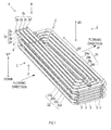
- a heat exchanger 1 houses a heat-transfer pipe group 2 in a housing space (a space inside a housing 10) 11.
- the heat exchanger 1 is configured such that an external fluid introduced from outside flows through the housing space 11 and is discharged from the housing space 11, to thereby perform heat exchange between the external fluid and an internal fluid flowing inside pipes 2a-2h.
- the heat-transfer pipe group 2 includes a first pipe set 2x and a second pipe set 2y, as shown in FIG. 1 .
- the first pipe set 2x includes pipes 2a, 2b, 2c, and 2b
- the second pipe set 2y includes pipes 2e, 2f, 2g and 2h.
- Each of the pipes 2a-2h is formed to have a spiral shape. This spiral shape can also be described as helical shape. Each of the pipes 2a-2h has each different outside diameter of the spiral shape. In other words, sizes of areas spirally surrounded by the respective pipes 2a-2h are different.
- the first pipe set 2x and the second pipe set 2y are stacked along a stacking direction d3, while relatively shifted slightly with respect to each other in a flowing direction d1 of the external fluid (see FIGS. 3A-3D ).
- the stacking direction d3 is interpreted as a direction perpendicular to an alignment direction of the pipes 2a-2d, or an alignment direction 2e ⁇ 2h (the same as the flowing direction d1 of the external fluid) (see FIG. 1 ).
- the pipe 2a is located upstream from the pipe 2e in the flowing direction d1 of the external fluid, and thereby the pipe 2a and the pipe 2e are relatively shifted with respect to each other in the flowing direction d1 of the external fluid (see FIGS. 3A-3D ).
- the pipe 2a and the pipe 2e are also relatively shifted with respect to each other in the stacking direction d3 (the vertical direction). That is, the pipe 2a and the pipe 2e are stacked in the stacking direction d3 (the vertical direction) and also are relatively shifted with respect to each other in the flowing direction d1.
- spacers 3 are disposed in the heat-transfer pipe group 2 at both longitudinal end sides of the heat-transfer pipe group 2. Specifically, the spacers 3 are disposed between the first pipe set 2x and the second pipe set 2y at the both longitudinal end sides of the heat-transfer group 2.
- the pipes 2a-2h includes sections disposed in a direction crossing a flow path of the external fluid on each of an upstream side and a downstream side of the flow path.
- a specific explanation is provided here regarding the first pipe set 2x.
- the second pipe set 2y i.e., the pipes 2e-2h), of which a detailed explanation is omitted, has the same structure as the first pipe set 2x.
- the pipe 2a has a section on the upstream side (hereinafter referred to as the "upstream pipe") 22a and a section on the downstream side (hereinafter referred to as the "downstream pipe") 24a.
- the pipe 2b has an upstream pipe 22b and a downstream pipe 24b
- the pipe 2c has an upstream pipe 22c and a downstream pipe 24c
- the pipe 2d has an upstream pipe 22d and a downstream pipe 24d.
- the upstream pipes 22a-22d and upstream pipes (not specifically shown) of the pipes 2e-2h are also collectively referred to as the "upstream pipe 22”.
- the downstream pipes 24a-24d and downstream pipes (not specifically shown) of the pipes 2e-2h are also collectively referred to as the "downstream pipe 24".
- the external fluid flows crossing over the upstream pipe 22 of the pipes 2a-2h, and then flows crossing over the downstream pipe 24 of the pipes 2a-2h.
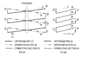
- each of the upstream pipe 22 and the downstream pipe 24 is tilted with respect to a horizontal plane, as shown in FIG. 2 .
- the upstream pipe 22 and the downstream pipe 24 are arranged in a positional relationship such that an axis 12 of the upstream pipe 22 crosses an axis 14 of the downstream pipe 24 in a projected plan view when the housing space 11 is projected from the upstream side toward the downstream side of the flow path.
- one of the axis 12 of the upstream pipe 22 and the axis 14 of the downstream pipe 24 is relatively tilted with respect to the other, and thereby the axis 12 of the upstream pipe 22 crosses the axis 14 of the downstream pipe 24.
- the upstream pipe 22 and the downstream pipe 24 are configured to have a same length and a same tilting angle.
- “Have the same tilting angle” here means that interior angles with respect to a horizontal plane are the same. More specifically, an interior angle ⁇ formed by the horizontal plane and the upstream pipe 22 and an interior angle ⁇ formed by the horizontal plane and the downstream pipe 24 are the same.
- the axis 12 of the upstream pipe 22 and the axis 14 of the downstream pipe 24 cross each another in a position ⁇ in a longitudinal direction d2 of the pipes 2a-2h obtained by equally dividing a length of each of the pipes 2a-2h by the number of the stacked pipe sets.
- the downstream pipe 24 may have a tilting angle larger than the upstream pipe 22.
- the interior angle ⁇ formed by the horizontal plane and the downstream pipe 24 may be larger than the interior angle ⁇ formed by the horizontal plane and the upstream pipe 22.
- the first pipe set 2x and the second pipe set 2y are relatively shifted with respect to each other in the flowing direction d1 of the external fluid.
- each of the upstream pipe 22 and the downstream pipe 24 is tilted with respect to the horizontal plane. Accordingly, drain, even if attached to the upstream pipe 22 and the downstream pipe 24 as a result of heat exchange, can be made to flow along tilts of the upstream pipe 22 and the downstream pipe 24, which are tilted with respect to the horizontal planes, toward side areas of the flow path. As a result, the drain is unlikely to remain. Thus, heat exchange is unlikely to be hindered by remaining drain attached to each of the upstream pipe 22 and the downstream pipe 24, and thereby an efficiency of heat exchange can be maintained.
- the upstream pipe 22 and the downstream pipe 24 are arranged in the positional relationship such that the axis 12 of the upstream pipe 22 and the axis 14 of the downstream pipe 24 cross each other in the projected plan view when the housing space 11 is projected from the upstream side toward the downstream side of the flow path of the external fluid.
- This configuration can reduce areas through which the external fluid simply passes (areas in which the upstream pipe 22 or the downstream pipe is not present in FIG.
- the pipes 2a-2h correspond to examples of a heat-transfer pipe and a spiral heat-transfer pipe
- the upstream pipe 22 corresponds to the upstream heat-transfer pipe section
- the downstream pipe 24 corresponds to the downstream heat-transfer pipe section.
- first pipe set 2x and the second pipe set 2y are arranged to form double spirals in the above-described embodiment, three or more pipe sets may be arranged to form triple or more spirals.
- the length (L) (see FIG. 2 ) of the upstream pipe 22 and the length (L') (see FIG. 2 ) of the downstream pipe 24 may be different.
- the tilting angle of the upstream pipe 22 and the tilting angle of the downstream pipe 24 may be different. That is, the interior angle ⁇ (see FIG. 2 ) formed by the horizontal plane and the upstream pipe 22, and the interior angle ⁇ (see FIG. 2 ) formed by the horizontal plane and the downstream pipe 24 may be different. In this case, such a configuration may be possible that the length of the upstream pipe 22 and the length of the downstream pipe 24 is different and also the tilting angle of the upstream pipe 22 and the tilting angle of the downstream pipe 24 are different.
- the heat exchanger 1 in the above embodiment may be constituted by only one of the first pipe set 2x and the second pipe set 2y.
- the upstream pipe 22 and the downstream pipe 24 may be configured to cross each other, as shown in FIGS. 4A and 4B .
- a direction of shifting the first pipe set 2x with respect to the second pipe set 2y in the above-described embodiment is not limited to the direction of the flow path as long as the flow of the external fluid is likely to be disturbed by the shifting.
- the pipes 2a-2h may be configured such that when the pipes 2a-2h are projected from the upstream side toward the downstream side of the flow path of the external fluid, the axis 12 of the upstream pipe 22 and the axis 14 of the downstream pipe 24 cross each other only in part in the projected plan view. More specifically, only a part of the upstream pipe 22 and only a part of the downstream pipe 24 may be relatively tilted with each other, and thereby the part of the upstream pipe 22 and the part of the downstream pipe 24 cross each other. In this case, the remaining part of the upstream pipe 22 and the remaining part of the downstream pipe 24 may be parallel.
Landscapes
- Engineering & Computer Science (AREA)
- Physics & Mathematics (AREA)
- Thermal Sciences (AREA)
- Mechanical Engineering (AREA)
- General Engineering & Computer Science (AREA)
- Heat-Exchange Devices With Radiators And Conduit Assemblies (AREA)
Abstract
Description
- The present invention relates to a heat exchanger that exchanges heat between external fluid introduced from outside and a heat-transfer member for heat exchange.
- For example, in a heat exchanger disclosed in Japanese Unexamined Patent Application Publication No.
2008-025976 2008-032252 - In a conventional heat exchanger, heat-transfer pipes are arranged so as to horizontally cross an upstream side and a downstream side, respectively, of the flow path of an external fluid. Accordingly, drain attached to the heat-transfer pipes as a result of heat exchange is likely to remain, which may hinder heat exchange and thus disable maintenance of efficiency of heat exchange.
- In one aspect of the present invention, it is desirable that efficiency of heat exchange in a heat exchanger can be improved.
- A heat exchanger according to the present invention includes a heat-transfer pipe for heat exchange and is configured such that heat exchange is performed between an external fluid flowing outside the heat-transfer pipe and the heat-transfer pipe. The heat exchanger may include a housing space for housing the heat-transfer pipe. The heat exchanger may be configured such that the external fluid introduced from outside is discharged after flowing through the housing space in which the heat-transfer pipe for heat exchange is housed, to thereby perform heat exchange between the external fluid and an internal fluid flowing inside the heat-transfer pipe.
- The heat exchanger may include a spiral heat-transfer pipe having a spiral shape as the heat-transfer pipe. This spiral shape can also be described as helical shape. In this case, the spiral heat-transfer pipe may include an upstream heat-transfer pipe section disposed on an upstream side of a flow path of the external fluid in a direction crossing the flow path; and a downstream heat-transfer pipe section disposed on a downstream side of the flow path in a direction crossing the flow path. Further, each of an axis of the upstream heat-transfer pipe section and an axis of the downstream heat-transfer pipe section in the spiral heat-transfer pipe may be tilted with respect to a horizontal plane, and one of the axes may be relatively tilted with respect to the other of the axes, so that the axis of the upstream heat-transfer pipe section crosses the axis of the downstream heat-transfer pipe section.
- The term "cross" here may be interpreted to mean that, when the spiral heat-transfer pipe is projected from the upstream side toward the downstream side of the flow path of the external fluid, the axis of the upstream heat-transfer pipe section and the axis of the downstream heat-transfer pipe section cross each other in a projected plan view.
- According to the heat exchanger configured to have the tilted spiral heat-transfer pipe as above, since each of the upstream heat-transfer pipe section and the downstream heat-transfer pipe section, each crossing the flow path of the external fluid, is tilted with respect to the horizontal plane, drain, even if attached to the heat-transfer pipe as a result of heat exchange, can be made to flow along the tilt toward side areas of the flow path, and thus is unlikely to remain. Accordingly, heat exchange is unlikely to be hindered by remaining drain attached to each of the upstream heat-transfer pipe section and the downstream heat-transfer pipe section. Thus, an improved efficiency of heat exchange can be achieved.
- Also, according to the tilted configuration as above, the upstream heat-transfer pipe section and the downstream heat-transfer pipe section are disposed in a positional relationship such that the axis of the upstream heat-transfer pipe section and the axis of the downstream heat-transfer pipe section cross each other in the projected plan view when the spiral heat-transfer pipe is projected from the upstream side toward the downstream side of the flow path. This configuration can reduce areas through which the external fluid simply passes, as compared with a non-tilted configuration (for example, a configuration in which the axis of the upstream heat-transfer pipe section and the axis of the downstream heat-transfer pipe section are parallel and overlapped in the projected plan view). Thus, the external fluid flowing through the housing space more easily contacts the heat-transfer pipe, and thereby a more improved efficiency of heat exchange can be achieved.
- Further, a plurality of the spiral heat-transfer pipes may be housed in the housing space so as to form multiple spirals. The plurality of the spiral heat-transfer pipes may be stacked in a direction crossing a flowing direction of the external fluid (specifically, a direction crossing a surface defined by a longitudinal direction of the spiral heat-transfer pipes and the flowing direction, for example a vertical direction) to form multiple spirals.
- In this case, each of the plurality of the spiral heat-transfer pipes may be relatively shifted with respect to the other spiral heat-transfer pipes in a predetermined direction. The predetermined direction may be a direction crossing a neighboring direction of the spiral heat-transfer pipes or the flowing direction of the external fluid.
- More specifically, at least two most neighboring spiral heat-transfer pipes (having a smallest distance therebetween) may be configured as follows: one of the two spiral heat-transfer pipes is located upstream from the other in the flowing direction of the external fluid, and thereby the two spiral heat-transfer pipes are shifted with respect to each other. In this case, the two spiral heat-transfer pipes may be stacked in the vertical direction (in other words, the two spiral heat-transfer pipes may be relatively shifted with respect to each other in the vertical direction).
- According to the configuration including the plurality of the spiral heat-transfer pipes, there may be more chance of the external fluid contacting the spiral heat-transfer pipes.
- Also, according to the above described configuration with the shifted spiral heat-transfer pipes, flow of the external fluid is more likely to be disturbed, as compared with the case where the plurality of the spiral heat-transfer pipes are not shifted with respect to one another. Accordingly, the external fluid may be caused to contact the spiral heat-transfer pipes at a higher possibility, and thereby a further improved efficiency of heat exchange can be achieved.
- The present invention will be described hereinafter by way of example with reference to the accompanying drawings, in which:
-
FIG. 1 is a perspective view of an appearance of a heat exchanger according to an embodiment; -
FIG. 2 is a schematic diagram of spiral heat-transfer pipes seen from a flowing direction of an external fluid; -
FIG. 3A is a front view of one longitudinal end side of the heat exchanger seen from a direction indicated by an arrow A inFIG. 1 , the front view being rotated 90° counterclockwise; -
FIG. 3B is a top view of the one longitudinal end side of the heat exchanger seen from a direction indicated by an arrow B inFIG. 1 ; -
FIG. 3C is a side view of the one longitudinal end side of the heat exchanger seen from a direction indicated by an arrow C inFIG. 1 ; -
FIG. 3D is a bottom view of the one longitudinal end side of the heat exchanger seen from a direction indicated by an arrow D inFIG. 1 ; -
FIG. 4A is a schematic diagram of spiral heat-transfer pipes according to another embodiment seen from a flowing direction of an external fluid; -
FIG. 4B is a schematic diagram of the spiral heat-transfer pipes according to the another embodiment seen from a lateral direction to the flowing direction; and -
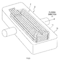
FIG. 5 is a view showing an example of a form of use of aheat exchanger 1. - As shown in
FIG. 5 , aheat exchanger 1 houses a heat-transfer pipe group 2 in a housing space (a space inside a housing 10) 11. Theheat exchanger 1 is configured such that an external fluid introduced from outside flows through thehousing space 11 and is discharged from thehousing space 11, to thereby perform heat exchange between the external fluid and an internal fluid flowing insidepipes 2a-2h. - In the present embodiment, the heat-
transfer pipe group 2 includes afirst pipe set 2x and a second pipe set 2y, as shown inFIG. 1 . Thefirst pipe set 2x includespipes pipes 2e, 2f, 2g and 2h. - Each of the
pipes 2a-2h is formed to have a spiral shape. This spiral shape can also be described as helical shape. Each of thepipes 2a-2h has each different outside diameter of the spiral shape. In other words, sizes of areas spirally surrounded by therespective pipes 2a-2h are different. - The first pipe set 2x and the second pipe set 2y are stacked along a stacking direction d3, while relatively shifted slightly with respect to each other in a flowing direction d1 of the external fluid (see
FIGS. 3A-3D ). The stacking direction d3 is interpreted as a direction perpendicular to an alignment direction of thepipes 2a-2d, or analignment direction 2e∼2h (the same as the flowing direction d1 of the external fluid) (seeFIG. 1 ). - Taking an example of the relationship between the two
pipes pipe 2a is located upstream from thepipe 2e in the flowing direction d1 of the external fluid, and thereby thepipe 2a and thepipe 2e are relatively shifted with respect to each other in the flowing direction d1 of the external fluid (seeFIGS. 3A-3D ). Thepipe 2a and thepipe 2e are also relatively shifted with respect to each other in the stacking direction d3 (the vertical direction). That is, thepipe 2a and thepipe 2e are stacked in the stacking direction d3 (the vertical direction) and also are relatively shifted with respect to each other in the flowing direction d1. - Also, in the present embodiment,
spacers 3 are disposed in the heat-transfer pipe group 2 at both longitudinal end sides of the heat-transfer pipe group 2. Specifically, thespacers 3 are disposed between thefirst pipe set 2x and the second pipe set 2y at the both longitudinal end sides of the heat-transfer group 2. - The
pipes 2a-2h includes sections disposed in a direction crossing a flow path of the external fluid on each of an upstream side and a downstream side of the flow path. A specific explanation is provided here regarding the first pipe set 2x. The second pipe set 2y (i.e., thepipes 2e-2h), of which a detailed explanation is omitted, has the same structure as the first pipe set 2x. Thepipe 2a has a section on the upstream side (hereinafter referred to as the "upstream pipe") 22a and a section on the downstream side (hereinafter referred to as the "downstream pipe") 24a. Thepipe 2b has anupstream pipe 22b and adownstream pipe 24b, thepipe 2c has anupstream pipe 22c and adownstream pipe 24c, and thepipe 2d has anupstream pipe 22d and adownstream pipe 24d. Hereinafter, theupstream pipes 22a-22d and upstream pipes (not specifically shown) of thepipes 2e-2h are also collectively referred to as the "upstream pipe 22". Also, thedownstream pipes 24a-24d and downstream pipes (not specifically shown) of thepipes 2e-2h are also collectively referred to as the "downstream pipe 24". The external fluid flows crossing over theupstream pipe 22 of thepipes 2a-2h, and then flows crossing over thedownstream pipe 24 of thepipes 2a-2h. - When the
heat exchanger 1 is disposed in a state of use, each of theupstream pipe 22 and thedownstream pipe 24 is tilted with respect to a horizontal plane, as shown inFIG. 2 . Theupstream pipe 22 and thedownstream pipe 24 are arranged in a positional relationship such that anaxis 12 of theupstream pipe 22 crosses anaxis 14 of thedownstream pipe 24 in a projected plan view when thehousing space 11 is projected from the upstream side toward the downstream side of the flow path. - Specifically, one of the
axis 12 of theupstream pipe 22 and theaxis 14 of thedownstream pipe 24 is relatively tilted with respect to the other, and thereby theaxis 12 of theupstream pipe 22 crosses theaxis 14 of thedownstream pipe 24. - In the present embodiment, the
upstream pipe 22 and thedownstream pipe 24 are configured to have a same length and a same tilting angle. "Have the same tilting angle" here means that interior angles with respect to a horizontal plane are the same. More specifically, an interior angle α formed by the horizontal plane and theupstream pipe 22 and an interior angle β formed by the horizontal plane and thedownstream pipe 24 are the same. As a result, theaxis 12 of theupstream pipe 22 and theaxis 14 of thedownstream pipe 24 cross each another in a position γ in a longitudinal direction d2 of thepipes 2a-2h obtained by equally dividing a length of each of thepipes 2a-2h by the number of the stacked pipe sets. For example, when the first pipe set 2x and thesecond pipe set 2y are arranged as in the present embodiment (i.e., arranged in two layers), theaxis 12 and theaxis 14 cross each other in the position γ obtained by bisecting a length (L) of theupstream pipe 22 and a length (L') (L=L' in the present case) of thedownstream pipe 24 in the longitudinal direction of theupstream pipe 22 and thedownstream pipe 24, as shown inFIG. 2 . - Although the
upstream pipe 22 and thedownstream pipe 24 may have the same tilting angle, thedownstream pipe 24 may have a tilting angle larger than theupstream pipe 22. Specifically, the interior angle β formed by the horizontal plane and thedownstream pipe 24 may be larger than the interior angle α formed by the horizontal plane and theupstream pipe 22. - In addition, as shown in
FIGS. 3A-3D , the first pipe set 2x and thesecond pipe set 2y are relatively shifted with respect to each other in the flowing direction d1 of the external fluid. - According to the
heat exchanger 1 in the present embodiment, each of theupstream pipe 22 and thedownstream pipe 24 is tilted with respect to the horizontal plane. Accordingly, drain, even if attached to theupstream pipe 22 and thedownstream pipe 24 as a result of heat exchange, can be made to flow along tilts of theupstream pipe 22 and thedownstream pipe 24, which are tilted with respect to the horizontal planes, toward side areas of the flow path. As a result, the drain is unlikely to remain. Thus, heat exchange is unlikely to be hindered by remaining drain attached to each of theupstream pipe 22 and thedownstream pipe 24, and thereby an efficiency of heat exchange can be maintained. - According to the configuration as above, the
upstream pipe 22 and thedownstream pipe 24 are arranged in the positional relationship such that theaxis 12 of theupstream pipe 22 and theaxis 14 of thedownstream pipe 24 cross each other in the projected plan view when thehousing space 11 is projected from the upstream side toward the downstream side of the flow path of the external fluid. This configuration can reduce areas through which the external fluid simply passes (areas in which theupstream pipe 22 or the downstream pipe is not present inFIG. 2 ) in the flowing direction of the external fluid, as compared with the case where such a positional relationship that theaxis 12 of theupstream pipe 22 and theaxis 14 of thedownstream pipe 24 cross each other in the projected plan view is not employed (for example, theaxis 12 and theaxis 14 are parallel and overlapped in the projected plan view). Thus, the external fluid flowing through thehousing space 11 more easily contacts theupstream pipe 22 and thedownstream pipe 24, and thereby a more improved efficiency of heat exchange can be achieved. - In the above embodiment, since the first pipe set 2x and the
second pipe set 2y are relatively shifted with respect to each other in the flowing direction d1 of the external fluid, flow of the external fluid is more likely to be disturbed, as compared with the case where the pipe sets are not shifted with respect to each other. Thus, the external fluid is more likely to contact the first pipe set 2x and the second pipe set 2y, and thereby a further improved efficiency of heat exchange can be achieved. - In a case where the
pipes 2a-2h are configured such that the tilting angle of thedownstream pipe 24 is larger than the tilting angle of theupstream pipe 22, areas through which the external fluid simply passes can be reduced, as compared with the case where all the tilting angles of theupstream pipe 22 and thedownstream pipe 24 are the same. Specifically, when theupstream pipe 22 and thedownstream pipe 24 are projected from the upstream side toward the downstream side of the flow path, areas among thepipes 2a-2h can be reduced. Thus, the external fluid flowing through thehousing space 11 more easily contacts theupstream pipe 22 and thedownstream pipe 24, and thereby a more improved efficiency of heat exchange can be achieved. - In the above embodiment, the
pipes 2a-2h correspond to examples of a heat-transfer pipe and a spiral heat-transfer pipe, theupstream pipe 22 corresponds to the upstream heat-transfer pipe section, and thedownstream pipe 24 corresponds to the downstream heat-transfer pipe section. - Although a preferred embodiment of the present invention has been described above, it should be understood that the present invention is not at all limited to the above-described embodiment, but may be practiced in various forms within the technical scope of the present invention.
- For example, while the first pipe set 2x and the
second pipe set 2y are arranged to form double spirals in the above-described embodiment, three or more pipe sets may be arranged to form triple or more spirals. Also, the length (L) (seeFIG. 2 ) of theupstream pipe 22 and the length (L') (seeFIG. 2 ) of thedownstream pipe 24 may be different. - Further, the tilting angle of the
upstream pipe 22 and the tilting angle of thedownstream pipe 24 may be different. That is, the interior angle α (seeFIG. 2 ) formed by the horizontal plane and theupstream pipe 22, and the interior angle β (seeFIG. 2 ) formed by the horizontal plane and thedownstream pipe 24 may be different. In this case, such a configuration may be possible that the length of theupstream pipe 22 and the length of thedownstream pipe 24 is different and also the tilting angle of theupstream pipe 22 and the tilting angle of thedownstream pipe 24 are different. - Moreover, the
heat exchanger 1 in the above embodiment may be constituted by only one of the first pipe set 2x and the second pipe set 2y. In this case, by tilting a connectingsection 26 for connecting theupstream pipe 22 and thedownstream pipe 24 in the single pipe set with respect to the flowing direction of the external fluid, theupstream pipe 22 and thedownstream pipe 24 may be configured to cross each other, as shown inFIGS. 4A and 4B . - Also, a direction of shifting the first pipe set 2x with respect to the second pipe set 2y in the above-described embodiment is not limited to the direction of the flow path as long as the flow of the external fluid is likely to be disturbed by the shifting.
- Further, the
pipes 2a-2h may be configured such that when thepipes 2a-2h are projected from the upstream side toward the downstream side of the flow path of the external fluid, theaxis 12 of theupstream pipe 22 and theaxis 14 of thedownstream pipe 24 cross each other only in part in the projected plan view. More specifically, only a part of theupstream pipe 22 and only a part of thedownstream pipe 24 may be relatively tilted with each other, and thereby the part of theupstream pipe 22 and the part of thedownstream pipe 24 cross each other. In this case, the remaining part of theupstream pipe 22 and the remaining part of thedownstream pipe 24 may be parallel.
Claims (9)
- A heat exchanger (1) comprising:a heat-transfer pipe (2a-2h) for heat exchange,wherein the heat exchanger (1) is configured such that heat exchange is performed between an external fluid flowing outside the heat-transfer pipe (2a-2h) and the heat-transfer pipe (2a-2h), the heat-transfer pipe (2a-2h) being a spiral heat-transfer pipe (2a-2h) having a spiral shape,wherein the spiral heat-transfer pipe (2a-2h) includes:an upstream heat-transfer pipe section (22) disposed on an upstream side of a flow path of the external fluid in a direction crossing the flow path; anda downstream heat-transfer pipe section (24) disposed on a downstream side of the flow path in a direction crossing the flow path, andwherein each of an axis (12) of the upstream heat-transfer pipe section (22) and an axis (14) of the downstream heat-transfer pipe section (24) in the spiral heat-transfer pipe (2a-2h) is tilted with respect to a horizontal plane, and also is relatively tilted with respect to the other of the axes (12, 14), so that the axis (12) of the upstream heat-transfer pipe section (22) crosses the axis (14) of the downstream heat-transfer pipe section (24).
- The heat exchanger (1) according to claim 1, further comprising:a housing space (11) for housing the spiral heat-transfer pipe (2a-2h),wherein the heat exchanger (1) is configured such that the external fluid is discharged after flowing through the housing space (11), to thereby perform heat exchange between the external fluid and an internal fluid flowing inside the spiral heat-transfer pipe (2a-2h).
- The heat exchanger (1) according to claim 2, wherein a plurality of the spiral heat-transfer pipes (2a-2h) are housed in the housing space (11) so as to form multiple spirals.
- The heat exchanger (1) according to claim 3, wherein each of the plurality of the spiral heat-transfer pipes (2a-2h) is relatively shifted in a predetermined direction with respect to the other spiral heat-transfer pipes (2a-2h).
- The heat exchanger (1) according to claim 3 or 4, wherein the plurality of the spiral heat-transfer pipes (2a-2h) are stacked in a direction crossing a flowing direction (d1) of the external fluid so as to form multiple spirals.
- The heat exchanger (1) according to claim 4, wherein each of the plurality of the spiral heat-transfer pipes (2a-2h) is relatively shifted in a direction crossing a neighboring direction of the spiral heat-transfer pipes (2a-2h) with respect to the other spiral heat-transfer pipes (2a-2h).
- The heat exchanger (1) according to claim 4, wherein, at least in a relationship between two most neighboring spiral heat-transfer pipes ((2a,2e),(2b,2f),(2c,2g),(2d,2h)), one of the spiral heat-transfer pipes ((2a,2e),(2b,2f),(2c,2g),(2d,2h)) is located upstream from the other in the flow path of the external fluid, so that the two spiral heat-transfer pipes ((2a,2e),(2b,2f),(2c,2g),(2d,2h)) are relatively shifted with respect to each other.
- The heat exchanger (1) according to claim 4, wherein the each of the plurality of the spiral heat-transfer pipes (2a-2h) is relatively shifted with respect to the other spiral heat-transfer pipes (2a-2h) in the flowing direction (d1) of the external fluid.
- The heat exchanger (1) according to claims 1 to 8, wherein when the spiral heat-transfer pipe (2a-2h) is projected from the upstream side toward the downstream side of the flow path of the external fluid, the axis (12) of the upstream heat-transfer pipe section (22) and the axis (14) of the downstream heat-transfer pipe section (24) cross each other in a projected plan view.
Applications Claiming Priority (1)
| Application Number | Priority Date | Filing Date | Title |
|---|---|---|---|
| JP2009191138A JP5073719B2 (en) | 2009-08-20 | 2009-08-20 | Heat exchanger |
Publications (4)
| Publication Number | Publication Date |
|---|---|
| EP2295913A2 true EP2295913A2 (en) | 2011-03-16 |
| EP2295913A3 EP2295913A3 (en) | 2011-12-07 |
| EP2295913A8 EP2295913A8 (en) | 2012-02-22 |
| EP2295913B1 EP2295913B1 (en) | 2013-06-05 |
Family
ID=43242286
Family Applications (1)
| Application Number | Title | Priority Date | Filing Date |
|---|---|---|---|
| EP10173013.3A Active EP2295913B1 (en) | 2009-08-20 | 2010-08-17 | Heat exchanger with tilted pipe sections |
Country Status (5)
| Country | Link |
|---|---|
| US (1) | US20110042039A1 (en) |
| EP (1) | EP2295913B1 (en) |
| JP (1) | JP5073719B2 (en) |
| AU (1) | AU2010212319B2 (en) |
| ES (1) | ES2417322T3 (en) |
Families Citing this family (4)
| Publication number | Priority date | Publication date | Assignee | Title |
|---|---|---|---|---|
| EP2684002B1 (en) * | 2011-03-07 | 2019-05-08 | Aavid Thermalloy, LLC | Thermal transfer device with spiral fluid pathways |
| CN104067056A (en) * | 2012-04-05 | 2014-09-24 | 朱宏锋 | Cooking stove |
| IT201700096656A1 (en) * | 2017-08-28 | 2019-02-28 | Cosmogas Srl | HEAT EXCHANGER FOR A BOILER, AND HEAT EXCHANGER TUBE |
| CN110595066B (en) * | 2019-08-07 | 2021-08-06 | 西安交通大学 | Full-premixing condensing type gas heat exchange equipment and heat exchange method |
Citations (2)
| Publication number | Priority date | Publication date | Assignee | Title |
|---|---|---|---|---|
| JP2008025976A (en) | 2006-07-25 | 2008-02-07 | Noritz Corp | Heat exchanger and hot water device |
| JP2008032252A (en) | 2006-07-26 | 2008-02-14 | Noritz Corp | Heat exchanger and water heater |
Family Cites Families (20)
| Publication number | Priority date | Publication date | Assignee | Title |
|---|---|---|---|---|
| DE1119883B (en) * | 1955-08-12 | 1961-12-21 | Helmut Baelz Ges Fuer Patentve | Standing steam-heated heat exchanger with helically tightly wound heating pipes |
| US3874345A (en) * | 1974-02-11 | 1975-04-01 | Hydrogen Corp | Vapor generator |
| JPS5135148A (en) * | 1974-09-13 | 1976-03-25 | Shell Int Research | Netsukokanki oyobi kanetsugasureikyakuho |
| GB2099871B (en) * | 1981-04-21 | 1984-10-31 | Unilever Plc | Fabric conditioning composition |
| US4872503A (en) * | 1986-03-13 | 1989-10-10 | Marriner Raymond E | Air heat exchanger |
| JPS62297696A (en) * | 1986-06-17 | 1987-12-24 | Aipii:Kk | Heat exchanger for refrigerant |
| FR2700608B1 (en) * | 1993-01-15 | 1995-04-07 | Joseph Le Mer | Heat exchanger element, method and device for manufacturing it. |
| US6721721B1 (en) * | 2000-06-15 | 2004-04-13 | International Business Machines Corporation | Virus checking and reporting for computer database search results |
| US7093239B1 (en) * | 2000-07-14 | 2006-08-15 | Internet Security Systems, Inc. | Computer immune system and method for detecting unwanted code in a computer system |
| US8438241B2 (en) * | 2001-08-14 | 2013-05-07 | Cisco Technology, Inc. | Detecting and protecting against worm traffic on a network |
| US7272782B2 (en) * | 2003-12-19 | 2007-09-18 | Backweb Technologies, Inc. | System and method for providing offline web application, page, and form access in a networked environment |
| US20050188361A1 (en) * | 2004-02-23 | 2005-08-25 | Henry Cai | Browser-based web site generation system and method |
| US7461339B2 (en) * | 2004-10-21 | 2008-12-02 | Trend Micro, Inc. | Controlling hostile electronic mail content |
| US20060136374A1 (en) * | 2004-12-17 | 2006-06-22 | Microsoft Corporation | System and method for utilizing a search engine to prevent contamination |
| JP4655621B2 (en) * | 2004-12-22 | 2011-03-23 | 株式会社ノーリツ | Water heater |
| JP2006242458A (en) * | 2005-03-02 | 2006-09-14 | Denso Corp | Heat exchanger, heat exchanger core and method of manufacturing heat exchanger |
| US7464671B2 (en) * | 2006-07-17 | 2008-12-16 | Babcock & Wilcox Power Generation Group, Inc. | Heat exchanger framework |
| JP2009019858A (en) * | 2007-07-13 | 2009-01-29 | Noritz Corp | Heat exchanger and water heater |
| US10027688B2 (en) * | 2008-08-11 | 2018-07-17 | Damballa, Inc. | Method and system for detecting malicious and/or botnet-related domain names |
| JP4963126B2 (en) * | 2009-06-25 | 2012-06-27 | 株式会社パロマ | Spacers, fixing members and heat exchangers |
-
2009
- 2009-08-20 JP JP2009191138A patent/JP5073719B2/en active Active
-
2010
- 2010-08-13 AU AU2010212319A patent/AU2010212319B2/en active Active
- 2010-08-17 ES ES10173013T patent/ES2417322T3/en active Active
- 2010-08-17 US US12/858,289 patent/US20110042039A1/en not_active Abandoned
- 2010-08-17 EP EP10173013.3A patent/EP2295913B1/en active Active
Patent Citations (2)
| Publication number | Priority date | Publication date | Assignee | Title |
|---|---|---|---|---|
| JP2008025976A (en) | 2006-07-25 | 2008-02-07 | Noritz Corp | Heat exchanger and hot water device |
| JP2008032252A (en) | 2006-07-26 | 2008-02-14 | Noritz Corp | Heat exchanger and water heater |
Also Published As
| Publication number | Publication date |
|---|---|
| EP2295913B1 (en) | 2013-06-05 |
| US20110042039A1 (en) | 2011-02-24 |
| EP2295913A8 (en) | 2012-02-22 |
| AU2010212319B2 (en) | 2015-06-25 |
| ES2417322T3 (en) | 2013-08-07 |
| AU2010212319A1 (en) | 2011-03-10 |
| JP2011043281A (en) | 2011-03-03 |
| JP5073719B2 (en) | 2012-11-14 |
| EP2295913A3 (en) | 2011-12-07 |
Similar Documents
| Publication | Publication Date | Title |
|---|---|---|
| US7406998B2 (en) | Heat storing device | |
| RU2606466C2 (en) | Plate of heat exchanger and plate heat exchanger containing such plate of heat exchanger | |
| EP2295913A2 (en) | Spiral pipe heat excahnger with tilted pipe sections | |
| US20070227712A1 (en) | Heat exchanger apparatus incorporating elliptically-shaped serpentine tube bodies | |
| US11892245B2 (en) | Heat exchanger including furcating unit cells | |
| JP2007248047A (en) | Layered heat exchanger | |
| EP3249333B1 (en) | Refrigerant heat exchanger | |
| EP2981780B1 (en) | Plate heat exchanger and method for constructing multiple passes in the plate heat exchanger | |
| JP2017198440A (en) | Heat exchanger and air conditioner | |
| JP2006336890A (en) | Intercooler | |
| US20130146262A1 (en) | Double pipe heat exchanger having multi-directional connector and air conditioner for vehicle including the same | |
| JPWO2014181404A1 (en) | Heat exchanger | |
| EP2770289A1 (en) | Heat exchange apparatus | |
| CN110887395A (en) | Radiating tube and radiator | |
| US20190137197A1 (en) | Printed circuit-type heat exchanger having integral structure | |
| AU2010212318B2 (en) | Heat Exchanger | |
| KR101764113B1 (en) | Heat Exchanger | |
| CN216159687U (en) | Heat exchange assembly | |
| JP5328961B2 (en) | Heat exchanger | |
| EP3551954B1 (en) | Recuperator | |
| JP2017133790A (en) | Heat exchanger | |
| CN220507812U (en) | Microchannel single-row zigzag fin, fin assembly and heat exchanger | |
| US12031778B2 (en) | Plate-and-shell heat exchanger and a heat transfer plate for a plate-and-shell heat exchanger | |
| US20240280326A1 (en) | Micro-channel heat exchanger | |
| CN220418170U (en) | Heat exchanger |
Legal Events
| Date | Code | Title | Description |
|---|---|---|---|
| PUAI | Public reference made under article 153(3) epc to a published international application that has entered the european phase |
Free format text: ORIGINAL CODE: 0009012 |
|
| AK | Designated contracting states |
Kind code of ref document: A2 Designated state(s): AL AT BE BG CH CY CZ DE DK EE ES FI FR GB GR HR HU IE IS IT LI LT LU LV MC MK MT NL NO PL PT RO SE SI SK SM TR |
|
| AX | Request for extension of the european patent |
Extension state: BA ME RS |
|
| RAP1 | Party data changed (applicant data changed or rights of an application transferred) |
Owner name: PALOMA CO., LTD. |
|
| PUAL | Search report despatched |
Free format text: ORIGINAL CODE: 0009013 |
|
| AK | Designated contracting states |
Kind code of ref document: A3 Designated state(s): AL AT BE BG CH CY CZ DE DK EE ES FI FR GB GR HR HU IE IS IT LI LT LU LV MC MK MT NL NO PL PT RO SE SI SK SM TR |
|
| AX | Request for extension of the european patent |
Extension state: BA ME RS |
|
| RIC1 | Information provided on ipc code assigned before grant |
Ipc: F28D 7/02 20060101AFI20111028BHEP Ipc: F28F 9/013 20060101ALI20111028BHEP Ipc: F28D 7/16 20060101ALI20111028BHEP |
|
| RTI1 | Title (correction) |
Free format text: SPIRAL PIPE HEAT EXCHANGER WITH TILTED PIPE SECTIONS |
|
| 17P | Request for examination filed |
Effective date: 20120531 |
|
| 17Q | First examination report despatched |
Effective date: 20121008 |
|
| GRAP | Despatch of communication of intention to grant a patent |
Free format text: ORIGINAL CODE: EPIDOSNIGR1 |
|
| RIC1 | Information provided on ipc code assigned before grant |
Ipc: F28D 7/02 20060101AFI20130212BHEP Ipc: F28F 9/013 20060101ALI20130212BHEP Ipc: F28F 17/00 20060101ALI20130212BHEP Ipc: F28D 7/16 20060101ALI20130212BHEP |
|
| RAP1 | Party data changed (applicant data changed or rights of an application transferred) |
Owner name: PALOMA CO., LTD. |
|
| RIN1 | Information on inventor provided before grant (corrected) |
Inventor name: ANDO, YOSHIO Inventor name: SANO, YASUHIRO |
|
| GRAS | Grant fee paid |
Free format text: ORIGINAL CODE: EPIDOSNIGR3 |
|
| GRAA | (expected) grant |
Free format text: ORIGINAL CODE: 0009210 |
|
| AK | Designated contracting states |
Kind code of ref document: B1 Designated state(s): AL AT BE BG CH CY CZ DE DK EE ES FI FR GB GR HR HU IE IS IT LI LT LU LV MC MK MT NL NO PL PT RO SE SI SK SM TR |
|
| REG | Reference to a national code |
Ref country code: GB Ref legal event code: FG4D |
|
| REG | Reference to a national code |
Ref country code: CH Ref legal event code: EP |
|
| REG | Reference to a national code |
Ref country code: AT Ref legal event code: REF Ref document number: 615898 Country of ref document: AT Kind code of ref document: T Effective date: 20130615 |
|
| REG | Reference to a national code |
Ref country code: IE Ref legal event code: FG4D |
|
| REG | Reference to a national code |
Ref country code: DE Ref legal event code: R096 Ref document number: 602010007512 Country of ref document: DE Effective date: 20130801 |
|
| REG | Reference to a national code |
Ref country code: ES Ref legal event code: FG2A Ref document number: 2417322 Country of ref document: ES Kind code of ref document: T3 Effective date: 20130807 |
|
| REG | Reference to a national code |
Ref country code: AT Ref legal event code: MK05 Ref document number: 615898 Country of ref document: AT Kind code of ref document: T Effective date: 20130605 |
|
| PG25 | Lapsed in a contracting state [announced via postgrant information from national office to epo] |
Ref country code: AT Free format text: LAPSE BECAUSE OF FAILURE TO SUBMIT A TRANSLATION OF THE DESCRIPTION OR TO PAY THE FEE WITHIN THE PRESCRIBED TIME-LIMIT Effective date: 20130605 Ref country code: SI Free format text: LAPSE BECAUSE OF FAILURE TO SUBMIT A TRANSLATION OF THE DESCRIPTION OR TO PAY THE FEE WITHIN THE PRESCRIBED TIME-LIMIT Effective date: 20130605 Ref country code: SE Free format text: LAPSE BECAUSE OF FAILURE TO SUBMIT A TRANSLATION OF THE DESCRIPTION OR TO PAY THE FEE WITHIN THE PRESCRIBED TIME-LIMIT Effective date: 20130605 Ref country code: GR Free format text: LAPSE BECAUSE OF FAILURE TO SUBMIT A TRANSLATION OF THE DESCRIPTION OR TO PAY THE FEE WITHIN THE PRESCRIBED TIME-LIMIT Effective date: 20130906 Ref country code: LT Free format text: LAPSE BECAUSE OF FAILURE TO SUBMIT A TRANSLATION OF THE DESCRIPTION OR TO PAY THE FEE WITHIN THE PRESCRIBED TIME-LIMIT Effective date: 20130605 Ref country code: FI Free format text: LAPSE BECAUSE OF FAILURE TO SUBMIT A TRANSLATION OF THE DESCRIPTION OR TO PAY THE FEE WITHIN THE PRESCRIBED TIME-LIMIT Effective date: 20130605 Ref country code: NO Free format text: LAPSE BECAUSE OF FAILURE TO SUBMIT A TRANSLATION OF THE DESCRIPTION OR TO PAY THE FEE WITHIN THE PRESCRIBED TIME-LIMIT Effective date: 20130905 |
|
| REG | Reference to a national code |
Ref country code: NL Ref legal event code: VDEP Effective date: 20130605 |
|
| REG | Reference to a national code |
Ref country code: LT Ref legal event code: MG4D |
|
| PG25 | Lapsed in a contracting state [announced via postgrant information from national office to epo] |
Ref country code: HR Free format text: LAPSE BECAUSE OF FAILURE TO SUBMIT A TRANSLATION OF THE DESCRIPTION OR TO PAY THE FEE WITHIN THE PRESCRIBED TIME-LIMIT Effective date: 20130605 Ref country code: BG Free format text: LAPSE BECAUSE OF FAILURE TO SUBMIT A TRANSLATION OF THE DESCRIPTION OR TO PAY THE FEE WITHIN THE PRESCRIBED TIME-LIMIT Effective date: 20130905 |
|
| PG25 | Lapsed in a contracting state [announced via postgrant information from national office to epo] |
Ref country code: LV Free format text: LAPSE BECAUSE OF FAILURE TO SUBMIT A TRANSLATION OF THE DESCRIPTION OR TO PAY THE FEE WITHIN THE PRESCRIBED TIME-LIMIT Effective date: 20130605 |
|
| PG25 | Lapsed in a contracting state [announced via postgrant information from national office to epo] |
Ref country code: IS Free format text: LAPSE BECAUSE OF FAILURE TO SUBMIT A TRANSLATION OF THE DESCRIPTION OR TO PAY THE FEE WITHIN THE PRESCRIBED TIME-LIMIT Effective date: 20131005 Ref country code: SK Free format text: LAPSE BECAUSE OF FAILURE TO SUBMIT A TRANSLATION OF THE DESCRIPTION OR TO PAY THE FEE WITHIN THE PRESCRIBED TIME-LIMIT Effective date: 20130605 Ref country code: CZ Free format text: LAPSE BECAUSE OF FAILURE TO SUBMIT A TRANSLATION OF THE DESCRIPTION OR TO PAY THE FEE WITHIN THE PRESCRIBED TIME-LIMIT Effective date: 20130605 Ref country code: EE Free format text: LAPSE BECAUSE OF FAILURE TO SUBMIT A TRANSLATION OF THE DESCRIPTION OR TO PAY THE FEE WITHIN THE PRESCRIBED TIME-LIMIT Effective date: 20130605 Ref country code: BE Free format text: LAPSE BECAUSE OF FAILURE TO SUBMIT A TRANSLATION OF THE DESCRIPTION OR TO PAY THE FEE WITHIN THE PRESCRIBED TIME-LIMIT Effective date: 20130605 Ref country code: PT Free format text: LAPSE BECAUSE OF FAILURE TO SUBMIT A TRANSLATION OF THE DESCRIPTION OR TO PAY THE FEE WITHIN THE PRESCRIBED TIME-LIMIT Effective date: 20131007 |
|
| PG25 | Lapsed in a contracting state [announced via postgrant information from national office to epo] |
Ref country code: NL Free format text: LAPSE BECAUSE OF FAILURE TO SUBMIT A TRANSLATION OF THE DESCRIPTION OR TO PAY THE FEE WITHIN THE PRESCRIBED TIME-LIMIT Effective date: 20130605 Ref country code: RO Free format text: LAPSE BECAUSE OF FAILURE TO SUBMIT A TRANSLATION OF THE DESCRIPTION OR TO PAY THE FEE WITHIN THE PRESCRIBED TIME-LIMIT Effective date: 20130605 Ref country code: PL Free format text: LAPSE BECAUSE OF FAILURE TO SUBMIT A TRANSLATION OF THE DESCRIPTION OR TO PAY THE FEE WITHIN THE PRESCRIBED TIME-LIMIT Effective date: 20130605 |
|
| PLBE | No opposition filed within time limit |
Free format text: ORIGINAL CODE: 0009261 |
|
| STAA | Information on the status of an ep patent application or granted ep patent |
Free format text: STATUS: NO OPPOSITION FILED WITHIN TIME LIMIT |
|
| PG25 | Lapsed in a contracting state [announced via postgrant information from national office to epo] |
Ref country code: DK Free format text: LAPSE BECAUSE OF FAILURE TO SUBMIT A TRANSLATION OF THE DESCRIPTION OR TO PAY THE FEE WITHIN THE PRESCRIBED TIME-LIMIT Effective date: 20130605 Ref country code: MC Free format text: LAPSE BECAUSE OF FAILURE TO SUBMIT A TRANSLATION OF THE DESCRIPTION OR TO PAY THE FEE WITHIN THE PRESCRIBED TIME-LIMIT Effective date: 20130605 |
|
| 26N | No opposition filed |
Effective date: 20140306 |
|
| REG | Reference to a national code |
Ref country code: IE Ref legal event code: MM4A |
|
| REG | Reference to a national code |
Ref country code: DE Ref legal event code: R097 Ref document number: 602010007512 Country of ref document: DE Effective date: 20140306 |
|
| PG25 | Lapsed in a contracting state [announced via postgrant information from national office to epo] |
Ref country code: IE Free format text: LAPSE BECAUSE OF NON-PAYMENT OF DUE FEES Effective date: 20130817 |
|
| REG | Reference to a national code |
Ref country code: CH Ref legal event code: PL |
|
| PG25 | Lapsed in a contracting state [announced via postgrant information from national office to epo] |
Ref country code: CH Free format text: LAPSE BECAUSE OF NON-PAYMENT OF DUE FEES Effective date: 20140831 Ref country code: LI Free format text: LAPSE BECAUSE OF NON-PAYMENT OF DUE FEES Effective date: 20140831 |
|
| PG25 | Lapsed in a contracting state [announced via postgrant information from national office to epo] |
Ref country code: SM Free format text: LAPSE BECAUSE OF FAILURE TO SUBMIT A TRANSLATION OF THE DESCRIPTION OR TO PAY THE FEE WITHIN THE PRESCRIBED TIME-LIMIT Effective date: 20130605 |
|
| PG25 | Lapsed in a contracting state [announced via postgrant information from national office to epo] |
Ref country code: MT Free format text: LAPSE BECAUSE OF FAILURE TO SUBMIT A TRANSLATION OF THE DESCRIPTION OR TO PAY THE FEE WITHIN THE PRESCRIBED TIME-LIMIT Effective date: 20130605 Ref country code: TR Free format text: LAPSE BECAUSE OF FAILURE TO SUBMIT A TRANSLATION OF THE DESCRIPTION OR TO PAY THE FEE WITHIN THE PRESCRIBED TIME-LIMIT Effective date: 20130605 Ref country code: CY Free format text: LAPSE BECAUSE OF FAILURE TO SUBMIT A TRANSLATION OF THE DESCRIPTION OR TO PAY THE FEE WITHIN THE PRESCRIBED TIME-LIMIT Effective date: 20130605 |
|
| PG25 | Lapsed in a contracting state [announced via postgrant information from national office to epo] |
Ref country code: MK Free format text: LAPSE BECAUSE OF FAILURE TO SUBMIT A TRANSLATION OF THE DESCRIPTION OR TO PAY THE FEE WITHIN THE PRESCRIBED TIME-LIMIT Effective date: 20130605 Ref country code: LU Free format text: LAPSE BECAUSE OF NON-PAYMENT OF DUE FEES Effective date: 20130817 Ref country code: HU Free format text: LAPSE BECAUSE OF FAILURE TO SUBMIT A TRANSLATION OF THE DESCRIPTION OR TO PAY THE FEE WITHIN THE PRESCRIBED TIME-LIMIT; INVALID AB INITIO Effective date: 20100817 |
|
| REG | Reference to a national code |
Ref country code: FR Ref legal event code: PLFP Year of fee payment: 7 |
|
| REG | Reference to a national code |
Ref country code: FR Ref legal event code: PLFP Year of fee payment: 8 |
|
| REG | Reference to a national code |
Ref country code: FR Ref legal event code: PLFP Year of fee payment: 9 |
|
| PG25 | Lapsed in a contracting state [announced via postgrant information from national office to epo] |
Ref country code: AL Free format text: LAPSE BECAUSE OF FAILURE TO SUBMIT A TRANSLATION OF THE DESCRIPTION OR TO PAY THE FEE WITHIN THE PRESCRIBED TIME-LIMIT Effective date: 20130605 |
|
| PGFP | Annual fee paid to national office [announced via postgrant information from national office to epo] |
Ref country code: IT Payment date: 20230711 Year of fee payment: 14 Ref country code: ES Payment date: 20230901 Year of fee payment: 14 |
|
| PGFP | Annual fee paid to national office [announced via postgrant information from national office to epo] |
Ref country code: FR Payment date: 20230703 Year of fee payment: 14 Ref country code: DE Payment date: 20230627 Year of fee payment: 14 |
|
| PGFP | Annual fee paid to national office [announced via postgrant information from national office to epo] |
Ref country code: GB Payment date: 20240627 Year of fee payment: 15 |
|
| REG | Reference to a national code |
Ref country code: DE Ref legal event code: R082 Ref document number: 602010007512 Country of ref document: DE Representative=s name: PRUEFER & PARTNER MBB PATENTANWAELTE RECHTSANW, DE Ref country code: DE Ref legal event code: R081 Ref document number: 602010007512 Country of ref document: DE Owner name: PALOMA RHEEM HOLDINGS CO., LTD., JP Free format text: FORMER OWNER: PALOMA CO., LTD., NAGOYA-SHI, AICHI, JP |