EP2295821A2 - Fastener assembly - Google Patents
Fastener assembly Download PDFInfo
- Publication number
- EP2295821A2 EP2295821A2 EP20100174225 EP10174225A EP2295821A2 EP 2295821 A2 EP2295821 A2 EP 2295821A2 EP 20100174225 EP20100174225 EP 20100174225 EP 10174225 A EP10174225 A EP 10174225A EP 2295821 A2 EP2295821 A2 EP 2295821A2
- Authority
- EP
- European Patent Office
- Prior art keywords
- fastener
- strip
- recesses
- asymmetry
- assembly according
- Prior art date
- Legal status (The legal status is an assumption and is not a legal conclusion. Google has not performed a legal analysis and makes no representation as to the accuracy of the status listed.)
- Granted
Links
- 230000000712 assembly Effects 0.000 claims abstract description 30
- 238000000429 assembly Methods 0.000 claims abstract description 30
- 239000000463 material Substances 0.000 description 4
- 229910000831 Steel Inorganic materials 0.000 description 1
- 238000002485 combustion reaction Methods 0.000 description 1
- 238000006073 displacement reaction Methods 0.000 description 1
- 238000010304 firing Methods 0.000 description 1
- 239000002184 metal Substances 0.000 description 1
- 230000003014 reinforcing effect Effects 0.000 description 1
- 230000000717 retained effect Effects 0.000 description 1
- 239000010959 steel Substances 0.000 description 1
- 239000000758 substrate Substances 0.000 description 1
Images


Classifications
-
- F—MECHANICAL ENGINEERING; LIGHTING; HEATING; WEAPONS; BLASTING
- F16—ENGINEERING ELEMENTS AND UNITS; GENERAL MEASURES FOR PRODUCING AND MAINTAINING EFFECTIVE FUNCTIONING OF MACHINES OR INSTALLATIONS; THERMAL INSULATION IN GENERAL
- F16B—DEVICES FOR FASTENING OR SECURING CONSTRUCTIONAL ELEMENTS OR MACHINE PARTS TOGETHER, e.g. NAILS, BOLTS, CIRCLIPS, CLAMPS, CLIPS OR WEDGES; JOINTS OR JOINTING
- F16B15/00—Nails; Staples
- F16B15/08—Nails; Staples formed in integral series but easily separable
-
- B—PERFORMING OPERATIONS; TRANSPORTING
- B25—HAND TOOLS; PORTABLE POWER-DRIVEN TOOLS; MANIPULATORS
- B25B—TOOLS OR BENCH DEVICES NOT OTHERWISE PROVIDED FOR, FOR FASTENING, CONNECTING, DISENGAGING OR HOLDING
- B25B23/00—Details of, or accessories for, spanners, wrenches, screwdrivers
- B25B23/02—Arrangements for handling screws or nuts
- B25B23/04—Arrangements for handling screws or nuts for feeding screws or nuts
- B25B23/045—Arrangements for handling screws or nuts for feeding screws or nuts using disposable strips or discs carrying the screws or nuts
-
- B—PERFORMING OPERATIONS; TRANSPORTING
- B25—HAND TOOLS; PORTABLE POWER-DRIVEN TOOLS; MANIPULATORS
- B25B—TOOLS OR BENCH DEVICES NOT OTHERWISE PROVIDED FOR, FOR FASTENING, CONNECTING, DISENGAGING OR HOLDING
- B25B23/00—Details of, or accessories for, spanners, wrenches, screwdrivers
- B25B23/02—Arrangements for handling screws or nuts
- B25B23/04—Arrangements for handling screws or nuts for feeding screws or nuts
- B25B23/06—Arrangements for handling screws or nuts for feeding screws or nuts using built-in magazine
-
- B—PERFORMING OPERATIONS; TRANSPORTING
- B25—HAND TOOLS; PORTABLE POWER-DRIVEN TOOLS; MANIPULATORS
- B25C—HAND-HELD NAILING OR STAPLING TOOLS; MANUALLY OPERATED PORTABLE STAPLING TOOLS
- B25C1/00—Hand-held nailing tools; Nail feeding devices
- B25C1/001—Nail feeding devices
- B25C1/005—Nail feeding devices for rows of contiguous nails
-
- F—MECHANICAL ENGINEERING; LIGHTING; HEATING; WEAPONS; BLASTING
- F16—ENGINEERING ELEMENTS AND UNITS; GENERAL MEASURES FOR PRODUCING AND MAINTAINING EFFECTIVE FUNCTIONING OF MACHINES OR INSTALLATIONS; THERMAL INSULATION IN GENERAL
- F16B—DEVICES FOR FASTENING OR SECURING CONSTRUCTIONAL ELEMENTS OR MACHINE PARTS TOGETHER, e.g. NAILS, BOLTS, CIRCLIPS, CLAMPS, CLIPS OR WEDGES; JOINTS OR JOINTING
- F16B43/00—Washers or equivalent devices; Other devices for supporting bolt-heads or nuts
- F16B43/004—Washers or equivalent devices; Other devices for supporting bolt-heads or nuts with a radial cut in order to improve elasticity of the washer
Definitions
- the present invention relates to supports and support collars for elongate fasteners such as nails, pins, screws and the like, and fastener assemblies comprising such supports and support collars mounted on elongate fasteners.
- the invention particularly relates to strips of such fastener assemblies, in which the support collars are joined together, thereby providing strips of collated fasteners.
- the invention also relates to fastener-driving tools for such fastener assembly strips.
- fastener-driving tools include a driver that is propelled rapidly against a fastener to drive a fastener from the tool into a workpiece.
- the driver may comprise a piston, or a ram (impact member), for example.
- the driver may be propelled in any of a variety of ways, including (but not limited to) pneumatically, by combustion, by means of a strap or chain, by means of a separate piston, or by means of one or more flywheels, for example.
- Fastener-driving (or firing) tools have for many years included magazines (i.e. holding and supply devices) for the fasteners that are driven/fired from the tools.
- magazines i.e. holding and supply devices
- magazines There are various known types of such magazines, including magazines arranged to store and supply loose fasteners, magazines for coiled strips of fasteners, and magazines for straight or curved strips of fasteners.
- United States Patent No. 5,069,340 discloses a strip of collated elongate fasteners in which a carrier moulded from a polymeric material has a sleeve for each fastener. Each sleeve has an annular portion, and a breakable portion which breaks into two segments as the fastener gripped by the sleeve is driven from a fastener-driving tool.
- the breakable portion has a pair of similar, laterally opposed, outwardly opening, continuously curved concave recesses with open windows from which portions of the fastener emerges.
- parallel ribs of a guiding device fit into such recesses, so as to guide the strip between such ribs.
- the strip of collated fasteners is advanced incrementally towards a fastener-driving region, such that the leading fastener and its sleeve are driven from the tool into a workpiece.
- United States Patent No. 3,438,487 discloses a carrier for holding a plurality of fasteners with their shanks in a spaced-apart parallel relation, comprising an elongate flexible strip.
- the strip comprises a web transversely spaced apart from the fastener shanks, and a plurality of slotted flanges along the upper and lower edges of the web extending substantially perpendicular to the web, for supporting the shank of each fastener.
- the fastener is separated from the carrier strip, and the carrier strip remains attached to the tool.
- United States Patent No. 3,830,364 discloses a nail carrier for supporting and locating nails to be fed to a power-operated nail driving device.
- the carrier comprises a rigid plate having, on its top side, a first group of rigid studs arranged in two parallel spaced-apart rows and a second group of yielding studs disposed in one row parallel to the other two rows, and extending from the underside of the plate are reinforcing flanges.
- Two studs of the first group in conjunction with one stud of the second group provide a locating position for a nail, and this is repeated along the nail carrier.
- the present invention seeks to provide improved fastener supports and support collars, fastener assemblies, strips of support collars and assemblies, and fastener-driving tools.
- the present invention provides a fastener assembly, comprising an elongate fastener, and a support collar mounted on the fastener, the support collar shaped such that it has profiles on opposite sides of the fastener that are asymmetric with respect to each other.
- a second aspect of the invention provides a support collar for an elongate fastener, the support collar shaped such that it has profiles on opposite sides of a longitudinal axis of the collar that are asymmetric with respect to each other.
- the support collar is mounted on (i.e. around) an elongate fastener such that the fastener extends along the longitudinal axis of the collar.
- the support collar (of the first or second aspect of the invention) preferably comprises a single part, but in some embodiments of the invention the support collar may comprise two or more separate parts which, at least when mounted on a fastener, combine to form the support collar.
- the support collar may comprise two separate collar components which, at least when mounted on a fastener, combine to provide the asymmetric profiles.
- profile of a side of the support collar is meant the outline of that side of the support collar when viewed from a direction substantially perpendicular to that side, i.e. the outline of the side when viewed in profile.
- the asymmetry in the collar profiles on opposite sides of the fastener comprises a longitudinal asymmetry along at least part of the length of the elongate fastener (longitudinal axis).
- the maximum distances, of both opposite profiles, from the longitudinal axis of the collar are substantially equal.
- the profiles on two opposite sides of the fastener preferably each include at least one recess.
- the asymmetry preferably comprises an asymmetry in the recesses on the two opposite sides of the fastener.
- An advantage of the present invention is that the asymmetry in the profiles on opposite sides of the support collar (and thus, on opposite sides of the fastener) can help to prevent the fastener assemblies being inserted into, and/or driven from, a fastener-driving tool in an incorrect orientation.
- a passage within a fastener magazine and/or part of a nose piece of a fastener-driving tool may be provided with corresponding asymmetric profiles arranged to guide the support collar(s) of the invention (e.g. towards an outlet passage for the fasteners), and with which the asymmetric profiles of the support collar(s) are arranged to fit.
- the lack of symmetry on opposite sides of the fastener assemblies can thus require the user to insert the fastener assemblies into the tool in the correct orientation for the tool, and in this way it can lessen the likelihood of fastener assemblies jamming in the tool, etc.
- the asymmetry in the profiles can help to provide improved guidance of the fastener assemblies in a fastener-driving tool (e.g. in a magazine and/or in a nose piece).
- a fastener-driving tool e.g. in a magazine and/or in a nose piece.
- the support collar has symmetric profiles on opposite sides of the fastener, with identically positioned and shaped single recesses on each side, each of which cooperates with a single respective protruding rib in a passage of a fastener-driving tool.
- a fastener assembly is provided with two recesses on one side, and a single recess (or three recesses) on the opposite side, there may be less chance of the recesses of the fastener assembly rotating about their respective protruding ribs, and thus less chance of jamming.
- the provision of a single recess on one side, and two recesses on the opposite side, is a particularly simple and convenient way of achieving this, for example.
- a further possible advantage of the invention concerns the performance of a fastener in use, after it has been driven from a fastening-driving tool.
- any resilient compressibility provided by the support collar can prevent such a gap appearing or widening over time (e.g.
- a disadvantage of the type of symmetrical support collar disclosed in US 5,069,340 is that the part of the support collar that remains attached to the fastener is an annular block of material, which has moderately low resilient compressibility.
- additional resilient compressibility i.e. "springiness"
- the profiles on the two opposite sides of the fastener may each include at least one recess.
- the asymmetry may thus comprise an asymmetry in the number of recesses.
- the support collar may have a single recess on one side of the fastener, and two or more recesses on the opposite side of the fastener, or the support collar may have two recesses on one side of the fastener, and three or more recesses on the opposite side of the fastener. Other numbers of recesses are possible.
- the asymmetry may comprise an asymmetry in the positions and/or shapes and/or sizes and/or orientations of the recesses.
- recesses on opposite sides of the fastener may have a mutually off-set or staggered arrangement.
- the recesses alternate between the two opposite sides of the fastener, along part of the length of the fastener.
- at least part of one recess on one side of the fastener may be situated between at least parts of two recesses on the opposite side of the fastener.
- At least one recess is generally V-shaped in profile.
- each recess may be generally V-shaped, but other shapes are possible. If each recess is V-shaped (or some other basic shape), recesses on opposite sides of the fastener may nonetheless have different shapes (e.g. different V-shapes).
- Each recess in the sides of the support collar preferably is sufficiently deep that it exposes part of the elongate fastener extending through the support collar. However, in some embodiments of the invention, it is possible for one or more recesses not to expose part of the elongate fastener.
- a third aspect of the invention provides a fastener assembly, comprising an elongate fastener, and a support mounted on the fastener, the support shaped such that it has profiles on two opposite sides of the fastener that are asymmetric with respect to each other, each profile including at least one recess that is sufficiently deep that it exposes part of the elongate fastener to which the support is mounted.
- the support comprises a support collar.
- the support collar preferably includes an end surface at one or both opposite ends thereof, which substantially encircles part of the elongate fastener. Additionally or alternatively, the support collar may include a flange at one or both opposite ends thereof. Preferably, the flange is substantially annular and encircles part of the elongate fastener.
- the end surface or flange is not perpendicular to a longitudinal axis of the elongate fastener.
- the end surface or flange may be inclined at substantially the same angle as an angle of inclination of an entire strip of fasteners or support collars (described below).
- a fourth aspect of the invention provides a fastener strip comprising a plurality of fastener assemblies according to the first aspect of the invention, in which each support collar is joined to one or two neighbouring support collars in a strip.
- a fifth aspect of the invention provides a strip of fastener support collars, comprising a plurality of support collars according to the second aspect of the invention, in which each support collar is joined to one or two neighbouring support collars.
- the strip of support collars (of the fourth or fifth aspects of the invention) preferably comprises a single part (e.g. moulded in one piece), but in some embodiments of the invention the strip of support collars may comprise two or more separate parts which, at least when mounted on the fasteners, combine to form the strip of support collars.
- the strip of support collars may comprise two separate strips which, at least when mounted on a fastener, combine to provide the strip of support collars.
- the asymmetric profiles are on opposite sides of the fastener strip or on opposite sides of the strip of fastener support collars. That is, the asymmetric profiles preferably are situated on sides of the support collars that form opposite sides of a strip (rather than on sides of the support collars that are situated adjacent to neighbouring collars in the strip).
- the support collar profiles on one side of the strip are substantially identical to each other and preferably are arranged substantially in a straight line.
- the support collar profiles on the opposite side of the strip preferably are substantially identical to each other (but lacking symmetry with the first side of the strip) and preferably are arranged substantially in a straight line.
- a sixth aspect of the invention provides a fastener strip comprising a plurality of fastener assemblies according to the third aspect of the invention, in which each support is joined to one or two neighbouring supports in a strip.
- the strip of supports preferably comprises a single part (e.g. moulded in one piece), but in some embodiments of the invention the strip of supports may comprise two or more separate parts which, at least when mounted on the fasteners, combine to form the strip of supports.
- a seventh aspect of the invention provides a combination of a fastener-driving tool and a fastener assembly or strip, in which the fastener-driving tool has a fastener supply passage provided with profiles on opposite sides thereof that are asymmetric with respect to each other, and the fastener assembly or strip is arranged to fit in the supply passage.
- the fastener assembly or strip is a fastener assembly or strip according to the first, third, fourth or sixth aspect of the invention.
- the fastener/support collar strip may be substantially straight, or it may curve.
- the axes of the fasteners/support collars preferably lie in a plane, and in this plane the strip may be straight or curved, for example.
- the axes are substantially parallel to each other, in which case the strip will normally be straight, but the axes may alternatively be non-parallel to each other, in which case the strip may be curved.
- the support collars may be arranged such that there is no longitudinal displacement between them (i.e. they are next to each other in a straight row), or each support collar may be longitudinally displaced with respect to its neighbour(s), e.g. such that the strip as a whole is inclined with respect to the longitudinal axes of the elongate fasteners and support collars.
- Figure 1 shows a fastener-driving tool 1, comprising a main body 3 housing a fastener-driving mechanism, a handle 5, a battery 7, a nose piece 9, and a fastener magazine 11.
- the fastener magazine 11 is loaded with one or more strips 15 of fastener assemblies according to the invention (shown schematically).
- the magazine which is inclined with respect to the nose piece 9 to provide good accessibility to a workpiece, holds the fastener assemblies and supplies them to the nose piece by means of a spring-loaded pusher 13, as known in the art.
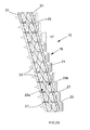
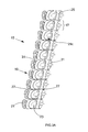
- FIGS 2 and 3 show opposite sides of a strip 15 of fastener assemblies 17 according to the invention.
- Each fastener assembly 17 comprises an elongate fastener 19 (e.g. a nail or pin), comprising a head 21 and a pointed shank 23, and a support collar 25 mounted on the fastener.
- the fastener 19 will normally be formed from metal (e.g. steel) and the support collar 25 will normally be formed (especially, moulded) from a polymeric material.
- the strip 15 of fastener assemblies 17 comprises a strip of support collars 25 arranged in a substantially straight line with each support collar joined to one or two neighbouring support collars, and with a respective elongate fastener 19 located in each support collar. Neighbouring support collars 15 are joined to each other by means of breakable webs 27. In fact, the strip of support collars 15, including the breakable webs 27, comprises a single moulded polymeric article.
- the fasteners 19 of the strip 15 are all substantially parallel to each other, but each fastener 19 and support collar 25 is longitudinally displaced with respect to its neighbour(s), so that the entire strip 15 of fastener assemblies 17 is inclined with respect to the longitudinal axes of the elongate fasteners and support collars. This is so that the strip 15 can fit into an inclined magazine 11 of a fastener-driving tool 1.
- Each support collar 25 of the strip 15 is shaped such that it has profiles on opposite sides of the fastener (and on opposite sides of the strip) that are asymmetric with respect to each other.
- one side of each support collar (and one side of each strip) has two recesses 29a and 29b, whereas the opposite side of each support collar (and the opposite side of each strip) has a single recess 29c.
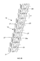
- the recesses have a staggered relationship (as most easily seen in figures 4 and 5 ) in which part of single recess 29c on one side of the fastener is situated between parts of the two recesses 29a and 29b on the opposite side of the fastener.
- All three recesses 29a, 29b and 29c are generally V-shaped in profile (see figures 4 and 5 ), but the profile area (or cross-sectional area) of the single recess 29c is approximately twice that of the profile area of each of recesses 29a and 29b, such that the combined profile area of the two recesses 29a and 29b is approximately the same as that of the single recess 29c.
- Each recess 29a, 29b and 29c is sufficiently deep that part of the shank 23 of the elongate fastener 19 is exposed by the recess.
- each support collar 25 includes a flange 31 at each end of the collar, and each flange is also inclined at substantially the same angle of inclination as that of the entire strip 15.
- each support collar 25 is shaped generally like the letter "M".
- This general shape (which is somewhat analogous to a concertina) can help to provide a degree of resilient compressibility ("springiness") in use between the fastener head 21 and a workpiece, when a fastener assembly 17 has been driven from the tool 1. Even if part of the support collar 25 splits as the fastener assembly is driven into a workpiece, often part of the support collar (e.g. one or two "V” shapes of the "M” shaped profile) will remain, thus providing additional resilient compressibility (compared to the resilient compressibility of a simple block of the material of the support collar).
- a passage 33 within a fastener magazine and/or part of a nose piece of the fastener-driving tool 1 is provided with asymmetric profiles on opposite sides (e.g. corresponding to the asymmetric profiles of the support collar 25), namely a pair of protruding ribs 35a and 35b on one side, and a single protruding rib 35c on the opposite side.
- asymmetric profiles on opposite sides e.g. corresponding to the asymmetric profiles of the support collar 25
- Each recess in the support collar 25 (and thus each line of recesses in the strip) is arranged to accommodate a respective protruding rib of the passage 33.
- the lack of symmetry on opposite sides of the fastener assemblies 17 thus requires the user to insert the fastener assemblies into the tool 1 in the correct orientation for the tool, and in this way it can lessen the likelihood of fastener assemblies jamming in the tool, etc. Additionally, the staggered arrangement of the cooperating ribs and recesses provides good guidance of the fastener assemblies in the passage 33, again lessening the chance of fastener assemblies jamming in the tool.
Landscapes
- Engineering & Computer Science (AREA)
- Mechanical Engineering (AREA)
- General Engineering & Computer Science (AREA)
- Portable Nailing Machines And Staplers (AREA)
- Connection Of Plates (AREA)
- Clamps And Clips (AREA)
Abstract
Description
- The present invention relates to supports and support collars for elongate fasteners such as nails, pins, screws and the like, and fastener assemblies comprising such supports and support collars mounted on elongate fasteners. The invention particularly relates to strips of such fastener assemblies, in which the support collars are joined together, thereby providing strips of collated fasteners. The invention also relates to fastener-driving tools for such fastener assembly strips.
- Many fastener-driving tools include a driver that is propelled rapidly against a fastener to drive a fastener from the tool into a workpiece. The driver may comprise a piston, or a ram (impact member), for example. The driver may be propelled in any of a variety of ways, including (but not limited to) pneumatically, by combustion, by means of a strap or chain, by means of a separate piston, or by means of one or more flywheels, for example.
- Fastener-driving (or firing) tools have for many years included magazines (i.e. holding and supply devices) for the fasteners that are driven/fired from the tools. There are various known types of such magazines, including magazines arranged to store and supply loose fasteners, magazines for coiled strips of fasteners, and magazines for straight or curved strips of fasteners.
- United States Patent No.
5,069,340 discloses a strip of collated elongate fasteners in which a carrier moulded from a polymeric material has a sleeve for each fastener. Each sleeve has an annular portion, and a breakable portion which breaks into two segments as the fastener gripped by the sleeve is driven from a fastener-driving tool. The breakable portion has a pair of similar, laterally opposed, outwardly opening, continuously curved concave recesses with open windows from which portions of the fastener emerges. In a fastener-driving tool, parallel ribs of a guiding device fit into such recesses, so as to guide the strip between such ribs. In use, the strip of collated fasteners is advanced incrementally towards a fastener-driving region, such that the leading fastener and its sleeve are driven from the tool into a workpiece. - United States Patent No.
3,438,487 discloses a carrier for holding a plurality of fasteners with their shanks in a spaced-apart parallel relation, comprising an elongate flexible strip. The strip comprises a web transversely spaced apart from the fastener shanks, and a plurality of slotted flanges along the upper and lower edges of the web extending substantially perpendicular to the web, for supporting the shank of each fastener. In this arrangement, when each fastener is driven from a fastener-driving tool, the fastener is separated from the carrier strip, and the carrier strip remains attached to the tool. - United States Patent No.
3,830,364 discloses a nail carrier for supporting and locating nails to be fed to a power-operated nail driving device. The carrier comprises a rigid plate having, on its top side, a first group of rigid studs arranged in two parallel spaced-apart rows and a second group of yielding studs disposed in one row parallel to the other two rows, and extending from the underside of the plate are reinforcing flanges. Two studs of the first group in conjunction with one stud of the second group provide a locating position for a nail, and this is repeated along the nail carrier. - The present invention seeks to provide improved fastener supports and support collars, fastener assemblies, strips of support collars and assemblies, and fastener-driving tools.
- In a first aspect, the present invention provides a fastener assembly, comprising an elongate fastener, and a support collar mounted on the fastener, the support collar shaped such that it has profiles on opposite sides of the fastener that are asymmetric with respect to each other.
- A second aspect of the invention provides a support collar for an elongate fastener, the support collar shaped such that it has profiles on opposite sides of a longitudinal axis of the collar that are asymmetric with respect to each other. In use, the support collar is mounted on (i.e. around) an elongate fastener such that the fastener extends along the longitudinal axis of the collar.
- The support collar (of the first or second aspect of the invention) preferably comprises a single part, but in some embodiments of the invention the support collar may comprise two or more separate parts which, at least when mounted on a fastener, combine to form the support collar. For example, the support collar may comprise two separate collar components which, at least when mounted on a fastener, combine to provide the asymmetric profiles.
- By the "profile" of a side of the support collar is meant the outline of that side of the support collar when viewed from a direction substantially perpendicular to that side, i.e. the outline of the side when viewed in profile.
- Preferably, the asymmetry in the collar profiles on opposite sides of the fastener (i.e. on opposite sides of the longitudinal axis of the collar) comprises a longitudinal asymmetry along at least part of the length of the elongate fastener (longitudinal axis). Preferably the maximum distances, of both opposite profiles, from the longitudinal axis of the collar are substantially equal.
- The profiles on two opposite sides of the fastener preferably each include at least one recess. The asymmetry preferably comprises an asymmetry in the recesses on the two opposite sides of the fastener.
- An advantage of the present invention is that the asymmetry in the profiles on opposite sides of the support collar (and thus, on opposite sides of the fastener) can help to prevent the fastener assemblies being inserted into, and/or driven from, a fastener-driving tool in an incorrect orientation. For example, a passage within a fastener magazine and/or part of a nose piece of a fastener-driving tool may be provided with corresponding asymmetric profiles arranged to guide the support collar(s) of the invention (e.g. towards an outlet passage for the fasteners), and with which the asymmetric profiles of the support collar(s) are arranged to fit. The lack of symmetry on opposite sides of the fastener assemblies can thus require the user to insert the fastener assemblies into the tool in the correct orientation for the tool, and in this way it can lessen the likelihood of fastener assemblies jamming in the tool, etc.
- Another possible advantage of the invention is that the asymmetry in the profiles can help to provide improved guidance of the fastener assemblies in a fastener-driving tool (e.g. in a magazine and/or in a nose piece). For example, in the fastener assembly arrangement disclosed in United States Patent No.
5,069,340 described above, the support collar has symmetric profiles on opposite sides of the fastener, with identically positioned and shaped single recesses on each side, each of which cooperates with a single respective protruding rib in a passage of a fastener-driving tool. Arrangements such as this, especially those in which there is a single identical recess on each side of the fastener assembly, can sometimes fail to prevent twisting of the fastener assemblies (e.g. by the recesses of the fastener assembly rotating about their respective protruding ribs), thereby resulting in them being jammed within the tool. In contrast, if fastener assemblies with asymmetric profiles are used, this enables the possibility of better guiding to prevent twisting. For example, if a fastener assembly is provided with two recesses on one side, and a single recess (or three recesses) on the opposite side, there may be less chance of the recesses of the fastener assembly rotating about their respective protruding ribs, and thus less chance of jamming. The provision of a single recess on one side, and two recesses on the opposite side, is a particularly simple and convenient way of achieving this, for example. - A further possible advantage of the invention concerns the performance of a fastener in use, after it has been driven from a fastening-driving tool. As explained in United States Patent No.
5,069,340 , it is often desirable for at least part of the support collar of a fastener assembly to be retained on the fastener after the fastener has been driven into a workpiece. This is advantageous because the presence of at least part of the support collar between (for example) the head of a nail or pin and the workpiece can avoid the occurrence of a gap between the head and the workpiece (thus providing a more secure attachment of a workpiece to a substrate). Additionally, any resilient compressibility provided by the support collar can prevent such a gap appearing or widening over time (e.g. due to vibration, etc.). A disadvantage of the type of symmetrical support collar disclosed inUS 5,069,340 is that the part of the support collar that remains attached to the fastener is an annular block of material, which has moderately low resilient compressibility. In contrast, with at least some asymmetric support collars of the present invention, it may be possible to provide additional resilient compressibility (i.e. "springiness") from the shape of the support collar. This will be explained further, below. - As mentioned above, the profiles on the two opposite sides of the fastener may each include at least one recess. The asymmetry may thus comprise an asymmetry in the number of recesses. For example, the support collar may have a single recess on one side of the fastener, and two or more recesses on the opposite side of the fastener, or the support collar may have two recesses on one side of the fastener, and three or more recesses on the opposite side of the fastener. Other numbers of recesses are possible.
- Additionally or alternatively, the asymmetry may comprise an asymmetry in the positions and/or shapes and/or sizes and/or orientations of the recesses. For example, recesses on opposite sides of the fastener may have a mutually off-set or staggered arrangement. In a preferred embodiment of the invention, the recesses alternate between the two opposite sides of the fastener, along part of the length of the fastener. For example, at least part of one recess on one side of the fastener may be situated between at least parts of two recesses on the opposite side of the fastener.
- Preferably, at least one recess is generally V-shaped in profile. Advantageously, each recess may be generally V-shaped, but other shapes are possible. If each recess is V-shaped (or some other basic shape), recesses on opposite sides of the fastener may nonetheless have different shapes (e.g. different V-shapes).
- Each recess in the sides of the support collar preferably is sufficiently deep that it exposes part of the elongate fastener extending through the support collar. However, in some embodiments of the invention, it is possible for one or more recesses not to expose part of the elongate fastener.
- A third aspect of the invention provides a fastener assembly, comprising an elongate fastener, and a support mounted on the fastener, the support shaped such that it has profiles on two opposite sides of the fastener that are asymmetric with respect to each other, each profile including at least one recess that is sufficiently deep that it exposes part of the elongate fastener to which the support is mounted. Preferably the support comprises a support collar.
- The support collar preferably includes an end surface at one or both opposite ends thereof, which substantially encircles part of the elongate fastener. Additionally or alternatively, the support collar may include a flange at one or both opposite ends thereof. Preferably, the flange is substantially annular and encircles part of the elongate fastener. Advantageously, the end surface or flange is not perpendicular to a longitudinal axis of the elongate fastener. For example, the end surface or flange may be inclined at substantially the same angle as an angle of inclination of an entire strip of fasteners or support collars (described below).
- A fourth aspect of the invention provides a fastener strip comprising a plurality of fastener assemblies according to the first aspect of the invention, in which each support collar is joined to one or two neighbouring support collars in a strip.
- A fifth aspect of the invention provides a strip of fastener support collars, comprising a plurality of support collars according to the second aspect of the invention, in which each support collar is joined to one or two neighbouring support collars.
- The strip of support collars (of the fourth or fifth aspects of the invention) preferably comprises a single part (e.g. moulded in one piece), but in some embodiments of the invention the strip of support collars may comprise two or more separate parts which, at least when mounted on the fasteners, combine to form the strip of support collars. For example, the strip of support collars may comprise two separate strips which, at least when mounted on a fastener, combine to provide the strip of support collars.
- Preferably, the asymmetric profiles are on opposite sides of the fastener strip or on opposite sides of the strip of fastener support collars. That is, the asymmetric profiles preferably are situated on sides of the support collars that form opposite sides of a strip (rather than on sides of the support collars that are situated adjacent to neighbouring collars in the strip). Preferably, in a fastener strip or support collar strip, the support collar profiles on one side of the strip are substantially identical to each other and preferably are arranged substantially in a straight line. The support collar profiles on the opposite side of the strip preferably are substantially identical to each other (but lacking symmetry with the first side of the strip) and preferably are arranged substantially in a straight line.
- A sixth aspect of the invention provides a fastener strip comprising a plurality of fastener assemblies according to the third aspect of the invention, in which each support is joined to one or two neighbouring supports in a strip. The strip of supports preferably comprises a single part (e.g. moulded in one piece), but in some embodiments of the invention the strip of supports may comprise two or more separate parts which, at least when mounted on the fasteners, combine to form the strip of supports.
- A seventh aspect of the invention provides a combination of a fastener-driving tool and a fastener assembly or strip, in which the fastener-driving tool has a fastener supply passage provided with profiles on opposite sides thereof that are asymmetric with respect to each other, and the fastener assembly or strip is arranged to fit in the supply passage. Preferably the fastener assembly or strip is a fastener assembly or strip according to the first, third, fourth or sixth aspect of the invention.
- Advantageously, the fastener/support collar strip may be substantially straight, or it may curve. The axes of the fasteners/support collars preferably lie in a plane, and in this plane the strip may be straight or curved, for example. Preferably, the axes are substantially parallel to each other, in which case the strip will normally be straight, but the axes may alternatively be non-parallel to each other, in which case the strip may be curved. The support collars may be arranged such that there is no longitudinal displacement between them (i.e. they are next to each other in a straight row), or each support collar may be longitudinally displaced with respect to its neighbour(s), e.g. such that the strip as a whole is inclined with respect to the longitudinal axes of the elongate fasteners and support collars.
- Preferred embodiments of the invention will now be described, by way of example, with reference to the accompanying drawings, of which:
-
Figure 1 shows a fastening driving tool according to the invention, with a magazine loaded with fastener assemblies according to the invention; -
Figure 2 ((a) and (b)) shows two views of one side of a strip of fastener assemblies according to the invention; -
Figure 3 ((a) and (b)) shows two views of the opposite side of the strip of fastener assemblies as shown inFigure 2 ; -
Figure 4 ((a) and (b)) shows opposite ends of the strip of fastener assemblies as shown infigures 2 and3 , and view (b) shows the fastener strip located in a fastener supply passage of a fastener-driving tool according to the invention; and -
Figure 5 shows a further view of the strip of fastener assemblies as shown infigures 2 ,3 and4 . -
Figure 1 shows a fastener-driving tool 1, comprising amain body 3 housing a fastener-driving mechanism, ahandle 5, a battery 7, a nose piece 9, and afastener magazine 11. Thefastener magazine 11 is loaded with one ormore strips 15 of fastener assemblies according to the invention (shown schematically). The magazine, which is inclined with respect to the nose piece 9 to provide good accessibility to a workpiece, holds the fastener assemblies and supplies them to the nose piece by means of a spring-loadedpusher 13, as known in the art. -
Figures 2 and3 (views (a) and (b)) show opposite sides of astrip 15 offastener assemblies 17 according to the invention. Eachfastener assembly 17 comprises an elongate fastener 19 (e.g. a nail or pin), comprising ahead 21 and a pointedshank 23, and asupport collar 25 mounted on the fastener. Thefastener 19 will normally be formed from metal (e.g. steel) and thesupport collar 25 will normally be formed (especially, moulded) from a polymeric material. - The
strip 15 offastener assemblies 17 comprises a strip ofsupport collars 25 arranged in a substantially straight line with each support collar joined to one or two neighbouring support collars, and with a respectiveelongate fastener 19 located in each support collar. Neighbouringsupport collars 15 are joined to each other by means ofbreakable webs 27. In fact, the strip ofsupport collars 15, including thebreakable webs 27, comprises a single moulded polymeric article. In use (as is conventional), when anend fastener 19 of thestrip 15 is driven from a tool (such as the tool 1 shown inFigure 1 ) by a ram or other impact device, thesupport collar 25 located on the fastener is forcibly disconnected from its neighbouring support collar, and thefastener 19 together with itssupport collar 25 is driven from the tool into a workpiece. - The
fasteners 19 of thestrip 15 are all substantially parallel to each other, but eachfastener 19 andsupport collar 25 is longitudinally displaced with respect to its neighbour(s), so that theentire strip 15 offastener assemblies 17 is inclined with respect to the longitudinal axes of the elongate fasteners and support collars. This is so that thestrip 15 can fit into aninclined magazine 11 of a fastener-driving tool 1. - Each
support collar 25 of thestrip 15 is shaped such that it has profiles on opposite sides of the fastener (and on opposite sides of the strip) that are asymmetric with respect to each other. In particular, one side of each support collar (and one side of each strip) has tworecesses single recess 29c. The recesses have a staggered relationship (as most easily seen infigures 4 and5 ) in which part ofsingle recess 29c on one side of the fastener is situated between parts of the tworecesses recesses figures 4 and5 ), but the profile area (or cross-sectional area) of thesingle recess 29c is approximately twice that of the profile area of each ofrecesses recesses single recess 29c. Eachrecess shank 23 of theelongate fastener 19 is exposed by the recess. All of the recesses are inclined at substantially the same angle of inclination (approximately 15 degrees, as drawn) as that of theentire strip 15, and each recess is in line with the corresponding recesses of the other support collars in the strip. Additionally, eachsupport collar 25 includes aflange 31 at each end of the collar, and each flange is also inclined at substantially the same angle of inclination as that of theentire strip 15. - In profile, each
support collar 25 is shaped generally like the letter "M". This general shape (which is somewhat analogous to a concertina) can help to provide a degree of resilient compressibility ("springiness") in use between thefastener head 21 and a workpiece, when afastener assembly 17 has been driven from the tool 1. Even if part of thesupport collar 25 splits as the fastener assembly is driven into a workpiece, often part of the support collar (e.g. one or two "V" shapes of the "M" shaped profile) will remain, thus providing additional resilient compressibility (compared to the resilient compressibility of a simple block of the material of the support collar). - As shown in
Figure 4(b) , apassage 33 within a fastener magazine and/or part of a nose piece of the fastener-driving tool 1 is provided with asymmetric profiles on opposite sides (e.g. corresponding to the asymmetric profiles of the support collar 25), namely a pair of protrudingribs protruding rib 35c on the opposite side. Each recess in the support collar 25 (and thus each line of recesses in the strip) is arranged to accommodate a respective protruding rib of thepassage 33. The lack of symmetry on opposite sides of thefastener assemblies 17 thus requires the user to insert the fastener assemblies into the tool 1 in the correct orientation for the tool, and in this way it can lessen the likelihood of fastener assemblies jamming in the tool, etc. Additionally, the staggered arrangement of the cooperating ribs and recesses provides good guidance of the fastener assemblies in thepassage 33, again lessening the chance of fastener assemblies jamming in the tool. - It will be understood that the above description and the drawings are of particular examples of the invention, but that other examples of the invention are included in the scope of the claims.
Claims (19)
- A fastener assembly, comprising an elongate fastener, and a support collar mounted on the fastener, the support collar shaped such that it has profiles on opposite sides of the fastener that are asymmetric with respect to each other.
- A fastener assembly according to claim 1, in which the asymmetry comprises a longitudinal asymmetry along at least part of the length of the elongate fastener, on opposite sides of the fastener.
- A fastener assembly according to claim 1 or claim 2, in which the profiles on two opposite sides of the fastener each include at least one recess.
- A fastener assembly according to claim 3, in which the asymmetry comprises an asymmetry in the recesses on the two opposite sides of the fastener.
- A fastener assembly according to claim 4, in which the asymmetry comprises an asymmetry in the number of recesses.
- A fastener assembly according to claim 5, in which the support collar has a single recess on one side of the fastener, and two or more recesses on the opposite side of the fastener.
- A fastener assembly according to claim 5, in which the support collar has two recesses on one side of the fastener, and three or more recesses on the opposite side of the fastener
- A fastener assembly according to any one of claims 4 to 7, in which the asymmetry comprises an asymmetry in the positions of the recesses.
- A fastener assembly according to any one of claims 4 to 8, in which the asymmetry comprises an asymmetry in the shapes of the recesses.
- A fastener assembly according to any one of claims 4 to 9, in which the asymmetry comprises an asymmetry in the sizes of the recesses.
- A fastener assembly according to any one of claims 4 to 10, in which the asymmetry comprises an asymmetry in the orientations of the recesses.
- A fastener assembly according to any one of claims 3 to 11, in which the recesses alternate between the two opposite sides of the fastener, along part of the length of the fastener.
- A fastener assembly according to any one of claims 3 to 12, in which at least part of one recess on one side of the fastener is situated between at least parts of two recesses on the opposite side of the fastener.
- A fastener assembly according to any one of claims 3 to 13, in which at least one recess is generally V-shaped in profile.
- A fastener assembly according to any preceding claim, in which the collar includes an end surface at one or both opposite ends thereof, which substantially encircles part of the elongate fastener.
- A fastener strip, comprising a plurality of fastener assemblies according to any preceding claim, in which each support collar is joined to one or two neighbouring support collars in a strip.
- A fastener strip according to claim 16, in which the asymmetric profiles are on opposite sides of the strip.
- A combination of a fastener-driving tool and a fastener assembly or strip, in which the fastener-driving tool has a fastener supply passage provided with profiles on opposite sides thereof that are asymmetric with respect to each other, and the fastener assembly or strip is arranged to fit in the supply passage.
- A combination according to claim 18, in which the fastener assembly or strip is a fastener assembly or strip according to any one of claims 1 to 17.
Priority Applications (1)
| Application Number | Priority Date | Filing Date | Title |
|---|---|---|---|
| US12/907,288 US8517238B2 (en) | 2009-09-04 | 2010-10-19 | Fastener assembly |
Applications Claiming Priority (1)
| Application Number | Priority Date | Filing Date | Title |
|---|---|---|---|
| GBGB0915371.9A GB0915371D0 (en) | 2009-09-04 | 2009-09-04 | Fastener assembly |
Publications (3)
| Publication Number | Publication Date |
|---|---|
| EP2295821A2 true EP2295821A2 (en) | 2011-03-16 |
| EP2295821A3 EP2295821A3 (en) | 2013-04-03 |
| EP2295821B1 EP2295821B1 (en) | 2019-05-22 |
Family
ID=41203124
Family Applications (1)
| Application Number | Title | Priority Date | Filing Date |
|---|---|---|---|
| EP10174225.2A Active EP2295821B1 (en) | 2009-09-04 | 2010-08-26 | Fastener assembly |
Country Status (6)
| Country | Link |
|---|---|
| US (1) | US8517238B2 (en) |
| EP (1) | EP2295821B1 (en) |
| JP (1) | JP5722575B2 (en) |
| CN (1) | CN102011777B (en) |
| ES (1) | ES2731341T3 (en) |
| GB (1) | GB0915371D0 (en) |
Cited By (3)
| Publication number | Priority date | Publication date | Assignee | Title |
|---|---|---|---|---|
| WO2015197848A1 (en) * | 2014-06-26 | 2015-12-30 | Finsecur | Support part for supporting a device, smoke detector and nailer extender for nailing such a support part |
| EP3338953A1 (en) * | 2016-12-22 | 2018-06-27 | Muro Corporation | Screw rope for use in successive screw clamping machine |
| EP3674569A1 (en) * | 2018-12-27 | 2020-07-01 | Max Co., Ltd. | Connection fastener |
Families Citing this family (25)
| Publication number | Priority date | Publication date | Assignee | Title |
|---|---|---|---|---|
| US8382414B2 (en) * | 2010-01-11 | 2013-02-26 | National Nail Corp. | Threaded fastener and related method of installation |
| US9120214B2 (en) | 2010-01-13 | 2015-09-01 | National Nail Corp. | Fastener, installation tool and related method of use |
| US8955210B2 (en) | 2010-01-13 | 2015-02-17 | National Nail Corp. | Fastener, installation tool and related method of use |
| US9802300B2 (en) | 2010-01-13 | 2017-10-31 | National Nail Corp. | Fastener, installation tool and related method of use |
| US9144896B2 (en) | 2010-01-13 | 2015-09-29 | National Nail Corp. | Fastener, installation tool and related method of use |
| US8672204B2 (en) | 2010-01-13 | 2014-03-18 | National Nail Corp. | Fastener, installation tool and related method of use |
| JP5213979B2 (en) | 2011-03-17 | 2013-06-19 | 日本特殊陶業株式会社 | Fine particle sensor and its mounting structure |
| USD704018S1 (en) | 2012-01-04 | 2014-05-06 | National Nail Corp. | Fastener installation tool |
| DE102014005105A1 (en) * | 2014-04-08 | 2015-10-08 | Adunox Gmbh | Magazine tape and magazine feed for such a magazine tape |
| FR3064035B1 (en) * | 2017-03-16 | 2019-04-19 | Sogefi Air & Cooling | REMOVABLE SLEEVE FOR HOLDING AND ATTACHING SCREWS |
| USD924044S1 (en) | 2019-11-20 | 2021-07-06 | National Nail Corp. | Fastener positioning device |
| US11261893B2 (en) | 2017-08-15 | 2022-03-01 | National Nail Corp. | Hidden fastener unit and related method of use |
| US11149445B2 (en) | 2017-08-15 | 2021-10-19 | National Nail Corp. | Hidden fastener unit and related method of use |
| US20210277668A1 (en) | 2017-08-15 | 2021-09-09 | National Nail Corp. | Hidden fastener unit and related method of use |
| USD1019365S1 (en) | 2023-05-31 | 2024-03-26 | National Nail Corp. | Fastener positioning device |
| US11111679B2 (en) | 2017-08-15 | 2021-09-07 | National Nail Corp. | Hidden fastener unit and related method of use |
| USD945870S1 (en) | 2020-11-17 | 2022-03-15 | National Nail Corp. | Fastener positioning device |
| US11898357B2 (en) | 2017-08-15 | 2024-02-13 | National Nail Corp. | Hidden fastener unit and related method of use |
| EP3501749A1 (en) * | 2017-12-20 | 2019-06-26 | HILTI Aktiengesellschaft | Fixing element strips |
| USD842086S1 (en) | 2018-02-26 | 2019-03-05 | National Nail Corp. | Screw |
| CN112757207B (en) * | 2021-01-27 | 2022-08-19 | 河南科技大学 | Chain type automatic screw feeding device and screw gun |
| US11731252B2 (en) | 2021-01-29 | 2023-08-22 | National Nail Corp. | Screw guide and related method of use |
| TWI767558B (en) * | 2021-02-09 | 2022-06-11 | 温芫鋐 | Thread tail sleeve gun |
| US11938596B1 (en) | 2023-01-26 | 2024-03-26 | National Nail Corp. | Fastener installation tool and related method of use |
| USD1022684S1 (en) | 2023-02-23 | 2024-04-16 | National Nail Corp. | Fastener positioning device |
Citations (3)
| Publication number | Priority date | Publication date | Assignee | Title |
|---|---|---|---|---|
| US3438487A (en) | 1967-05-10 | 1969-04-15 | Fastener Corp | Carrier for holding a plurality of fasteners |
| US3830364A (en) | 1971-07-14 | 1974-08-20 | Cunneba Bruks Ab | Carrier for nails for nail driving device |
| US5069340A (en) | 1991-03-05 | 1991-12-03 | Illinois Tool Works Inc. | Strip of collated fasteners for fastener-driving tool |
Family Cites Families (34)
| Publication number | Priority date | Publication date | Assignee | Title |
|---|---|---|---|---|
| US2525637A (en) * | 1948-10-01 | 1950-10-10 | William A Bell | Nailing machine |
| US3891087A (en) * | 1972-01-13 | 1975-06-24 | Textron Inc | Nail package improvements for interconnecting the trailing nail of one nail package with the leading nail of another nail package |
| US4383608A (en) * | 1973-08-10 | 1983-05-17 | Duo-Fast Corporation | Fastener strip and strip feeding apparatus |
| US3915367A (en) * | 1973-08-10 | 1975-10-28 | Duo Fast Corp | Fastener strip and strip feeding apparatus |
| US3858782A (en) * | 1973-10-19 | 1975-01-07 | Omark Industries Inc | Pneumatic fastener driving tool |
| US3930297A (en) * | 1973-11-05 | 1976-01-06 | Duo-Fast Corporation | Fastener feed apparatus and method |
| US3910324A (en) * | 1974-04-29 | 1975-10-07 | Duo Fast Corp | Rotary entry fastener driving tool |
| US3885669A (en) * | 1974-04-29 | 1975-05-27 | Duo Fast Corp | Rotary entry fastener carrier and strip |
| US4251017A (en) * | 1979-04-11 | 1981-02-17 | Duo-Fast Corporation | Fastener driving tool |
| US4367837A (en) * | 1980-04-25 | 1983-01-11 | Manino Anthony P | Tape magazine feed apparatus for head driven fasteners |
| JPS58175214U (en) * | 1982-05-19 | 1983-11-24 | 株式会社大築 | peg |
| US4606455A (en) * | 1984-08-17 | 1986-08-19 | Duo-Fast Corporation | Collated fastener strip |
| US4581964A (en) * | 1985-02-22 | 1986-04-15 | Max Co. Ltd. | Fastener driving tool with improved magazine and feed mechanism |
| US4913611A (en) * | 1988-12-23 | 1990-04-03 | Leistner H E | Nailing strip |
| JPH0721923Y2 (en) * | 1989-02-16 | 1995-05-17 | マックス株式会社 | Nail connecting band for nailer |
| EP0438663B1 (en) * | 1990-01-23 | 1994-08-31 | WAKAI & CO., LTD. | Tape for holding nails |
| US5443345A (en) * | 1994-06-20 | 1995-08-22 | Illinois Tool Works Inc. | Fastener-sleeve assembly and strip of collated fasteners |
| US5615819A (en) * | 1995-10-03 | 1997-04-01 | Hou; Chang Feng-Mei | Nail magazine structure of a power nailer |
| US6098801A (en) * | 1998-09-03 | 2000-08-08 | Senco Products, Inc. | Collating strip and strip assembly for use with a manual welding tool |
| CN1117222C (en) * | 1998-10-07 | 2003-08-06 | 伊利诺伊工具公司 | Fastener assembly with cross end lengthening part |
| US6024268A (en) * | 1999-03-08 | 2000-02-15 | Basso Industry Corp. | Nail engaging device for a power nailer |
| DE19957109B4 (en) * | 1999-11-26 | 2008-05-29 | Hilti Ag | Nail strip with nails |
| US6823990B2 (en) * | 2000-08-21 | 2004-11-30 | Power Products Iii, Llc | Nail holder strip |
| US6494322B1 (en) * | 2000-10-31 | 2002-12-17 | G. Lyle Habermehl | Arrow head screwstrip |
| AU2002338113C1 (en) * | 2001-09-28 | 2008-07-10 | Max Kabushiki Kaisha | Connecting fastener |
| US6814231B2 (en) * | 2002-01-23 | 2004-11-09 | Illinois Tool Works Inc. | Strip of collated fasteners for fastener-driving tool |
| US20040118720A1 (en) * | 2002-12-18 | 2004-06-24 | Powers Fasteners, Inc. | Fastener carrier assembly and method of use |
| US7021462B2 (en) * | 2002-12-18 | 2006-04-04 | Powers Fasteners, Inc. | Fastener carrier assembly and method of use |
| US6779959B1 (en) * | 2003-04-21 | 2004-08-24 | Testo Industry Corp. | Belt of nails for nailers |
| CN201015860Y (en) * | 2004-04-02 | 2008-02-06 | 布莱克和戴克公司 | Power tool with a driver |
| US7735577B2 (en) * | 2005-09-20 | 2010-06-15 | Power Products Iii, Llc | Carrier strip system and method for different diameter fasteners |
| JP2009041731A (en) * | 2007-08-10 | 2009-02-26 | Opt Engineering Co Ltd | Rivet holding body |
| USD605016S1 (en) * | 2007-08-17 | 2009-12-01 | Simpson Strong-Tie Company, Inc. | Collation strip |
| JP5205921B2 (en) * | 2007-11-06 | 2013-06-05 | マックス株式会社 | Connecting fastener |
-
2009
- 2009-09-04 GB GBGB0915371.9A patent/GB0915371D0/en not_active Ceased
-
2010
- 2010-08-26 EP EP10174225.2A patent/EP2295821B1/en active Active
- 2010-08-26 ES ES10174225T patent/ES2731341T3/en active Active
- 2010-09-03 CN CN201010275262.0A patent/CN102011777B/en not_active Expired - Fee Related
- 2010-09-03 JP JP2010198243A patent/JP5722575B2/en active Active
- 2010-10-19 US US12/907,288 patent/US8517238B2/en active Active
Patent Citations (3)
| Publication number | Priority date | Publication date | Assignee | Title |
|---|---|---|---|---|
| US3438487A (en) | 1967-05-10 | 1969-04-15 | Fastener Corp | Carrier for holding a plurality of fasteners |
| US3830364A (en) | 1971-07-14 | 1974-08-20 | Cunneba Bruks Ab | Carrier for nails for nail driving device |
| US5069340A (en) | 1991-03-05 | 1991-12-03 | Illinois Tool Works Inc. | Strip of collated fasteners for fastener-driving tool |
Cited By (7)
| Publication number | Priority date | Publication date | Assignee | Title |
|---|---|---|---|---|
| WO2015197848A1 (en) * | 2014-06-26 | 2015-12-30 | Finsecur | Support part for supporting a device, smoke detector and nailer extender for nailing such a support part |
| FR3022970A1 (en) * | 2014-06-26 | 2016-01-01 | Finsecur | SUPPORT PART FOR SUPPORTING A DEVICE, SMOKE DETECTOR AND NAIL EXTENSION FOR NOWING SUCH A SUPPORT PART |
| EP3338953A1 (en) * | 2016-12-22 | 2018-06-27 | Muro Corporation | Screw rope for use in successive screw clamping machine |
| US10737372B2 (en) | 2016-12-22 | 2020-08-11 | Muro Corporation | Successive screw tightening machine and screw rope for use therewith |
| EP3674569A1 (en) * | 2018-12-27 | 2020-07-01 | Max Co., Ltd. | Connection fastener |
| CN111412209A (en) * | 2018-12-27 | 2020-07-14 | 美克司株式会社 | Joining fastener |
| US11624391B2 (en) | 2018-12-27 | 2023-04-11 | Max Co., Ltd. | Connection fastener |
Also Published As
| Publication number | Publication date |
|---|---|
| JP2011058627A (en) | 2011-03-24 |
| GB0915371D0 (en) | 2009-10-07 |
| CN102011777B (en) | 2016-03-09 |
| EP2295821B1 (en) | 2019-05-22 |
| US20120048909A1 (en) | 2012-03-01 |
| CN102011777A (en) | 2011-04-13 |
| EP2295821A3 (en) | 2013-04-03 |
| US8517238B2 (en) | 2013-08-27 |
| ES2731341T3 (en) | 2019-11-15 |
| JP5722575B2 (en) | 2015-05-20 |
Similar Documents
| Publication | Publication Date | Title |
|---|---|---|
| EP2295821B1 (en) | Fastener assembly | |
| JP5175091B2 (en) | Guide device for fixing device | |
| US5813588A (en) | Magazine assembly for fastener driving tools | |
| US5069340A (en) | Strip of collated fasteners for fastener-driving tool | |
| US20180029211A1 (en) | Staple tool | |
| US9573260B2 (en) | Fastening device for driving double-headed fasteners | |
| EP3396180B1 (en) | Fencing staple | |
| US20140294535A1 (en) | Fastener assembly | |
| EP1333185A1 (en) | Strip of collated fasteners for fastener-driving tool | |
| EP1415767B1 (en) | Magazine rail system for fastener-driving tool | |
| CA1086269A (en) | Fastener assembly | |
| EP3168008B1 (en) | Powered nail driver with a nail placement assembly | |
| US11746815B2 (en) | Staple and staple collation | |
| US8985426B2 (en) | Fastener driver assembly | |
| US8430290B2 (en) | System and method for driving a fastener | |
| EP3401059B1 (en) | Staple tool | |
| US20040182908A1 (en) | Power tool for metal piercing fasteners | |
| JP2006153241A (en) | Striking-type fastener, connection fastener and structure | |
| TW346431B (en) | Magazine assembly for fastener driving tools |
Legal Events
| Date | Code | Title | Description |
|---|---|---|---|
| PUAI | Public reference made under article 153(3) epc to a published international application that has entered the european phase |
Free format text: ORIGINAL CODE: 0009012 |
|
| AK | Designated contracting states |
Kind code of ref document: A2 Designated state(s): AL AT BE BG CH CY CZ DE DK EE ES FI FR GB GR HR HU IE IS IT LI LT LU LV MC MK MT NL NO PL PT RO SE SI SK SM TR |
|
| AX | Request for extension of the european patent |
Extension state: BA ME RS |
|
| PUAL | Search report despatched |
Free format text: ORIGINAL CODE: 0009013 |
|
| AK | Designated contracting states |
Kind code of ref document: A3 Designated state(s): AL AT BE BG CH CY CZ DE DK EE ES FI FR GB GR HR HU IE IS IT LI LT LU LV MC MK MT NL NO PL PT RO SE SI SK SM TR |
|
| AX | Request for extension of the european patent |
Extension state: BA ME RS |
|
| RIC1 | Information provided on ipc code assigned before grant |
Ipc: F16B 15/08 20060101ALI20130227BHEP Ipc: B25B 23/04 20060101ALI20130227BHEP Ipc: F16B 43/00 20060101ALI20130227BHEP Ipc: B25B 23/06 20060101ALI20130227BHEP Ipc: F16B 27/00 20060101AFI20130227BHEP |
|
| 17P | Request for examination filed |
Effective date: 20131003 |
|
| RBV | Designated contracting states (corrected) |
Designated state(s): AL AT BE BG CH CY CZ DE DK EE ES FI FR GB GR HR HU IE IS IT LI LT LU LV MC MK MT NL NO PL PT RO SE SI SK SM TR |
|
| 17Q | First examination report despatched |
Effective date: 20131205 |
|
| STAA | Information on the status of an ep patent application or granted ep patent |
Free format text: STATUS: EXAMINATION IS IN PROGRESS |
|
| GRAP | Despatch of communication of intention to grant a patent |
Free format text: ORIGINAL CODE: EPIDOSNIGR1 |
|
| STAA | Information on the status of an ep patent application or granted ep patent |
Free format text: STATUS: GRANT OF PATENT IS INTENDED |
|
| INTG | Intention to grant announced |
Effective date: 20190116 |
|
| GRAS | Grant fee paid |
Free format text: ORIGINAL CODE: EPIDOSNIGR3 |
|
| GRAA | (expected) grant |
Free format text: ORIGINAL CODE: 0009210 |
|
| STAA | Information on the status of an ep patent application or granted ep patent |
Free format text: STATUS: THE PATENT HAS BEEN GRANTED |
|
| AK | Designated contracting states |
Kind code of ref document: B1 Designated state(s): AL AT BE BG CH CY CZ DE DK EE ES FI FR GB GR HR HU IE IS IT LI LT LU LV MC MK MT NL NO PL PT RO SE SI SK SM TR |
|
| RAP1 | Party data changed (applicant data changed or rights of an application transferred) |
Owner name: BLACK & DECKER INC. |
|
| REG | Reference to a national code |
Ref country code: GB Ref legal event code: FG4D |
|
| REG | Reference to a national code |
Ref country code: CH Ref legal event code: EP |
|
| REG | Reference to a national code |
Ref country code: IE Ref legal event code: FG4D |
|
| REG | Reference to a national code |
Ref country code: DE Ref legal event code: R096 Ref document number: 602010059014 Country of ref document: DE |
|
| REG | Reference to a national code |
Ref country code: AT Ref legal event code: REF Ref document number: 1136468 Country of ref document: AT Kind code of ref document: T Effective date: 20190615 |
|
| REG | Reference to a national code |
Ref country code: SE Ref legal event code: TRGR |
|
| REG | Reference to a national code |
Ref country code: NL Ref legal event code: MP Effective date: 20190522 |
|
| REG | Reference to a national code |
Ref country code: LT Ref legal event code: MG4D |
|
| PG25 | Lapsed in a contracting state [announced via postgrant information from national office to epo] |
Ref country code: NO Free format text: LAPSE BECAUSE OF FAILURE TO SUBMIT A TRANSLATION OF THE DESCRIPTION OR TO PAY THE FEE WITHIN THE PRESCRIBED TIME-LIMIT Effective date: 20190822 Ref country code: FI Free format text: LAPSE BECAUSE OF FAILURE TO SUBMIT A TRANSLATION OF THE DESCRIPTION OR TO PAY THE FEE WITHIN THE PRESCRIBED TIME-LIMIT Effective date: 20190522 Ref country code: NL Free format text: LAPSE BECAUSE OF FAILURE TO SUBMIT A TRANSLATION OF THE DESCRIPTION OR TO PAY THE FEE WITHIN THE PRESCRIBED TIME-LIMIT Effective date: 20190522 Ref country code: PT Free format text: LAPSE BECAUSE OF FAILURE TO SUBMIT A TRANSLATION OF THE DESCRIPTION OR TO PAY THE FEE WITHIN THE PRESCRIBED TIME-LIMIT Effective date: 20190922 Ref country code: AL Free format text: LAPSE BECAUSE OF FAILURE TO SUBMIT A TRANSLATION OF THE DESCRIPTION OR TO PAY THE FEE WITHIN THE PRESCRIBED TIME-LIMIT Effective date: 20190522 Ref country code: LT Free format text: LAPSE BECAUSE OF FAILURE TO SUBMIT A TRANSLATION OF THE DESCRIPTION OR TO PAY THE FEE WITHIN THE PRESCRIBED TIME-LIMIT Effective date: 20190522 Ref country code: HR Free format text: LAPSE BECAUSE OF FAILURE TO SUBMIT A TRANSLATION OF THE DESCRIPTION OR TO PAY THE FEE WITHIN THE PRESCRIBED TIME-LIMIT Effective date: 20190522 |
|
| PGFP | Annual fee paid to national office [announced via postgrant information from national office to epo] |
Ref country code: SE Payment date: 20190813 Year of fee payment: 10 Ref country code: ES Payment date: 20190902 Year of fee payment: 10 Ref country code: FR Payment date: 20190711 Year of fee payment: 10 |
|
| PG25 | Lapsed in a contracting state [announced via postgrant information from national office to epo] |
Ref country code: GR Free format text: LAPSE BECAUSE OF FAILURE TO SUBMIT A TRANSLATION OF THE DESCRIPTION OR TO PAY THE FEE WITHIN THE PRESCRIBED TIME-LIMIT Effective date: 20190823 Ref country code: BG Free format text: LAPSE BECAUSE OF FAILURE TO SUBMIT A TRANSLATION OF THE DESCRIPTION OR TO PAY THE FEE WITHIN THE PRESCRIBED TIME-LIMIT Effective date: 20190822 Ref country code: LV Free format text: LAPSE BECAUSE OF FAILURE TO SUBMIT A TRANSLATION OF THE DESCRIPTION OR TO PAY THE FEE WITHIN THE PRESCRIBED TIME-LIMIT Effective date: 20190522 |
|
| REG | Reference to a national code |
Ref country code: AT Ref legal event code: MK05 Ref document number: 1136468 Country of ref document: AT Kind code of ref document: T Effective date: 20190522 |
|
| PG25 | Lapsed in a contracting state [announced via postgrant information from national office to epo] |
Ref country code: CZ Free format text: LAPSE BECAUSE OF FAILURE TO SUBMIT A TRANSLATION OF THE DESCRIPTION OR TO PAY THE FEE WITHIN THE PRESCRIBED TIME-LIMIT Effective date: 20190522 Ref country code: RO Free format text: LAPSE BECAUSE OF FAILURE TO SUBMIT A TRANSLATION OF THE DESCRIPTION OR TO PAY THE FEE WITHIN THE PRESCRIBED TIME-LIMIT Effective date: 20190522 Ref country code: AT Free format text: LAPSE BECAUSE OF FAILURE TO SUBMIT A TRANSLATION OF THE DESCRIPTION OR TO PAY THE FEE WITHIN THE PRESCRIBED TIME-LIMIT Effective date: 20190522 Ref country code: EE Free format text: LAPSE BECAUSE OF FAILURE TO SUBMIT A TRANSLATION OF THE DESCRIPTION OR TO PAY THE FEE WITHIN THE PRESCRIBED TIME-LIMIT Effective date: 20190522 Ref country code: DK Free format text: LAPSE BECAUSE OF FAILURE TO SUBMIT A TRANSLATION OF THE DESCRIPTION OR TO PAY THE FEE WITHIN THE PRESCRIBED TIME-LIMIT Effective date: 20190522 Ref country code: SK Free format text: LAPSE BECAUSE OF FAILURE TO SUBMIT A TRANSLATION OF THE DESCRIPTION OR TO PAY THE FEE WITHIN THE PRESCRIBED TIME-LIMIT Effective date: 20190522 |
|
| REG | Reference to a national code |
Ref country code: DE Ref legal event code: R097 Ref document number: 602010059014 Country of ref document: DE |
|
| PG25 | Lapsed in a contracting state [announced via postgrant information from national office to epo] |
Ref country code: IT Free format text: LAPSE BECAUSE OF FAILURE TO SUBMIT A TRANSLATION OF THE DESCRIPTION OR TO PAY THE FEE WITHIN THE PRESCRIBED TIME-LIMIT Effective date: 20190522 Ref country code: SM Free format text: LAPSE BECAUSE OF FAILURE TO SUBMIT A TRANSLATION OF THE DESCRIPTION OR TO PAY THE FEE WITHIN THE PRESCRIBED TIME-LIMIT Effective date: 20190522 |
|
| PLBE | No opposition filed within time limit |
Free format text: ORIGINAL CODE: 0009261 |
|
| STAA | Information on the status of an ep patent application or granted ep patent |
Free format text: STATUS: NO OPPOSITION FILED WITHIN TIME LIMIT |
|
| PG25 | Lapsed in a contracting state [announced via postgrant information from national office to epo] |
Ref country code: TR Free format text: LAPSE BECAUSE OF FAILURE TO SUBMIT A TRANSLATION OF THE DESCRIPTION OR TO PAY THE FEE WITHIN THE PRESCRIBED TIME-LIMIT Effective date: 20190522 |
|
| 26N | No opposition filed |
Effective date: 20200225 |
|
| PG25 | Lapsed in a contracting state [announced via postgrant information from national office to epo] |
Ref country code: PL Free format text: LAPSE BECAUSE OF FAILURE TO SUBMIT A TRANSLATION OF THE DESCRIPTION OR TO PAY THE FEE WITHIN THE PRESCRIBED TIME-LIMIT Effective date: 20190522 |
|
| PG25 | Lapsed in a contracting state [announced via postgrant information from national office to epo] |
Ref country code: SI Free format text: LAPSE BECAUSE OF FAILURE TO SUBMIT A TRANSLATION OF THE DESCRIPTION OR TO PAY THE FEE WITHIN THE PRESCRIBED TIME-LIMIT Effective date: 20190522 Ref country code: MC Free format text: LAPSE BECAUSE OF FAILURE TO SUBMIT A TRANSLATION OF THE DESCRIPTION OR TO PAY THE FEE WITHIN THE PRESCRIBED TIME-LIMIT Effective date: 20190522 Ref country code: LU Free format text: LAPSE BECAUSE OF NON-PAYMENT OF DUE FEES Effective date: 20190826 Ref country code: CH Free format text: LAPSE BECAUSE OF NON-PAYMENT OF DUE FEES Effective date: 20190831 Ref country code: LI Free format text: LAPSE BECAUSE OF NON-PAYMENT OF DUE FEES Effective date: 20190831 |
|
| REG | Reference to a national code |
Ref country code: BE Ref legal event code: MM Effective date: 20190831 |
|
| PG25 | Lapsed in a contracting state [announced via postgrant information from national office to epo] |
Ref country code: IE Free format text: LAPSE BECAUSE OF NON-PAYMENT OF DUE FEES Effective date: 20190826 |
|
| PG25 | Lapsed in a contracting state [announced via postgrant information from national office to epo] |
Ref country code: BE Free format text: LAPSE BECAUSE OF NON-PAYMENT OF DUE FEES Effective date: 20190831 |
|
| REG | Reference to a national code |
Ref country code: SE Ref legal event code: EUG |
|
| PG25 | Lapsed in a contracting state [announced via postgrant information from national office to epo] |
Ref country code: CY Free format text: LAPSE BECAUSE OF FAILURE TO SUBMIT A TRANSLATION OF THE DESCRIPTION OR TO PAY THE FEE WITHIN THE PRESCRIBED TIME-LIMIT Effective date: 20190522 Ref country code: SE Free format text: LAPSE BECAUSE OF NON-PAYMENT OF DUE FEES Effective date: 20200827 |
|
| PG25 | Lapsed in a contracting state [announced via postgrant information from national office to epo] |
Ref country code: IS Free format text: LAPSE BECAUSE OF FAILURE TO SUBMIT A TRANSLATION OF THE DESCRIPTION OR TO PAY THE FEE WITHIN THE PRESCRIBED TIME-LIMIT Effective date: 20190922 |
|
| PG25 | Lapsed in a contracting state [announced via postgrant information from national office to epo] |
Ref country code: MT Free format text: LAPSE BECAUSE OF FAILURE TO SUBMIT A TRANSLATION OF THE DESCRIPTION OR TO PAY THE FEE WITHIN THE PRESCRIBED TIME-LIMIT Effective date: 20190522 Ref country code: HU Free format text: LAPSE BECAUSE OF FAILURE TO SUBMIT A TRANSLATION OF THE DESCRIPTION OR TO PAY THE FEE WITHIN THE PRESCRIBED TIME-LIMIT; INVALID AB INITIO Effective date: 20100826 Ref country code: FR Free format text: LAPSE BECAUSE OF NON-PAYMENT OF DUE FEES Effective date: 20200831 |
|
| REG | Reference to a national code |
Ref country code: ES Ref legal event code: FD2A Effective date: 20220110 |
|
| PG25 | Lapsed in a contracting state [announced via postgrant information from national office to epo] |
Ref country code: ES Free format text: LAPSE BECAUSE OF NON-PAYMENT OF DUE FEES Effective date: 20200827 |
|
| PG25 | Lapsed in a contracting state [announced via postgrant information from national office to epo] |
Ref country code: MK Free format text: LAPSE BECAUSE OF FAILURE TO SUBMIT A TRANSLATION OF THE DESCRIPTION OR TO PAY THE FEE WITHIN THE PRESCRIBED TIME-LIMIT Effective date: 20190522 |
|
| PGFP | Annual fee paid to national office [announced via postgrant information from national office to epo] |
Ref country code: GB Payment date: 20230706 Year of fee payment: 14 |
|
| PGFP | Annual fee paid to national office [announced via postgrant information from national office to epo] |
Ref country code: DE Payment date: 20230703 Year of fee payment: 14 |