EP2295763A2 - Reversed-flow core for a turbofan with a fan drive gear system - Google Patents
Reversed-flow core for a turbofan with a fan drive gear system Download PDFInfo
- Publication number
- EP2295763A2 EP2295763A2 EP10251567A EP10251567A EP2295763A2 EP 2295763 A2 EP2295763 A2 EP 2295763A2 EP 10251567 A EP10251567 A EP 10251567A EP 10251567 A EP10251567 A EP 10251567A EP 2295763 A2 EP2295763 A2 EP 2295763A2
- Authority
- EP
- European Patent Office
- Prior art keywords
- low pressure
- high pressure
- flow
- shaft
- spool
- Prior art date
- Legal status (The legal status is an assumption and is not a legal conclusion. Google has not performed a legal analysis and makes no representation as to the accuracy of the status listed.)
- Granted
Links
- 238000011144 upstream manufacturing Methods 0.000 claims description 15
- 230000009467 reduction Effects 0.000 claims description 9
- 238000000034 method Methods 0.000 claims description 4
- 230000008878 coupling Effects 0.000 claims 1
- 238000010168 coupling process Methods 0.000 claims 1
- 238000005859 coupling reaction Methods 0.000 claims 1
- 238000013022 venting Methods 0.000 claims 1
- 239000007789 gas Substances 0.000 description 14
- 230000008901 benefit Effects 0.000 description 10
- 238000001816 cooling Methods 0.000 description 10
- 239000000446 fuel Substances 0.000 description 8
- 238000002485 combustion reaction Methods 0.000 description 5
- 230000003416 augmentation Effects 0.000 description 4
- 239000007921 spray Substances 0.000 description 4
- 230000003247 decreasing effect Effects 0.000 description 3
- 238000005516 engineering process Methods 0.000 description 3
- 230000000712 assembly Effects 0.000 description 2
- 238000000429 assembly Methods 0.000 description 2
- 230000003190 augmentative effect Effects 0.000 description 2
- 238000010438 heat treatment Methods 0.000 description 2
- 238000002156 mixing Methods 0.000 description 2
- 238000009428 plumbing Methods 0.000 description 2
- 230000001133 acceleration Effects 0.000 description 1
- 239000000956 alloy Substances 0.000 description 1
- 229910045601 alloy Inorganic materials 0.000 description 1
- QVGXLLKOCUKJST-UHFFFAOYSA-N atomic oxygen Chemical compound [O] QVGXLLKOCUKJST-UHFFFAOYSA-N 0.000 description 1
- 238000005452 bending Methods 0.000 description 1
- 238000005538 encapsulation Methods 0.000 description 1
- 238000004519 manufacturing process Methods 0.000 description 1
- 239000000463 material Substances 0.000 description 1
- 239000000203 mixture Substances 0.000 description 1
- 238000012986 modification Methods 0.000 description 1
- 230000004048 modification Effects 0.000 description 1
- 239000001301 oxygen Substances 0.000 description 1
- 229910052760 oxygen Inorganic materials 0.000 description 1
- 238000005381 potential energy Methods 0.000 description 1
- 230000001681 protective effect Effects 0.000 description 1
- 238000004904 shortening Methods 0.000 description 1
Images

Classifications
-
- F—MECHANICAL ENGINEERING; LIGHTING; HEATING; WEAPONS; BLASTING
- F02—COMBUSTION ENGINES; HOT-GAS OR COMBUSTION-PRODUCT ENGINE PLANTS
- F02C—GAS-TURBINE PLANTS; AIR INTAKES FOR JET-PROPULSION PLANTS; CONTROLLING FUEL SUPPLY IN AIR-BREATHING JET-PROPULSION PLANTS
- F02C3/00—Gas-turbine plants characterised by the use of combustion products as the working fluid
- F02C3/04—Gas-turbine plants characterised by the use of combustion products as the working fluid having a turbine driving a compressor
- F02C3/107—Gas-turbine plants characterised by the use of combustion products as the working fluid having a turbine driving a compressor with two or more rotors connected by power transmission
-
- F—MECHANICAL ENGINEERING; LIGHTING; HEATING; WEAPONS; BLASTING
- F02—COMBUSTION ENGINES; HOT-GAS OR COMBUSTION-PRODUCT ENGINE PLANTS
- F02C—GAS-TURBINE PLANTS; AIR INTAKES FOR JET-PROPULSION PLANTS; CONTROLLING FUEL SUPPLY IN AIR-BREATHING JET-PROPULSION PLANTS
- F02C3/00—Gas-turbine plants characterised by the use of combustion products as the working fluid
- F02C3/14—Gas-turbine plants characterised by the use of combustion products as the working fluid characterised by the arrangement of the combustion chamber in the plant
- F02C3/145—Gas-turbine plants characterised by the use of combustion products as the working fluid characterised by the arrangement of the combustion chamber in the plant the combustion chamber being in the reverse flow-type
-
- F—MECHANICAL ENGINEERING; LIGHTING; HEATING; WEAPONS; BLASTING
- F02—COMBUSTION ENGINES; HOT-GAS OR COMBUSTION-PRODUCT ENGINE PLANTS
- F02C—GAS-TURBINE PLANTS; AIR INTAKES FOR JET-PROPULSION PLANTS; CONTROLLING FUEL SUPPLY IN AIR-BREATHING JET-PROPULSION PLANTS
- F02C7/00—Features, components parts, details or accessories, not provided for in, or of interest apart form groups F02C1/00 - F02C6/00; Air intakes for jet-propulsion plants
- F02C7/32—Arrangement, mounting, or driving, of auxiliaries
-
- F—MECHANICAL ENGINEERING; LIGHTING; HEATING; WEAPONS; BLASTING
- F02—COMBUSTION ENGINES; HOT-GAS OR COMBUSTION-PRODUCT ENGINE PLANTS
- F02C—GAS-TURBINE PLANTS; AIR INTAKES FOR JET-PROPULSION PLANTS; CONTROLLING FUEL SUPPLY IN AIR-BREATHING JET-PROPULSION PLANTS
- F02C7/00—Features, components parts, details or accessories, not provided for in, or of interest apart form groups F02C1/00 - F02C6/00; Air intakes for jet-propulsion plants
- F02C7/36—Power transmission arrangements between the different shafts of the gas turbine plant, or between the gas-turbine plant and the power user
-
- F—MECHANICAL ENGINEERING; LIGHTING; HEATING; WEAPONS; BLASTING
- F02—COMBUSTION ENGINES; HOT-GAS OR COMBUSTION-PRODUCT ENGINE PLANTS
- F02K—JET-PROPULSION PLANTS
- F02K3/00—Plants including a gas turbine driving a compressor or a ducted fan
- F02K3/08—Plants including a gas turbine driving a compressor or a ducted fan with supplementary heating of the working fluid; Control thereof
- F02K3/105—Heating the by-pass flow
-
- F—MECHANICAL ENGINEERING; LIGHTING; HEATING; WEAPONS; BLASTING
- F05—INDEXING SCHEMES RELATING TO ENGINES OR PUMPS IN VARIOUS SUBCLASSES OF CLASSES F01-F04
- F05D—INDEXING SCHEME FOR ASPECTS RELATING TO NON-POSITIVE-DISPLACEMENT MACHINES OR ENGINES, GAS-TURBINES OR JET-PROPULSION PLANTS
- F05D2220/00—Application
- F05D2220/70—Application in combination with
- F05D2220/76—Application in combination with an electrical generator
-
- Y—GENERAL TAGGING OF NEW TECHNOLOGICAL DEVELOPMENTS; GENERAL TAGGING OF CROSS-SECTIONAL TECHNOLOGIES SPANNING OVER SEVERAL SECTIONS OF THE IPC; TECHNICAL SUBJECTS COVERED BY FORMER USPC CROSS-REFERENCE ART COLLECTIONS [XRACs] AND DIGESTS
- Y02—TECHNOLOGIES OR APPLICATIONS FOR MITIGATION OR ADAPTATION AGAINST CLIMATE CHANGE
- Y02T—CLIMATE CHANGE MITIGATION TECHNOLOGIES RELATED TO TRANSPORTATION
- Y02T50/00—Aeronautics or air transport
- Y02T50/60—Efficient propulsion technologies, e.g. for aircraft
Definitions
- the present invention is directed to multi-spool gas turbine engines and, in particular, to gas turbine engines having a reverse flow spool.
- Typical multi-spool turbofan gas turbine engines include a nested core, in which a high pressure, or core, spool is nested inside a low pressure spool.
- Such a nested core engine includes, in axial sequence, a low pressure compressor, a high pressure compressor, a combustor section, a high pressure turbine, and a low pressure turbine.
- the high pressure compressor is connected to the high pressure turbine with a high pressure shaft that extends through the combustor section.
- the low pressure compressor is connected to the low pressure turbine with a low pressure shaft that extends through the high pressure shaft.
- Increases in efficiency of the turbofan allow for the core to be reduced in size, such as by having a smaller diameter.
- the low pressure shaft cannot be reduced in diameter because the rotational speeds of the low pressure spool are limited by critical speed.
- the shaft critical speed is proportional to the shaft diameter and inversely proportional to the shaft length.
- decreasing the shaft diameter with reduced core sizes is not possible without reducing the shaft length if the same critical speed is desired.
- reductions in the core size yield compromises in the high pressure spool to accommodate low pressure spool shaft diameters.
- the size and weight of high pressure spool rotor disk need to be increased to accommodate openings for larger low pressure shaft sizes.
- the present invention is directed to a gas turbine engine comprising a fan drive gear system, a low spool connected to the fan drive gear system, and a high spool disposed aft of the low spool.
- the low spool comprises a rearward-flow low pressure compressor disposed aft of the fan drive gear system, and a forward-flow low pressure turbine disposed aft of the low pressure compressor.
- the high spool comprises a forward-flow high pressure turbine disposed aft of the low pressure turbine, a combustor disposed aft of the high pressure turbine, and a forward-flow high pressure compressor disposed aft of the combustor.
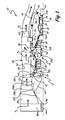
- FIG. 1 is a schematic cross-sectional view of a two-and-a-half spool turbofan engine having a reversed flow axial core.
- FIG. 2 is a schematic cross-sectional view of a three spool turbofan engine having a reversed flow axial core.
- FIG. 1 is a schematic cross-sectional view of two-and-a-half spool turbofan engine 10 having fan drive gear system 12, cross-flow low pressure spool 14, reversed-flow high pressure spool 16 and combustor section 18.
- Fan drive gear system 12 includes fan blades 20A and 20B, fan shaft 22, gearbox 24 and gear shaft 25.
- Cross-flow low pressure spool 14 includes low pressure compressor 26, low pressure shaft 28 and low pressure turbine 30.
- Reversed-flow high pressure spool 16 includes high pressure turbine 32, high pressure shaft 34 and high pressure compressor 36.
- turbofan engine 10 comprises a 2.5 spool engine: two spools represented by cross-flow low pressure spool 14 and reversed-flow high pressure spool 16, and a half-spool represented by fan drive gear system 12.
- turbofan engine 10 routes air and gas through fan drive gear system 12, low pressure spool 14 and high pressure spool 16 to efficiently produce thrust in an axially and radially compact engine architecture.
- Engine 10 also includes fan case 38, exhaust duct 40, flow splitter 42, compressor case 43, core engine case 44, reverse duct 46 and exhaust pipe 48 for directing flow of air through fan drive gear system 12, low pressure spool 14, high pressure spool 16 and combustor section 18.
- Fan case 38 surrounds fan blades 20A and 20B.
- Exhaust duct 40 which includes outer cowling 50 and inner cowling 52, extends from fan case 38 to the rear of engine 10.
- Flow splitter 42 is positioned at the upstream end of inner cowling 52.
- High pressure spool 16 is surrounded by engine case 44.
- Reverse duct 46 which is disposed between inner cowling 52 and engine case 44, comprises inner cowling 54 and outer cowling 56.
- Engine 10 also includes guide vanes 58A - 58C, high spool accessory gearbox system 62, low spool accessory gearbox system 64, heat exchanger 66, augmenter 68, low spool bearings 70A, 70B and 70C, high spool bearings 72A and 72B, fan bearings 74A and 74B, tower shaft 76, gearbox 78 and balance piston 80.
- Inlet air A I enters engine 10 through inlet guide vane 58A, passes through fan blade 20A, guide vane 58B and fan blade 20B, where flow splitter 42 divides inlet air A I into fan air A F and core air A C .
- Fan blades 20A and 20B accelerate inlet air A I to produce fan air A F , which produces a majority of the thrust generated by engine 10.
- Fan air A F continues past guide vane 58C and into exhaust duct 40 between outer cowling 50 and inner cowling 52.
- a portion of inlet air A I , core air A C is diverted from fan air A F to provide air for operating low pressure spool 14 and high pressure spool 16.
- core air A C flows into low pressure compressor 26.
- Compressor case 43 extends from flow splitter 42 to the inlet of compressor 26, and continues to the outlet of compressor 26.
- Reverse duct 46 extends radially outward from the outlet of compressor 26 and extends axially past low pressure turbine 30 and high pressure spool 16, where duct 46 turns radially inward toward high pressure spool 16.
- Reverse duct 46 includes an elbow or bend that turns reverse duct one-hundred-eighty degrees.
- High pressure spool 16 and low pressure turbine 30 are bounded by core engine case 44.
- the outlet of reverse duct 46 connects to the inlet of core engine case 44 to direct core air A C from low pressure compressor 26 into high pressure compressor 36.
- High pressure compressor 36 compresses core air A C in the axially upstream direction before being passed into combustor section 18 while still flowing in the upstream direction.
- core air A C is mixed with a fuel from a fuel system (not shown) and ignited to produce high energy gases for turning turbines 32 and 30. From combustor section 18, core air A C travels into high pressure turbine 32 and into low pressure turbine 30. As such, core air A C flows in an axially upstream direction from high pressure compressor 36 to low pressure turbine 30.
- Gearbox 24 comprises a gear system that steps down the rotational output of compressor 26 such that fan shaft 22 rotates at a lower speed than low pressure shaft 28.
- gearbox 24 comprises an epicyclic gear system.
- gear shaft 25 is connected to a sun gear and fan shaft 22 is connected to a ring gear, with a plurality of star gears being disposed between the sun gear and the ring gear.
- the star gears are mounted on bearing pins that are connected to a gear carrier that is stationarily affixed to engine 10.
- fan shaft 22 rotates slower than gear shaft 25 as the star gears rotate between the sun gear and ring gear.
- Such epicyclic gear systems are described in U.S. Pat. No. 6,223,616 to Sheridan , U.S. Pat. App. No. 2009/0056306 to Suciu et al. , and U.S. Pat. App. No.
- engine 10 comprises a three spool system in which low pressure turbine 30 is split into two turbines, one for directly powering low pressure compressor 26, and one for directly powering gearbox 24.
- Exhaust pipe 48 From low pressure turbine 30, core air A C is directed radially outward by exhaust pipe 48.
- the inlet of exhaust pipe 48 connects to engine case 44 and the outlet is disposed within exhaust duct 40.
- Exhaust pipe 48 comprises one of a plurality of ducts or vents having generally rectangular cross-sections that extend through inner cowling 52.
- Exhaust pipe 48 extends radially through inner and outer cowlings 54 and 56 of reverse duct 46.
- the outlet of exhaust pipe 48 is angled such that core air A C is able to leave exhaust pipe 48 in an axially downstream direction. In one embodiment, the outlet of exhaust pipe 48 is angled at forty-five degrees with respect to the axial direction.
- Core air A C leaves exhaust pipe 48 and enters exhaust duct 40 where core air A C becomes entrained and mixed with fan air A F .
- Exhaust air A E is discharged out of the outlet end of exhaust duct 40 to exit engine 10.
- Engine 10 comprises a fan drive gear system in conjunction with a reversed-flow high pressure spool and a cross-flow low pressure spool.
- Low pressure spool 14 comprises rearward-flow compressor 26 and forward-flow turbine 30, both of which are disposed axially forward of combustor section 18.
- High pressure spool 16 comprises forward-flow high pressure turbine 32 and forward-flow high pressure compressor 36, which are disposed axially forward and aft of combustor section 18, respectively. Configured as such, engine 10 achieves size, space and performance improvements as compared to conventional two spool turbofan engines without reversed-flow spool 16 and fan drive gear system 12.
- high pressure spool 16 comprises a center-tie core, as is described in U.S. Patent No. 7,309,210 by Suciu and Norris, which is assigned to United Technologies Corporation.
- high pressure turbine 32 and high pressure compressor 36 can be individually configured as center-tie rotors.
- High pressure spool 16 can also be configured using other, conventional rotor assemblies.
- high pressure compressor 36 comprises an axial flow compressor, in which a series of rotating blades force air or gas through a series of stationary vanes in an axial direction.
- compressor 36 comprises a series of disks, center-tied or otherwise, positioned between a pair of rotors connected to shaft 34.
- a plurality of blades extend from the disks and a plurality of vanes extend from engine duct 44 to form a flow path having a decreasing cross-sectional area in the direction of flow.
- Axial flow compressors are capable of efficiently producing large pressure ratios in radially compact designs, particularly as compared to radial or centrifugal compressors.
- the length of low pressure shaft 28 is significantly reduced as the need to pass through high pressure spool 16 is eliminated.
- the reduced length of shaft 28 further permits the diameter of shaft 28 to be reduced without sacrificing critical speed margin.
- the diameter of high pressure spool 16 can also be reduced.
- the size and weight of rotors and disks comprising high pressure turbine 32 and high pressure compressor 36 can be reduced. Reducing the size of components within engine 10 correspondingly reduces costs associated with manufacturing parts from high strength engine alloys.
- High pressure spool 16 is supported at various positions along high pressure shaft 34 by bearings 72A and 72B. In conventional flow gas turbine engines, the bearings are typically custom made. Reducing the size of high pressure spool 16 allows for reductions in the size of high pressure shaft 34, which enables the size of the bearings needed to support shaft 34 to also be reduced.
- Bearings are rated to a DN number, the diameter of the bearing multiplied by the speed at which the bearing will rotate in use. Lower rated bearings can be used if the critical speed of high pressure shaft 34 is maintained constant while the diameter of the bearing is reduced as the diameter of shaft 34 is reduced. Thus, smaller, lighter and less technically advanced bearings may be used to support shaft 34, which are typically less expensive than larger and heavier custom bearings.
- the reduced size of high pressure spool 16 allows for the rotational speed of high pressure shaft 34 to be increased without increasing high compressor blade tip speeds to unacceptable levels. As such, a high overall pressure ratio within engine 10 can be maintained.
- engine 10 when combined with fan drive gear system 12, engine 10 is able to efficiently generate a large proportion of overall thrust from fan blades 20A and 20B, which improves fuel efficiency and reduces engine noise.
- the reduced size of engine 10 also provides other structural benefits. For example, a reduction in the length of low pressure shaft 28 reduces the likelihood of undesirable flexing of shaft 28. This is particularly advantageous when engine 10 is used in aircraft involved in aircraft carrier operations where touchdown events give rise to shaft flexures.
- Exhaust air A E comprises a mixture of fan air A F and hotter core air A C .
- the mixed air reduces the overall temperature signature of exhausted gases, which reduces the infrared (IR) signature of engine 10.
- reverse duct 46 encapsulates combustor section 18 within engine 10 such that the line-of-sight of low pressure spool 14 and high pressure spool 16 is obstructed, further reducing the IR signature.
- the encapsulation of high pressure spool 16 and low pressure spool 14 also reduces the radar signature of engine 10 as the blades of the turbines are shielded from the line-of-sight of radar signals.
- exhaust from engine 10 is improved by mixing of core air A C from exhaust pipe 48 and fan air A F within exhaust duct 40, which reduces exhaust gas noise as the two gas streams are mixed within the engine before exiting. Additionally, core air A C directly leaving combustor 18 is facing axially upstream into engine 10 rather than being directly exhausted from the engine. All of these benefits reduce the need for providing engine 10 with specialized exhaust nozzles and cowling for reducing noise, heat and IR signatures.
- the ductwork surrounding engine 10 also provides other structural benefits. For example, exhaust duct 40 and reverse duct 46 provide an exoskeleton to engine 10 that reduces shaft bending within engine 10, and can be used to provide support for accessories mounted to engine 10.
- FIG. 1 shows schematically the positions of various subsystems used within engine 10.
- Engine 10 includes high spool accessory gearbox system 62, low spool accessory gearbox system 64, heat exchanger 66, augmenter 68, low spool bearings 70A, 70B and 70C, high spool bearings 72A and 72B, fan spool bearings 74A and 74B, tower shaft 76, gearbox 78 and balance piston 80.
- the architecture of low pressure shaft 28 and high pressure shaft 34, as well as exhaust duct 40 and reverse duct 46 allow such subsystems, such as heat exchanger 66, augmenter 68 and gearbox system 62, to be advantageously mounted within engine 10.
- Engine 10 includes accessory gearbox systems 62 and 64 for providing power to various sub-systems within engine 10.
- gearbox systems 62 and 64 can be used to drive generators for providing electrical power to engine 10 or the aircraft in which the engine is used.
- high pressure spool 16 is configured as a reversed-flow spool and low pressure spool 14 as a cross-flow spool, both high pressure shaft 34 and low pressure shaft 28 are easily accessible within engine 10. Because shaft 34 is not concentrically enshrouded within a low pressure spool shaft, power can be taken directly from high pressure spool 16. Furthermore, high pressure shaft 34 is positioned at the rear of engine 10 away from the flow of hot gases exiting combustor section 18 and turbines 30 and 32.
- shaft 34 can be directly accessed from the rear of engine 10 without disassembly. Also, the rearward end of shaft 34 is accessible such that power can be taken axially from shaft 34 without use of gear trains and shafts for changing the rotational orientation of shaft 34. For example, use of bevel gears or tower shafts is eliminated. However, conventional accessory gear trains can still be used to obtain power from low pressure shaft 28 or high pressure shaft 34. For example, an accessory gearbox can be conventionally connected to shaft 28 using tower shaft 76 and angle gearbox 78. Other suitable accessory gearbox assemblies for use with generators in the engine of present invention are described in U.S. Pat. App. No. 2009/0007569 to Lemmers, Jr. et al. , and U.S. Pat. App. No. 2008/0200299 to Russ , both of which are assigned to United Technologies Corporation.
- Engine 10 also facilitates easy use of inter-cooling and recuperating.
- Inter-cooling involves lowering the temperature of core air A C between low pressure compressor 26 and high pressure compressor 36 such that the amount of work required to compress the air is reduced.
- Inter-cooling is typically performed during take-off or other high heat operations to cool compressor air.
- inter-cooling is obtained within gas turbine engines by the use of heat exchangers that are positioned to receive airflow between the low pressure compressor and the high pressure compressor. Such systems require the use of additional ductwork and a heat exchanger, which add weight and expense to the engine system.
- the configuration of reverse duct 46 between low pressure compressor 26 and high pressure compressor 36 provides an integrated inter-cooling duct.
- the time it takes core air A C to travel through duct 46 provides an opportunity for core air A C to cool on its own accord.
- the proximity of reverse duct 46 and exhaust duct 40 allows inter-cooling heat exchanger 66 to be easily integrated into engine 10. The need for heavy and complex ducting and heat exchangers is eliminated.
- Reverse duct 46 and exhaust duct 40 provide easily accessible platforms on which to mount heat exchanger 66 without the need for additional ductwork.
- Heat exchanger 66 comprises valves and other plumbing components to selectively route portions of exhaust air A E within exhaust duct 40 past portions of core air A C within reverse duct 46 to perform inter-cooling.
- heat exchanger 66 can be operated in a reverse mode to perform recuperation. Recuperation involves heating compressed air within engine 10 before combustion. More specifically, one method of recuperation involves heating compressed air from high pressure compressor 36 with exhaust air A E . In the embodiment shown, heat exchanger 66 is positioned aft of exhaust pipe 48 and augmenter 68 to be able to recuperate heat generated in combustor section 18 and augmenter 68. Recuperation increases fuel efficiency by reducing the amount of heat that combustor section 18 must provide. Furthermore, recuperation reduces the demands on compressors 26 and 36 as potential energy is added to the compressed air by the heat. Recuperation is particularly useful at cruising speeds where components of engine 10 are not challenged by temperature limitations.
- recuperation systems require additional ductwork and heat exchangers.
- the proximity of reverse duct 46 and exhaust duct 40 in the present invention provides a platform upon which heat exchanger 66 is easily integrated to perform both inter-cooling and recuperation.
- heat exchanger 66 operates to direct portions of exhaust air A E within exhaust duct 40 past portions of core air A C within reverse duct 46 in a reverse manner as compared to inter-cooling operations.
- Exhaust duct 40 of engine 10 also provides advantages in the engine architecture of the present invention.
- Exhaust duct 40 provides a platform upon which an augmentation system can be mounted.
- Augmenter 68 is mounted on exhaust duct 40 between inner cowling 50 and outer cowling 52.
- Augmenter 68 carries out a secondary combustion process in exhaust air A E to further increase the velocity and mass of exhaust air A E , as is known in the art.
- augmenter 68 includes fuel spray bars or spray rings, flame holders, igniters, augmentation liners, valves and other plumbing for operating augmented combustion. Fuel spray bars or rings inject fuel into exhaust air A E , which is ignited with an igniter after mixing with oxygen present in exhaust air A E , thereby further increasing its velocity and mass.
- Augmenter 68 may also include augmentation liners and other protective shielding that prevents heat damage to exhaust duct 40.
- Augmenter 68 can be positioned anywhere within exhaust duct 40 between exhaust pipe 48 and the outlet of duct 40. In other embodiments augmenter 68 can be positioned aft of exhaust duct 40.
- positioning augmenter 68 within exhaust duct 40 near exhaust pipe 48 has several advantages. First, the size of engine 10 need not be increased with augmenter 68 within exhaust duct 40. Neither the radial nor axial dimensions of engine 10 need to increase to accommodate an augmentation system. This is particularly advantageous for military engines where aircraft size and length is of concern. Furthermore, with augmenter 68 within duct 40, the line-of-sight of augmented combustion is concealed within engine 10 to reduce the noise, IR and radar signatures of engine 10.
- low pressure turbine 30 and low pressure compressor 26 both produce axial forces that push low pressure spool 14 in the axially forward direction.
- Engine 10 is provided with a thrust reactor system to counteract these axially forward forces.
- bearings are positioned at various places along fan shaft 22, low pressure shaft 28, gear shaft 25, high pressure shaft 34 and other places to support low pressure spool 14.
- low pressure shaft 28 is provided with bearings 70A, 70B and 70C to counteract forces generated by low pressure spool 14.
- High pressure shaft 34 is supported by bearings 72A and 72B to counteract forces generated by high pressure turbine 32 and compressor 36.
- fan shaft 22 is provided with bearings 74A and 74B to counteract forces generated by fan drive gear system 12.
- Bearings 70A - 70C, 72A and 72B, and 74A and 74B are supported within engine 12 by various support struts connected to stationary components within engine 10, such as compressor case 43 or engine case 44.
- bearings 74A and 74B are supported by inlet guide vane 58A.
- Bearings 70A - 70C, and 74A and 74B are configured to absorb forward oriented thrust.
- bearings 70A, 70B and 70C, and 74A and 74B comprise large-capacity tapered roller bearings.
- shaft 28 can be provided with balance piston 80 to apply additional counter force to low pressure spool 14 in addition to what is provided by bearings 70A - 70C.
- Balance piston 80 can be anchored to a stationary component within engine 10, such as support struts for bearings 70A and 70B, and oriented to apply rearward axial force to shaft 28.
- the architecture of engine 10 provides advantages in structure and performance over other engine architectures. Reductions in the weight of low pressure shaft 28, and high pressure spool 16 offset weight increases from exhaust duct 40 and reverse duct 46. Additionally, the performance benefits of having larger fan blades and a smaller high pressure spool with efficient pressure ratios outweigh the performance concerns relating to duct losses, compressor stability issues, and shaft loading. Furthermore, structural stability on engine 10 resulting from exhaust duct 40 and reverse duct 46 and shortening of shafts within engine 10 provide further benefits, including the ability to easily mount subsystems within engine 10. As such, the fan drive gear system and reversed-flow core architecture of the present invention achieve advancements and improvements in the efficiency and structure of turbofan engines.
- FIG. 2 is a schematic cross-sectional view of three spool turbofan engine 10 having fan drive gear system 12, cross-flow low pressure spool 14, reversed-flow high pressure spool 16 and combustor section 18.
- Fan drive gear system 12 includes fan blades 20A and 20B, fan shaft 22, gearbox 24 and gear shaft 82, which are driven by intermediate pressure turbine 84.
- Cross-flow low pressure spool 14 includes low pressure compressor 26 and low pressure shaft 28, which are driven by low pressure turbine 30.
- Reversed-flow high pressure spool 16 includes high pressure shaft 34 and high pressure compressor 36, which are driven by high pressure turbine 32.
- turbofan engine 10 comprises a 3.0 spool engine: two spools represented by cross-flow low pressure spool 14 and reversed-flow high pressure spool 16, and a full spool represented by fan drive gear system 12.
- turbofan engine 10 routes air and gas through fan drive gear system 12, low pressure spool 14 and high pressure spool 16 to efficiently produce thrust in a radially and axially compact engine architecture, similar to that of FIG. 1 .
- the 3.0 spool configuration of FIG. 2 enables even greater flexibility in designing and operating engine 10.
- gear shaft 25 of FIG. 1 which connects gearbox 24 to low pressure compressor 26, is replaced with gear shaft 82.
- Gear shaft 82 connects gearbox 24 directly to turbine 84.
- Turbine 84 comprises a third turbine within engine 10 disposed between high pressure turbine 32 and low pressure turbine 30. In the embodiment shown, turbine 30 is shortened to accommodate turbine 84, as low pressure spool 14 need not power gearbox 24.
- the number of turbines used in engine 10 and the specific length, or number of stages, in each turbine can be selected based on desired performance parameters of engine 10. For example, a 3.0 spool system reduces the mass of each spool as compared to a 2.5 spool system. Reduced mass enables better acceleration of each spool as well as reducing the need for variable geometry vanes and blades. Thus, the output of turbines 30, 32 and 84 can more easily and more rapidly matched to the needs of compressor 26, compressor 36 and fan 38, respectively.
Landscapes
- Engineering & Computer Science (AREA)
- Chemical & Material Sciences (AREA)
- Combustion & Propulsion (AREA)
- Mechanical Engineering (AREA)
- General Engineering & Computer Science (AREA)
- Retarders (AREA)
- Structures Of Non-Positive Displacement Pumps (AREA)
- Control Of Turbines (AREA)
Abstract
Description
- The present invention is directed to multi-spool gas turbine engines and, in particular, to gas turbine engines having a reverse flow spool. Typical multi-spool turbofan gas turbine engines include a nested core, in which a high pressure, or core, spool is nested inside a low pressure spool. Such a nested core engine includes, in axial sequence, a low pressure compressor, a high pressure compressor, a combustor section, a high pressure turbine, and a low pressure turbine. The high pressure compressor is connected to the high pressure turbine with a high pressure shaft that extends through the combustor section. The low pressure compressor is connected to the low pressure turbine with a low pressure shaft that extends through the high pressure shaft. Increases in efficiency of the turbofan allow for the core to be reduced in size, such as by having a smaller diameter. The low pressure shaft, however, cannot be reduced in diameter because the rotational speeds of the low pressure spool are limited by critical speed. The shaft critical speed is proportional to the shaft diameter and inversely proportional to the shaft length. Thus, decreasing the shaft diameter with reduced core sizes is not possible without reducing the shaft length if the same critical speed is desired. Thus, reductions in the core size yield compromises in the high pressure spool to accommodate low pressure spool shaft diameters. For example, the size and weight of high pressure spool rotor disk need to be increased to accommodate openings for larger low pressure shaft sizes. As such, there is a need for improving engine architectures to allow for, among other things, decreased core sizes resulting from more efficient turbofan engines.
- The present invention is directed to a gas turbine engine comprising a fan drive gear system, a low spool connected to the fan drive gear system, and a high spool disposed aft of the low spool. The low spool comprises a rearward-flow low pressure compressor disposed aft of the fan drive gear system, and a forward-flow low pressure turbine disposed aft of the low pressure compressor. The high spool comprises a forward-flow high pressure turbine disposed aft of the low pressure turbine, a combustor disposed aft of the high pressure turbine, and a forward-flow high pressure compressor disposed aft of the combustor.
-
FIG. 1 is a schematic cross-sectional view of a two-and-a-half spool turbofan engine having a reversed flow axial core. -
FIG. 2 is a schematic cross-sectional view of a three spool turbofan engine having a reversed flow axial core. -
FIG. 1 is a schematic cross-sectional view of two-and-a-halfspool turbofan engine 10 having fandrive gear system 12, cross-flowlow pressure spool 14, reversed-flowhigh pressure spool 16 andcombustor section 18. Fandrive gear system 12 includesfan blades fan shaft 22,gearbox 24 andgear shaft 25. Cross-flowlow pressure spool 14 includeslow pressure compressor 26,low pressure shaft 28 andlow pressure turbine 30. Reversed-flowhigh pressure spool 16 includeshigh pressure turbine 32,high pressure shaft 34 andhigh pressure compressor 36. As such,turbofan engine 10 comprises a 2.5 spool engine: two spools represented by cross-flowlow pressure spool 14 and reversed-flowhigh pressure spool 16, and a half-spool represented by fandrive gear system 12. Using various ductwork,turbofan engine 10 routes air and gas through fandrive gear system 12,low pressure spool 14 andhigh pressure spool 16 to efficiently produce thrust in an axially and radially compact engine architecture. -
Engine 10 also includesfan case 38,exhaust duct 40,flow splitter 42,compressor case 43,core engine case 44,reverse duct 46 andexhaust pipe 48 for directing flow of air through fandrive gear system 12,low pressure spool 14,high pressure spool 16 andcombustor section 18.Fan case 38 surroundsfan blades Exhaust duct 40, which includesouter cowling 50 andinner cowling 52, extends fromfan case 38 to the rear ofengine 10.Flow splitter 42 is positioned at the upstream end ofinner cowling 52.High pressure spool 16 is surrounded byengine case 44.Reverse duct 46, which is disposed betweeninner cowling 52 andengine case 44, comprisesinner cowling 54 andouter cowling 56.Engine 10 also includesguide vanes 58A - 58C, high spoolaccessory gearbox system 62, low spoolaccessory gearbox system 64,heat exchanger 66, augmenter 68,low spool bearings high spool bearings fan bearings tower shaft 76,gearbox 78 andbalance piston 80. - Inlet air AI enters
engine 10 through inlet guide vane 58A, passes throughfan blade 20A,guide vane 58B andfan blade 20B, whereflow splitter 42 divides inlet air AI into fan air AF and core air AC. Fan blades 20A and 20B accelerate inlet air AI to produce fan air AF, which produces a majority of the thrust generated byengine 10. Fan air AF continuespast guide vane 58C and intoexhaust duct 40 between outer cowling 50 andinner cowling 52. A portion of inlet air AI, core air AC, is diverted from fan air AF to provide air for operatinglow pressure spool 14 andhigh pressure spool 16. Usingcompressor case 43, core air AC flows intolow pressure compressor 26.Compressor case 43 extends fromflow splitter 42 to the inlet ofcompressor 26, and continues to the outlet ofcompressor 26.Low pressure compressor 26, which is driven throughlow pressure shaft 28 bylow pressure turbine 30, compresses core air AC in the axially downstream direction. Compressed core air AC fromcompressor 26 is routed intoreverse duct 46 fromcompressor case 43. -
Reverse duct 46 extends radially outward from the outlet ofcompressor 26 and extends axially pastlow pressure turbine 30 andhigh pressure spool 16, whereduct 46 turns radially inward towardhigh pressure spool 16.Reverse duct 46 includes an elbow or bend that turns reverse duct one-hundred-eighty degrees.High pressure spool 16 andlow pressure turbine 30 are bounded bycore engine case 44. The outlet ofreverse duct 46 connects to the inlet ofcore engine case 44 to direct core air AC fromlow pressure compressor 26 intohigh pressure compressor 36.High pressure compressor 36 compresses core air AC in the axially upstream direction before being passed intocombustor section 18 while still flowing in the upstream direction. Withincombustor section 18, core air AC is mixed with a fuel from a fuel system (not shown) and ignited to produce high energy gases for turningturbines combustor section 18, core air AC travels intohigh pressure turbine 32 and intolow pressure turbine 30. As such, core air AC flows in an axially upstream direction fromhigh pressure compressor 36 tolow pressure turbine 30. - Flow of core air AC through
turbines compressor 36 andcompressor 26, respectively, to provide the compressed air necessary for producing and sustaining combustion withincombustor section 18.Low pressure compressor 26 is driven bylow pressure turbine 30 throughlow pressure shaft 28.High pressure compressor 36 is driven byhigh pressure turbine 32 throughhigh pressure shaft 34, which extends throughcombustor section 18. Furthermore, rotation oflow pressure compressor 26 produces rotation offan blades gearbox 24,fan shaft 22 andgear shaft 25. Gearbox 24 comprises a gear system that steps down the rotational output ofcompressor 26 such thatfan shaft 22 rotates at a lower speed thanlow pressure shaft 28. In one embodiment,gearbox 24 comprises an epicyclic gear system. In one such embodiment,gear shaft 25 is connected to a sun gear andfan shaft 22 is connected to a ring gear, with a plurality of star gears being disposed between the sun gear and the ring gear. The star gears are mounted on bearing pins that are connected to a gear carrier that is stationarily affixed toengine 10. As such,fan shaft 22 rotates slower thangear shaft 25 as the star gears rotate between the sun gear and ring gear. Such epicyclic gear systems are described inU.S. Pat. No. 6,223,616 to Sheridan ,U.S. Pat. App. No. 2009/0056306 toSuciu et al. U.S. Pat. App. No. 2009/0090096 to Sheridan, each of which is assigned to United Technologies Corporation, Hartford, Connecticut. In another embodiment of the invention discussed with reference toFIG. 2 ,engine 10 comprises a three spool system in whichlow pressure turbine 30 is split into two turbines, one for directly poweringlow pressure compressor 26, and one for directly poweringgearbox 24. - From
low pressure turbine 30, core air AC is directed radially outward byexhaust pipe 48. The inlet ofexhaust pipe 48 connects toengine case 44 and the outlet is disposed withinexhaust duct 40.Exhaust pipe 48 comprises one of a plurality of ducts or vents having generally rectangular cross-sections that extend throughinner cowling 52.Exhaust pipe 48 extends radially through inner andouter cowlings reverse duct 46. The outlet ofexhaust pipe 48 is angled such that core air AC is able to leaveexhaust pipe 48 in an axially downstream direction. In one embodiment, the outlet ofexhaust pipe 48 is angled at forty-five degrees with respect to the axial direction. Core air AC leavesexhaust pipe 48 and entersexhaust duct 40 where core air AC becomes entrained and mixed with fan air AF. Exhaust air AE is discharged out of the outlet end ofexhaust duct 40 to exitengine 10. -
Engine 10 comprises a fan drive gear system in conjunction with a reversed-flow high pressure spool and a cross-flow low pressure spool.Low pressure spool 14 comprises rearward-flow compressor 26 and forward-flow turbine 30, both of which are disposed axially forward ofcombustor section 18.High pressure spool 16 comprises forward-flowhigh pressure turbine 32 and forward-flowhigh pressure compressor 36, which are disposed axially forward and aft ofcombustor section 18, respectively. Configured as such,engine 10 achieves size, space and performance improvements as compared to conventional two spool turbofan engines without reversed-flow spool 16 and fandrive gear system 12. - In one embodiment,
high pressure spool 16 comprises a center-tie core, as is described inU.S. Patent No. 7,309,210 by Suciu and Norris, which is assigned to United Technologies Corporation. However,high pressure turbine 32 andhigh pressure compressor 36 can be individually configured as center-tie rotors.High pressure spool 16 can also be configured using other, conventional rotor assemblies. In the embodiment of the invention shown,high pressure compressor 36 comprises an axial flow compressor, in which a series of rotating blades force air or gas through a series of stationary vanes in an axial direction. For example,compressor 36 comprises a series of disks, center-tied or otherwise, positioned between a pair of rotors connected toshaft 34. A plurality of blades extend from the disks and a plurality of vanes extend fromengine duct 44 to form a flow path having a decreasing cross-sectional area in the direction of flow. Axial flow compressors are capable of efficiently producing large pressure ratios in radially compact designs, particularly as compared to radial or centrifugal compressors. - The length of
low pressure shaft 28 is significantly reduced as the need to pass throughhigh pressure spool 16 is eliminated. The reduced length ofshaft 28 further permits the diameter ofshaft 28 to be reduced without sacrificing critical speed margin. Without the need to accommodateshaft 28, the diameter ofhigh pressure spool 16 can also be reduced. Thus, the size and weight of rotors and disks comprisinghigh pressure turbine 32 andhigh pressure compressor 36 can be reduced. Reducing the size of components withinengine 10 correspondingly reduces costs associated with manufacturing parts from high strength engine alloys. -
Engine 10 also allows for weight and cost reductions by eliminating the need for large, expensive bearings.High pressure spool 16 is supported at various positions alonghigh pressure shaft 34 bybearings high pressure spool 16 allows for reductions in the size ofhigh pressure shaft 34, which enables the size of the bearings needed to supportshaft 34 to also be reduced. Bearings are rated to a DN number, the diameter of the bearing multiplied by the speed at which the bearing will rotate in use. Lower rated bearings can be used if the critical speed ofhigh pressure shaft 34 is maintained constant while the diameter of the bearing is reduced as the diameter ofshaft 34 is reduced. Thus, smaller, lighter and less technically advanced bearings may be used to supportshaft 34, which are typically less expensive than larger and heavier custom bearings. - The reduced size of
high pressure spool 16 allows for the rotational speed ofhigh pressure shaft 34 to be increased without increasing high compressor blade tip speeds to unacceptable levels. As such, a high overall pressure ratio withinengine 10 can be maintained. Thus, when combined with fandrive gear system 12,engine 10 is able to efficiently generate a large proportion of overall thrust fromfan blades engine 10 also provides other structural benefits. For example, a reduction in the length oflow pressure shaft 28 reduces the likelihood of undesirable flexing ofshaft 28. This is particularly advantageous whenengine 10 is used in aircraft involved in aircraft carrier operations where touchdown events give rise to shaft flexures. - The ductwork that encapsulates
low pressure spool 14 andhigh pressure spool 16 also provides benefits and advantages toengine 10. Exhaust air AE comprises a mixture of fan air AF and hotter core air AC. The mixed air reduces the overall temperature signature of exhausted gases, which reduces the infrared (IR) signature ofengine 10. Furthermore, reverseduct 46 encapsulatescombustor section 18 withinengine 10 such that the line-of-sight oflow pressure spool 14 andhigh pressure spool 16 is obstructed, further reducing the IR signature. The encapsulation ofhigh pressure spool 16 andlow pressure spool 14 also reduces the radar signature ofengine 10 as the blades of the turbines are shielded from the line-of-sight of radar signals. Release of exhaust fromengine 10 is improved by mixing of core air AC fromexhaust pipe 48 and fan air AF withinexhaust duct 40, which reduces exhaust gas noise as the two gas streams are mixed within the engine before exiting. Additionally, core air AC directly leavingcombustor 18 is facing axially upstream intoengine 10 rather than being directly exhausted from the engine. All of these benefits reduce the need for providingengine 10 with specialized exhaust nozzles and cowling for reducing noise, heat and IR signatures. Theductwork surrounding engine 10 also provides other structural benefits. For example,exhaust duct 40 and reverseduct 46 provide an exoskeleton toengine 10 that reduces shaft bending withinengine 10, and can be used to provide support for accessories mounted toengine 10. -
FIG. 1 shows schematically the positions of various subsystems used withinengine 10.Engine 10 includes high spoolaccessory gearbox system 62, low spoolaccessory gearbox system 64,heat exchanger 66,augmenter 68,low spool bearings high spool bearings fan spool bearings tower shaft 76,gearbox 78 andbalance piston 80. The architecture oflow pressure shaft 28 andhigh pressure shaft 34, as well asexhaust duct 40 and reverseduct 46 allow such subsystems, such asheat exchanger 66,augmenter 68 andgearbox system 62, to be advantageously mounted withinengine 10. -
Engine 10 includesaccessory gearbox systems engine 10. Forexample gearbox systems engine 10 or the aircraft in which the engine is used. By configuringhigh pressure spool 16 as a reversed-flow spool andlow pressure spool 14 as a cross-flow spool, bothhigh pressure shaft 34 andlow pressure shaft 28 are easily accessible withinengine 10. Becauseshaft 34 is not concentrically enshrouded within a low pressure spool shaft, power can be taken directly fromhigh pressure spool 16. Furthermore,high pressure shaft 34 is positioned at the rear ofengine 10 away from the flow of hot gases exitingcombustor section 18 andturbines shaft 34 can be directly accessed from the rear ofengine 10 without disassembly. Also, the rearward end ofshaft 34 is accessible such that power can be taken axially fromshaft 34 without use of gear trains and shafts for changing the rotational orientation ofshaft 34. For example, use of bevel gears or tower shafts is eliminated. However, conventional accessory gear trains can still be used to obtain power fromlow pressure shaft 28 orhigh pressure shaft 34. For example, an accessory gearbox can be conventionally connected toshaft 28 usingtower shaft 76 andangle gearbox 78. Other suitable accessory gearbox assemblies for use with generators in the engine of present invention are described inU.S. Pat. App. No. 2009/0007569 to Lemmers, Jr. et al. , andU.S. Pat. App. No. 2008/0200299 to Russ , both of which are assigned to United Technologies Corporation. -
Engine 10 also facilitates easy use of inter-cooling and recuperating. Inter-cooling involves lowering the temperature of core air AC betweenlow pressure compressor 26 andhigh pressure compressor 36 such that the amount of work required to compress the air is reduced. Inter-cooling is typically performed during take-off or other high heat operations to cool compressor air. Conventionally, inter-cooling is obtained within gas turbine engines by the use of heat exchangers that are positioned to receive airflow between the low pressure compressor and the high pressure compressor. Such systems require the use of additional ductwork and a heat exchanger, which add weight and expense to the engine system. In the present invention, the configuration ofreverse duct 46 betweenlow pressure compressor 26 andhigh pressure compressor 36 provides an integrated inter-cooling duct. Specifically, the time it takes core air AC to travel throughduct 46 provides an opportunity for core air AC to cool on its own accord. Furthermore, the proximity ofreverse duct 46 andexhaust duct 40 allowsinter-cooling heat exchanger 66 to be easily integrated intoengine 10. The need for heavy and complex ducting and heat exchangers is eliminated.Reverse duct 46 andexhaust duct 40 provide easily accessible platforms on which to mountheat exchanger 66 without the need for additional ductwork.Heat exchanger 66 comprises valves and other plumbing components to selectively route portions of exhaust air AE withinexhaust duct 40 past portions of core air AC withinreverse duct 46 to perform inter-cooling. - Similarly,
heat exchanger 66 can be operated in a reverse mode to perform recuperation. Recuperation involves heating compressed air withinengine 10 before combustion. More specifically, one method of recuperation involves heating compressed air fromhigh pressure compressor 36 with exhaust air AE. In the embodiment shown,heat exchanger 66 is positioned aft ofexhaust pipe 48 andaugmenter 68 to be able to recuperate heat generated incombustor section 18 andaugmenter 68. Recuperation increases fuel efficiency by reducing the amount of heat that combustorsection 18 must provide. Furthermore, recuperation reduces the demands oncompressors engine 10 are not challenged by temperature limitations. As with inter-cooling, conventional recuperation systems require additional ductwork and heat exchangers. The proximity ofreverse duct 46 andexhaust duct 40 in the present invention provides a platform upon whichheat exchanger 66 is easily integrated to perform both inter-cooling and recuperation. To perform recuperation,heat exchanger 66 operates to direct portions of exhaust air AE withinexhaust duct 40 past portions of core air AC withinreverse duct 46 in a reverse manner as compared to inter-cooling operations. -
Exhaust duct 40 ofengine 10 also provides advantages in the engine architecture of the present invention.Exhaust duct 40 provides a platform upon which an augmentation system can be mounted. For example,augmenter 68 is mounted onexhaust duct 40 betweeninner cowling 50 andouter cowling 52.Augmenter 68 carries out a secondary combustion process in exhaust air AE to further increase the velocity and mass of exhaust air AE, as is known in the art. In one embodiment of the invention,augmenter 68 includes fuel spray bars or spray rings, flame holders, igniters, augmentation liners, valves and other plumbing for operating augmented combustion. Fuel spray bars or rings inject fuel into exhaust air AE, which is ignited with an igniter after mixing with oxygen present in exhaust air AE, thereby further increasing its velocity and mass. Flame holders produce local turbulence downstream of fuel spray bars to maintain flame stability.Augmenter 68 may also include augmentation liners and other protective shielding that prevents heat damage toexhaust duct 40.Augmenter 68 can be positioned anywhere withinexhaust duct 40 betweenexhaust pipe 48 and the outlet ofduct 40. In other embodiments augmenter 68 can be positioned aft ofexhaust duct 40. However, positioningaugmenter 68 withinexhaust duct 40 nearexhaust pipe 48 has several advantages. First, the size ofengine 10 need not be increased withaugmenter 68 withinexhaust duct 40. Neither the radial nor axial dimensions ofengine 10 need to increase to accommodate an augmentation system. This is particularly advantageous for military engines where aircraft size and length is of concern. Furthermore, withaugmenter 68 withinduct 40, the line-of-sight of augmented combustion is concealed withinengine 10 to reduce the noise, IR and radar signatures ofengine 10. - In a conventional axial flow spool, the compressor and turbine produce axially opposing forces. Thus, the shaft connecting the compressor and turbine is put into tension, and the loading on the spool is borne by conventional bearings. However, in the counter flow spool design of
engine 10,low pressure turbine 30 andlow pressure compressor 26 both produce axial forces that pushlow pressure spool 14 in the axially forward direction.Engine 10 is provided with a thrust reactor system to counteract these axially forward forces. For example, bearings are positioned at various places alongfan shaft 22,low pressure shaft 28,gear shaft 25,high pressure shaft 34 and other places to supportlow pressure spool 14. Specifically,low pressure shaft 28 is provided withbearings low pressure spool 14.High pressure shaft 34 is supported bybearings high pressure turbine 32 andcompressor 36. Similarly,fan shaft 22 is provided withbearings drive gear system 12.Bearings 70A - 70C, 72A and 72B, and 74A and 74B are supported withinengine 12 by various support struts connected to stationary components withinengine 10, such ascompressor case 43 orengine case 44. For example,bearings inlet guide vane 58A.Bearings 70A - 70C, and 74A and 74B are configured to absorb forward oriented thrust. In one embodiment,bearings shaft 28 can be provided withbalance piston 80 to apply additional counter force tolow pressure spool 14 in addition to what is provided bybearings 70A - 70C.Balance piston 80 can be anchored to a stationary component withinengine 10, such as support struts forbearings shaft 28. - Thus, the architecture of
engine 10 provides advantages in structure and performance over other engine architectures. Reductions in the weight oflow pressure shaft 28, andhigh pressure spool 16 offset weight increases fromexhaust duct 40 and reverseduct 46. Additionally, the performance benefits of having larger fan blades and a smaller high pressure spool with efficient pressure ratios outweigh the performance concerns relating to duct losses, compressor stability issues, and shaft loading. Furthermore, structural stability onengine 10 resulting fromexhaust duct 40 and reverseduct 46 and shortening of shafts withinengine 10 provide further benefits, including the ability to easily mount subsystems withinengine 10. As such, the fan drive gear system and reversed-flow core architecture of the present invention achieve advancements and improvements in the efficiency and structure of turbofan engines. -
FIG. 2 is a schematic cross-sectional view of threespool turbofan engine 10 having fandrive gear system 12, cross-flowlow pressure spool 14, reversed-flowhigh pressure spool 16 andcombustor section 18. In the 3.0 spool configuration, each spool is directly driven by a turbine to form three full spools. Fandrive gear system 12 includesfan blades fan shaft 22,gearbox 24 andgear shaft 82, which are driven byintermediate pressure turbine 84. Cross-flowlow pressure spool 14 includeslow pressure compressor 26 andlow pressure shaft 28, which are driven bylow pressure turbine 30. Reversed-flowhigh pressure spool 16 includeshigh pressure shaft 34 andhigh pressure compressor 36, which are driven byhigh pressure turbine 32. As such,turbofan engine 10 comprises a 3.0 spool engine: two spools represented by cross-flowlow pressure spool 14 and reversed-flowhigh pressure spool 16, and a full spool represented by fandrive gear system 12. - Using various ductwork,
turbofan engine 10 routes air and gas through fandrive gear system 12,low pressure spool 14 andhigh pressure spool 16 to efficiently produce thrust in a radially and axially compact engine architecture, similar to that ofFIG. 1 . The 3.0 spool configuration ofFIG. 2 , however, enables even greater flexibility in designing andoperating engine 10. InFIG. 2 ,gear shaft 25 ofFIG. 1 , which connectsgearbox 24 tolow pressure compressor 26, is replaced withgear shaft 82.Gear shaft 82 connectsgearbox 24 directly toturbine 84.Turbine 84 comprises a third turbine withinengine 10 disposed betweenhigh pressure turbine 32 andlow pressure turbine 30. In the embodiment shown,turbine 30 is shortened to accommodateturbine 84, aslow pressure spool 14 need notpower gearbox 24. The number of turbines used inengine 10 and the specific length, or number of stages, in each turbine, however, can be selected based on desired performance parameters ofengine 10. For example, a 3.0 spool system reduces the mass of each spool as compared to a 2.5 spool system. Reduced mass enables better acceleration of each spool as well as reducing the need for variable geometry vanes and blades. Thus, the output ofturbines compressor 26,compressor 36 andfan 38, respectively. - While the invention has been described with reference to an exemplary embodiment(s), it will be understood by those skilled in the art that various changes may be made and equivalents may be substituted for elements thereof without departing from the scope of the invention. In addition, many modifications may be made to adapt a particular situation or material to the teachings of the invention without departing from the essential scope thereof. Therefore, it is intended that the invention not be limited to the particular embodiment(s) disclosed, but that the invention will include all embodiments falling within the scope of the appended claims.
Claims (15)
- A gas turbine engine comprising:a fan drive gear system;a low spool connected to the fan drive gear system, the low spool comprising:a rearward-flow low pressure compressor disposed aft of the fan drive gear system; anda forward-flow low pressure turbine disposed aft of the low pressure compressor; anda high spool disposed aft of the low spool, the high spool comprising:a forward-flow high pressure turbine disposed aft of the low pressure turbine;a combustor disposed aft of the high pressure turbine; anda forward-flow high pressure compressor disposed aft of the combustor.
- The gas turbine engine of claim 1 wherein flow through the engine extends sequentially through the low pressure compressor in a downstream direction, and through the high pressure compressor, the combustor, the high pressure turbine and the low pressure turbine in a forward direction.
- The gas turbine engine of claim 2 wherein the fan drive gear system comprises:a turbofan;a fan shaft connected to an inner diameter of the turbofan; andan epicyclic gear system connected to a downstream end of the fan shaft.
- The gas turbine engine of claim 3 and further comprising:a low pressure shaft comprising:a forward portion connected to the epicyclic gear system;a mid portion connected to the low pressure compressor; andan aft portion connected to the low pressure turbine; anda high pressure shaft disposed axially downstream of the low pressure shaft, the high pressure shaft comprising:a forward portion connected to the high pressure turbine;a mid portion extending concentrically through the combustor; andan aft portion connected to the high pressure compressor.
- The gas turbine engine of claim 3 and further comprising:an intermediate pressure turbine disposed between the low pressure turbine and the high pressure turbine;a gear shaft connecting the epicyclic gear system to the intermediate pressure turbine;a low pressure shaft comprising:a forward portion connected to the low pressure compressor; andan aft portion connected to the low pressure turbine; anda high pressure shaft disposed axially downstream of the low pressure shaft, the high pressure shaft comprising:a forward portion connected to the high pressure turbine;a mid portion extending concentrically through the combustor; andan aft portion connected to the high pressure compressor.
- The gas turbine engine of claim 4 or 5 and further comprising an accessory gearbox extending axially from a downstream end of the high pressure shaft; and/or further comprising an accessory gearbox extending radially from the low pressure shaft using a tower shaft; and/or further comprising a balance piston and a tapered roller bearing connected to the low pressure shaft to react axially forward directed thrust on the low pressure spool.
- The gas turbine engine of claim 3, 4, 5 or 6 and further comprising:reverse ducting disposed radially outward of the high spool for directing output of the low pressure compressor to the high pressure compressor such that the output reverses flow to pass through the high spool; andexhaust ducting disposed radially outward of the reverse ducting for receiving exhaust gas from the low pressure turbine and fan air from the turbofan.
- The turbine engine of claim 7 and further comprising an intercooling and recuperating heat exchanger mounted adjacent the reverse ducting between the low pressure compressor and the high pressure compressor; and/or further comprising an augmenter mounted within the exhaust ducting radially outward of the high pressure spool.
- The gas turbine engine of any of claims 3 to 8 and further comprising:an annular exhaust duct for guiding fan air from the turbofan;a flow splitter disposed within the exhaust duct to divert a portion of the fan air to the low pressure compressor to produce a downstream flow of low pressure air;a core engine case surrounding the high spool;a reverse flow duct disposed concentrically between the exhaust duct and the core engine case, the reverse flow duct comprising:an inlet end configured to receive downstream flow of the low pressure air from the low pressure compressor;an elbow connected to the inlet end and configured to redirect downstream flow of the low pressure air into upstream flow; andan outlet end connected to the elbow and configured to direct upstream flow of the low pressure air into the high pressure compressor; and an exhaust vent comprising:an inlet configured to receive gas from the core engine case; andan outlet configured to discharge gas into the annular exhaust duct.
- The gas turbine engine of any preceding claim wherein the high pressure compressor comprises an axial flow compressor.
- A turbofan engine comprising:a turbofan propulsor for producing downstream flowing bypass gas and core gas;a cross-flow low pressure spool comprising:a low pressure compressor for receiving downstream flowing core gas from the turbofan propulsor; anda low pressure turbine having upstream flow;a gear reduction system for coupling the turbofan propulsor to an input rotation;an air duct for turning downstream flowing core gas from the low pressure compressor radially inward for upstream flow;a reversed-flow core with upstream flow configured to receive upstream flowing core gas from the air duct and to deliver upstream flowing core gas to the low pressure turbine; andan exhaust pipe for turning upstream flow of core gas from the low pressure turbine radially outward for discharge into the downstream flow of bypass gas;preferably wherein the reversed-flow core includes an axial flow high pressure turbine and an axial flow high pressure compressor.
- The turbofan engine of claim 11 and further comprising:a fan shaft for connecting the turbofan propulsor to the gear reduction system;a low pressure shaft for connecting the low pressure compressor to the low pressure turbine; anda high pressure shaft for connecting the high pressure compressor to the high pressure turbine.
- The turbofan engine of claim 12 and further comprising a gear shaft for connecting the gear reduction system to the cross-flow low pressure spool, the gear shaft providing the input rotation; or further comprising:an intermediate pressure turbine disposed between the low pressure turbine and the high pressure turbine; anda gear shaft for connecting the gear reduction system to the intermediate pressure turbine, the gear shaft providing the input rotation.
- A method for operating a turbofan engine, the method comprising:generating an axially downstream flow of fan air with a fan drive gear system;splitting the fan air into a first portion directed downstream into an exhaust duct, and a second portion directed downstream into a low pressure compressor;redirecting compressed air from the low pressure compressor to a reverse flow duct to produce an axially upstream flow of compressed air;directing the upstream flow of compressed air sequentially through a high pressure compressor, a combustor, a high pressure turbine and a low pressure turbine to produce exhaust gas; andventing the exhaust gas into the exhaust duct to join the first portion of the fan air.
- The method of claim 14 wherein the reverse flow duct is radially inward of and concentric with the exhaust duct; and the high pressure compressor, the combustor, the high pressure turbine and the low pressure turbine are radially inward of and concentric with the reverse flow duct such that the exhaust gas is vented radially outward to the exhaust duct through the reverse flow duct.
Applications Claiming Priority (1)
| Application Number | Priority Date | Filing Date | Title |
|---|---|---|---|
| US12/556,359 US8176725B2 (en) | 2009-09-09 | 2009-09-09 | Reversed-flow core for a turbofan with a fan drive gear system |
Publications (3)
| Publication Number | Publication Date |
|---|---|
| EP2295763A2 true EP2295763A2 (en) | 2011-03-16 |
| EP2295763A3 EP2295763A3 (en) | 2013-03-13 |
| EP2295763B1 EP2295763B1 (en) | 2018-04-18 |
Family
ID=43014493
Family Applications (1)
| Application Number | Title | Priority Date | Filing Date |
|---|---|---|---|
| EP10251567.3A Active EP2295763B1 (en) | 2009-09-09 | 2010-09-09 | Reversed-flow core for a turbofan with a fan drive gear system |
Country Status (2)
| Country | Link |
|---|---|
| US (1) | US8176725B2 (en) |
| EP (1) | EP2295763B1 (en) |
Cited By (20)
| Publication number | Priority date | Publication date | Assignee | Title |
|---|---|---|---|---|
| EP2615289A1 (en) * | 2011-11-02 | 2013-07-17 | United Technologies Corporation | Turbofan with gear-driven compressor and fan-driven core |
| EP3032068A1 (en) * | 2014-12-12 | 2016-06-15 | United Technologies Corporation | Reverse core flow gas turbine engine |
| EP3056688A1 (en) * | 2015-02-13 | 2016-08-17 | United Technologies Corporation | Turbofan having reversed flow and preheating of the compressed air |
| EP2589777A3 (en) * | 2011-11-01 | 2016-11-16 | United Technologies Corporation | Gas turbine engine with intercooling turbine section |
| EP2551485A3 (en) * | 2011-07-26 | 2017-05-17 | United Technologies Corporation | Gas turbine engine with aft core driven fan section |
| EP3077642A4 (en) * | 2013-12-05 | 2017-07-19 | United Technologies Corporation | Gas turbine engines with intercoolers and recuperators |
| GB2551553A (en) * | 2016-06-22 | 2017-12-27 | Rolls Royce Plc | Gas turbine engine |
| EP3273033A1 (en) * | 2016-07-19 | 2018-01-24 | Pratt & Whitney Canada Corp. | Turbine shaft power take-off |
| EP2807345B1 (en) | 2012-01-27 | 2018-03-07 | United Technologies Corporation | Thrust balance system for gas turbine engine |
| EP3339610A1 (en) * | 2016-09-15 | 2018-06-27 | Pratt & Whitney Canada Corp. | Multi-spool gas turbine engine architecture |
| EP3139021B1 (en) * | 2012-03-27 | 2019-05-22 | United Technologies Corporation | Reverse core gear turbofan |
| US10393027B2 (en) | 2016-07-19 | 2019-08-27 | Pratt & Whitney Canada Corp. | Gas turbine engine shaft architecture and associated method of disassembly |
| US10746188B2 (en) | 2017-03-14 | 2020-08-18 | Pratt & Whitney Canada Corp. | Inter-shaft bearing connected to a compressor boost system |
| US10808624B2 (en) | 2017-02-09 | 2020-10-20 | Pratt & Whitney Canada Corp. | Turbine rotor with low over-speed requirements |
| US10815899B2 (en) | 2016-11-15 | 2020-10-27 | Pratt & Whitney Canada Corp. | Gas turbine engine accessories arrangement |
| US11035293B2 (en) | 2016-09-15 | 2021-06-15 | Pratt & Whitney Canada Corp. | Reverse flow gas turbine engine with offset RGB |
| EP3080424B1 (en) * | 2013-12-13 | 2022-05-04 | Raytheon Technologies Corporation | Architecture for an axially compact, high performance propulsion system |
| US11408352B2 (en) | 2016-09-15 | 2022-08-09 | Pratt & Whitney Canada Corp. | Reverse-flow gas turbine engine |
| EP4015796A3 (en) * | 2020-12-18 | 2022-08-17 | The Boeing Company | Systems and methods for expanding an operating speed range of a high speed flight vehicle |
| US11536153B2 (en) | 2018-08-08 | 2022-12-27 | Pratt & Whitney Canada Corp. | Turboshaft gas turbine engine |
Families Citing this family (100)
| Publication number | Priority date | Publication date | Assignee | Title |
|---|---|---|---|---|
| US20140157754A1 (en) | 2007-09-21 | 2014-06-12 | United Technologies Corporation | Gas turbine engine compressor arrangement |
| US8337147B2 (en) | 2007-09-21 | 2012-12-25 | United Technologies Corporation | Gas turbine engine compressor arrangement |
| US8277174B2 (en) | 2007-09-21 | 2012-10-02 | United Technologies Corporation | Gas turbine engine compressor arrangement |
| US20140174056A1 (en) | 2008-06-02 | 2014-06-26 | United Technologies Corporation | Gas turbine engine with low stage count low pressure turbine |
| US8128021B2 (en) | 2008-06-02 | 2012-03-06 | United Technologies Corporation | Engine mount system for a turbofan gas turbine engine |
| US9976443B2 (en) | 2009-11-20 | 2018-05-22 | United Technologies Corporation | Turbofan engine assembly methods |
| US9631558B2 (en) | 2012-01-03 | 2017-04-25 | United Technologies Corporation | Geared architecture for high speed and small volume fan drive turbine |
| US9239012B2 (en) | 2011-06-08 | 2016-01-19 | United Technologies Corporation | Flexible support structure for a geared architecture gas turbine engine |
| US8708274B2 (en) | 2011-09-09 | 2014-04-29 | United Technologies Corporation | Transverse mounted gas turbine engine |
| US8935923B2 (en) | 2011-10-25 | 2015-01-20 | United Technologies Corporation | Gas turbine engine with intercooling turbine section and intercooling turbine section bypass |
| US9140188B2 (en) | 2011-10-25 | 2015-09-22 | United Technologies Corporation | Gas turbine engine with intercooling turbine section |
| US9188083B2 (en) | 2011-10-28 | 2015-11-17 | United Technologies Corporation | Gas turbine engine with auxiliary fan |
| US8935912B2 (en) | 2011-12-09 | 2015-01-20 | United Technologies Corporation | Gas turbine engine with variable overall pressure ratio |
| US20130186058A1 (en) | 2012-01-24 | 2013-07-25 | William G. Sheridan | Geared turbomachine fan and compressor rotation |
| US8955304B2 (en) | 2012-02-10 | 2015-02-17 | United Technologies Corporation | Gas turbine engine with modular cores and propulsion unit |
| US8789354B2 (en) * | 2012-02-10 | 2014-07-29 | United Technologies Corporation | Gas turbine engine with separate core and propulsion unit |
| US9151224B2 (en) | 2012-03-14 | 2015-10-06 | United Technologies Corporation | Constant-speed pump system for engine thermal management system AOC reduction and environmental control system loss elimination |
| US9121346B2 (en) * | 2012-03-14 | 2015-09-01 | United Technologies Corporation | Pump system for TMS AOC reduction |
| US9222409B2 (en) | 2012-03-15 | 2015-12-29 | United Technologies Corporation | Aerospace engine with augmenting turbojet |
| US20130259650A1 (en) * | 2012-04-02 | 2013-10-03 | Frederick M. Schwarz | Geared turbofan with three turbines with first two co-rotating and third rotating in an opposed direction |
| US10036351B2 (en) | 2012-04-02 | 2018-07-31 | United Technologies Corporation | Geared turbofan with three co-rotating turbines |
| US9097350B2 (en) * | 2012-04-02 | 2015-08-04 | United Technologies Corporation | Axial non-contact seal |
| US10125693B2 (en) | 2012-04-02 | 2018-11-13 | United Technologies Corporation | Geared turbofan engine with power density range |
| US10036350B2 (en) * | 2012-04-30 | 2018-07-31 | United Technologies Corporation | Geared turbofan with three turbines all co-rotating |
| US9163717B2 (en) | 2012-04-30 | 2015-10-20 | United Technologies Corporation | Multi-piece fluid manifold for gas turbine engine |
| US20150308351A1 (en) | 2012-05-31 | 2015-10-29 | United Technologies Corporation | Fundamental gear system architecture |
| US8756908B2 (en) | 2012-05-31 | 2014-06-24 | United Technologies Corporation | Fundamental gear system architecture |
| US8572943B1 (en) | 2012-05-31 | 2013-11-05 | United Technologies Corporation | Fundamental gear system architecture |
| US9140212B2 (en) | 2012-06-25 | 2015-09-22 | United Technologies Corporation | Gas turbine engine with reverse-flow core having a bypass flow splitter |
| US9228535B2 (en) | 2012-07-24 | 2016-01-05 | United Technologies Corporation | Geared fan with inner counter rotating compressor |
| US9624834B2 (en) | 2012-09-28 | 2017-04-18 | United Technologies Corporation | Low noise compressor rotor for geared turbofan engine |
| US20160138474A1 (en) | 2012-09-28 | 2016-05-19 | United Technologies Corporation | Low noise compressor rotor for geared turbofan engine |
| US10202941B2 (en) * | 2012-11-12 | 2019-02-12 | United Technologies Corporation | Reverse core turbine engine mounted above aircraft wing |
| US20140130479A1 (en) * | 2012-11-14 | 2014-05-15 | United Technologies Corporation | Gas Turbine Engine With Mount for Low Pressure Turbine Section |
| US20140165582A1 (en) * | 2012-12-17 | 2014-06-19 | United Technologies Corporation | Cross-flow turbine engine |
| US9777639B2 (en) | 2012-12-23 | 2017-10-03 | United Technologies Corporation | Turbine engine gearbox mount with multiple fuse joints |
| US9500133B2 (en) | 2012-12-23 | 2016-11-22 | United Technologies Corporation | Mount with an axial upstream linkage for connecting a gearbox to a turbine engine case |
| WO2014109786A1 (en) * | 2013-01-10 | 2014-07-17 | United Technologies Corporation | Two spool gas generator with improved air porting |
| WO2014109785A1 (en) * | 2013-01-14 | 2014-07-17 | United Technologies Corporation | Below wing reverse core gas turbine engine with thrust reverser |
| WO2014116242A1 (en) * | 2013-01-28 | 2014-07-31 | United Technologies Corporation | Reverse flow gas turbine engine core |
| US9909506B2 (en) * | 2013-01-28 | 2018-03-06 | United Technologies Corporation | Reverse core gas turbine engine with high temperature third stream |
| US10094279B2 (en) | 2013-01-29 | 2018-10-09 | United Technologies Corporation | Reverse-flow core gas turbine engine with a pulse detonation system |
| US20150121896A1 (en) * | 2013-03-07 | 2015-05-07 | United Technologies Corporation | Reverse core flow engine mounting arrangement |
| US9845159B2 (en) | 2013-03-07 | 2017-12-19 | United Technologies Corporation | Conjoined reverse core flow engine arrangement |
| US9726112B2 (en) | 2013-03-07 | 2017-08-08 | United Technologies Corporation | Reverse flow gas turbine engine airflow bypass |
| US20140252160A1 (en) * | 2013-03-07 | 2014-09-11 | United Technologies Corporation | Reverse flow gas turbine engine removable core |
| US9897040B2 (en) | 2013-03-07 | 2018-02-20 | United Technologies Corporation | Rear mounted reverse core engine thrust reverser |
| US9574520B2 (en) | 2013-03-07 | 2017-02-21 | United Technologies Corporation | Reverse core engine thrust reverser for under wing |
| US9488103B2 (en) | 2013-03-14 | 2016-11-08 | United Technologies Corporation | Variable cycle intake for reverse core engine |
| US10605172B2 (en) | 2013-03-14 | 2020-03-31 | United Technologies Corporation | Low noise turbine for geared gas turbine engine |
| US11719161B2 (en) | 2013-03-14 | 2023-08-08 | Raytheon Technologies Corporation | Low noise turbine for geared gas turbine engine |
| US9644537B2 (en) | 2013-03-14 | 2017-05-09 | United Technologies Corporation | Free stream intake with particle separator for reverse core engine |
| EP2971681B1 (en) * | 2013-03-14 | 2019-10-09 | United Technologies Corporation | Turbofan engine assembly methods and turbofan engine |
| US20150330300A1 (en) * | 2013-03-14 | 2015-11-19 | United Technologies Corporation | Two spool engine core with a starter |
| US9719465B2 (en) | 2013-03-14 | 2017-08-01 | United Technologies Corporation | Reverse core engine with thrust reverser |
| US9488101B2 (en) * | 2013-03-14 | 2016-11-08 | United Technologies Corporation | Adaptive fan reverse core geared turbofan engine with separate cold turbine |
| US9523329B2 (en) * | 2013-03-15 | 2016-12-20 | United Technologies Corporation | Gas turbine engine with stream diverter |
| WO2014152101A1 (en) | 2013-03-15 | 2014-09-25 | United Technologies Corporation | Turbofan engine bearing and gearbox arrangement |
| WO2014197155A1 (en) * | 2013-06-03 | 2014-12-11 | United Technologies Corporation | Turbofan engine bearing and gearbox arrangement |
| US20160146104A1 (en) * | 2013-07-08 | 2016-05-26 | United Technologies Corporation | Angled Core Engine |
| US11286885B2 (en) | 2013-08-15 | 2022-03-29 | Raytheon Technologies Corporation | External core gas turbine engine assembly |
| US20150300264A1 (en) | 2013-09-30 | 2015-10-22 | United Technologies Corporation | Geared turbofan architecture for regional jet aircraft |
| US10156206B2 (en) * | 2013-10-24 | 2018-12-18 | United Technologies Corporation | Pivoting blocker door |
| US10267228B2 (en) | 2013-10-31 | 2019-04-23 | United Technologies Corporation | Geared turbofan arrangement with core split power ratio |
| US10502163B2 (en) | 2013-11-01 | 2019-12-10 | United Technologies Corporation | Geared turbofan arrangement with core split power ratio |
| WO2015112212A2 (en) | 2013-11-01 | 2015-07-30 | United Technologies Corporation | Geared turbofan arrangement with core split power ratio |
| US8869504B1 (en) * | 2013-11-22 | 2014-10-28 | United Technologies Corporation | Geared turbofan engine gearbox arrangement |
| US9701395B2 (en) * | 2014-01-06 | 2017-07-11 | United Technologies Corporation | Contra-rotating open rotor distributed propulsion system |
| US9957823B2 (en) * | 2014-01-24 | 2018-05-01 | United Technologies Corporation | Virtual multi-stream gas turbine engine |
| US10087886B2 (en) | 2014-05-22 | 2018-10-02 | United Technologies Corporation | Turbofan thrust reverser system |
| US20160003163A1 (en) * | 2014-07-03 | 2016-01-07 | United Technologies Corporation | Gas turbine engine with short transition duct |
| US10202856B2 (en) | 2014-09-02 | 2019-02-12 | United Technologies Corporation | Decoupled gas turbine engine |
| US9879694B2 (en) | 2015-02-03 | 2018-01-30 | United Technologies Corporation | Turbo-compressor with geared turbofan |
| US10041408B2 (en) * | 2015-02-13 | 2018-08-07 | United Technologies Corporation | Turbine engine with a turbo-compressor |
| US10100731B2 (en) | 2015-02-13 | 2018-10-16 | United Technologies Corporation | Turbine engine with a turbo-compressor |
| US10125722B2 (en) | 2015-02-13 | 2018-11-13 | United Technologies Corporation | Turbine engine with a turbo-compressor |
| US10669946B2 (en) | 2015-06-05 | 2020-06-02 | Raytheon Technologies Corporation | Geared architecture for a gas turbine engine |
| US10794273B2 (en) | 2015-07-01 | 2020-10-06 | Raytheon Technologies Corporation | Advanced distributed engine architecture-design alternative |
| US10794295B2 (en) | 2016-03-15 | 2020-10-06 | Hamilton Sunstrand Corporation | Engine bleed system with multi-tap bleed array |
| US11473497B2 (en) * | 2016-03-15 | 2022-10-18 | Hamilton Sundstrand Corporation | Engine bleed system with motorized compressor |
| GB2551551B (en) * | 2016-06-22 | 2018-09-05 | Rolls Royce Plc | Gas Turbine Engine |
| US10393067B2 (en) * | 2016-08-25 | 2019-08-27 | United Technologies Corporation | Gas turbine engine with cold turbine and multiple core flowpaths |
| US10385774B2 (en) * | 2016-09-19 | 2019-08-20 | United Technologies Corporation | Split compressor turbine engine |
| US20180216525A1 (en) * | 2017-01-30 | 2018-08-02 | Pratt & Whitney Canada Corp. | Gas turbine engine architecture with split compressor system |
| US10738709B2 (en) | 2017-02-09 | 2020-08-11 | Pratt & Whitney Canada Corp. | Multi-spool gas turbine engine |
| US10399689B2 (en) * | 2017-06-07 | 2019-09-03 | Ge Aviation Systems Llc | Optimizing aircraft control based on noise abatement volumes |
| GB2577075B (en) * | 2018-09-12 | 2022-11-02 | Reaction Engines Ltd | Engine module |
| US11566567B2 (en) * | 2018-12-10 | 2023-01-31 | Raytheon Technologies Corporation | Low pressure compressor control for a gas turbine engine |
| US11255266B2 (en) | 2019-05-14 | 2022-02-22 | Raytheon Technologies Corporation | Recuperated cycle engine |
| CA3048823C (en) * | 2019-07-08 | 2023-10-03 | Mike Richard John Smith | Gas-wind turbine engine |
| US11255338B2 (en) | 2019-10-07 | 2022-02-22 | Elliott Company | Methods and mechanisms for surge avoidance in multi-stage centrifugal compressors |
| GB201918780D0 (en) * | 2019-12-19 | 2020-02-05 | Rolls Royce Plc | Shaft bearings for gas turbine engine |
| GB201918781D0 (en) | 2019-12-19 | 2020-02-05 | Rolls Royce Plc | Improved shaft bearing positioning in a gas turbine engine |
| GB201918777D0 (en) | 2019-12-19 | 2020-02-05 | Rolls Royce Plc | Shaft bearing arrangement |
| GB201918783D0 (en) * | 2019-12-19 | 2020-02-05 | Rolls Royce Plc | Shaft with three bearings |
| GB201918782D0 (en) | 2019-12-19 | 2020-02-05 | Rolls Royce Plc | Shaft bearing arrangement |
| GB201918779D0 (en) | 2019-12-19 | 2020-02-05 | Rolls Royce Plc | Shaft bearings |
| US11781506B2 (en) | 2020-06-03 | 2023-10-10 | Rtx Corporation | Splitter and guide vane arrangement for gas turbine engines |
| US12017751B2 (en) * | 2021-09-15 | 2024-06-25 | General Electric Company | Inlet for unducted propulsion system |
| US20240280053A1 (en) * | 2023-02-17 | 2024-08-22 | General Electric Company | Reverse flow gas turbine engine having electric machine |
Citations (6)
| Publication number | Priority date | Publication date | Assignee | Title |
|---|---|---|---|---|
| US6223616B1 (en) | 1999-12-22 | 2001-05-01 | United Technologies Corporation | Star gear system with lubrication circuit and lubrication method therefor |
| US7309210B2 (en) | 2004-12-17 | 2007-12-18 | United Technologies Corporation | Turbine engine rotor stack |
| US20080200299A1 (en) | 2007-02-16 | 2008-08-21 | David Everett Russ | Multi-speed gearbox for low spool driven auxiliary component |
| US20090007569A1 (en) | 2007-07-05 | 2009-01-08 | Lemmers Jr Glenn C | High to low pressure spool summing gearbox for accessory power extraction and electric start |
| US20090056306A1 (en) | 2007-08-28 | 2009-03-05 | Suciu Gabriel L | Gas turbine engine front architecture |
| US20090090096A1 (en) | 2007-10-03 | 2009-04-09 | United Technologies Corporation | Epicyclic gear train for variable cycle engine |
Family Cites Families (30)
| Publication number | Priority date | Publication date | Assignee | Title |
|---|---|---|---|---|
| US2504181A (en) * | 1950-04-18 | Double compound independent rotor | ||
| US2430398A (en) * | 1942-09-03 | 1947-11-04 | Armstrong Siddeley Motors Ltd | Jet-propulsion internal-combustion turbine plant |
| NL69078C (en) * | 1944-01-31 | |||
| US3589132A (en) * | 1969-06-04 | 1971-06-29 | Garrett Corp | Gas turbine engine |
| GB1333102A (en) | 1970-07-08 | 1973-10-10 | British Aircraft Corp Ltd | Propuldion power plant for aircraft |
| US3756672A (en) | 1972-05-24 | 1973-09-04 | United Aircraft Corp | Shaft damping arrangement |
| US4141212A (en) | 1977-06-20 | 1979-02-27 | Avco Corporation | Differentially geared regenerative reverse flow turbo shaft engine |
| US4497171A (en) | 1981-12-22 | 1985-02-05 | The Garrett Corporation | Combustion turbine engine |
| US4545196A (en) | 1982-07-22 | 1985-10-08 | The Garrett Corporation | Variable geometry combustor apparatus |
| US4640091A (en) | 1984-01-27 | 1987-02-03 | Pratt & Whitney Canada Inc. | Apparatus for improving acceleration in a multi-shaft gas turbine engine |
| US4687412A (en) | 1985-07-03 | 1987-08-18 | Pratt & Whitney Canada Inc. | Impeller shroud |
| GB8630754D0 (en) * | 1986-12-23 | 1987-02-04 | Rolls Royce Plc | Turbofan gas turbine engine |
| FR2646473B1 (en) * | 1989-04-26 | 1991-07-05 | Snecma | MOTOR WITH CONTRAROTATIVE TRACTOR BLOWERS |
| US5832715A (en) * | 1990-02-28 | 1998-11-10 | Dev; Sudarshan Paul | Small gas turbine engine having enhanced fuel economy |
| US5181728A (en) * | 1991-09-23 | 1993-01-26 | General Electric Company | Trenched brush seal |
| US5237817A (en) * | 1992-02-19 | 1993-08-24 | Sundstrand Corporation | Gas turbine engine having low cost speed reduction drive |
| US5433674A (en) | 1994-04-12 | 1995-07-18 | United Technologies Corporation | Coupling system for a planetary gear train |
| US5485717A (en) | 1994-06-29 | 1996-01-23 | Williams International Corporation | Multi-spool by-pass turbofan engine |
| US5937633A (en) | 1996-05-31 | 1999-08-17 | Wang; Lin-Shu | High-pressure intercooled gas turbine |
| US6233616B1 (en) | 1997-10-24 | 2001-05-15 | William J. Reid | Enterprise network management using directory containing network addresses of users obtained through DHCP to control routers and servers |
| US6092361A (en) | 1998-05-29 | 2000-07-25 | Pratt & Whitney Canada Corp. | Recuperator for gas turbine engine |
| US6846158B2 (en) | 2002-09-06 | 2005-01-25 | General Electric Company | Method and apparatus for varying the critical speed of a shaft |
| US7062900B1 (en) | 2003-06-26 | 2006-06-20 | Southwest Research Institute | Single wheel radial flow gas turbine |
| FR2858999B1 (en) * | 2003-08-18 | 2005-11-11 | Snecma Moteurs | TURBOMACHINE FOR AIRCRAFT WITH REDUCED NOISE EMISSIONS |
| FR2866387B1 (en) | 2004-02-12 | 2008-03-14 | Snecma Moteurs | AERODYNAMIC ADAPTATION OF THE BACK BLOW OF A DOUBLE BLOWER TURBOREACTOR |
| US20060137355A1 (en) * | 2004-12-27 | 2006-06-29 | Pratt & Whitney Canada Corp. | Fan driven emergency generator |
| US20070245710A1 (en) | 2006-04-21 | 2007-10-25 | Honeywell International, Inc. | Optimized configuration of a reverse flow combustion system for a gas turbine engine |
| US7882693B2 (en) * | 2006-11-29 | 2011-02-08 | General Electric Company | Turbofan engine assembly and method of assembling same |
| US7950237B2 (en) * | 2007-06-25 | 2011-05-31 | United Technologies Corporation | Managing spool bearing load using variable area flow nozzle |
| US8387357B2 (en) * | 2008-08-12 | 2013-03-05 | Pratt & Whitney | Recuperated bypass turbine engine |
-
2009
- 2009-09-09 US US12/556,359 patent/US8176725B2/en active Active
-
2010
- 2010-09-09 EP EP10251567.3A patent/EP2295763B1/en active Active
Patent Citations (6)
| Publication number | Priority date | Publication date | Assignee | Title |
|---|---|---|---|---|
| US6223616B1 (en) | 1999-12-22 | 2001-05-01 | United Technologies Corporation | Star gear system with lubrication circuit and lubrication method therefor |
| US7309210B2 (en) | 2004-12-17 | 2007-12-18 | United Technologies Corporation | Turbine engine rotor stack |
| US20080200299A1 (en) | 2007-02-16 | 2008-08-21 | David Everett Russ | Multi-speed gearbox for low spool driven auxiliary component |
| US20090007569A1 (en) | 2007-07-05 | 2009-01-08 | Lemmers Jr Glenn C | High to low pressure spool summing gearbox for accessory power extraction and electric start |
| US20090056306A1 (en) | 2007-08-28 | 2009-03-05 | Suciu Gabriel L | Gas turbine engine front architecture |
| US20090090096A1 (en) | 2007-10-03 | 2009-04-09 | United Technologies Corporation | Epicyclic gear train for variable cycle engine |
Cited By (35)
| Publication number | Priority date | Publication date | Assignee | Title |
|---|---|---|---|---|
| EP2551485A3 (en) * | 2011-07-26 | 2017-05-17 | United Technologies Corporation | Gas turbine engine with aft core driven fan section |
| EP2589777A3 (en) * | 2011-11-01 | 2016-11-16 | United Technologies Corporation | Gas turbine engine with intercooling turbine section |
| EP2615289A1 (en) * | 2011-11-02 | 2013-07-17 | United Technologies Corporation | Turbofan with gear-driven compressor and fan-driven core |
| US9003808B2 (en) | 2011-11-02 | 2015-04-14 | United Technologies Corporation | Turbofan with gear-driven compressor and fan-driven core |
| EP2807345B2 (en) † | 2012-01-27 | 2020-11-18 | United Technologies Corporation | Thrust balance system for gas turbine engine |
| EP2807345B1 (en) | 2012-01-27 | 2018-03-07 | United Technologies Corporation | Thrust balance system for gas turbine engine |
| EP3139021B1 (en) * | 2012-03-27 | 2019-05-22 | United Technologies Corporation | Reverse core gear turbofan |
| US10934934B2 (en) | 2012-03-27 | 2021-03-02 | Raytheon Technologies Corporation | Reverse core gear turbofan |
| EP3077642A4 (en) * | 2013-12-05 | 2017-07-19 | United Technologies Corporation | Gas turbine engines with intercoolers and recuperators |
| EP3080424B1 (en) * | 2013-12-13 | 2022-05-04 | Raytheon Technologies Corporation | Architecture for an axially compact, high performance propulsion system |
| EP3032068A1 (en) * | 2014-12-12 | 2016-06-15 | United Technologies Corporation | Reverse core flow gas turbine engine |
| EP3056688A1 (en) * | 2015-02-13 | 2016-08-17 | United Technologies Corporation | Turbofan having reversed flow and preheating of the compressed air |
| GB2551553A (en) * | 2016-06-22 | 2017-12-27 | Rolls Royce Plc | Gas turbine engine |
| EP3273033A1 (en) * | 2016-07-19 | 2018-01-24 | Pratt & Whitney Canada Corp. | Turbine shaft power take-off |
| US10393027B2 (en) | 2016-07-19 | 2019-08-27 | Pratt & Whitney Canada Corp. | Gas turbine engine shaft architecture and associated method of disassembly |
| EP3273032A3 (en) * | 2016-07-19 | 2018-04-18 | Pratt & Whitney Canada Corp. | A multi-spool gas turbine engine architecture |
| EP3597884A1 (en) * | 2016-07-19 | 2020-01-22 | Pratt & Whitney Canada Corp. | A multi-spool gas turbine engine architecture |
| US10690061B2 (en) | 2016-07-19 | 2020-06-23 | Pratt & Whitney Canada Corp. | Gear train architecture for a multi-spool gas turbine engine |
| EP3597885B1 (en) * | 2016-07-19 | 2022-04-20 | Pratt & Whitney Canada Corp. | Gear train architecture for a multi-spool gas turbine engine |
| US10767567B2 (en) | 2016-07-19 | 2020-09-08 | Pratt & Whitney Canada Corp. | Multi-spool gas turbine engine architecture |
| US10458340B2 (en) | 2016-07-19 | 2019-10-29 | Pratt & Whitney Canada Corp. | Turbine shaft power take-off |
| US10883424B2 (en) | 2016-07-19 | 2021-01-05 | Pratt & Whitney Canada Corp. | Multi-spool gas turbine engine architecture |
| EP3339610A1 (en) * | 2016-09-15 | 2018-06-27 | Pratt & Whitney Canada Corp. | Multi-spool gas turbine engine architecture |
| US11035293B2 (en) | 2016-09-15 | 2021-06-15 | Pratt & Whitney Canada Corp. | Reverse flow gas turbine engine with offset RGB |
| US11041443B2 (en) | 2016-09-15 | 2021-06-22 | Pratt & Whitney Canada Corp. | Multi-spool gas turbine engine architecture |
| US10465611B2 (en) | 2016-09-15 | 2019-11-05 | Pratt & Whitney Canada Corp. | Reverse flow multi-spool gas turbine engine with aft-end accessory gearbox drivingly connected to both high pressure spool and low pressure spool |
| US11408352B2 (en) | 2016-09-15 | 2022-08-09 | Pratt & Whitney Canada Corp. | Reverse-flow gas turbine engine |
| US11415063B2 (en) | 2016-09-15 | 2022-08-16 | Pratt & Whitney Canada Corp. | Reverse-flow gas turbine engine |
| US10815899B2 (en) | 2016-11-15 | 2020-10-27 | Pratt & Whitney Canada Corp. | Gas turbine engine accessories arrangement |
| US10808624B2 (en) | 2017-02-09 | 2020-10-20 | Pratt & Whitney Canada Corp. | Turbine rotor with low over-speed requirements |
| US10746188B2 (en) | 2017-03-14 | 2020-08-18 | Pratt & Whitney Canada Corp. | Inter-shaft bearing connected to a compressor boost system |
| US11536153B2 (en) | 2018-08-08 | 2022-12-27 | Pratt & Whitney Canada Corp. | Turboshaft gas turbine engine |
| US11920479B2 (en) | 2018-08-08 | 2024-03-05 | Pratt & Whitney Canada Corp. | Multi-engine system and method |
| US12098644B2 (en) | 2018-08-08 | 2024-09-24 | Pratt & Whitney Canada Corp. | Turboshaft gas turbine engine |
| EP4015796A3 (en) * | 2020-12-18 | 2022-08-17 | The Boeing Company | Systems and methods for expanding an operating speed range of a high speed flight vehicle |
Also Published As
| Publication number | Publication date |
|---|---|
| US20110056208A1 (en) | 2011-03-10 |
| EP2295763B1 (en) | 2018-04-18 |
| EP2295763A3 (en) | 2013-03-13 |
| US8176725B2 (en) | 2012-05-15 |
Similar Documents
| Publication | Publication Date | Title |
|---|---|---|
| EP2295763B1 (en) | Reversed-flow core for a turbofan with a fan drive gear system | |
| US11002195B2 (en) | Intercooled cooling air with auxiliary compressor control | |
| EP3121411B1 (en) | Intercooled cooling air using existing heat exchanger | |
| US10718268B2 (en) | Intercooled cooling air with dual pass heat exchanger | |
| US11506084B2 (en) | Turbofan engine front section | |
| EP3080424B1 (en) | Architecture for an axially compact, high performance propulsion system | |
| US7980054B2 (en) | Ejector cooling of outer case for tip turbine engine | |
| US12006876B2 (en) | Gas turbine engine front section | |
| US10823064B2 (en) | Gas turbine engine | |
| US20130192256A1 (en) | Geared turbofan engine with counter-rotating shafts | |
| US20090211222A1 (en) | Rear propulsor for a variable cycle gas turbine engine | |
| EP2901082B1 (en) | Inner diffuser case struts for a combustor of a gas turbine engine | |
| US10364752B2 (en) | System and method for an integral drive engine with a forward main gearbox | |
| US11286856B2 (en) | Diversion of fan air to provide cooling air for gas turbine engine | |
| US20180080411A1 (en) | Gas turbine engine | |
| EP3553303A1 (en) | Gas turbine engine and turbine arrangement | |
| US20160237908A1 (en) | Intercooled cooling air using existing heat exchanger | |
| EP3219959B1 (en) | Intercooled cooling air using existing heat exchanger | |
| EP3109438B1 (en) | Intercooled cooling air with plural heat exchangers | |
| CN111456853A (en) | High load inlet duct in geared turbofan | |
| EP3767179B1 (en) | Fuel injector for a gas turbine engine | |
| EP3587765A1 (en) | Gas turbine engine having a dual pass heat exchanger for cooling cooling air | |
| EP2820256A1 (en) | Geared turbofan engine with counter-rotating shafts |
Legal Events
| Date | Code | Title | Description |
|---|---|---|---|
| PUAI | Public reference made under article 153(3) epc to a published international application that has entered the european phase |
Free format text: ORIGINAL CODE: 0009012 |
|
| AK | Designated contracting states |
Kind code of ref document: A2 Designated state(s): AL AT BE BG CH CY CZ DE DK EE ES FI FR GB GR HR HU IE IS IT LI LT LU LV MC MK MT NL NO PL PT RO SE SI SK SM TR |
|
| AX | Request for extension of the european patent |
Extension state: BA ME RS |
|
| PUAL | Search report despatched |
Free format text: ORIGINAL CODE: 0009013 |
|
| AK | Designated contracting states |
Kind code of ref document: A3 Designated state(s): AL AT BE BG CH CY CZ DE DK EE ES FI FR GB GR HR HU IE IS IT LI LT LU LV MC MK MT NL NO PL PT RO SE SI SK SM TR |
|
| AX | Request for extension of the european patent |
Extension state: BA ME RS |
|
| RIC1 | Information provided on ipc code assigned before grant |
Ipc: F02C 3/107 20060101AFI20130201BHEP Ipc: F02C 3/14 20060101ALI20130201BHEP Ipc: F02C 7/36 20060101ALI20130201BHEP Ipc: F02K 3/105 20060101ALI20130201BHEP Ipc: F02C 7/32 20060101ALI20130201BHEP |
|
| 17P | Request for examination filed |
Effective date: 20130913 |
|
| RBV | Designated contracting states (corrected) |
Designated state(s): AL AT BE BG CH CY CZ DE DK EE ES FI FR GB GR HR HU IE IS IT LI LT LU LV MC MK MT NL NO PL PT RO SE SI SK SM TR |
|
| RAP1 | Party data changed (applicant data changed or rights of an application transferred) |
Owner name: UNITED TECHNOLOGIES CORPORATION |
|
| STAA | Information on the status of an ep patent application or granted ep patent |
Free format text: STATUS: EXAMINATION IS IN PROGRESS |
|
| 17Q | First examination report despatched |
Effective date: 20170203 |
|
| GRAP | Despatch of communication of intention to grant a patent |
Free format text: ORIGINAL CODE: EPIDOSNIGR1 |
|
| STAA | Information on the status of an ep patent application or granted ep patent |
Free format text: STATUS: GRANT OF PATENT IS INTENDED |
|
| INTG | Intention to grant announced |
Effective date: 20171026 |
|
| GRAS | Grant fee paid |
Free format text: ORIGINAL CODE: EPIDOSNIGR3 |
|
| GRAA | (expected) grant |
Free format text: ORIGINAL CODE: 0009210 |
|
| STAA | Information on the status of an ep patent application or granted ep patent |
Free format text: STATUS: THE PATENT HAS BEEN GRANTED |
|
| AK | Designated contracting states |
Kind code of ref document: B1 Designated state(s): AL AT BE BG CH CY CZ DE DK EE ES FI FR GB GR HR HU IE IS IT LI LT LU LV MC MK MT NL NO PL PT RO SE SI SK SM TR |
|
| REG | Reference to a national code |
Ref country code: GB Ref legal event code: FG4D |
|
| REG | Reference to a national code |
Ref country code: CH Ref legal event code: EP |
|
| REG | Reference to a national code |
Ref country code: AT Ref legal event code: REF Ref document number: 990735 Country of ref document: AT Kind code of ref document: T Effective date: 20180515 |
|
| REG | Reference to a national code |
Ref country code: IE Ref legal event code: FG4D |
|
| REG | Reference to a national code |
Ref country code: DE Ref legal event code: R096 Ref document number: 602010049983 Country of ref document: DE |
|
| REG | Reference to a national code |
Ref country code: NL Ref legal event code: MP Effective date: 20180418 Ref country code: FR Ref legal event code: PLFP Year of fee payment: 9 |
|
| REG | Reference to a national code |
Ref country code: LT Ref legal event code: MG4D |
|
| PG25 | Lapsed in a contracting state [announced via postgrant information from national office to epo] |
Ref country code: NL Free format text: LAPSE BECAUSE OF FAILURE TO SUBMIT A TRANSLATION OF THE DESCRIPTION OR TO PAY THE FEE WITHIN THE PRESCRIBED TIME-LIMIT Effective date: 20180418 |
|
| PG25 | Lapsed in a contracting state [announced via postgrant information from national office to epo] |
Ref country code: LT Free format text: LAPSE BECAUSE OF FAILURE TO SUBMIT A TRANSLATION OF THE DESCRIPTION OR TO PAY THE FEE WITHIN THE PRESCRIBED TIME-LIMIT Effective date: 20180418 Ref country code: FI Free format text: LAPSE BECAUSE OF FAILURE TO SUBMIT A TRANSLATION OF THE DESCRIPTION OR TO PAY THE FEE WITHIN THE PRESCRIBED TIME-LIMIT Effective date: 20180418 Ref country code: NO Free format text: LAPSE BECAUSE OF FAILURE TO SUBMIT A TRANSLATION OF THE DESCRIPTION OR TO PAY THE FEE WITHIN THE PRESCRIBED TIME-LIMIT Effective date: 20180718 Ref country code: SE Free format text: LAPSE BECAUSE OF FAILURE TO SUBMIT A TRANSLATION OF THE DESCRIPTION OR TO PAY THE FEE WITHIN THE PRESCRIBED TIME-LIMIT Effective date: 20180418 Ref country code: PL Free format text: LAPSE BECAUSE OF FAILURE TO SUBMIT A TRANSLATION OF THE DESCRIPTION OR TO PAY THE FEE WITHIN THE PRESCRIBED TIME-LIMIT Effective date: 20180418 Ref country code: ES Free format text: LAPSE BECAUSE OF FAILURE TO SUBMIT A TRANSLATION OF THE DESCRIPTION OR TO PAY THE FEE WITHIN THE PRESCRIBED TIME-LIMIT Effective date: 20180418 Ref country code: AL Free format text: LAPSE BECAUSE OF FAILURE TO SUBMIT A TRANSLATION OF THE DESCRIPTION OR TO PAY THE FEE WITHIN THE PRESCRIBED TIME-LIMIT Effective date: 20180418 Ref country code: BG Free format text: LAPSE BECAUSE OF FAILURE TO SUBMIT A TRANSLATION OF THE DESCRIPTION OR TO PAY THE FEE WITHIN THE PRESCRIBED TIME-LIMIT Effective date: 20180718 |
|
| PG25 | Lapsed in a contracting state [announced via postgrant information from national office to epo] |
Ref country code: GR Free format text: LAPSE BECAUSE OF FAILURE TO SUBMIT A TRANSLATION OF THE DESCRIPTION OR TO PAY THE FEE WITHIN THE PRESCRIBED TIME-LIMIT Effective date: 20180719 Ref country code: LV Free format text: LAPSE BECAUSE OF FAILURE TO SUBMIT A TRANSLATION OF THE DESCRIPTION OR TO PAY THE FEE WITHIN THE PRESCRIBED TIME-LIMIT Effective date: 20180418 Ref country code: HR Free format text: LAPSE BECAUSE OF FAILURE TO SUBMIT A TRANSLATION OF THE DESCRIPTION OR TO PAY THE FEE WITHIN THE PRESCRIBED TIME-LIMIT Effective date: 20180418 |
|
| REG | Reference to a national code |
Ref country code: AT Ref legal event code: MK05 Ref document number: 990735 Country of ref document: AT Kind code of ref document: T Effective date: 20180418 |
|
| PG25 | Lapsed in a contracting state [announced via postgrant information from national office to epo] |
Ref country code: PT Free format text: LAPSE BECAUSE OF FAILURE TO SUBMIT A TRANSLATION OF THE DESCRIPTION OR TO PAY THE FEE WITHIN THE PRESCRIBED TIME-LIMIT Effective date: 20180820 |
|
| REG | Reference to a national code |
Ref country code: DE Ref legal event code: R097 Ref document number: 602010049983 Country of ref document: DE |
|
| PG25 | Lapsed in a contracting state [announced via postgrant information from national office to epo] |
Ref country code: AT Free format text: LAPSE BECAUSE OF FAILURE TO SUBMIT A TRANSLATION OF THE DESCRIPTION OR TO PAY THE FEE WITHIN THE PRESCRIBED TIME-LIMIT Effective date: 20180418 Ref country code: DK Free format text: LAPSE BECAUSE OF FAILURE TO SUBMIT A TRANSLATION OF THE DESCRIPTION OR TO PAY THE FEE WITHIN THE PRESCRIBED TIME-LIMIT Effective date: 20180418 Ref country code: EE Free format text: LAPSE BECAUSE OF FAILURE TO SUBMIT A TRANSLATION OF THE DESCRIPTION OR TO PAY THE FEE WITHIN THE PRESCRIBED TIME-LIMIT Effective date: 20180418 Ref country code: SK Free format text: LAPSE BECAUSE OF FAILURE TO SUBMIT A TRANSLATION OF THE DESCRIPTION OR TO PAY THE FEE WITHIN THE PRESCRIBED TIME-LIMIT Effective date: 20180418 Ref country code: RO Free format text: LAPSE BECAUSE OF FAILURE TO SUBMIT A TRANSLATION OF THE DESCRIPTION OR TO PAY THE FEE WITHIN THE PRESCRIBED TIME-LIMIT Effective date: 20180418 Ref country code: CZ Free format text: LAPSE BECAUSE OF FAILURE TO SUBMIT A TRANSLATION OF THE DESCRIPTION OR TO PAY THE FEE WITHIN THE PRESCRIBED TIME-LIMIT Effective date: 20180418 |
|
| PLBE | No opposition filed within time limit |
Free format text: ORIGINAL CODE: 0009261 |
|
| STAA | Information on the status of an ep patent application or granted ep patent |
Free format text: STATUS: NO OPPOSITION FILED WITHIN TIME LIMIT |
|
| PG25 | Lapsed in a contracting state [announced via postgrant information from national office to epo] |
Ref country code: IT Free format text: LAPSE BECAUSE OF FAILURE TO SUBMIT A TRANSLATION OF THE DESCRIPTION OR TO PAY THE FEE WITHIN THE PRESCRIBED TIME-LIMIT Effective date: 20180418 Ref country code: SM Free format text: LAPSE BECAUSE OF FAILURE TO SUBMIT A TRANSLATION OF THE DESCRIPTION OR TO PAY THE FEE WITHIN THE PRESCRIBED TIME-LIMIT Effective date: 20180418 |
|
| 26N | No opposition filed |
Effective date: 20190121 |
|
| PG25 | Lapsed in a contracting state [announced via postgrant information from national office to epo] |
Ref country code: MC Free format text: LAPSE BECAUSE OF FAILURE TO SUBMIT A TRANSLATION OF THE DESCRIPTION OR TO PAY THE FEE WITHIN THE PRESCRIBED TIME-LIMIT Effective date: 20180418 |
|
| REG | Reference to a national code |
Ref country code: CH Ref legal event code: PL |
|
| PG25 | Lapsed in a contracting state [announced via postgrant information from national office to epo] |
Ref country code: SI Free format text: LAPSE BECAUSE OF FAILURE TO SUBMIT A TRANSLATION OF THE DESCRIPTION OR TO PAY THE FEE WITHIN THE PRESCRIBED TIME-LIMIT Effective date: 20180418 |
|
| REG | Reference to a national code |
Ref country code: BE Ref legal event code: MM Effective date: 20180930 |
|
| REG | Reference to a national code |
Ref country code: IE Ref legal event code: MM4A |
|
| PG25 | Lapsed in a contracting state [announced via postgrant information from national office to epo] |
Ref country code: LU Free format text: LAPSE BECAUSE OF NON-PAYMENT OF DUE FEES Effective date: 20180909 |
|
| PG25 | Lapsed in a contracting state [announced via postgrant information from national office to epo] |
Ref country code: IE Free format text: LAPSE BECAUSE OF NON-PAYMENT OF DUE FEES Effective date: 20180909 |
|
| PG25 | Lapsed in a contracting state [announced via postgrant information from national office to epo] |
Ref country code: CH Free format text: LAPSE BECAUSE OF NON-PAYMENT OF DUE FEES Effective date: 20180930 Ref country code: LI Free format text: LAPSE BECAUSE OF NON-PAYMENT OF DUE FEES Effective date: 20180930 Ref country code: BE Free format text: LAPSE BECAUSE OF NON-PAYMENT OF DUE FEES Effective date: 20180930 |
|
| PG25 | Lapsed in a contracting state [announced via postgrant information from national office to epo] |
Ref country code: MT Free format text: LAPSE BECAUSE OF NON-PAYMENT OF DUE FEES Effective date: 20180909 |
|
| PG25 | Lapsed in a contracting state [announced via postgrant information from national office to epo] |
Ref country code: TR Free format text: LAPSE BECAUSE OF FAILURE TO SUBMIT A TRANSLATION OF THE DESCRIPTION OR TO PAY THE FEE WITHIN THE PRESCRIBED TIME-LIMIT Effective date: 20180418 |
|
| PG25 | Lapsed in a contracting state [announced via postgrant information from national office to epo] |
Ref country code: HU Free format text: LAPSE BECAUSE OF FAILURE TO SUBMIT A TRANSLATION OF THE DESCRIPTION OR TO PAY THE FEE WITHIN THE PRESCRIBED TIME-LIMIT; INVALID AB INITIO Effective date: 20100909 |
|
| PG25 | Lapsed in a contracting state [announced via postgrant information from national office to epo] |
Ref country code: CY Free format text: LAPSE BECAUSE OF FAILURE TO SUBMIT A TRANSLATION OF THE DESCRIPTION OR TO PAY THE FEE WITHIN THE PRESCRIBED TIME-LIMIT Effective date: 20180418 Ref country code: MK Free format text: LAPSE BECAUSE OF NON-PAYMENT OF DUE FEES Effective date: 20180418 |
|
| PG25 | Lapsed in a contracting state [announced via postgrant information from national office to epo] |
Ref country code: IS Free format text: LAPSE BECAUSE OF FAILURE TO SUBMIT A TRANSLATION OF THE DESCRIPTION OR TO PAY THE FEE WITHIN THE PRESCRIBED TIME-LIMIT Effective date: 20180818 |
|
| REG | Reference to a national code |
Ref country code: DE Ref legal event code: R081 Ref document number: 602010049983 Country of ref document: DE Owner name: RAYTHEON TECHNOLOGIES CORPORATION (N.D.GES.D.S, US Free format text: FORMER OWNER: UNITED TECHNOLOGIES CORPORATION, FARMINGTON, CONN., US |
|
| P01 | Opt-out of the competence of the unified patent court (upc) registered |
Effective date: 20230519 |
|
| PGFP | Annual fee paid to national office [announced via postgrant information from national office to epo] |
Ref country code: GB Payment date: 20230823 Year of fee payment: 14 |
|
| PGFP | Annual fee paid to national office [announced via postgrant information from national office to epo] |
Ref country code: FR Payment date: 20230822 Year of fee payment: 14 |
|
| PGFP | Annual fee paid to national office [announced via postgrant information from national office to epo] |
Ref country code: DE Payment date: 20240820 Year of fee payment: 15 |