EP2295761A1 - Method of and apparatus for monitoring the operation of an internal combustion engine - Google Patents
Method of and apparatus for monitoring the operation of an internal combustion engine Download PDFInfo
- Publication number
- EP2295761A1 EP2295761A1 EP09168895A EP09168895A EP2295761A1 EP 2295761 A1 EP2295761 A1 EP 2295761A1 EP 09168895 A EP09168895 A EP 09168895A EP 09168895 A EP09168895 A EP 09168895A EP 2295761 A1 EP2295761 A1 EP 2295761A1
- Authority
- EP
- European Patent Office
- Prior art keywords
- compressor
- turbocharger
- internal combustion
- combustion engine
- surge
- Prior art date
- Legal status (The legal status is an assumption and is not a legal conclusion. Google has not performed a legal analysis and makes no representation as to the accuracy of the status listed.)
- Granted
Links
- 238000000034 method Methods 0.000 title claims abstract description 22
- 238000002485 combustion reaction Methods 0.000 title claims abstract description 13
- 238000012544 monitoring process Methods 0.000 title claims abstract description 11
- 238000004364 calculation method Methods 0.000 claims description 3
- 238000001514 detection method Methods 0.000 description 4
- 230000000694 effects Effects 0.000 description 4
- 238000005259 measurement Methods 0.000 description 3
- 238000003745 diagnosis Methods 0.000 description 2
- 230000006870 function Effects 0.000 description 2
- 230000006698 induction Effects 0.000 description 2
- 238000012432 intermediate storage Methods 0.000 description 2
- 238000004519 manufacturing process Methods 0.000 description 2
- 238000005086 pumping Methods 0.000 description 2
- 230000002411 adverse Effects 0.000 description 1
- QVGXLLKOCUKJST-UHFFFAOYSA-N atomic oxygen Chemical compound [O] QVGXLLKOCUKJST-UHFFFAOYSA-N 0.000 description 1
- 230000002238 attenuated effect Effects 0.000 description 1
- 230000001627 detrimental effect Effects 0.000 description 1
- 238000001914 filtration Methods 0.000 description 1
- 239000007789 gas Substances 0.000 description 1
- 230000007257 malfunction Effects 0.000 description 1
- 230000010355 oscillation Effects 0.000 description 1
- 239000001301 oxygen Substances 0.000 description 1
- 229910052760 oxygen Inorganic materials 0.000 description 1
- 238000004064 recycling Methods 0.000 description 1
- 230000035807 sensation Effects 0.000 description 1
- 230000001052 transient effect Effects 0.000 description 1
- 238000011144 upstream manufacturing Methods 0.000 description 1
Images
Classifications
-
- F—MECHANICAL ENGINEERING; LIGHTING; HEATING; WEAPONS; BLASTING
- F02—COMBUSTION ENGINES; HOT-GAS OR COMBUSTION-PRODUCT ENGINE PLANTS
- F02D—CONTROLLING COMBUSTION ENGINES
- F02D41/00—Electrical control of supply of combustible mixture or its constituents
- F02D41/0002—Controlling intake air
- F02D41/0007—Controlling intake air for control of turbo-charged or super-charged engines
-
- F—MECHANICAL ENGINEERING; LIGHTING; HEATING; WEAPONS; BLASTING
- F02—COMBUSTION ENGINES; HOT-GAS OR COMBUSTION-PRODUCT ENGINE PLANTS
- F02D—CONTROLLING COMBUSTION ENGINES
- F02D41/00—Electrical control of supply of combustible mixture or its constituents
- F02D41/24—Electrical control of supply of combustible mixture or its constituents characterised by the use of digital means
- F02D41/26—Electrical control of supply of combustible mixture or its constituents characterised by the use of digital means using computer, e.g. microprocessor
- F02D41/28—Interface circuits
- F02D2041/286—Interface circuits comprising means for signal processing
- F02D2041/288—Interface circuits comprising means for signal processing for performing a transformation into the frequency domain, e.g. Fourier transformation
-
- Y—GENERAL TAGGING OF NEW TECHNOLOGICAL DEVELOPMENTS; GENERAL TAGGING OF CROSS-SECTIONAL TECHNOLOGIES SPANNING OVER SEVERAL SECTIONS OF THE IPC; TECHNICAL SUBJECTS COVERED BY FORMER USPC CROSS-REFERENCE ART COLLECTIONS [XRACs] AND DIGESTS
- Y02—TECHNOLOGIES OR APPLICATIONS FOR MITIGATION OR ADAPTATION AGAINST CLIMATE CHANGE
- Y02T—CLIMATE CHANGE MITIGATION TECHNOLOGIES RELATED TO TRANSPORTATION
- Y02T10/00—Road transport of goods or passengers
- Y02T10/10—Internal combustion engine [ICE] based vehicles
- Y02T10/12—Improving ICE efficiencies
Definitions
- the present invention concerns a method of and an apparatus for monitoring the operation of an internal combustion engine.
- Turbochargers usually operate both in respect of the compressor and also in respect of the turbine in a well-defined working area which can also be referred to as the characteristic map of the turbocharger. Unstable operation of the turbocharger can lead to a reduction in the service life as well as detrimental effects in terms of driving sensation.
- the range of compressor pumping or surge is characterised by operation with fluctuations in respect of mass flow and pressure, in respect of which a reversed or negative flow can occur.
- the surge effect leads to a reduction in the performance and the efficiency of the compressor and markedly audible generation of noise and also mechanical malfunctions ultimately leading to damage to the turbocharger itself, which can also result inter alia in warranty claims.
- a corrected MAF value mass air flow
- PRC pressure ratio compressor
- the MAF value is estimated in other ways, for example by means of turbocharger speed sensors, by way of real-time modelling of the induction manifold or by means of methods based on the use of an oxygen sensor.
- the MAP signal is however filtered by the induction manifold, wherein, in the case of an arrangement downstream of the exhaust gas recycling inlet (EGR inlet), the effect is attenuated even more.
- turbocharger speed sensors for avoiding overspeeding of the turbocharger are already established in commercial vehicles, the introduction of such sensors in the mass production of passenger cars is not yet widespread.
- engine parameters such as the pressure upstream of the turbine (also referred to as P 3 ), the temperature at the compressor outlet (also referred to as T 2 ), the temperature at the turbine inlet (also referred to as T 3 ) and the mass air flow (also referred to as the MAF value)
- turbocharger speed sensors are used for implementing advanced turbocharger control and for diagnostic devices such as for example in multi-turbocharger systems in which damage to a turbine shut-off valve can be detected by way of the secondary turbocharger speed measurement.
- a problem of the present invention is to provide a method and an apparatus for monitoring the operation of an internal combustion engine, which permit quick reliable detection of compressor surge. That problem is solved by the method comprising the features of independent claim 1 and the apparatus comprising the features of claim 7.
- a method according to the invention of monitoring the operation of an internal combustion engine, wherein the internal combustion engine has a turbocharger with a compressor has the following steps: ascertaining at least one turbocharger speed signal and calculating a characteristic based on the turbocharger speed signal, wherein the existence of a surge of the compressor is established on the basis of said characteristic.
- the invention is based in particular on the concept of using a turbocharger speed sensor to define a characteristic based on the turbocharger speed signal and which in turn can serve as a direct measurement for existing or incipient surge of the compressor.
- the invention is therefore based in particular on the realisation that compressor surge represents a further property which can be diagnosed by means of the turbocharger speed. As the outcome, the method and the apparatus according to the invention permit more reliable and faster detection of compressor surge.
- compressor surge is assumed to be “active” if the characteristic based on the turbocharger speed signal exceeds a (preferably) calibratable threshold value for a time period (which is preferably also calibratable).
- active control can also be provided to the effect that suitable corrective measures are taken in the event of detection of compressor surge.
- the reference value for the boost pressure can be reduced when compressor surge is detected.
- the method further includes the following steps: ascertaining N sample values for the turbocharger speed (TSS value) and calculating the value J/2(d ⁇ 2 /dt) for said sample values.
- the N sample values can be subjected in particular to a Fourier transform.
- the invention further concerns an apparatus for monitoring the operation of an internal combustion engine.
- an apparatus for monitoring the operation of an internal combustion engine attention is directed to the foregoing description relating to the method.
- T c compressor torque T t turbine torque P c compressor power P t turbine power J moment of inertia of the whole turbocharger (including turbine, compressor and shaft) ⁇ (also: TSS value) turbocharger speed
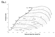
- Figure 1 shows a typical characteristic compressor map in which the pressure ratio is plotted in dependence on the reduced mass flow rate (in m 3 /s). In that respect the efficiency in the normal operating range is well-defined.
- the algorithm according to the invention is implemented by following blocks 220-240.
- block 220 firstly involves calculation of the value J/ 2 (d ⁇ 2 /dt) which in accordance with equation (3) corresponds to the difference between turbine power and compressor power and can thus serve to ascertain a characteristic value for the onset of compressor surge.
- N sample values for the turbocharger speed (TSS value) are put into intermediate storage in accordance with the illustrated embodiment. Then a Fourier transform is performed for those values (function block 231). The value J/2(d ⁇ 2 /dt) is then calculated therefrom in the frequency range or interval [f 1 , f 2 ].
- signal intermediate storage and/or a fast Fourier transform cannot be implemented.
- the signal power calculated in the signal processing block 230 is fed to a function block 240 for the monitor algorithm.
- a characteristic value M[f 1 , f 2 ] in the interval [f 1 , f 2 ] can be ascertained as follows in a block 241:
- a further block 242 involves ascertaining whether the characteristic value exceeds a predetermined limit value, that is to say whether the condition M[f 1 , f 2 ] > M thresh is met. If that is the case a direct flag character 245 or a message about the existence of compressor surge is produced and firstly subjected to checking in a fault diagnosis unit 250.
- the direct flag character 245 is still held or checked for a calibratable period of time for avoidance purposes in the fault diagnosis unit 250 to avoid false readings and is finally output as a confirmed flag character 255 or confirmed message concerning the existence of compressor surge.
Landscapes
- Engineering & Computer Science (AREA)
- Chemical & Material Sciences (AREA)
- Combustion & Propulsion (AREA)
- Mechanical Engineering (AREA)
- General Engineering & Computer Science (AREA)
- Supercharger (AREA)
Abstract
Description
- The present invention concerns a method of and an apparatus for monitoring the operation of an internal combustion engine.
- Turbochargers usually operate both in respect of the compressor and also in respect of the turbine in a well-defined working area which can also be referred to as the characteristic map of the turbocharger. Unstable operation of the turbocharger can lead to a reduction in the service life as well as detrimental effects in terms of driving sensation.
- An unstable flow occurring in the compressor is referred to as compressor pumping (= surge) and is to be attributed to the fact that the current pressure ratio is excessively high for the currently prevailing mass flow value. The range of compressor pumping or surge is characterised by operation with fluctuations in respect of mass flow and pressure, in respect of which a reversed or negative flow can occur. The surge effect leads to a reduction in the performance and the efficiency of the compressor and markedly audible generation of noise and also mechanical malfunctions ultimately leading to damage to the turbocharger itself, which can also result inter alia in warranty claims.
- To reduce surge it is known to introduce calibratable limit curves during engine calibration, which however can lead to an adverse effect on the operating characteristics in the transient mode of operation and in addition is not exact as a consequence of manufacture-induced fluctuations between different hardware components of the turbocharger system.
- Conventionally, to determine whether a surge situation is occurring a corrected MAF value (MAF = mass air flow) is ascertained in dependence on a correct PRC value (PRC = pressure ratio compressor). In addition a mass air flow sensor which is common in the automobile industry can be used to detect the onset of a surge situation and to specify the correct frequency range of the oscillations occurring in the surge situation.
- In that respect however the problem arises that, in accordance with the Euro 6 standard and beyond, replacement of the MAF sensor is planned by virtue of durability problems, in particular in frequent operation in inner city driving conditions. The result of this is that the MAF value is estimated in other ways, for example by means of turbocharger speed sensors, by way of real-time modelling of the induction manifold or by means of methods based on the use of an oxygen sensor.
- A further sensor which is common in the automobile sector is the MAP sensor (= boost pressure sensor) which is normally placed in the intake manifold. The MAP signal is however filtered by the induction manifold, wherein, in the case of an arrangement downstream of the exhaust gas recycling inlet (EGR inlet), the effect is attenuated even more.
- While turbocharger speed sensors (abbreviated as: TSS) for avoiding overspeeding of the turbocharger are already established in commercial vehicles, the introduction of such sensors in the mass production of passenger cars is not yet widespread. Besides the capability of estimating engine parameters such as the pressure upstream of the turbine (also referred to as P3), the temperature at the compressor outlet (also referred to as T2), the temperature at the turbine inlet (also referred to as T3) and the mass air flow (also referred to as the MAF value), turbocharger speed sensors are used for implementing advanced turbocharger control and for diagnostic devices such as for example in multi-turbocharger systems in which damage to a turbine shut-off valve can be detected by way of the secondary turbocharger speed measurement.
- Having regarded to the foregoing background a problem of the present invention is to provide a method and an apparatus for monitoring the operation of an internal combustion engine, which permit quick reliable detection of compressor surge. That problem is solved by the method comprising the features of independent claim 1 and the apparatus comprising the features of claim 7.
- A method according to the invention of monitoring the operation of an internal combustion engine, wherein the internal combustion engine has a turbocharger with a compressor, has the following steps: ascertaining at least one turbocharger speed signal and calculating a characteristic based on the turbocharger speed signal, wherein the existence of a surge of the compressor is established on the basis of said characteristic.
- The invention is based in particular on the concept of using a turbocharger speed sensor to define a characteristic based on the turbocharger speed signal and which in turn can serve as a direct measurement for existing or incipient surge of the compressor. The invention is therefore based in particular on the realisation that compressor surge represents a further property which can be diagnosed by means of the turbocharger speed. As the outcome, the method and the apparatus according to the invention permit more reliable and faster detection of compressor surge.
- In accordance with an embodiment compressor surge is assumed to be "active" if the characteristic based on the turbocharger speed signal exceeds a (preferably) calibratable threshold value for a time period (which is preferably also calibratable).
- In accordance with the invention on the one hand pure monitoring (without implementation of corrective measures) in regard to existing or incipient compressor surge can be effected.
- In accordance with a further aspect, based on the monitoring according to the invention, active control can also be provided to the effect that suitable corrective measures are taken in the event of detection of compressor surge. In particular the reference value for the boost pressure can be reduced when compressor surge is detected.
- In accordance with an embodiment calculation of a characteristic based on the turbocharger speed signal is effected on the basis of the relationship

wherein ω denotes the turbocharger speed, Pt is the turbine power, Pc denotes the compressor power and J denotes the moment of inertia of the whole turbocharger. - According to an embodiment the method further includes the following steps: ascertaining N sample values for the turbocharger speed (TSS value) and calculating the value J/2(dω2/dt) for said sample values. The N sample values can be subjected in particular to a Fourier transform.
- The invention further concerns an apparatus for monitoring the operation of an internal combustion engine. Regarding advantages and preferred configurations of the apparatus attention is directed to the foregoing description relating to the method.
- Further configurations of the invention are to be found in the description and the appendant claims.
- The invention is described in greater detail hereinafter by means of a preferred embodiment by way of example and with reference to the accompanying drawings in which:
- Figure 1
- shows a typical characteristic map of a compressor, in which the pressure ratio is plotted in dependence on the reduced mass flow rate; and
- Figure 2
- shows a flow chart for describing a method in accordance with an embodiment of the invention.
- The following values or abbreviations are used hereinafter:
Tc compressor torque Tt turbine torque Pc compressor power Pt turbine power J moment of inertia of the whole turbocharger (including turbine, compressor and shaft) ω (also: TSS value) turbocharger speed - Hereinafter firstly the underlying mathematical equations of the present invention will be developed:
- The following applies for the relationship between the turbocharger speed, the compressor torque and the turbine torque:

- The following follows therefrom:

- Upon replacement of the torque Tt, Tc of turbine and compressor respectively by the respective power equation (2) gives the following:

-
Figure 1 shows a typical characteristic compressor map in which the pressure ratio is plotted in dependence on the reduced mass flow rate (in m3/s). In that respect the efficiency in the normal operating range is well-defined. - In accordance with the flow chart show shown in
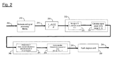
Figure 2 signal processing and filtering of araw signal 205 is firstly effected insuitable hardware 210 in order to ascertain a suitable measurement value in respect of the turbocharger speed sensor signal 215 (for brevity: TSS signal) in revolutions per minute (= rpm). - The algorithm according to the invention is implemented by following blocks 220-240.
- In that respect,
block 220 firstly involves calculation of the value J/2(dω2/dt) which in accordance with equation (3) corresponds to the difference between turbine power and compressor power and can thus serve to ascertain a characteristic value for the onset of compressor surge. - In a subsequent signal processing block 230 N sample values for the turbocharger speed (TSS value) are put into intermediate storage in accordance with the illustrated embodiment. Then a Fourier transform is performed for those values (function block 231). The value J/2(dω2/dt) is then calculated therefrom in the frequency range or interval [f1, f2].
- Depending on the respective application or hardware environment, signal intermediate storage and/or a fast Fourier transform cannot be implemented. In that case it is alternatively also possible to ascertain directly the power difference in the range between the frequencies f1 and f2 (that is to say the range in which compressor surge occurs), in which case that difference can then be filtered.
- The signal power calculated in the
signal processing block 230 is fed to afunction block 240 for the monitor algorithm. Here to detect the presence of compressor surge a characteristic value M[f1, f2] in the interval [f1, f2] can be ascertained as follows in a block 241: - as a statistical mean of the value J/2(dω2/dt) for the sample values in the interval [f1, f2],
- based on the statistical standard deviation of the value J/2(dω2/dt) in the interval [f1, f2], or
- based on the absolute amount of the value J/2(dω2/dt) in the interval [f1, f2].
- A
further block 242 involves ascertaining whether the characteristic value exceeds a predetermined limit value, that is to say whether the condition M[f1, f2] > Mthresh is met. If that is the case adirect flag character 245 or a message about the existence of compressor surge is produced and firstly subjected to checking in afault diagnosis unit 250. - The
direct flag character 245 is still held or checked for a calibratable period of time for avoidance purposes in thefault diagnosis unit 250 to avoid false readings and is finally output as a confirmedflag character 255 or confirmed message concerning the existence of compressor surge. - Overall the method and the apparatus according to the invention permit faster and more reliable detection of compressor surge.
Claims (7)
- A method of monitoring the operation of an internal combustion engine, wherein the internal combustion engine has a turbocharger with a compressor,
characterised in that
the method has the following steps:ascertaining at least one turbocharger speed signal; andcalculating a characteristic based on the turbocharger speed signal,wherein the existence of a surge of the compressor is established on the basis of said characteristic. - A method according to claim 1
characterised in that
for the case where compressor surge is detected a suitable corrective measure is taken to reduce the compressor surge. - A method according to claim 1 or claim 2
characterised in that
compressor surge is detected if said characteristic exceeds a predetermined threshold value for a predetermined period of time. - A method according to one of the preceding claims
characterised in that
calculation of a characteristic based on the turbocharger speed signal is effected on the basis of the relationship
wherein ω denotes the turbocharger speed, Pt is the turbine power, Pc denotes the compressor power and J denotes the moment of inertia of the whole turbocharger. - A method according to claim 4
characterised in that
the method includes the following steps:ascertaining N sample values for the turbocharger speed; andcalculating the value J/2(dω2/dt) for said sample values. - A method according to claim 5
characterised in that
the N sample values are subjected to a Fourier transform. - Apparatus for monitoring the operation of an internal combustion engine, wherein the internal combustion engine has a turbocharger with a compressor,
characterised in that
the apparatus is adapted to carry out a method according to one of the preceding steps.
Priority Applications (1)
| Application Number | Priority Date | Filing Date | Title |
|---|---|---|---|
| EP09168895A EP2295761B1 (en) | 2009-08-28 | 2009-08-28 | Method of and apparatus for monitoring the operation of an internal combustion engine |
Applications Claiming Priority (1)
| Application Number | Priority Date | Filing Date | Title |
|---|---|---|---|
| EP09168895A EP2295761B1 (en) | 2009-08-28 | 2009-08-28 | Method of and apparatus for monitoring the operation of an internal combustion engine |
Publications (2)
| Publication Number | Publication Date |
|---|---|
| EP2295761A1 true EP2295761A1 (en) | 2011-03-16 |
| EP2295761B1 EP2295761B1 (en) | 2012-10-24 |
Family
ID=41508987
Family Applications (1)
| Application Number | Title | Priority Date | Filing Date |
|---|---|---|---|
| EP09168895A Not-in-force EP2295761B1 (en) | 2009-08-28 | 2009-08-28 | Method of and apparatus for monitoring the operation of an internal combustion engine |
Country Status (1)
| Country | Link |
|---|---|
| EP (1) | EP2295761B1 (en) |
Cited By (2)
| Publication number | Priority date | Publication date | Assignee | Title |
|---|---|---|---|---|
| US9989029B2 (en) | 2014-02-04 | 2018-06-05 | Ford Global Technologies, Llc | Method and device for determining a charge air mass flow rate |
| WO2022128672A1 (en) * | 2020-12-15 | 2022-06-23 | Robert Bosch Gmbh | Method for operating a fluid machine, and control unit |
Families Citing this family (1)
| Publication number | Priority date | Publication date | Assignee | Title |
|---|---|---|---|---|
| US20190017452A1 (en) * | 2017-07-12 | 2019-01-17 | GM Global Technology Operations LLC | Air path control for engine assembly with waste-gated turbine |
Citations (4)
| Publication number | Priority date | Publication date | Assignee | Title |
|---|---|---|---|---|
| US20040216457A1 (en) | 2002-10-21 | 2004-11-04 | General Electric Company | Apparatus and method for automatic detection and avoidance of turbocharger surge on locomotive diesel engines |
| US6871498B1 (en) * | 2003-12-20 | 2005-03-29 | Honeywell International, Inc. | Compressor surge protector for electric assisted turbocharger |
| US7089738B1 (en) | 2005-04-09 | 2006-08-15 | Cummins, Inc. | System for controlling turbocharger compressor surge |
| US20070095063A1 (en) * | 2005-11-02 | 2007-05-03 | General Electric Company | Apparatus and method for avoidance of turbocharger surge on locomotive diesel engines |
-
2009
- 2009-08-28 EP EP09168895A patent/EP2295761B1/en not_active Not-in-force
Patent Citations (4)
| Publication number | Priority date | Publication date | Assignee | Title |
|---|---|---|---|---|
| US20040216457A1 (en) | 2002-10-21 | 2004-11-04 | General Electric Company | Apparatus and method for automatic detection and avoidance of turbocharger surge on locomotive diesel engines |
| US6871498B1 (en) * | 2003-12-20 | 2005-03-29 | Honeywell International, Inc. | Compressor surge protector for electric assisted turbocharger |
| US7089738B1 (en) | 2005-04-09 | 2006-08-15 | Cummins, Inc. | System for controlling turbocharger compressor surge |
| US20070095063A1 (en) * | 2005-11-02 | 2007-05-03 | General Electric Company | Apparatus and method for avoidance of turbocharger surge on locomotive diesel engines |
Cited By (2)
| Publication number | Priority date | Publication date | Assignee | Title |
|---|---|---|---|---|
| US9989029B2 (en) | 2014-02-04 | 2018-06-05 | Ford Global Technologies, Llc | Method and device for determining a charge air mass flow rate |
| WO2022128672A1 (en) * | 2020-12-15 | 2022-06-23 | Robert Bosch Gmbh | Method for operating a fluid machine, and control unit |
Also Published As
| Publication number | Publication date |
|---|---|
| EP2295761B1 (en) | 2012-10-24 |
Similar Documents
| Publication | Publication Date | Title |
|---|---|---|
| CN111140385B (en) | A method and system for improving the robustness of a natural gas engine | |
| JP3741290B2 (en) | Pressure sensor fault diagnosis control device | |
| CN110131193B (en) | Method and system for monitoring surge fault of aircraft engine | |
| US7509845B2 (en) | Throttle inlet absolute air pressure sensor for dirty air filter detection | |
| EP2728142B1 (en) | Turbocharger bearing health monitor | |
| EP2392803B1 (en) | Method for determining the rotation speed of a supercharger in an internal combustion engine | |
| JP4876107B2 (en) | Diagnostic control device for internal combustion engine | |
| EP2010777B1 (en) | Control apparatus and control method for internal combustion engine having centrifugal compressor | |
| EP2392804B1 (en) | Method for determining the rotation speed of a supercharger in an internal combustion engine | |
| CN113757000A (en) | Detection method, device, equipment and storage medium of exhaust gas recirculation system | |
| CN101641508A (en) | Forced air induction system for internal combustion engine and abnormality diagnosis method for same system | |
| US11352921B2 (en) | Device and method for diagnosing positive crankcase ventilation breather line | |
| EP2295761B1 (en) | Method of and apparatus for monitoring the operation of an internal combustion engine | |
| JP2013108416A (en) | Intercooler diagnosis system | |
| CN102678330A (en) | Diagnostic method for pressure sensors in turbocharging system | |
| CN113389667B (en) | Performance monitoring and fault diagnosis method for high-pressure EGR cooler | |
| WO2007136449A1 (en) | System and method for monitoring boost leak | |
| CN113027607B (en) | Fault detection method for oil-gas separator and related device | |
| CN119353096B (en) | Method and device for diagnosing rationality of supercharged engine supercharging capacity | |
| GB2558604A (en) | Method to detect faults in boost system of a turbocharged engine | |
| CN117722288A (en) | A fault diagnosis method and related device | |
| EP3064756A1 (en) | Method for estimating pressure loss of air cleaner and device for estimating pressure loss of air cleaner | |
| US9983088B2 (en) | Engine ventilation system diagnostics using pressure measurement | |
| KR102323409B1 (en) | Method and system for diagnosing boost pressure sensor | |
| JP7373380B2 (en) | Humidity sensor diagnostic device and humidity sensor diagnostic method |
Legal Events
| Date | Code | Title | Description |
|---|---|---|---|
| PUAI | Public reference made under article 153(3) epc to a published international application that has entered the european phase |
Free format text: ORIGINAL CODE: 0009012 |
|
| AK | Designated contracting states |
Kind code of ref document: A1 Designated state(s): AT BE BG CH CY CZ DE DK EE ES FI FR GB GR HR HU IE IS IT LI LT LU LV MC MK MT NL NO PL PT RO SE SI SK SM TR |
|
| 17P | Request for examination filed |
Effective date: 20110916 |
|
| 17Q | First examination report despatched |
Effective date: 20111111 |
|
| GRAP | Despatch of communication of intention to grant a patent |
Free format text: ORIGINAL CODE: EPIDOSNIGR1 |
|
| GRAS | Grant fee paid |
Free format text: ORIGINAL CODE: EPIDOSNIGR3 |
|
| GRAA | (expected) grant |
Free format text: ORIGINAL CODE: 0009210 |
|
| AK | Designated contracting states |
Kind code of ref document: B1 Designated state(s): AT BE BG CH CY CZ DE DK EE ES FI FR GB GR HR HU IE IS IT LI LT LU LV MC MK MT NL NO PL PT RO SE SI SK SM TR |
|
| REG | Reference to a national code |
Ref country code: GB Ref legal event code: FG4D |
|
| REG | Reference to a national code |
Ref country code: CH Ref legal event code: EP |
|
| REG | Reference to a national code |
Ref country code: AT Ref legal event code: REF Ref document number: 581087 Country of ref document: AT Kind code of ref document: T Effective date: 20121115 |
|
| REG | Reference to a national code |
Ref country code: IE Ref legal event code: FG4D |
|
| REG | Reference to a national code |
Ref country code: DE Ref legal event code: R096 Ref document number: 602009010596 Country of ref document: DE Effective date: 20121220 |
|
| REG | Reference to a national code |
Ref country code: AT Ref legal event code: MK05 Ref document number: 581087 Country of ref document: AT Kind code of ref document: T Effective date: 20121024 |
|
| REG | Reference to a national code |
Ref country code: NL Ref legal event code: VDEP Effective date: 20121024 |
|
| PG25 | Lapsed in a contracting state [announced via postgrant information from national office to epo] |
Ref country code: IS Free format text: LAPSE BECAUSE OF FAILURE TO SUBMIT A TRANSLATION OF THE DESCRIPTION OR TO PAY THE FEE WITHIN THE PRESCRIBED TIME-LIMIT Effective date: 20130224 Ref country code: ES Free format text: LAPSE BECAUSE OF FAILURE TO SUBMIT A TRANSLATION OF THE DESCRIPTION OR TO PAY THE FEE WITHIN THE PRESCRIBED TIME-LIMIT Effective date: 20130204 Ref country code: HR Free format text: LAPSE BECAUSE OF FAILURE TO SUBMIT A TRANSLATION OF THE DESCRIPTION OR TO PAY THE FEE WITHIN THE PRESCRIBED TIME-LIMIT Effective date: 20121024 Ref country code: FI Free format text: LAPSE BECAUSE OF FAILURE TO SUBMIT A TRANSLATION OF THE DESCRIPTION OR TO PAY THE FEE WITHIN THE PRESCRIBED TIME-LIMIT Effective date: 20121024 Ref country code: SE Free format text: LAPSE BECAUSE OF FAILURE TO SUBMIT A TRANSLATION OF THE DESCRIPTION OR TO PAY THE FEE WITHIN THE PRESCRIBED TIME-LIMIT Effective date: 20121024 Ref country code: NL Free format text: LAPSE BECAUSE OF FAILURE TO SUBMIT A TRANSLATION OF THE DESCRIPTION OR TO PAY THE FEE WITHIN THE PRESCRIBED TIME-LIMIT Effective date: 20121024 Ref country code: NO Free format text: LAPSE BECAUSE OF FAILURE TO SUBMIT A TRANSLATION OF THE DESCRIPTION OR TO PAY THE FEE WITHIN THE PRESCRIBED TIME-LIMIT Effective date: 20130124 |
|
| PG25 | Lapsed in a contracting state [announced via postgrant information from national office to epo] |
Ref country code: LV Free format text: LAPSE BECAUSE OF FAILURE TO SUBMIT A TRANSLATION OF THE DESCRIPTION OR TO PAY THE FEE WITHIN THE PRESCRIBED TIME-LIMIT Effective date: 20121024 Ref country code: SI Free format text: LAPSE BECAUSE OF FAILURE TO SUBMIT A TRANSLATION OF THE DESCRIPTION OR TO PAY THE FEE WITHIN THE PRESCRIBED TIME-LIMIT Effective date: 20121024 Ref country code: PT Free format text: LAPSE BECAUSE OF FAILURE TO SUBMIT A TRANSLATION OF THE DESCRIPTION OR TO PAY THE FEE WITHIN THE PRESCRIBED TIME-LIMIT Effective date: 20130225 Ref country code: PL Free format text: LAPSE BECAUSE OF FAILURE TO SUBMIT A TRANSLATION OF THE DESCRIPTION OR TO PAY THE FEE WITHIN THE PRESCRIBED TIME-LIMIT Effective date: 20121024 Ref country code: BE Free format text: LAPSE BECAUSE OF FAILURE TO SUBMIT A TRANSLATION OF THE DESCRIPTION OR TO PAY THE FEE WITHIN THE PRESCRIBED TIME-LIMIT Effective date: 20121024 Ref country code: GR Free format text: LAPSE BECAUSE OF FAILURE TO SUBMIT A TRANSLATION OF THE DESCRIPTION OR TO PAY THE FEE WITHIN THE PRESCRIBED TIME-LIMIT Effective date: 20130125 |
|
| PG25 | Lapsed in a contracting state [announced via postgrant information from national office to epo] |
Ref country code: AT Free format text: LAPSE BECAUSE OF FAILURE TO SUBMIT A TRANSLATION OF THE DESCRIPTION OR TO PAY THE FEE WITHIN THE PRESCRIBED TIME-LIMIT Effective date: 20121024 |
|
| PG25 | Lapsed in a contracting state [announced via postgrant information from national office to epo] |
Ref country code: DK Free format text: LAPSE BECAUSE OF FAILURE TO SUBMIT A TRANSLATION OF THE DESCRIPTION OR TO PAY THE FEE WITHIN THE PRESCRIBED TIME-LIMIT Effective date: 20121024 Ref country code: SK Free format text: LAPSE BECAUSE OF FAILURE TO SUBMIT A TRANSLATION OF THE DESCRIPTION OR TO PAY THE FEE WITHIN THE PRESCRIBED TIME-LIMIT Effective date: 20121024 Ref country code: BG Free format text: LAPSE BECAUSE OF FAILURE TO SUBMIT A TRANSLATION OF THE DESCRIPTION OR TO PAY THE FEE WITHIN THE PRESCRIBED TIME-LIMIT Effective date: 20130124 Ref country code: EE Free format text: LAPSE BECAUSE OF FAILURE TO SUBMIT A TRANSLATION OF THE DESCRIPTION OR TO PAY THE FEE WITHIN THE PRESCRIBED TIME-LIMIT Effective date: 20121024 Ref country code: CZ Free format text: LAPSE BECAUSE OF FAILURE TO SUBMIT A TRANSLATION OF THE DESCRIPTION OR TO PAY THE FEE WITHIN THE PRESCRIBED TIME-LIMIT Effective date: 20121024 |
|
| PG25 | Lapsed in a contracting state [announced via postgrant information from national office to epo] |
Ref country code: RO Free format text: LAPSE BECAUSE OF FAILURE TO SUBMIT A TRANSLATION OF THE DESCRIPTION OR TO PAY THE FEE WITHIN THE PRESCRIBED TIME-LIMIT Effective date: 20121024 Ref country code: IT Free format text: LAPSE BECAUSE OF FAILURE TO SUBMIT A TRANSLATION OF THE DESCRIPTION OR TO PAY THE FEE WITHIN THE PRESCRIBED TIME-LIMIT Effective date: 20121024 |
|
| PLBE | No opposition filed within time limit |
Free format text: ORIGINAL CODE: 0009261 |
|
| STAA | Information on the status of an ep patent application or granted ep patent |
Free format text: STATUS: NO OPPOSITION FILED WITHIN TIME LIMIT |
|
| 26N | No opposition filed |
Effective date: 20130725 |
|
| REG | Reference to a national code |
Ref country code: DE Ref legal event code: R097 Ref document number: 602009010596 Country of ref document: DE Effective date: 20130725 |
|
| PG25 | Lapsed in a contracting state [announced via postgrant information from national office to epo] |
Ref country code: CY Free format text: LAPSE BECAUSE OF FAILURE TO SUBMIT A TRANSLATION OF THE DESCRIPTION OR TO PAY THE FEE WITHIN THE PRESCRIBED TIME-LIMIT Effective date: 20121024 |
|
| REG | Reference to a national code |
Ref country code: CH Ref legal event code: PL |
|
| PG25 | Lapsed in a contracting state [announced via postgrant information from national office to epo] |
Ref country code: CH Free format text: LAPSE BECAUSE OF NON-PAYMENT OF DUE FEES Effective date: 20130831 Ref country code: MC Free format text: LAPSE BECAUSE OF FAILURE TO SUBMIT A TRANSLATION OF THE DESCRIPTION OR TO PAY THE FEE WITHIN THE PRESCRIBED TIME-LIMIT Effective date: 20121024 Ref country code: LI Free format text: LAPSE BECAUSE OF NON-PAYMENT OF DUE FEES Effective date: 20130831 |
|
| REG | Reference to a national code |
Ref country code: IE Ref legal event code: MM4A |
|
| PG25 | Lapsed in a contracting state [announced via postgrant information from national office to epo] |
Ref country code: LT Free format text: LAPSE BECAUSE OF FAILURE TO SUBMIT A TRANSLATION OF THE DESCRIPTION OR TO PAY THE FEE WITHIN THE PRESCRIBED TIME-LIMIT Effective date: 20121024 Ref country code: IE Free format text: LAPSE BECAUSE OF NON-PAYMENT OF DUE FEES Effective date: 20130828 |
|
| PG25 | Lapsed in a contracting state [announced via postgrant information from national office to epo] |
Ref country code: SM Free format text: LAPSE BECAUSE OF FAILURE TO SUBMIT A TRANSLATION OF THE DESCRIPTION OR TO PAY THE FEE WITHIN THE PRESCRIBED TIME-LIMIT Effective date: 20121024 |
|
| PG25 | Lapsed in a contracting state [announced via postgrant information from national office to epo] |
Ref country code: TR Free format text: LAPSE BECAUSE OF FAILURE TO SUBMIT A TRANSLATION OF THE DESCRIPTION OR TO PAY THE FEE WITHIN THE PRESCRIBED TIME-LIMIT Effective date: 20121024 Ref country code: MT Free format text: LAPSE BECAUSE OF FAILURE TO SUBMIT A TRANSLATION OF THE DESCRIPTION OR TO PAY THE FEE WITHIN THE PRESCRIBED TIME-LIMIT Effective date: 20121024 |
|
| PG25 | Lapsed in a contracting state [announced via postgrant information from national office to epo] |
Ref country code: LU Free format text: LAPSE BECAUSE OF NON-PAYMENT OF DUE FEES Effective date: 20130828 Ref country code: MK Free format text: LAPSE BECAUSE OF FAILURE TO SUBMIT A TRANSLATION OF THE DESCRIPTION OR TO PAY THE FEE WITHIN THE PRESCRIBED TIME-LIMIT Effective date: 20121024 Ref country code: HU Free format text: LAPSE BECAUSE OF FAILURE TO SUBMIT A TRANSLATION OF THE DESCRIPTION OR TO PAY THE FEE WITHIN THE PRESCRIBED TIME-LIMIT; INVALID AB INITIO Effective date: 20090828 |
|
| REG | Reference to a national code |
Ref country code: FR Ref legal event code: PLFP Year of fee payment: 8 |
|
| REG | Reference to a national code |
Ref country code: FR Ref legal event code: PLFP Year of fee payment: 9 |
|
| REG | Reference to a national code |
Ref country code: FR Ref legal event code: PLFP Year of fee payment: 10 |
|
| PGFP | Annual fee paid to national office [announced via postgrant information from national office to epo] |
Ref country code: FR Payment date: 20190717 Year of fee payment: 11 |
|
| PGFP | Annual fee paid to national office [announced via postgrant information from national office to epo] |
Ref country code: GB Payment date: 20190728 Year of fee payment: 11 |
|
| GBPC | Gb: european patent ceased through non-payment of renewal fee |
Effective date: 20200828 |
|
| PG25 | Lapsed in a contracting state [announced via postgrant information from national office to epo] |
Ref country code: FR Free format text: LAPSE BECAUSE OF NON-PAYMENT OF DUE FEES Effective date: 20200831 |
|
| PG25 | Lapsed in a contracting state [announced via postgrant information from national office to epo] |
Ref country code: GB Free format text: LAPSE BECAUSE OF NON-PAYMENT OF DUE FEES Effective date: 20200828 |
|
| PGFP | Annual fee paid to national office [announced via postgrant information from national office to epo] |
Ref country code: DE Payment date: 20220615 Year of fee payment: 14 |
|
| P01 | Opt-out of the competence of the unified patent court (upc) registered |
Effective date: 20230620 |
|
| REG | Reference to a national code |
Ref country code: DE Ref legal event code: R119 Ref document number: 602009010596 Country of ref document: DE |
|
| PG25 | Lapsed in a contracting state [announced via postgrant information from national office to epo] |
Ref country code: DE Free format text: LAPSE BECAUSE OF NON-PAYMENT OF DUE FEES Effective date: 20240301 |