EP2294952B1 - Einrichtung zur Ausgabe von Milch und/oder Milchschaum - Google Patents
Einrichtung zur Ausgabe von Milch und/oder Milchschaum Download PDFInfo
- Publication number
- EP2294952B1 EP2294952B1 EP09170182A EP09170182A EP2294952B1 EP 2294952 B1 EP2294952 B1 EP 2294952B1 EP 09170182 A EP09170182 A EP 09170182A EP 09170182 A EP09170182 A EP 09170182A EP 2294952 B1 EP2294952 B1 EP 2294952B1
- Authority
- EP
- European Patent Office
- Prior art keywords
- line
- milk
- air supply
- pump
- air
- Prior art date
- Legal status (The legal status is an assumption and is not a legal conclusion. Google has not performed a legal analysis and makes no representation as to the accuracy of the status listed.)
- Active
Links
- 239000008267 milk Substances 0.000 title claims description 111
- 210000004080 milk Anatomy 0.000 title claims description 108
- 235000013336 milk Nutrition 0.000 title claims description 108
- 239000006260 foam Substances 0.000 title claims description 44
- 230000001804 emulsifying effect Effects 0.000 claims abstract description 24
- 230000001914 calming effect Effects 0.000 claims description 13
- 239000012459 cleaning agent Substances 0.000 claims description 8
- 238000000605 extraction Methods 0.000 claims description 7
- 239000000203 mixture Substances 0.000 description 10
- 238000004140 cleaning Methods 0.000 description 8
- 239000003599 detergent Substances 0.000 description 8
- 238000009826 distribution Methods 0.000 description 7
- 210000002445 nipple Anatomy 0.000 description 7
- 235000013353 coffee beverage Nutrition 0.000 description 4
- 238000004945 emulsification Methods 0.000 description 4
- 230000001105 regulatory effect Effects 0.000 description 4
- 238000004519 manufacturing process Methods 0.000 description 3
- 239000003995 emulsifying agent Substances 0.000 description 2
- 238000000034 method Methods 0.000 description 2
- XLYOFNOQVPJJNP-UHFFFAOYSA-N water Chemical compound O XLYOFNOQVPJJNP-UHFFFAOYSA-N 0.000 description 2
- 235000015116 cappuccino Nutrition 0.000 description 1
- 238000005266 casting Methods 0.000 description 1
- 230000001276 controlling effect Effects 0.000 description 1
- 230000001419 dependent effect Effects 0.000 description 1
- 230000002572 peristaltic effect Effects 0.000 description 1
- 230000001960 triggered effect Effects 0.000 description 1
- 238000011144 upstream manufacturing Methods 0.000 description 1
Images


Classifications
-
- A—HUMAN NECESSITIES
- A47—FURNITURE; DOMESTIC ARTICLES OR APPLIANCES; COFFEE MILLS; SPICE MILLS; SUCTION CLEANERS IN GENERAL
- A47J—KITCHEN EQUIPMENT; COFFEE MILLS; SPICE MILLS; APPARATUS FOR MAKING BEVERAGES
- A47J31/00—Apparatus for making beverages
- A47J31/44—Parts or details or accessories of beverage-making apparatus
- A47J31/4485—Nozzles dispensing heated and foamed milk, i.e. milk is sucked from a milk container, heated and foamed inside the device, and subsequently dispensed from the nozzle
Definitions
- the present invention relates to a device for dispensing milk and / or milk foam from a container containing milk, which is insertable into a stored in a frame, coolable cabinet, and in which a withdrawal line can be introduced, which via a first line with a outside of the coolable cabinet arranged emulsifying device is connected, in which first line a pump is used to deliver the milk, through which the milk to be dispensed passes into the emulsifying and dispensing unit, in which emulsifying device via a steam line steam is introduced, with which by the Emulsifying device guided milk can be frothed and / or heated.
- Such devices are known in many ways (see US-A-6099878 ), they can be used for example in coffee machines, which can be made on this coffee machine in an optimal way, for example cappuccino coffee.
- milk can also be used to heat milk, and cold milk can also be supplied.
- the object of the present invention is therefore to provide a device which can supply cold milk foam, hot milk foam, hot milk and cold milk in the best possible quality, the reference of all products that can be delivered by this device, referred in dosable quantities should be.
- the solution of this object is achieved in that in the first line between the pump and the Emulgier worn a branch is attached to which a second line is mounted, in which a first throttle valve and a calming section are arranged, which second line opens into the output unit in that in the first line between branching and emulsifying device a first Closing valve and in the second line before the output unit, a second closing valve is arranged, and that in the first conduit and in the second conduit air can be supplied.
- the product to be purchased can be delivered in the best possible quality.
- the hot milk, the cold milk and the warm milk froth are obtained via the emulsifying device
- the cold milk to which air is supplied is passed through a first throttle valve and a calming section, and then enters the dispensing unit.
- the air-milk mixture emulsified into milk foam, the air is still partially present in the milk in the form of large bubbles, only in the calming section emulsifies the air-milk mixture to fine bubble foam in the desired quality.
- the air supply via at least a first air supply line, which is equipped with a second throttle valve, whereby the air supply takes place in the required amount.
- the first air supply line is closable with a third closing valve, thereby the air supply, for example, for the purchase of cold or hot milk, can be prevented.
- the second throttle valve is adjustable, so that the supplied air can be added in the desired amount in order to obtain the desired milk foam can.
- a first air pump is used, whereby the admixed amount of air can be regulated even more optimal.
- the first air supply line opens in front of the pump in the first line, whereby the air to be supplied is sucked by the pump.
- the first air supply line can also open into the first line after the pump, but in this first air supply line but an air pump is required to mix the air in sufficient quantity can.
- a further advantageous embodiment of the invention is that the air supply via the first air supply line or via a second air supply line, which is equipped with a third throttle valve.
- the second air supply line is closable with a fourth closing valve, whereby the supply of air through this second air supply line can be prevented.
- a second air pump is also used in the second air supply line, whereby the amount of air supplied can be mixed under pressure of the milk.
- the second air supply line in front of the pump can open into the first line, but it can also lead into the first line after the pump.
- the second air supply line can also open into the steam line, whereby the air and the water vapor are mixed together with the milk in the emulsifier.
- a further advantageous embodiment of the invention is that the first throttle valve is adjustable, whereby the nature of the cold milk foam can be regulated.
- the calming section is formed from a hose with a predetermined length, in which the air-milk mixture can develop in an optimal manner to fine-bubble foam.
- a detergent line via which a cleaning agent can be fed, opens into the first line in front of the pump, and a fifth closing valve is inserted into the cleaning line. This allows the entire system to be cleaned at certain intervals.
- a sixth closing valve is inserted into the extraction line, whereby the cleaning of the system can be carried out without removing the milk container.
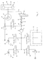
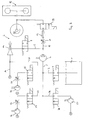
- Fig. 1 schematically a device for dispensing milk and / or milk foam is shown, in which in a known manner not shown, the individual components are inserted in a frame.
- the device comprises a container 1 which is inserted into a refrigerated cabinet 2 shown schematically and which contains cold milk. Inserted into the container 1 is a removal line 3, which can be closed in a known manner via a sixth closing valve 4 is.
- This extraction line 3 opens into a first line 5, which leads the milk taken over the removal line 3 to the container 1 to an emulsifying device 6.
- Inserted into the first line 5 is a pump 7 with which the milk can be conveyed into this emulsifying device 6. Between the pump 7 and the emulsifying device 6, a first closing valve 8 is used, with which the first line can be closed in a known manner.
- a branch 9 is attached between the pump 7 and the first closing valve 8, to which a second line 10 is arranged.
- a first throttle valve 11 and a calming section 12 is attached.
- a second closing valve 13 is inserted into the second line 10, with which this second line 10 can be closed.
- the second line 10 also opens into the dispensing unit 13.
- the emulsifying device 6 is composed of a jet pump 14 and an emulsifying chamber 15.
- the first line 5 opens into this jet pump 14, also in the jet pump 14 opens in a known manner a steam line 16 through which the jet pump 14 steam can be supplied.
- the jet pump 14 is connected to the emulsification chamber 15, the emulsification chamber 15 is connected to the output unit 13.
- This dispensing unit 13 has a distribution vessel 17, which is equipped with two dispensing nipples 18 and 19, so that two vessels can be filled at the same time.
- first air supply line 20 Connected to the first line 5 is a first air supply line 20 and a second air supply line 21.
- the first air supply line 20 is provided with a second throttle valve 22 and a third closing valve 23.
- the second air supply line 21 is provided with a third throttle valve 24 and a fourth closing valve 25.
- this embodiment of the inventive device open the two air supply lines 20 and 21 in front of the pump 7 in the first line. 5
- Fig. 1 shown means cold milk is to be obtained, the sixth closing valve 4 and the first closing valve 8 is opened.
- the third closing valve 23, the fourth closing valve 25, the fifth closing valve 28 and the second closing valve 29 are closed.
- the pump 7 is put into operation, the milk is sucked from the container 1 via the extraction line 3 and the first line 5 and conveyed into the jet pump 14, from where it enters the emulsification chamber 15 and from there into the distribution vessel 17 and through the Dispense nipples 18 and 19 drain into the vessel below.
- the jet pump 14 is supplied with no steam.
- the sixth closing valve 4 and the first closing valve 8 are opened, the third closing valve 23, the fourth closing valve 25, the fifth closing valve 28 and the second closing valve 29 are closed again.
- the pump 7 is turned on, the cold milk is sucked from the container 1 via the extraction line 3 and the first line 5 and conveyed into the jet pump 14, this jet pump 14 is supplied via the steam line 16 steam, the milk is heated, gets into the Emulsifying chamber 15 and from there into the distribution vessel 17 and the output nipple 18 and 19 in the underneath placed vessel.
- the temperature of the hot milk is a function of the amount of steam supplied and the amount of milk delivered by the pump 7. Since the amount of steam is kept approximately constant, the temperature of the hot milk is controlled by the flow rate of the pump.
- the sixth closing valve 4 To produce warm milk foam, the sixth closing valve 4, the first closing valve 8 and the third closing valve 23 are opened.
- the second closing valve 29, the fourth closing valve 25 and the fifth closing valve 28 are closed.
- the pump 7 is switched on, the milk is conveyed to the jet pump 14, at the same time the jet pump 14 is operated with steam and heats the milk.
- the jet pump 14 the air milk mixture is emulsified into warm milk foam.
- the milk foam has large bubbles in the jet pump 14.
- the coarse-bubble frothy milk in that the milk froth enters the emulsifying chamber 15 tangentially, is emulsified into fine foam by rotation in the emulsifying chamber 15 before the milk froth leaves the emulsifying chamber 15 at the bottom.
- This warm milk foam is supplied to the distribution vessel 17 and passes through its output nipple 18 and 19 in the underneath placed vessel.
- the consistency of the warm milk froth is mainly a function of the mixture of milk-air-steam and thus dependent on the air passage through the second throttle valve 22 and the amount of milk delivered by the pump 7.
- the sixth closing valve 4, the second closing valve 29 and the fourth closing valve 25 are opened.
- the first closing valve 8, the third closing valve 23 and the fifth closing valve 28 are closed.
- the milk is sucked by operating the pump 7 via the extraction line 3 in the first line 5.
- Air is sucked in via the second air supply line 21 and admixed with the milk.
- This milk-air mixture is pressed by the first throttle valve 11.
- In this first throttle valve 11 emulsifies the milk-air mixture to milk foam.
- the air is still partially present in the milk in the form of large bubbles.
- This milk-air mixture enters the calming section 12, which consists of a tube 30 having a certain length.
- In this calming section 12 emulsifies the milk-air mixture to fine-bubble foam. This passes via the second line 10 into the distribution vessel 17 and 18 and 19 via the two output nipple in underneath placed vessels.
- the type and consistency of the cold milk foam is a function of the system pressure or the size of the first throttle valve 11, the milk-air mixture or the pumpable amount of the pump 7, the size of the air flow through the third throttle valve 24 and the length and the diameter of the tube 30 of the calming section 12.
- this device for the purchase of these various products is controlled in a known manner via a control unit.
- the bamboos- and the control unit is configured so that, for example, the product choice at the touch of a button, the required Schliessventil thoroughly is set, throttle valves can be preset and adjusted if necessary, the amount of milk can be predetermined, all this can be obtained via a corresponding configuration of the device ,
- the device After purchasing a certain number of selectable products, the device can be cleaned.
- the fifth closing valve 28 and the second closing valve 29 are opened.
- the sixth closing valve 4, the first closing valve 8, the third closing valve 23 and the fourth closing valve 25 are closed.
- cleaning agent pump 27 cleaning agent is conveyed into the first line 5, through the pump 7 into the second line 10 via the detergent line 26, flows through the first throttle valve 11, the calming section 12 and passes through the distribution vessel 17 and the outlet nipples 18 and 19 into one corresponding container. Both hot and cold water can be used for cleaning.
- This Cleaning process can be configured on the device and, for example, automatically triggered after each reference after a certain time.
- the fifth closing valve 28 and the first closing valve 8 is opened.
- the second closing valve 29, the third closing valve 23, the fourth closing valve 25 and the sixth closing valve 4 are closed.
- detergent 27 is introduced into the respective line via the detergent pump 27, passes through the pump 7, the jet pump 14 and the emulsification chamber 15, then passes into the distribution vessel 17 and via the dispensing nipples 18 and 19 into a corresponding vessel.
- 16 steam can be added via the steam line. This cleaning process can be performed automatically.
- the second throttle valve 22 and the third throttle valve 24 can be cleaned, for which the fifth closing valve 28 is opened, also open the third closing valve 23 and the fourth closing valve 25, all other valves are closed, the detergent flows through each of the second Throttle valve 22 and the third throttle valve 24 and respectively enters the schematically illustrated casting 31st
- This device can be designed as an autonomous device, but it can also be integrated into a coffee machine.
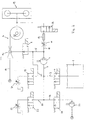
- Fig. 2 shows a device for dispensing milk and / or milk foam, which substantially according to the device Fig. 1 corresponds, the only difference is that the second air supply line 21 opens on the pressure side of the pump 7 in the first line 5, through this second air supply line 21, the required air is sucked in the reference of warm milk foam via the jet pump 14.
- the purchases of the individual products are carried out in an identical manner as in the device according to Fig. 1 , as well as the cleaning.
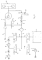
- the decor, as in Fig. 3 is equivalent to that device, such as the Fig. 1 can be removed, the only difference is that in the first air supply line 20 and the second air supply line 21 before the respective throttle valve 22 and 24, an air pump 32 is inserted. As a result, the air can be actively introduced into the first line 5 on the suction side of the pump 7.
- the cleaning of the second throttle valve 22 and the third throttle valve 24 does not have to be done by the cleaning agent, which is supplied via the detergent pump 27. Rather, these two throttle valves 22 and 24 are each cleaned by air surges of the two air pumps 32.
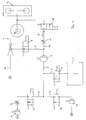
- the device according to Fig. 4 corresponds essentially to the device according to Fig. 3 , the only difference is that the second air supply line 21 after the pump 7, ie on the pressure side, opens into the first line 5.
- the reference of the various products from this device is carried out according to the previously described facilities, the system is cleaned according to the device according to Fig. 3 ,
- the device according to Fig. 5 corresponds essentially to the device according to Fig. 4 However, wherein the first air supply line 20 also opens only after the pump 7, ie on the pressure side, in the first line 5.
- the reference of the individual products remains the same, as in the previously described facilities, the cleaning of the two throttle valves 22 and 24 also takes place via air surges of the corresponding air pumps 32nd
- Fig. 6 shows a device for the purchase of milk and / or milk foam, in which only the first air supply line 20 is provided, which opens into the first line 5 upstream of the pump 7 on the suction side.
- the air pump 32 is attached.
- the reference of the individual products is carried out in the same manner as in the previously described facilities, but in this case the required air for the corresponding products is supplied only through this first air supply line 20, via the air pump 32nd supplied air quantity is electronically controlled, the air pump 32 thus promotes different amounts of air for the production of cold milk foam or of warm milk foam.
- the device for dispensing milk and / or milk foam, as in Fig. 7 is substantially the same as that shown in FIG Fig. 6 , but wherein the first air supply line 20 after the pump 7, that is, on the pressure side, is introduced into the first line 5.
- the operation of this device corresponds to the operation of the device according to Fig. 6 ,
- the device for dispensing milk and / or milk foam, as in Fig. 8 is shown substantially corresponds to the device acc. Fig. 3
- the second air supply line 21 but opens into the steam line 16, and thereby the air for producing warm milk foam in the steam line 16 and from there the jet pump 14 is supplied, so that in a known manner, the milk foam in the emulsifying 6 can be emulsified.
- the reference of the individual products takes place in the same way as in the previously described embodiments.
- Fig. 9 shows a device which is substantially according to those Fig. 8 The only difference is that here the air pump 32 in the first air supply line 20 is omitted, and that in the production of cold milk foam, the required air is sucked in via the pump 7 and mixed with the milk.
- the in the Fig. 1 to 9 shown devices each have six closing valves, which are designed as 2/2-way valves.
- these closing valves are peristaltic pinch valves which allow them to be optimally cleaned; in these valves there are no moving components in the line which could crust with milk and cause problems.
- Commercially available pinch valves are usually suitable only for a pressure of about 0.5 to 1 bar.
- the first closing valve 8 and the second closing valve 29 have to withstand pressures of up to 8 bar. Therefore, motor operated valves are used for these two closing valves.
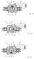
- This two closing valves may be formed, for example, as a combination valve 33, as shown in the Fig. 10-12 is shown.
- This combination valve 33 comprises a housing 34 which has two arcuate receiving areas 35 and 36 for receiving a respective hose 37.
- This hose 37 is preferably a net reinforced hose, whereby a pressure of 8 bar is made possible.
- a rotatable member 38 is mounted between the arcuate portions 35 and 36 and the two tubes 37.
- a closing roller 39 is arranged.
- the rotatable element 38 can be driven via an electric motor 40.
- This rotatable element 38 can be rotated so that the closing roller 39 is located in an arcuate region 35 and squeezes the tube 37 arranged in this arcuate region 35, as shown in FIG Fig. 10 is shown, whereby this hose area is completely closed.
- the rotatable member 38 can be turned into a region between the arcuate portions 35 and 36, as shown in FIG Fig. 11 is shown, characterized both hoses 37, which are located in the respective arcuate portions 35 and 36, opened, the corresponding medium can thus flow through both hoses 37 therethrough.
- the rotatable member 38 can be further rotated until it passes into the other arcuate portion 36, in which a tube 37 is also arranged, as shown in FIG Fig. 12 is shown, the hose 37 of the arcuate portion 36 is thereby squeezed and closed.
- the control of this combination valve 33 in a known manner via the control unit, not shown, for controlling the inventive device. With this combination valve 33 is a achieved perfectly functioning double valve, which can be cleaned in the simplest way, which is suitable for high pressures and easy to operate.
- hot milk, cold milk, hot milk foam and cold milk foam can be made in the optimum desired quality, in particular the warm milk foam and the cold milk foam have the desired consistency.
Description
- Die vorliegende Erfindung bezieht sich auf eine Einrichtung zur Ausgabe von Milch und/oder Milchschaum aus einem Milch enthaltenden Behälter, der in einen in einem Rahmen gehaltenen, kühlbaren Schrank einsetzbar ist, und in welchen eine Entnahmeleitung einbringbar ist, welche über eine erste Leitung mit einer ausserhalb des kühlbaren Schrankes angeordneten Emulgiereinrichtung verbunden ist, in welche erste Leitung eine Pumpe zur Förderung der Milch eingesetzt ist, durch welche die auszugebende Milch in die Emulgiereinrichtung und zur Ausgabeeinheit gelangt, in welche Emulgiereinrichtung über eine Wasserdampfleitung Wasserdampf einführbar ist, mit welchem die durch die Emulgiereinrichtung geleitete Milch aufschäumbar und/oder erwärmbar ist.
- Derartige Einrichtungen sind in vielfacher Weise bekannt (siehe
US-A-6099878 ), sie können beispielsweise in Kaffeemaschinen eingesetzt sein, wodurch über diese Kaffeemaschine in optimaler Weise beispielsweise Cappuccinokaffee hergestellt werden kann. Mit dieser Einrichtung lässt sich neben dem Milchschaum auch Milch erwärmen, es ist auch kalte Milch lieferbar. - Nicht geeignet ist diese Einrichtung zur Herstellung von kaltem Milchschaum, der die gewünschte Qualität aufweist.
- Die Aufgabe der vorliegenden Erfindung besteht somit darin, eine Einrichtung zu schaffen, welche kalten Milchschaum, warmen Milchschaum, heisse Milch und kalte Milch in optimalster Qualität liefern kann, wobei der Bezug aller Produkte, die durch diese Einrichtung ausgeliefert werden können, in dosierbaren Mengen bezogen werden sollen.
- Erfindungsgemäss erfolgt die Lösung dieser Aufgabe dadurch, dass in der ersten Leitung zwischen der Pumpe und der Emulgiereinrichtung eine Abzweigung angebracht ist, an welcher eine zweite Leitung angebracht ist, in welcher ein erstes Drosselventil und eine Beruhigungsstrecke angeordnet sind, welche zweite Leitung in die Ausgabeeinheit mündet, dass in der ersten Leitung zwischen Abzweigung und Emulgiereinrichtung ein erstes Schliessventil und in der zweiten Leitung vor der Ausgabeeinheit ein zweites Schliessventil angeordnet ist, und dass in die erste Leitung und in die zweite Leitung Luft zuführbar ist.
- Mit einer derartigen Einrichtung kann das zu beziehende Produkt in optimalster Qualität geliefert werden. Während die heisse Milch, die kalte Milch und der warme Milchschaum über die Emulgiereinrichtung bezogen werden, wird die kalte Milche, welcher Luft zugeführt wird, durch ein erstes Drosselventil und eine Beruhigungsstrecke geleitet, und gelangt danach in die Ausgabeeinheit. Beim Durchfliessen des Drosselventils emulgiert das Luft-Milch-Gemisch zu Milchschaum, die Luft ist in der Milch teilweise noch in der Form von grossen Blasen vorhanden, erst in der Beruhigungsstrecke emulgiert das Luft-Milch-Gemisch zu feinblasigem Schaum in der gewünschten Qualität.
- In vorteilhafter Weise erfolgt die Luftzuführung über mindestens eine erste Luftzuführungsleitung, welche mit einem zweiten Drosselventil ausgestattet ist, wodurch die Luftzuführung in der erforderlichen Menge erfolgt.
- In vorteilhafter Weise ist die erste Luftzuführungsleitung mit einem dritten Schliessventil verschliessbar, dadurch kann die Luftzuführung, beispielsweise zum Bezug von kalter oder heisser Milch, unterbunden werden.
- In vorteilhafter Weise ist das zweite Drosselventil regulierbar, sodass die zugeführte Luft in der gewünschten Menge beigemischt werden kann, um den gewünschten Milchschaum erhalten zu können.
- In vorteilhafter Weise ist in die erste Luftzuführungsleitung eine erste Luftpumpe eingesetzt, wodurch die beigemischte Luftmenge noch optimaler reguliert werden kann.
- In vorteilhafter Weise mündet die erste Luftzuführungsleitung vor der Pumpe in die erste Leitung, wodurch die zuzuführende Luft von der Pumpe angesaugt wird.
- Die erste Luftzuführungsleitung kann auch nach der Pumpe in die erste Leitung münden, hierzu ist in dieser ersten Luftzuführungsleitung aber eine Luftpumpe erforderlich, um die Luft in genügender Menge beimischen zu können.
- Eine weitere vorteilhafte Ausgestaltung der Erfindung besteht darin, dass die Luftzuführung über die erste Luftzuführungsleitung oder über eine zweite Luftzuführungsleitung erfolgt, welche mit einem dritten Drosselventil ausgestattet ist. Durch diese Anordnung besteht die Möglichkeit, die Luft über die erste Luftzuführungsleitung der Milch beizumischen, welche über die Emulgiereinrichtung geleitet wird, über welche kalte und warme Milch und warmer Milchschaum ausgegeben wird, wobei die Zuführung der Luftmenge konstant gehalten werden kann, während die Fördermenge für die Milch durch die Pumpe geregelt wird. Über die zweite Luftzuführungsleitung wird die Luft der Milch beigemischt, welche durch das erste Drosselventil und die Beruhigungsstrecke zur Ausgabeeinheit geleitet werden, wobei auch hier die Luftzufuhr konstant gehalten werden kann, während die Milchmenge wiederum durch die Pumpe geregelt wird.
- In vorteilhafter Weise ist die zweite Luftzuführungsleitung mit einem vierten Schliessventil verschliessbar, wodurch die Zuführung der Luft durch diese zweite Luftzuführungsleitung unterbunden werden kann.
- In vorteilhafter Weise ist auch in die zweite Luftzuführungsleitung eine zweite Luftpumpe eingesetzt, wodurch die zugeführte Luftmenge unter Druck der Milch beigemischt werden kann.
- Je nach Konfiguration der Anlage kann die zweite Luftzuführungsleitung vor der Pumpe in die erste Leitung münden, sie kann aber auch nach der Pumpe in die erste Leitung münden.
- Die zweite Luftzuführungsleitung kann auch in die Wasserdampfleitung münden, wodurch die Luft und der Wasserdampf gemeinsam der Milch in der Emulgiereinrichtung beigemischt werden.
- Eine weitere vorteilhafte Ausgestaltung der Erfindung besteht darin, dass das erste Drosselventil einstellbar ist, wodurch die Beschaffenheit des kalten Milchschaums reguliert werden kann.
- Eine vorteilhafte Ausgestaltung der Erfindung besteht darin, dass die Beruhigungsstrecke aus einem Schlauch mit einer vorgegebenen Länge gebildet ist, in welchem sich das Luft-Milch-Gemisch in optimaler Weise zu feinblasigem Schaum entwickeln kann.
- In vorteilhafter Weise mündet in die erste Leitung vor der Pumpe eine Reinigungsmittelleitung, über welche ein Reinigungsmittel zuführbar ist, und dass in die Reinigungsmittelleitung ein fünftes Schliessventil eingesetzt ist. Dadurch lässt sich das ganze System in bestimmten Intervallen reinigen.
- In vorteilhafter Weise ist in die Entnahmeleitung ein sechstes Schliessventil eingesetzt, wodurch die Reinigung des Systems ohne Herausnahme des Milchbehälters ausgeführt werden kann.
- Ausführungsformen der Erfindung werden nachfolgend anhand der beiliegenden Zeichnungen beispielhaft näher erläutert.
- Es zeigt
-
Fig. 1 in schematischer Darstellung eine erste Ausführungsform einer erfindungsgemässen Einrichtung zur Ausgabe von Milch und/oder Milchschaum; -
Fig. 2 in schematischer Darstellung eine weitere Ausführungsform einer erfindungsgemässen Einrichtung; -
Fig. 3 in schematischer Darstellung die erfindungsgemässe Einrichtung gemässFig. 1 , mit zusätzlich eingesetzten Luftpumpen; -
Fig. 4 in schematischer Darstellung die Einrichtung gemässFig. 2 mit zusätzlich eingesetzten Luftpumpen; -
Fig. 5 in schematischer Darstellung eine weitere Ausführungsform der erfindungsgemässen Einrichtung zur Ausgabe von Milch und/oder Milchschaum; -
Fig. 6 in schematischer Darstellung eine weitere Ausführungsform der erfindungsgemässen Einrichtung zur Ausgabe von Milch und/oder Milchschaum; -
Fig. 7 in schematischer Darstellung eine Einrichtung entsprechend der Einrichtung gemässFig. 6 , bei welcher aber die Luftzuführung hinter der Pumpe erfolgt; -
Fig. 8 in schematischer Darstellung eine weitere Ausführungsform der erfindungsmässen Einrichtung zur Ausgabe von Milch und/oder Milchschaum; -
Fig. 9 in schematischer Darstellung die Einrichtung gemässFig. 8 , bei welcher aber die Luftpumpe der ersten Luftzuführung weggelassen ist; -
Fig. 10 im Schnitt ein kombiniertes Schlauchquetschventil für zwei Leitungen, bei welcher die obere Leitung gesperrt ist; -
Fig. 11 das Schlauchquetschventil gemässFig. 10 , bei welchem beide Leitungen offen sind; und -
Fig. 12 das Schlauchquetschventil gemässFig. 10 und Fig. 11 , bei welchem die untere Leitung gesperrt ist. - Aus
Fig. 1 ist schematisch eine Einrichtung zur Ausgabe von Milch und/oder Milchschaum dargestellt, bei welcher in bekannter nicht dargestellter Weise die einzelnen Bauteile in einem Rahmen eingesetzt sind. Die Einrichtung weist einen Behälter 1 auf, der in einen im Rahmen gehaltenen schematisch dargestellten kühlbaren Schrank 2 eingesetzt ist und welcher kalte Milch enthält. In den Behälter 1 eingesetzt ist eine Entnahmeleitung 3, welche über ein sechstes Schliessventil 4 in bekannter Weise verschliessbar ist. Diese Entnahmeleitung 3 mündet in eine erste Leitung 5, welche die über die Entnahmeleitung 3 dem Behälter 1 entnommene Milch zu einer Emulgiereinrichtung 6 führt. In die erste Leitung 5 eingesetzt ist eine Pumpe 7, mit welcher die Milch in diese Emulgiereinrichtung 6 gefördert werden kann. Zwischen der Pumpe 7 und der Emulgiereinrichtung 6 ist ein erstes Schliessventil 8 eingesetzt, mit welchem die erste Leitung in bekannter Weise verschliessbar ist. - In der ersten Leitung 5 ist zwischen der Pumpe 7 und dem ersten Schliessventil 8 eine Abzweigung 9 angebracht, an welcher eine zweite Leitung 10 angeordnet ist. In dieser zweiten Leitung 10 ist ein erstes Drosselventil 11 und eine Beruhigungsstrecke 12 angebracht. Hinter der Beruhigungsstrecke 12 ist in die zweite Leitung 10 ein zweites Schliessventil 13 eingesetzt, mit welchem diese zweite Leitung 10 verschliessbar ist. Die zweite Leitung 10 mündet schliesslich ebenfalls in die Ausgabeeinheit 13.
- In bekannter Weise setzt sich die Emulgiereinrichtung 6 aus einer Strahlpumpe 14 und einer Emulgierkammer 15 zusammen. Die erste Leitung 5 mündet in diese Strahlpumpe 14, ebenfalls in die Strahlpumpe 14 mündet in bekannter Weise eine Wasserdampfleitung 16, über welche der Strahlpumpe 14 Wasserdampf zugeführt werden kann. Die Strahlpumpe 14 ist mit der Emulgierkammer 15 verbunden, die Emulgierkammer 15 ist mit der Ausgabeeinheit 13 verbunden.
- Diese Ausgabeeinheit 13 weist ein Verteilgefäss 17 auf, das mit zwei Ausgabenippeln 18 und 19 ausgestattet ist, sodass gleichzeitig auch zwei Gefässe gefüllt werden können.
- An die erste Leitung 5 angeschlossen ist eine erste Luftzuführungsleitung 20 und eine zweite Luftzuführungsleitung 21. Die erste Luftzuführungsleitung 20 ist mit einem zweiten Drosselventil 22 und einem dritten Schliessventil 23 versehen. Die zweite Luftzuführungsleitung 21 ist mit einem dritten Drosselventil 24 und einem vierten Schliessventil 25 versehen. Bei dieser Ausführungsform der erfindungsgemässen Einrichtung münden die beiden Luftzuführungsleitungen 20 und 21 vor der Pumpe 7 in die erste Leitung 5.
- Ebenfalls in die erste Leitung 5 mündet eine Reinigungsmittelleitung 26, in welche eine Reinigungsmittelpumpe 27 und ein fünftes Schliessventil 28 eingesetzt ist.
- Wenn nun mit dieser in
Fig. 1 dargestellten Einrichtung kalte Milch bezogen werden soll, wird das sechste Schliessventil 4 und das erste Schliessventil 8 geöffnet. Das dritte Schliessventil 23, das vierte Schliessventil 25, das fünfte Schliessventil 28 und das zweite Schliessventil 29 sind geschlossen. Die Pumpe 7 wird in Betrieb genommen, die Milch wird aus dem Behälter 1 über die Entnahmeleitung 3 und die erste Leitung 5 angesaugt und in die Strahlpumpe 14 gefördert, von wo sie in die Emulgierkammer 15 und von dort in das Verteilgefäss 17 gelangt und durch die Ausgabenippel 18 und 19 in die darunter gestellten Gefäss ausläuft. Der Strahlpumpe 14 wird kein Dampf zugeführt. - Zur Ausgabe von heisser Milch ist wiederum das sechste Schliessventil 4 und das erste Schliessventil 8 geöffnet, das dritte Schliessventil 23, das vierte Schliessventil 25, das fünfte Schliessventil 28 und das zweite Schliessventil 29 sind wiederum geschlossen. Die Pumpe 7 wird eingeschaltet, die kalte Milch wird aus dem Behälter 1 über die Entnahmeleitung 3 und die erste Leitung 5 angesaugt und in die Strahlpumpe 14 gefördert, dieser Strahlpumpe 14 wird über die Wasserdampfleitung 16 Wasserdampf zugeführt, die Milch wird erhitzt, gelangt in die Emulgierkammer 15 und von dort in das Verteilgefäss 17 und über die Ausgabenippel 18 und 19 in das darunter gestellte Gefäss.
- Die Temperatur der heissen Milch ist eine Funktion der zugeführten Dampfmenge und der durch die Pumpe 7 geförderten Milchmenge. Da die Dampfmenge etwa konstant gehalten wird, wird die Temperatur der heissen Milch über die Fördermenge der Pumpe gesteuert.
- Zur Erzeugung von warmem Milchschaum wird das sechste Schliessventil 4, das erste Schliessventil 8 und das dritte Schliessventil 23 geöffnet. Das zweite Schliessventil 29, das vierte Schliessventil 25 und das fünfte Schliessventil 28 werden geschlossen. Die Pumpe 7 wird eingeschaltet, die Milch wird zur Strahlpumpe 14 gefördert, gleichzeitig wird die Strahlpumpe 14 mit Dampf betrieben und erhitzt die Milch. Auf der Saugseite der Pumpe 7 entsteht in der ersten Leitung 5 ein Unterdruck, über das zweite Drosselventil 22 wird durch die erste Luftzuführungsleitung 20 Luft angesaugt und in der ersten Leitung 5 der Milch beigemischt. In der Strahlpumpe 14 wird das Luftmilchgemisch zu warmem Milchschaum emulgiert.
- Der Milchschaum weist in der Strahlpumpe 14 noch grosse Blasen auf. In der Emulgierkammer 15 wird der grobblasige Milchschaum, indem der Milchschaum tangential in die Emulgierkammer 15 eintritt, durch Rotation in der Emulgierkammer 15, bevor der Milchschaum unten aus der Emulgierkammer 15 austritt, zu feinem Schaum emulgiert. Dieser warme Milchschaum wird dem Verteilgefäss 17 zugeführt und gelangt durch dessen Ausgabenippel 18 und 19 in das darunter gestellte Gefäss.
- Die Konsistenz des warmen Milchschaums ist hauptsächlich eine Funktion des Gemisches Milch-Luft-Dampf und somit abhängig vom Luftdurchlass durch das zweite Drosselventil 22 und der durch die Pumpe 7 geförderten Milchmenge.
- Zur Erzeugung von kaltem Milchschaum ist das sechste Schliessventil 4, das zweite Schliessventil 29 und das vierte Schliessventil 25 geöffnet. Das erste Schliessventil 8, das dritte Schliessventil 23 und das fünfte Schliessventil 28 sind geschlossen. Die Milch wird durch Betätigen der Pumpe 7 über die Entnahmeleitung 3 in die erste Leitung 5 angesaugt. Über die zweite Luftzuführungsleitung 21 wird Luft angesaugt und der Milch zugemischt. Dieses Milch-Luft-Gemisch wird durch das erste Drosselventil 11 gepresst. In diesem ersten Drosselventil 11 emulgiert das Milch-Luft-Gemisch zu Milchschaum. Die Luft ist jedoch in der Milch noch teilweise in Form von grossen Blasen vorhanden. Dieses Milch-Luft-Gemisch gelangt in die Beruhigungsstrecke 12, welche aus einem Schlauch 30 besteht, der eine bestimmte Länge aufweist. In dieser Beruhigungsstrecke 12 emulgiert das Milch-Luft-Gemisch zu feinblasigem Schaum. Dieser gelangt über die zweite Leitung 10 in das Verteilgefäss 17 und über die beiden Ausgabenippel 18 und 19 in darunter gestellte Gefässe.
- Um einen optimalen kalten Milchschaum zu erhalten, muss ein Systemdruck von ca. 8 bar vorhanden sein. Demzufolge muss die entsprechende Systemstrecke entsprechend für diesen Druck ausgelegt sein.
- Die Art und die Konsistenz des kalten Milchschaums ist eine Funktion des Systemdrucks bzw. der Grösse des ersten Drosselventils 11, des Milch-Luft-Gemisches bzw. der förderbaren Menge der Pumpe 7, der Grösse des Luftdurchsatzes durch das dritte Drosselventil 24 sowie der Länge und des Durchmessers des Schlauches 30 der Beruhigungsstrecke 12.
- Selbstverständlich ist diese Einrichtung zum Bezug dieser verschiedenen Produkte in bekannter Weise über eine Steuereinheit gesteuert. Hierbei ist die Einrichtungs- und die Steuereinheit so konfiguriert, dass beispielsweise die Produktewahl über Knopfdruck erfolgt, die erforderliche Schliessventilstellung wird eingestellt, Drosselventile können voreingestellt und gegebenenfalls nachgestellt werden, die Milchmenge kann vorgegeben sein, all dies kann über eine entsprechende Konfiguration der Einrichtung erhalten werden.
- Nach dem Bezug einer bestimmten Anzahl der auswählbaren Produkte kann die Einrichtung gereinigt werden. Zur Reinigung der Strecke "kalter Milchschaum" wird das fünfte Schliessventil 28 und das zweite Schliessventil 29 geöffnet. Das sechste Schliessventil 4, das erste Schliessventil 8, das dritte Schliessventil 23 und das vierte Schliessventil 25 sind geschlossen. Über die Reinigungsmittelpumpe 27 wird über die Reinigungsmittelleitung 26 Reinigungsmittel in die erste Leitung 5, durch die Pumpe 7 in die zweite Leitung 10 gefördert, durchfliesst das erste Drosselventil 11, die Beruhigungsstrecke 12 und gelangt über das Verteilgefäss 17 und die Ausgabenippel 18 und 19 in einen entsprechenden Behälter. Für die Reinigung kann sowohl heisses als auch kaltes Wasser verwendet werden. Dieser Reinigungsvorgang kann an der Einrichtung konfiguriert und beispielsweise nach jedem Bezug nach einer gewissen Zeit automatisch ausgelöst werden.
- Um die Strecke "warmer Milchschaum" bzw. "heisse Milch" reinigen zu können, wird das fünfte Schliessventil 28 und das erste Schliessventil 8 geöffnet. Das zweite Schliessventil 29, das dritte Schliessventil 23, das vierte Schliessventil 25 und das sechste Schliessventil 4 sind geschlossen. Wiederum wird über die Reinigungsmittelpumpe 27 Reinigungsmittel in die jeweilige Leitung eingebracht, durchläuft die Pumpe 7, die Strahlpumpe 14 und die Emulgierkammer 15, gelangt dann in das Verteilgefäss 17 und über die Ausgabenippel 18 und 19 in ein entsprechendes Gefäss. Zusätzlich kann über die Wasserdampfleitung 16 Wasserdampf beigemengt werden. Auch dieser Reinigungsvorgang kann automatisch ausgeführt werden.
- Zusätzlich können auch das zweite Drosselventil 22 und das dritte Drosselventil 24 gereinigt werden, wozu das fünfte Schliessventil 28 geöffnet wird, ebenfalls geöffnet werden das dritte Schliessventil 23 bzw. das vierte Schliessventil 25, sämtliche anderen Ventile sind geschlossen, das Reinigungsmittel durchströmt dadurch jeweils das zweite Drosselventil 22 bzw. das dritte Drosselventil 24 und gelangt jeweils in den schematisch dargestellten Abguss 31.
- Diese Einrichtung kann als autonome Einrichtung ausgebildet sein, sie kann aber auch in eine Kaffeemaschine integriert sein.
-
Fig. 2 zeigt eine Einrichtung zur Ausgabe von Milch und/oder Milchschaum, die im Wesentlichen der Einrichtung gemässFig. 1 entspricht, der einzige Unterschied besteht darin, dass die zweite Luftzuführungsleitung 21 auf der Druckseite der Pumpe 7 in die erste Leitung 5 mündet, durch diese zweite Luftzuführungsleitung 21 wird beim Bezug von warmem Milchschaum über die Strahlpumpe 14 die erforderliche Luft angesaugt. Die Bezüge der einzelnen Produkte erfolgt in identischer Weise, wie bei der Einrichtung gemässFig. 1 , ebenso die Reinigung. - Die Einrichtung, wie sie in
Fig. 3 dargestellt ist, entspricht derjenigen Einrichtung, wie sie derFig. 1 entnehmbar ist, der einzige Unterschied besteht darin, dass in der ersten Luftzuführungsleitung 20 und der zweiten Luftzuführungsleitung 21 vor dem jeweiligen Drosselventil 22 und 24 eine Luftpumpe 32 eingesetzt ist. Dadurch kann die Luft aktiv in die erste Leitung 5 auf der Saugseite der Pumpe 7 eingebracht werden. Die Reinigung des zweiten Drosselventils 22 und des dritten Drosselventils 24 muss hierbei nicht mehr durch das Reinigungsmittel erfolgen, das über die Reinigungsmittelpumpe 27 zugeführt wird. Vielmehr können diese beiden Drosselventile 22 und 24 jeweils durch Luftstösse der beiden Luftpumpen 32 gereinigt werden. - Die Einrichtung gemäss
Fig. 4 entspricht im Wesentlichen der Einrichtung gemässFig. 3 , der einzige Unterschied besteht darin, dass die zweite Luftzuführungsleitung 21 nach der Pumpe 7, also auf deren Druckseite, in die erste Leitung 5 mündet. Der Bezug der verschiedenen Produkte aus dieser Einrichtung erfolgt entsprechend den vorgängig beschriebenen Einrichtungen, gereinigt wird das System entsprechend der Einrichtung gemässFig. 3 . - Die Einrichtung gemäss
Fig. 5 entspricht im Wesentlichen der Einrichtung gemässFig. 4 , wobei aber die erste Luftzuführungsleitung 20 ebenfalls erst nach der Pumpe 7, also auf deren Druckseite, in die erste Leitung 5 mündet. Der Bezug der einzelnen Produkte bleibt sich gleich, wie bei den vorgängig beschriebenen Einrichtungen, die Reinigung der beiden Drosselventile 22 und 24 erfolgt ebenfalls über Luftstösse der entsprechenden Luftpumpen 32. -
Fig. 6 zeigt eine Einrichtung zum Bezug von Milch und/oder Milchschaum, bei welcher nur die erste Luftzuführungsleitung 20 vorgesehen ist, die saugseitig vor der Pumpe 7 in die erste Leitung 5 mündet. Zusätzlich ist die Luftpumpe 32 angebracht. Der Bezug der einzelnen Produkte erfolgt in gleicher Weise wie bei den vorgängig beschriebenen Einrichtungen, hierbei wird aber die erforderliche Luft für die entsprechenden Produkte nur durch diese erste Luftzuführungsleitung 20 zugeführt, die über die Luftpumpe 32 zugeführte Luftmenge wird elektronisch kontrolliert, die Luftpumpe 32 fördert somit für die Erzeugung von kaltem Milchschaum bzw. von warmem Milchschaum unterschiedlich viel Luft. - Die Einrichtung zur Ausgabe von Milch und/oder Milchschaum, wie sie in
Fig. 7 dargestellt ist, entspricht im Wesentlichen derjenigen Einrichtung, dargestellt inFig. 6 , wobei aber die erste Luftzuführungsleitung 20 nach der Pumpe 7, also auf deren Druckseite, in die erste Leitung 5 eingeleitet wird. Die Funktionsweise dieser Einrichtung entspricht der Funktionsweise der Einrichtung gemässFig. 6 . - Die Einrichtung zur Ausgabe von Milch und/oder Milchschaum, wie sie in
Fig. 8 dargestellt ist, entspricht im Wesentlichen der Einrichtung gem.Fig. 3 , wobei die zweite Luftzuführungsleitung 21 aber in die Wasserdampfleitung 16 mündet, und dadurch die Luft zur Herstellung von warmem Milchschaum in die Wasserdampfleitung 16 und von dort der Strahlpumpe 14 zugeführt wird, sodass in bekannter Weise der Milchschaum in der Emulgiereinrichtung 6 emulgiert werden kann. Der Bezug der einzelnen Produkte erfolgt in gleicher Weise, wie bei den vorgängig beschriebenen Ausführungsformen. -
Fig. 9 zeigt eine Einrichtung, die im Wesentlichen derjenigen gemässFig. 8 entspricht, wobei der einzige Unterschied darin besteht, dass hier die Luftpumpe 32 in der ersten Luftzuführungsleitung 20 weggelassen ist, und dass bei der Erzeugung von kaltem Milchschaum die erforderliche Luft über die Pumpe 7 angesaugt und der Milch beigemischt wird. - Die in den
Fig. 1 bis 9 dargestellten Einrichtungen weisen jeweils sechs Schliessventile auf, die als 2/2-Wegeventile ausgebildet sind. In vorteilhafter Weise sind diese Schliessventile Schlauchquetschventile, wodurch diese in optimaler Weise gereinigt werden können, in diesen Ventilen befinden sich keine beweglichen Komponenten in der Leitung, die mit Milch verkrusten und zu Störungen führen könnten. Handelsübliche Schlauchquetschventile sind jedoch meistens nur für einen Druck von ca. 0.5 bis 1 bar geeignet. - Wie bereits vorgängig beschrieben worden ist, müssen das erste Schliessventil 8 und das zweite Schliessventil 29 aber Drücke bis zu 8 bar aushalten. Deshalb werden für diese beiden Schliessventile motorisch betriebenen Ventile eingesetzt.
- Diese beiden Schliessventile können beispielsweise als Kombinationsventil 33 ausgebildet sein, wie dies in den
Fig. 10-12 dargestellt ist. Dieses Kombinationsventil 33 umfasst ein Gehäuse 34, welches zwei bogenförmige Aufnahmebereiche 35 und 36 für die Aufnahme jeweils eines Schlauches 37 aufweist. Dieser Schlauch 37 ist vorzugsweise ein netzverstärkter Schlauch, wodurch eine Druckbeaufschlagung von 8 bar ermöglicht wird. Zwischen den bogenförmigen Bereichen 35 und 36 und den beiden Schläuchen 37 ist ein drehbares Element 38 angebracht. An diesem drehbaren Element ist eine Schliessrolle 39 angeordnet. Das drehbare Element 38 ist über einen Elektromotor 40 antreibbar. - Dieses drehbare Element 38 kann so verdreht werden, dass die Schliessrolle 39 sich im einen bogenförmigen Bereich 35 befindet und den in diesem bogenförmigen Bereich 35 angeordneten Schlauch 37 quetscht, wie dies in
Fig. 10 dargestellt ist, wodurch dieser Schlauchbereich vollständig verschlossen ist. - Das drehbare Element 38 kann in einen Bereich zwischen den bogenförmigen Bereichen 35 und 36 verdreht werden, wie dies in
Fig. 11 dargestellt ist, dadurch sind beide Schläuche 37, die sich in den jeweiligen bogenförmigen Bereichen 35 und 36 befinden, geöffnet, das entsprechende Medium kann somit durch beide Schläuche 37 hindurch fliessen. - Das drehbare Element 38 kann weiter gedreht werden, bis es in den anderen bogenförmigen Bereich 36 gelangt, in dem ebenfalls ein Schlauch 37 angeordnet ist, wie dies in
Fig. 12 dargestellt ist, der Schlauch 37 des bogenförmigen Bereiches 36 wird dadurch zusammengequetscht und verschlossen. Die Steuerung dieses Kombinationsventils 33 erfolgt in bekannter Weise über die nicht dargestellte Steuereinheit zur Steuerung der erfindungsgemässen Einrichtung. Mit diesem Kombinationsventil 33 wird ein optimal funktionierendes Doppelventil erreicht, das in einfachster Weise gereinigt werden kann, das für hohe Drücke geeignet ist und das einfach betätigbar ist. - Mit diesen vorgängig beschriebenen erfindungsgemässen Einrichtungen wird erreicht, dass heisse Milch, kalte Milch, heisser Milchschaum und kalter Milchschaum in der optimalsten gewünschten Qualität gemacht werden kann, wobei insbesondere der warme Milchschaum und der kalte Milchschaum die gewünschte Konsistenz aufweisen.
Claims (17)
- Einrichtung zur Ausgabe von Milch und/oder Milchschaum aus einem Milch enthaltenden Behälter (1), der in einen in einem Rahmen gehaltenen, kühlbaren Schrank (2) einsetzbar ist, und in welchen eine Entnahmeleitung (3) einbringbar ist, welche über eine erste Leitung (5) mit einer ausserhalb des kühlbaren Schrankes (2) angeordneten Emulgiereinrichtung (6) verbunden ist, in welche erste Leitung (5) eine Pumpe (7) zur Förderung der Milch eingesetzt ist, durch welche die auszugebende Milch in die Emulgiereinrichtung (6) und zu einer Ausgabeeinheit (13) gelangt, in welche Emulgiereinrichtung (6) über eine Wasserdampfleitung (16) Wasserdampf einführbar ist, mit welchem die durch die Emulgiereinrichtung (6) geleitete Milch aufschäumbar und/oder erwärmbar ist, dadurch gekennzeichnet, dass in der ersten Leitung (5) zwischen der Pumpe (7) und der Emulgiereinrichtung (6) eine Abzweigung (9) angebracht ist, an welcher eine zweite Leitung (10) angebracht ist, in welcher ein erstes Drosselventil (11) und eine Beruhigungsstrecke (12) angeordnet sind, welche zweite Leitung (10) in die Ausgabeeinheit (13) mündet, dass in der ersten Leitung (5) zwischen Abzweigung (9) und Emulgiereinrichtung (6) ein erstes Schliessventil (8) und in der zweiten Leitung (10) vor der Ausgabeeinheit (13) ein zweites Schliessventil (29) angeordnet ist, und dass in die erste Leitung (5) und in die zweite Leitung (10) Luft zuführbar ist.
- Einrichtung nach Anspruch 1, dadurch gekennzeichnet, dass die Luftzuführung über mindestens eine erste Luftzuführungsleitung (20) erfolgt, welche mit einem zweiten Drosselventil (22) ausgestattet ist.
- Einrichtung nach Anspruch 2, dadurch gekennzeichnet, dass die erste Luftzuführungsleitung (20) mit einem dritten Schliessventil (23) verschliessbar ist.
- Einrichtung nach Anspruch 2 oder 3, dadurch gekennzeichnet, dass das zweite Drosselventil (22) regulierbar ist.
- Einrichtung nach einem der Ansprüche 2 bis 4, dadurch gekennzeichnet, dass in die erste Luftzuführungsleitung (20) eine erste Luftpumpe (32) eingesetzt ist.
- Einrichtung nach einem der Ansprüche 2 bis 5, dadurch gekennzeichnet, dass die erste Luftzuführungsleitung (20) vor der Pumpe (7) in die erste Leitung (5) mündet.
- Einrichtung nach Anspruch 5, dadurch gekennzeichnet, dass die erste Luftzuführungsleitung (20) nach der Pumpe (7) in die erste Leitung (5) mündet.
- Einrichtung nach einem der Ansprüche 2 bis 7, dadurch gekennzeichnet, dass die Luftzuführung über die erste Luftzuführungsleitung (20) oder eine zweite Luftzuführungsleitung (21) erfolgt, welche mit einem dritten Drosselventil (24) ausgestattet ist.
- Einrichtung nach Anspruch 8, dadurch gekennzeichnet, dass die zweite Luftzuführungsleitung (21) mit einem vierten Schliessventil (25) verschliessbar ist.
- Einrichtung nach Anspruch 8 oder 9, dadurch gekennzeichnet, dass in die zweite Luftzuführungsleitung (21) eine zweite Luftpumpe (32) eingesetzt ist.
- Einrichtung nach einem der Ansprüche 8 bis 10, dadurch gekennzeichnet, dass die zweite Luftzuführungsleitung (21) vor der Pumpe (7) in die erste Leitung (5) mündet.
- Einrichtung nach Anspruch 10, dadurch gekennzeichnet, dass die zweite Luftzuführungsleitung (21) nach der Pumpe (7) in die erste Leitung (5) mündet.
- Einrichtung nach einem der Ansprüche 8 bis 10, dadurch gekennzeichnet, dass die zweite Luftzuführungsleitung (21) in die Wasserdampfleitung (16) mündet.
- Einrichtung nach einem der Ansprüche 1 bis 13, dadurch gekennzeichnet, dass das erste Drosselventil (11) einstellbar ist.
- Einrichtung nach einem der Ansprüche 1 bis 14, dadurch gekennzeichnet, dass die Beruhigungsstrecke (12) aus einem Schlauch (30) mit einer vorgegebenen Länge gebildet ist.
- Einrichtung nach einem der Ansprüche 1 bis 15, dadurch gekennzeichnet, dass in die erste Leitung (5) vor der Pumpe (7) eine Reinigungsmittelleitung (26) mündet, über welche ein Reinigungsmittel zuführbar ist, und dass in die Reinigungsmittelleitung (26) ein fünftes Schliessventil (28) eingesetzt ist.
- Einrichtung nach einem der Ansprüche 1 bis 16, dadurch gekennzeichnet, dass in die Entnahmeleitung (3) ein sechstes Schliessventil (4) eingesetzt ist.
Priority Applications (4)
| Application Number | Priority Date | Filing Date | Title |
|---|---|---|---|
| ES09170182T ES2379678T3 (es) | 2009-09-14 | 2009-09-14 | Dispositivo para dispensar leche y/o espuma de leche |
| AT09170182T ATE538701T1 (de) | 2009-09-14 | 2009-09-14 | Einrichtung zur ausgabe von milch und/oder milchschaum |
| DK09170182.1T DK2294952T3 (da) | 2009-09-14 | 2009-09-14 | Indretning til udskænkning af mælk og/eller mælkeskum |
| EP09170182A EP2294952B1 (de) | 2009-09-14 | 2009-09-14 | Einrichtung zur Ausgabe von Milch und/oder Milchschaum |
Applications Claiming Priority (1)
| Application Number | Priority Date | Filing Date | Title |
|---|---|---|---|
| EP09170182A EP2294952B1 (de) | 2009-09-14 | 2009-09-14 | Einrichtung zur Ausgabe von Milch und/oder Milchschaum |
Publications (2)
| Publication Number | Publication Date |
|---|---|
| EP2294952A1 EP2294952A1 (de) | 2011-03-16 |
| EP2294952B1 true EP2294952B1 (de) | 2011-12-28 |
Family
ID=41491486
Family Applications (1)
| Application Number | Title | Priority Date | Filing Date |
|---|---|---|---|
| EP09170182A Active EP2294952B1 (de) | 2009-09-14 | 2009-09-14 | Einrichtung zur Ausgabe von Milch und/oder Milchschaum |
Country Status (4)
| Country | Link |
|---|---|
| EP (1) | EP2294952B1 (de) |
| AT (1) | ATE538701T1 (de) |
| DK (1) | DK2294952T3 (de) |
| ES (1) | ES2379678T3 (de) |
Cited By (5)
| Publication number | Priority date | Publication date | Assignee | Title |
|---|---|---|---|---|
| EP2695559A1 (de) * | 2012-08-08 | 2014-02-12 | BSH Bosch und Siemens Hausgeräte GmbH | Kaffeevollautomat |
| DE102013224786B3 (de) * | 2013-12-03 | 2015-03-12 | Wmf Ag | Milchaufschäumvorrichtung mit dynamischer Mischeinheit und Getränkebereiter enthaltend dieselbe |
| US9381473B2 (en) | 2011-05-20 | 2016-07-05 | WMF Württembergische Metallwarenfabrik Aktiengesellschaft | Device for foaming milk, beverage maker comprising said device, and method for foaming milk |
| WO2016142318A1 (de) | 2015-03-10 | 2016-09-15 | Wmf Group Gmbh | Milchaufschäumvorrichtung, diese enthaltender getränkebereiter und verfahren zur aufschäumung von milch |
| WO2022253853A1 (de) | 2021-06-02 | 2022-12-08 | Wmf Gmbh | Aufschäumeinheit zum aufschäumen von milch oder milch/luft-gemischen sowie diese enthaltender getränkebereiter |
Families Citing this family (10)
| Publication number | Priority date | Publication date | Assignee | Title |
|---|---|---|---|---|
| DE102011084901A1 (de) | 2011-10-20 | 2013-04-25 | Franke Kaffeemaschinen Ag | Vorrichtung zur Ausgabe von Milch und Verfahren zum Erwärmen von Milch |
| DE202012009074U1 (de) * | 2012-09-21 | 2012-11-08 | Eugster/Frismag Ag | Vorrichtung zur Bereitung von wahlweise kaltem oder warmem Milchschaum oder Abgabe wahlweise kalter oder warmer Milch |
| DE102013224747A1 (de) | 2013-12-03 | 2015-06-03 | Wmf Ag | Durchlauferhitzer, Milchaufschäumer mit Durchlauferhitzer oder Kaffeemaschinen mit Durchlauferhitzer |
| DE102013224750A1 (de) | 2013-12-03 | 2015-06-03 | Wmf Ag | Durchlauferhitzer, Milchaufschäumer mit Durchlauferhitzer und Kaffeemaschine mit Durchlauferhitzer |
| DE202014103825U1 (de) * | 2014-08-18 | 2015-11-23 | Eugster/Frismag Ag | Getränkezubereitungsvorrichtung |
| DE102014112178A1 (de) * | 2014-08-26 | 2016-03-03 | Melitta Professional Coffee Solutions GmbH & Co. KG | Vorrichtung und Verfahren zum Erzeugen von Milchschaum |
| DE102014119062A1 (de) * | 2014-12-18 | 2016-06-23 | Melitta Professional Coffee Solutions GmbH & Co. KG | Vorrichtung und Verfahren zum Erzeugen von Milchschaum |
| NL2016400B1 (en) * | 2016-03-09 | 2017-09-26 | Douwe Egberts Bv | Assembly and method for frothing milk. |
| WO2019077576A1 (en) * | 2017-10-19 | 2019-04-25 | Carimali S.P.A. Con Socio Unico | AUTOMATIC BEVERAGE DISPENSER |
| CH719060A1 (de) * | 2021-10-14 | 2023-04-28 | Steiner Ag Weggis | Verfahren und Einrichtung zur Erzeugung von geschäumten Getränken. |
Family Cites Families (3)
| Publication number | Priority date | Publication date | Assignee | Title |
|---|---|---|---|---|
| IT1177590B (it) * | 1984-03-08 | 1987-08-26 | Mario Chiaro | Dispositivo per la preparazione di latte caldo schiumoso |
| US6019032A (en) * | 1998-10-30 | 2000-02-01 | Acorto, Inc. | Automated espresso and milk aeration apparatus and method |
| US8357416B2 (en) * | 2007-01-09 | 2013-01-22 | Steiner Weggis Ag | Method and apparatus for the production of milk foam or milk-based drinks |
-
2009
- 2009-09-14 ES ES09170182T patent/ES2379678T3/es active Active
- 2009-09-14 AT AT09170182T patent/ATE538701T1/de active
- 2009-09-14 EP EP09170182A patent/EP2294952B1/de active Active
- 2009-09-14 DK DK09170182.1T patent/DK2294952T3/da active
Cited By (9)
| Publication number | Priority date | Publication date | Assignee | Title |
|---|---|---|---|---|
| US9381473B2 (en) | 2011-05-20 | 2016-07-05 | WMF Württembergische Metallwarenfabrik Aktiengesellschaft | Device for foaming milk, beverage maker comprising said device, and method for foaming milk |
| EP2695559A1 (de) * | 2012-08-08 | 2014-02-12 | BSH Bosch und Siemens Hausgeräte GmbH | Kaffeevollautomat |
| DE102012214104A1 (de) * | 2012-08-08 | 2014-02-13 | BSH Bosch und Siemens Hausgeräte GmbH | Kaffeevollautomat |
| DE102013224786B3 (de) * | 2013-12-03 | 2015-03-12 | Wmf Ag | Milchaufschäumvorrichtung mit dynamischer Mischeinheit und Getränkebereiter enthaltend dieselbe |
| WO2016142318A1 (de) | 2015-03-10 | 2016-09-15 | Wmf Group Gmbh | Milchaufschäumvorrichtung, diese enthaltender getränkebereiter und verfahren zur aufschäumung von milch |
| DE102015204278A1 (de) | 2015-03-10 | 2016-09-15 | Wmf Group Gmbh | Milchaufschäumvorrichtung, diese enthaltender Getränkebereiter und Verfahren zur Aufschäumung von Milch |
| US10667645B2 (en) | 2015-03-10 | 2020-06-02 | Wmf Group Gmbh | Milk-frothing device, drinks preparer comprising same, and method for frothing milk |
| WO2022253853A1 (de) | 2021-06-02 | 2022-12-08 | Wmf Gmbh | Aufschäumeinheit zum aufschäumen von milch oder milch/luft-gemischen sowie diese enthaltender getränkebereiter |
| DE102021205640A1 (de) | 2021-06-02 | 2022-12-08 | Wmf Gmbh | Aufschäumeinheit zum Aufschäumen von Milch oder Milch/Luft-Gemischen sowie diese enthaltender Getränkebereiter |
Also Published As
| Publication number | Publication date |
|---|---|
| DK2294952T3 (da) | 2012-04-10 |
| ES2379678T3 (es) | 2012-04-30 |
| EP2294952A1 (de) | 2011-03-16 |
| ATE538701T1 (de) | 2012-01-15 |
Similar Documents
| Publication | Publication Date | Title |
|---|---|---|
| EP2294952B1 (de) | Einrichtung zur Ausgabe von Milch und/oder Milchschaum | |
| EP2534986B1 (de) | Vorrichtung zum Erhitzen und Aufschäumen eines Getränkeprodukts | |
| EP2011421B1 (de) | Vorrichtung zur Ausgabe von auf Milch basierenden Getränken | |
| EP2583596B1 (de) | Vorrichtung zur Ausgabe von Milch und Verfahren zum Erwärmen von Milch | |
| EP2798989B1 (de) | Getränkezubereitungsvorrichtung mit Mitteln zur Milcherhitzung sowie Betriebsverfahren | |
| EP2367465B1 (de) | Kaffeemaschine | |
| EP2869742B1 (de) | System zur zubereitung von milch bzw. milchschaum in getränkeautomaten sowie eine erhitzereinheit | |
| EP1561407B1 (de) | Vorrichtung zur Erzeugung von Milchschaum | |
| EP2878241B1 (de) | Elektrisch betriebener Getränkebereiter, insbesondere elektrisch betriebene Kaffeemaschine, mit Dampflanze zum Milchaufschäumen | |
| EP3273828B1 (de) | Verfahren und dampflanze zum erzeugen insbesondere von milchschaum | |
| EP3500141B1 (de) | Brühvorrichtung zum zubereiten eines heissgetränks und zugehöriges verfahren | |
| EP3181021B1 (de) | Verfahren und vorrichtung zum erzeugen von milchschaum | |
| EP2897506B1 (de) | Vorrichtung zur bereitung von wahlweise kaltem oder warmem milchschaum oder abgabe wahlweise kalter oder warmer milch | |
| EP1472963A1 (de) | Einrichtung zur Ausgabe von Milch und/oder Milchschaum | |
| DE102011102734A1 (de) | Vorrichtung zum Aufschäumen von Milch, Getränkebereiter mit dieser Vorrichtung und Verfahren zum Aufschäumen von Milch | |
| DE60118174T2 (de) | Vorrichtung zum aufschaümen und erhitzen von flüssigkeiten, insbesondere milch | |
| EP3023037B1 (de) | Vorrichtung und verfahren zum erzeugen von milchschaum | |
| DE202009007946U1 (de) | Vorrichtung, die zum Schaumigschlagen von Milch geeignet ist | |
| DE102009013937A1 (de) | Aufschäumvorrichtung | |
| EP2215942A1 (de) | Vorrichtung zum Fördern von Milch | |
| EP2695559A1 (de) | Kaffeevollautomat | |
| EP3210505A1 (de) | Erhitzereinheit für eine vorrichtung zur erhitzung und/oder aufschäumung von milch | |
| EP2988635B1 (de) | Verfahren zum zubereiten eines mischgetränkes sowie getränkeautomat zur durchführung des verfahrens | |
| EP3628193B1 (de) | Getränkezubereitungsvorrichtung mit strahlpumpen | |
| WO2007095770A1 (de) | Vorrichtung zum wärmen und aufschäumen von flüssigkeiten |
Legal Events
| Date | Code | Title | Description |
|---|---|---|---|
| PUAI | Public reference made under article 153(3) epc to a published international application that has entered the european phase |
Free format text: ORIGINAL CODE: 0009012 |
|
| AK | Designated contracting states |
Kind code of ref document: A1 Designated state(s): AT BE BG CH CY CZ DE DK EE ES FI FR GB GR HR HU IE IS IT LI LT LU LV MC MK MT NL NO PL PT RO SE SI SK SM TR |
|
| AX | Request for extension of the european patent |
Extension state: AL BA RS |
|
| GRAP | Despatch of communication of intention to grant a patent |
Free format text: ORIGINAL CODE: EPIDOSNIGR1 |
|
| 17P | Request for examination filed |
Effective date: 20110517 |
|
| GRAS | Grant fee paid |
Free format text: ORIGINAL CODE: EPIDOSNIGR3 |
|
| GRAA | (expected) grant |
Free format text: ORIGINAL CODE: 0009210 |
|
| AK | Designated contracting states |
Kind code of ref document: B1 Designated state(s): AT BE BG CH CY CZ DE DK EE ES FI FR GB GR HR HU IE IS IT LI LT LU LV MC MK MT NL NO PL PT RO SE SI SK SM TR |
|
| REG | Reference to a national code |
Ref country code: GB Ref legal event code: FG4D Free format text: NOT ENGLISH |
|
| REG | Reference to a national code |
Ref country code: CH Ref legal event code: EP |
|
| REG | Reference to a national code |
Ref country code: AT Ref legal event code: REF Ref document number: 538701 Country of ref document: AT Kind code of ref document: T Effective date: 20120115 |
|
| REG | Reference to a national code |
Ref country code: IE Ref legal event code: FG4D |
|
| REG | Reference to a national code |
Ref country code: CH Ref legal event code: NV Representative=s name: BOVARD AG |
|
| REG | Reference to a national code |
Ref country code: DE Ref legal event code: R096 Ref document number: 502009002297 Country of ref document: DE Effective date: 20120301 |
|
| REG | Reference to a national code |
Ref country code: NL Ref legal event code: T3 |
|
| REG | Reference to a national code |
Ref country code: DK Ref legal event code: T3 |
|
| REG | Reference to a national code |
Ref country code: SE Ref legal event code: TRGR |
|
| PG25 | Lapsed in a contracting state [announced via postgrant information from national office to epo] |
Ref country code: LT Free format text: LAPSE BECAUSE OF FAILURE TO SUBMIT A TRANSLATION OF THE DESCRIPTION OR TO PAY THE FEE WITHIN THE PRESCRIBED TIME-LIMIT Effective date: 20111228 Ref country code: NO Free format text: LAPSE BECAUSE OF FAILURE TO SUBMIT A TRANSLATION OF THE DESCRIPTION OR TO PAY THE FEE WITHIN THE PRESCRIBED TIME-LIMIT Effective date: 20120328 |
|
| REG | Reference to a national code |
Ref country code: ES Ref legal event code: FG2A Ref document number: 2379678 Country of ref document: ES Kind code of ref document: T3 Effective date: 20120430 |
|
| LTIE | Lt: invalidation of european patent or patent extension |
Effective date: 20111228 |
|
| PG25 | Lapsed in a contracting state [announced via postgrant information from national office to epo] |
Ref country code: SI Free format text: LAPSE BECAUSE OF FAILURE TO SUBMIT A TRANSLATION OF THE DESCRIPTION OR TO PAY THE FEE WITHIN THE PRESCRIBED TIME-LIMIT Effective date: 20111228 Ref country code: LV Free format text: LAPSE BECAUSE OF FAILURE TO SUBMIT A TRANSLATION OF THE DESCRIPTION OR TO PAY THE FEE WITHIN THE PRESCRIBED TIME-LIMIT Effective date: 20111228 Ref country code: HR Free format text: LAPSE BECAUSE OF FAILURE TO SUBMIT A TRANSLATION OF THE DESCRIPTION OR TO PAY THE FEE WITHIN THE PRESCRIBED TIME-LIMIT Effective date: 20111228 Ref country code: GR Free format text: LAPSE BECAUSE OF FAILURE TO SUBMIT A TRANSLATION OF THE DESCRIPTION OR TO PAY THE FEE WITHIN THE PRESCRIBED TIME-LIMIT Effective date: 20120329 |
|
| PG25 | Lapsed in a contracting state [announced via postgrant information from national office to epo] |
Ref country code: CY Free format text: LAPSE BECAUSE OF FAILURE TO SUBMIT A TRANSLATION OF THE DESCRIPTION OR TO PAY THE FEE WITHIN THE PRESCRIBED TIME-LIMIT Effective date: 20111228 |
|
| REG | Reference to a national code |
Ref country code: IE Ref legal event code: FD4D |
|
| PG25 | Lapsed in a contracting state [announced via postgrant information from national office to epo] |
Ref country code: CZ Free format text: LAPSE BECAUSE OF FAILURE TO SUBMIT A TRANSLATION OF THE DESCRIPTION OR TO PAY THE FEE WITHIN THE PRESCRIBED TIME-LIMIT Effective date: 20111228 Ref country code: SK Free format text: LAPSE BECAUSE OF FAILURE TO SUBMIT A TRANSLATION OF THE DESCRIPTION OR TO PAY THE FEE WITHIN THE PRESCRIBED TIME-LIMIT Effective date: 20111228 Ref country code: EE Free format text: LAPSE BECAUSE OF FAILURE TO SUBMIT A TRANSLATION OF THE DESCRIPTION OR TO PAY THE FEE WITHIN THE PRESCRIBED TIME-LIMIT Effective date: 20111228 Ref country code: IS Free format text: LAPSE BECAUSE OF FAILURE TO SUBMIT A TRANSLATION OF THE DESCRIPTION OR TO PAY THE FEE WITHIN THE PRESCRIBED TIME-LIMIT Effective date: 20120428 Ref country code: BG Free format text: LAPSE BECAUSE OF FAILURE TO SUBMIT A TRANSLATION OF THE DESCRIPTION OR TO PAY THE FEE WITHIN THE PRESCRIBED TIME-LIMIT Effective date: 20120328 Ref country code: IE Free format text: LAPSE BECAUSE OF FAILURE TO SUBMIT A TRANSLATION OF THE DESCRIPTION OR TO PAY THE FEE WITHIN THE PRESCRIBED TIME-LIMIT Effective date: 20111228 |
|
| REG | Reference to a national code |
Ref country code: CH Ref legal event code: NV Representative=s name: RENTSCH PARTNER AG |
|
| PG25 | Lapsed in a contracting state [announced via postgrant information from national office to epo] |
Ref country code: PL Free format text: LAPSE BECAUSE OF FAILURE TO SUBMIT A TRANSLATION OF THE DESCRIPTION OR TO PAY THE FEE WITHIN THE PRESCRIBED TIME-LIMIT Effective date: 20111228 Ref country code: PT Free format text: LAPSE BECAUSE OF FAILURE TO SUBMIT A TRANSLATION OF THE DESCRIPTION OR TO PAY THE FEE WITHIN THE PRESCRIBED TIME-LIMIT Effective date: 20120430 Ref country code: RO Free format text: LAPSE BECAUSE OF FAILURE TO SUBMIT A TRANSLATION OF THE DESCRIPTION OR TO PAY THE FEE WITHIN THE PRESCRIBED TIME-LIMIT Effective date: 20111228 |
|
| PLBE | No opposition filed within time limit |
Free format text: ORIGINAL CODE: 0009261 |
|
| STAA | Information on the status of an ep patent application or granted ep patent |
Free format text: STATUS: NO OPPOSITION FILED WITHIN TIME LIMIT |
|
| 26N | No opposition filed |
Effective date: 20121001 |
|
| REG | Reference to a national code |
Ref country code: DE Ref legal event code: R097 Ref document number: 502009002297 Country of ref document: DE Effective date: 20121001 |
|
| BERE | Be: lapsed |
Owner name: SCHAERER A.G. Effective date: 20120930 |
|
| PG25 | Lapsed in a contracting state [announced via postgrant information from national office to epo] |
Ref country code: MC Free format text: LAPSE BECAUSE OF NON-PAYMENT OF DUE FEES Effective date: 20120930 |
|
| PG25 | Lapsed in a contracting state [announced via postgrant information from national office to epo] |
Ref country code: FI Free format text: LAPSE BECAUSE OF FAILURE TO SUBMIT A TRANSLATION OF THE DESCRIPTION OR TO PAY THE FEE WITHIN THE PRESCRIBED TIME-LIMIT Effective date: 20111228 |
|
| REG | Reference to a national code |
Ref country code: FR Ref legal event code: ST Effective date: 20130531 |
|
| PG25 | Lapsed in a contracting state [announced via postgrant information from national office to epo] |
Ref country code: BE Free format text: LAPSE BECAUSE OF NON-PAYMENT OF DUE FEES Effective date: 20120930 |
|
| PG25 | Lapsed in a contracting state [announced via postgrant information from national office to epo] |
Ref country code: FR Free format text: LAPSE BECAUSE OF NON-PAYMENT OF DUE FEES Effective date: 20121001 |
|
| PG25 | Lapsed in a contracting state [announced via postgrant information from national office to epo] |
Ref country code: MT Free format text: LAPSE BECAUSE OF FAILURE TO SUBMIT A TRANSLATION OF THE DESCRIPTION OR TO PAY THE FEE WITHIN THE PRESCRIBED TIME-LIMIT Effective date: 20111228 |
|
| PG25 | Lapsed in a contracting state [announced via postgrant information from national office to epo] |
Ref country code: TR Free format text: LAPSE BECAUSE OF FAILURE TO SUBMIT A TRANSLATION OF THE DESCRIPTION OR TO PAY THE FEE WITHIN THE PRESCRIBED TIME-LIMIT Effective date: 20111228 |
|
| PG25 | Lapsed in a contracting state [announced via postgrant information from national office to epo] |
Ref country code: LU Free format text: LAPSE BECAUSE OF NON-PAYMENT OF DUE FEES Effective date: 20120914 Ref country code: SM Free format text: LAPSE BECAUSE OF FAILURE TO SUBMIT A TRANSLATION OF THE DESCRIPTION OR TO PAY THE FEE WITHIN THE PRESCRIBED TIME-LIMIT Effective date: 20111228 |
|
| PG25 | Lapsed in a contracting state [announced via postgrant information from national office to epo] |
Ref country code: HU Free format text: LAPSE BECAUSE OF FAILURE TO SUBMIT A TRANSLATION OF THE DESCRIPTION OR TO PAY THE FEE WITHIN THE PRESCRIBED TIME-LIMIT Effective date: 20090914 |
|
| PG25 | Lapsed in a contracting state [announced via postgrant information from national office to epo] |
Ref country code: MK Free format text: LAPSE BECAUSE OF FAILURE TO SUBMIT A TRANSLATION OF THE DESCRIPTION OR TO PAY THE FEE WITHIN THE PRESCRIBED TIME-LIMIT Effective date: 20111228 |
|
| REG | Reference to a national code |
Ref country code: AT Ref legal event code: MM01 Ref document number: 538701 Country of ref document: AT Kind code of ref document: T Effective date: 20140914 |
|
| PG25 | Lapsed in a contracting state [announced via postgrant information from national office to epo] |
Ref country code: AT Free format text: LAPSE BECAUSE OF NON-PAYMENT OF DUE FEES Effective date: 20140914 |
|
| PGFP | Annual fee paid to national office [announced via postgrant information from national office to epo] |
Ref country code: DK Payment date: 20160920 Year of fee payment: 8 |
|
| PGFP | Annual fee paid to national office [announced via postgrant information from national office to epo] |
Ref country code: SE Payment date: 20160920 Year of fee payment: 8 |
|
| PGFP | Annual fee paid to national office [announced via postgrant information from national office to epo] |
Ref country code: ES Payment date: 20160916 Year of fee payment: 8 |
|
| REG | Reference to a national code |
Ref country code: CH Ref legal event code: NV Representative=s name: CMSRK RENTSCH KAELIN AG, CH |
|
| REG | Reference to a national code |
Ref country code: CH Ref legal event code: PFA Owner name: SCHAERER AG, CH Free format text: FORMER OWNER: SCHAERER AG, CH |
|
| REG | Reference to a national code |
Ref country code: CH Ref legal event code: PCAR Free format text: NEW ADDRESS: HIRSCHENGRABEN 1, 8001 ZUERICH (CH) |
|
| REG | Reference to a national code |
Ref country code: DK Ref legal event code: EBP Effective date: 20170930 |
|
| REG | Reference to a national code |
Ref country code: SE Ref legal event code: EUG |
|
| REG | Reference to a national code |
Ref country code: ES Ref legal event code: FD2A Effective date: 20181019 |
|
| PG25 | Lapsed in a contracting state [announced via postgrant information from national office to epo] |
Ref country code: DK Free format text: LAPSE BECAUSE OF NON-PAYMENT OF DUE FEES Effective date: 20170930 |
|
| PG25 | Lapsed in a contracting state [announced via postgrant information from national office to epo] |
Ref country code: ES Free format text: LAPSE BECAUSE OF NON-PAYMENT OF DUE FEES Effective date: 20170915 |
|
| PG25 | Lapsed in a contracting state [announced via postgrant information from national office to epo] |
Ref country code: SE Free format text: LAPSE BECAUSE OF NON-PAYMENT OF DUE FEES Effective date: 20170915 |
|
| P01 | Opt-out of the competence of the unified patent court (upc) registered |
Effective date: 20230524 |
|
| PGFP | Annual fee paid to national office [announced via postgrant information from national office to epo] |
Ref country code: NL Payment date: 20230824 Year of fee payment: 15 |
|
| PGFP | Annual fee paid to national office [announced via postgrant information from national office to epo] |
Ref country code: IT Payment date: 20230908 Year of fee payment: 15 Ref country code: GB Payment date: 20230920 Year of fee payment: 15 |
|
| PGFP | Annual fee paid to national office [announced via postgrant information from national office to epo] |
Ref country code: DE Payment date: 20230911 Year of fee payment: 15 |
|
| PGFP | Annual fee paid to national office [announced via postgrant information from national office to epo] |
Ref country code: CH Payment date: 20231001 Year of fee payment: 15 |