EP2294874B1 - Wireless mesh network - Google Patents
Wireless mesh network Download PDFInfo
- Publication number
- EP2294874B1 EP2294874B1 EP09820331.8A EP09820331A EP2294874B1 EP 2294874 B1 EP2294874 B1 EP 2294874B1 EP 09820331 A EP09820331 A EP 09820331A EP 2294874 B1 EP2294874 B1 EP 2294874B1
- Authority
- EP
- European Patent Office
- Prior art keywords
- nodes
- link
- node
- antennas
- bts
- Prior art date
- Legal status (The legal status is an assumption and is not a legal conclusion. Google has not performed a legal analysis and makes no representation as to the accuracy of the status listed.)
- Active
Links
- 238000004891 communication Methods 0.000 claims description 6
- 238000000034 method Methods 0.000 description 4
- 238000001228 spectrum Methods 0.000 description 4
- 238000005516 engineering process Methods 0.000 description 3
- 230000003287 optical effect Effects 0.000 description 2
- 101000941170 Homo sapiens U6 snRNA phosphodiesterase 1 Proteins 0.000 description 1
- 241001465754 Metazoa Species 0.000 description 1
- 101100445537 Schizosaccharomyces pombe (strain 972 / ATCC 24843) erm1 gene Proteins 0.000 description 1
- 102100031314 U6 snRNA phosphodiesterase 1 Human genes 0.000 description 1
- 230000003466 anti-cipated effect Effects 0.000 description 1
- 238000013459 approach Methods 0.000 description 1
- 239000000969 carrier Substances 0.000 description 1
- 230000001413 cellular effect Effects 0.000 description 1
- 230000001419 dependent effect Effects 0.000 description 1
- 238000013461 design Methods 0.000 description 1
- 238000011161 development Methods 0.000 description 1
- 230000018109 developmental process Effects 0.000 description 1
- 230000007717 exclusion Effects 0.000 description 1
- 230000006870 function Effects 0.000 description 1
- 238000002552 multiple reaction monitoring Methods 0.000 description 1
- 238000005457 optimization Methods 0.000 description 1
- 230000010287 polarization Effects 0.000 description 1
- 239000000523 sample Substances 0.000 description 1
- 101150052205 wrm-1 gene Proteins 0.000 description 1
Images


Classifications
-
- H—ELECTRICITY
- H04—ELECTRIC COMMUNICATION TECHNIQUE
- H04W—WIRELESS COMMUNICATION NETWORKS
- H04W72/00—Local resource management
- H04W72/02—Selection of wireless resources by user or terminal
-
- H—ELECTRICITY
- H01—ELECTRIC ELEMENTS
- H01Q—ANTENNAS, i.e. RADIO AERIALS
- H01Q1/00—Details of, or arrangements associated with, antennas
- H01Q1/12—Supports; Mounting means
- H01Q1/22—Supports; Mounting means by structural association with other equipment or articles
- H01Q1/24—Supports; Mounting means by structural association with other equipment or articles with receiving set
- H01Q1/241—Supports; Mounting means by structural association with other equipment or articles with receiving set used in mobile communications, e.g. GSM
- H01Q1/246—Supports; Mounting means by structural association with other equipment or articles with receiving set used in mobile communications, e.g. GSM specially adapted for base stations
-
- H—ELECTRICITY
- H01—ELECTRIC ELEMENTS
- H01Q—ANTENNAS, i.e. RADIO AERIALS
- H01Q21/00—Antenna arrays or systems
- H01Q21/06—Arrays of individually energised antenna units similarly polarised and spaced apart
- H01Q21/20—Arrays of individually energised antenna units similarly polarised and spaced apart the units being spaced along or adjacent to a curvilinear path
- H01Q21/205—Arrays of individually energised antenna units similarly polarised and spaced apart the units being spaced along or adjacent to a curvilinear path providing an omnidirectional coverage
-
- H—ELECTRICITY
- H04—ELECTRIC COMMUNICATION TECHNIQUE
- H04W—WIRELESS COMMUNICATION NETWORKS
- H04W16/00—Network planning, e.g. coverage or traffic planning tools; Network deployment, e.g. resource partitioning or cells structures
- H04W16/24—Cell structures
- H04W16/28—Cell structures using beam steering
-
- H—ELECTRICITY
- H04—ELECTRIC COMMUNICATION TECHNIQUE
- H04W—WIRELESS COMMUNICATION NETWORKS
- H04W24/00—Supervisory, monitoring or testing arrangements
- H04W24/02—Arrangements for optimising operational condition
-
- H—ELECTRICITY
- H04—ELECTRIC COMMUNICATION TECHNIQUE
- H04W—WIRELESS COMMUNICATION NETWORKS
- H04W84/00—Network topologies
- H04W84/18—Self-organising networks, e.g. ad-hoc networks or sensor networks
-
- H—ELECTRICITY
- H04—ELECTRIC COMMUNICATION TECHNIQUE
- H04W—WIRELESS COMMUNICATION NETWORKS
- H04W88/00—Devices specially adapted for wireless communication networks, e.g. terminals, base stations or access point devices
- H04W88/02—Terminal devices
-
- H—ELECTRICITY
- H04—ELECTRIC COMMUNICATION TECHNIQUE
- H04W—WIRELESS COMMUNICATION NETWORKS
- H04W88/00—Devices specially adapted for wireless communication networks, e.g. terminals, base stations or access point devices
- H04W88/08—Access point devices
Definitions
- This invention describes a high performance wireless mesh architecture which has been optimized for mobile end points. It is intended for Navy applications, where the wireless mesh network extends between mobile ships and includes ship-to- shore links, but it is equally applicable to other mobile elements on, in, or under land, air, sea, or space.
- This invention provides a high performance wireless mesh network, which connects the naval ships to the naval port communications LAN.
- This patent describes the nodes used in the network, network design with mobility specific features, and the controller and algorithms used including the method of automatic connectivity of multiple point-to-point (P2P) mobile ship radios to fixed shore side radios. Multi-radio P2P mesh switch-routers perform automatic discovery and connectivity of point to point links as RF link line of sight is created.
- P2P point-to-point
- Multi-radio P2P mesh switch-routers perform automatic discovery and connectivity of point to point links as RF link line of sight is created.
- This invention is the first realization of such a network for naval applications. Prior to this invention, no wideband wireless near shore communication systems were employed.
- This invention is equally applicable to other mobile elements such as soldiers, animals, or vehicles which traverse over, through, or under the land, sea, air, or space.
- Document US 2004/001442 A1 may be construed to disclose a wireless network using nodes that perform both distribution and backhaul functions. These nodes constitute the key elements of a wireless network that would be deployed and controlled by a wireless network operator.
- Each node contains a distribution wireless module which is wirelessly coupled to the wireless end user device using a point to multipoint scheme. Also integrated into each node is at least one backhaul wireless module with a directional wireless antenna.
- Each backhaul wireless module communicates by way of a point to point wireless link with the backhaul module of one other node.
- the nodes in the wireless network are interconnected to form a mesh backhaul network. Because of the nature of a mesh network, data traffic can be routed around obstacles that may prevent line of site links. Furthermore, the mesh network allows dynamic routing of data traffic to avoid congestion points or downed links in the network.
- Document GB 2,433,859 A may be construed to disclose a mobile station for use in a wireless communication system includes a steerable antenna, means for obtaining location information relating to a current location of the mobile station and a steering controller for controlling a pointing direction of the steerable antenna using the location information and wherein the mobile station includes a memory holding a database of optimal pointing directions of the steerable antenna for given locations and the steering controller is operable to steer the antenna to the optimal pointing direction indicated in the database for the current location.
- the present invention details a wireless mobility network consisting of fixed and mobile nodes. Unlike traditional cellular or packet data networks, where the fixed network consists of multi-radio base transceiver stations (BTSs), and single radio cell phones or mobile stations (MSs), this invention employs multiple radios in both the BTSs and MSs.
- BTSs multi-radio base transceiver stations
- MSs single radio cell phones or mobile stations
- the present invention employs directional antennas at both the BTS and MS end points.
- unique to the present invention is that the MSs, as described above containing multiple radios, also contain at a minimum, two high gain directional antennas.
- All nodes-fixed (BTSs) and mobile (MSs), include a mobility controller (MC) that controls two or more radio modules (RMs), and where each radio module selects two or more directional or omni-directional antennas.
- MC mobility controller
- RMs radio modules
- RMs are employed depending on spectrum availability and throughput requirements.
- an Access RM For operation in the 24000-2483.5 MHz ISM band, an Access RM (ARM) is employed.
- Two versions of RMs called the Backhaul Radio Module (BRM3, BRM4), and the Enhanced Radio Modules (ERM1, ERM2) are employed for 5250-5850 MHz unlicensed band operation.
- a Military band RM (MRM) is employed for 4400-4940 MHz operation.
- PSM Public Safety band RM
- a Japanese RM (JRM) is employed for 4900-5100 MHz operation.
- a Transport RM (TRM) is employed for operation in the Intelligent Transport System (ITS) band from 5850-5925 MHz.
- ITS Intelligent Transport System
- WiMAX RM An IEEE 802.16d WiMAX RM (WRM) is employed for operation in the licensed bands of 2300-2360 MHz (WRM1), 2500-2700 MHz (WRM2, WRM3), 3500-3900 MHz (WRM4), and unlicensed band of 5250-5850 MHz (WRM5).
- WRM1 2300-2360 MHz
- WRM2 2500-2700 MHz
- WRM4 3500-3900 MHz
- WRM5 unlicensed band of 5250-5850 MHz
- the RMs used to form the P2P links may change.
- higher frequency "common carrier" RMs (CRMx) may be employed to utilize common carrier spectrum at 6 GHz, 11 GHz, 13 GHz, 19 GHz, 23 GHz and 28 GHz for example.
- CCMx common carrier
- the MC can maintain fully redundant links on the same or independent frequencies, to ensure high resiliency to interference from known or unknown sources.
- the mobility controller is able to mesh with other mobile or fixed nodes, providing multiple independent links to further guarantee network performance.
- the high performance point-to-point (P2P) radios provide narrow beamwidth radio frequency links enabling high interference rejection characteristics for both unlicensed and licensed frequencies. Such high gain P2P links ensure optimal radio link performance, for high throughput and low latency to transport voice and data IP and pseudo-wire streams.
- each BTS node contains four IEEE 802.1 In MRM radios, where each MRM is able to selects one of two directional antennas.
- the embodiment, not covered by the claimed invention requires two MS configurations: one for smaller fleet ships contains two MRM radios each connected to a single directional antenna; and one for larger fleet ships, such as air craft carriers, contains up to four MRMs.
- the MC dynamically selects the optimum MRM according to the algorithms described in this application, and associated antennas to maintain independent wireless links to other BTS or MS nodes.
- the MC dynamically selects the optimum MRM for a primary link, and the alternate MRM for a secondary link.
- the MRM utilizes the IEEE 802.1 In standard, and operates in the 4400-4940 MHz military spectrum, anyone of multiple standard or proprietary wireless interface technologies, and anyone of multiple licensed or unlicensed bands may have been employed.
- the invention includes a fully redundant network path to a fixed node where any one of multiple network physical layer connections may be used to connect to the wired LAN.
- These interfaces may exist on any of the fixed or mobile nodes and include, but are not limited to 10/100/1000BASE-TX, T1/E1/T3/E3 or other TDM interfaces carrying TDM traffic or packet data tunneled over TDM interfaces; optical interfaces such as 100/1000BASE-FX or PON (Passive Optical Network); DSL (Digital Subscriber Line) interfaces; broadband interface such as DOCSIS, serial interfaces such as RS232, Firewire, USB1 or USB2.0 or its derivatives, parallel interfaces such as SCSI, or other, multiple analogue interfaces, and any form of proprietary interface including a wireless interface, standard or proprietary to the wired LAN.
- Figure 1 shows the BelAir200D physical view with four RMs each with 2 antennas.
- This figure relates to the embodiment, not covered by the claimed invention, of the BTS which has eight RMs and two antennas per RM. The antennas need not be co-located with the BTS.
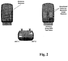
- Figure 2 shows the BelAir100D physical view with two RMs each with 1 antenna which is the preferred embodiment, not covered by the claimed invention, of the MS.
- the antennas may not be co-located with the MS.
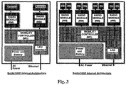
- Figure 3 shows the BelAir100D and BelAir200D logical architectures with MC, RM, antennas, and LIM ports.
- Figures 4A , 4B, and 4C show a plurality of variations on antenna configurations for each device.
- Figure 4A shows the case of eight antennas, each with an azimuth beamwidth (polar plot) of at least 45 degrees, so that the eight antennas form a 360 degree contiguous coverage.
- Figure 4B shows the case of six antennas, each with an azimuth beamwidth (polar plot) of at least 60 degrees, so that the six antennas form a 360 degree contiguous coverage.
- Figure 4C shows the case of four antennas, each with an azimuth beamwidth (polar plot) of at least 90 degrees, so that the four antennas form a 360 degree contiguous coverage.
- These figures show embodiments , not covered by the claimed invention, of the MS and BTS systems; however, anyone knowledgeable in the area can realize variations on this using different numbers of antennas, or multiple units to provide the 360 degrees of coverage.
- the antenna configurations shown in Figures 4A , 4B, and 4C show non-overlapping coverage. As the antennas may be internal or external, it is anticipated that these antenna patterns may need to be fully overlapping. This is especially true for long distant links, where the MS node is locates several miles from the redundant BTS nodes. The angle between the two RF links will be minimal, requiring antennas to be effectively pointing in the same direction.
- Figure 5 shows an optional omnidirectional antenna designed for use on the BelAir100D/BelAir200D. This antenna enables alternate variants of those cases shown in Figures 4A , 4B, and 4C where the omnidirectional antenna is used to ensure contiguous coverage where antenna patterns do not fully achieve 360 degrees of coverage.
- FIG. 6 shows the BelAir200D with external high gain parabolic antennas for shore mounting and long distance links into the harbor.
- These high gain antennas have narrow beam widths of 4-12 degrees requiring multiple antennas, each angled to create a contiguous coverage of the oceans approach to a harbor.
- the high gain antennas as high as 32 dBi, yield a high capacity link to a remote MS many miles away.
- Multiple technologies may be used for these applications including vertical/horizontal polarization diversity, which is available on all antenna types, or circularly polarized antennas with different left/right spins.
- Figure 7 shows a pier-side network configuration of BTS and MS nodes.
- This network configuration shows the links: BTS to BTS; BTS to MS; and MS to MS.
- This network configuration also shows redundant paths where the solid lines are the main path, and the dotted lines are the redundant paths.
- Figure 8A shows a harbor network configuration, with long distance links achieved via high gain antennas such as parabolic antennas.
- full coverage of the harbor is achieved using multiple non-overlapping antenna patterns.
- the four BelAir200D BTS units indicated in Figure 8A as 1, 2, 3, 4 provide 180 degrees of coverage using 16 antennas with beam widths of approximately 11.25 degrees.
- Figure 8B shows the same harbor network configuration as shown in Figure 8A , but with redundant links from BTS units 5, 6, 7, and 8. Similar configurations can be used for outdoor coverage of navy, army or air force bases.
- BTS may be located around the perimeter and within campus, and with MS nodes on road vehicles, or as part of a mobile ground crew.
- Associated with the invention is a method (algorithm) executed by the mobility controller (MC) for auto-selection of antennas and radio modules (RMs).
- the algorithm comprises three orthogonal and concurrent algorithms, although the first algorithm is optional and may be performed manually by network installers.
- the purpose of the first algorithm is to establish network connectivity of BTS nodes. These nodes are maintained by a network management system, but must either be programmed or must otherwise learn an optimized network deployment using the following steps:
- the purpose of the second algorithm is to establish and maintain a first optimal (primary) and second optimal (secondary) link from each MS to a BTS to establish network connectivity.
- This second algorithm is maintained by the mobility controller in the mobility station and relies on the BTS sending out beacons, each consisting of MAC (medium Access Control) address, a system identifier (SSID), and an availability indication as described above.
- MAC medium Access Control
- SSID system identifier
- the purpose of the third algorithm is to establish and maintain a first optimal (primary) and second optimal (secondary) link from each of the MS-to-MS nodes to establish network connectivity.
- This third algorithm is maintained by the MC in the MS and relies on the availability of unconnected radios-effectively, links which are still "available". These links are the most tenuous, as they are in full mobility, and have a special "availability" status which is to indicate that they are MS-to-MS links.
- This third algorithm relies on MS nodes sending out beacons, on each unconnected RM, each comprising MAC (Medium Access Control) address, a system identifier (SSID), and an availability indication, indicating whether the link is free or is in use, and whether it is a primary or secondary link.
- MAC Medium Access Control
- SSID system identifier
- the disclosure and teachings provided herein should be interpreted in view of the following.
- SNR signal- to-noise ratio
- BER bit error rate
- link throughput link capacity
- the algorithms in all cases may be tuned by the NMS system, such as the introduction of exclusion lists, or permanent links.
- P2P links these are merely one preferred example.
- Point-to- multipoint (P2MP) links may be employed with the provision that the transmitted beacons include multiple instances of link information, such as separate MAC addresses for each P2MP link end point.
- beacons have been described as a means to disseminate the link information. However, beacons are disclosed only as one example of how this information may be transferred. In an alternative embodiment, not covered by the claimed invention, the beacons may be suppressed, and the BTS or MS station may be required to issue "probe requests" to determine if a BTS or MS exists, and if so, to receive the details on the link status.
- the algorithms are referred to as a "first”, “second”, and “third” algorithm, in a preferred embodiment, not covered by the claimed invention, of the invention, these algorithms constitute a single algorithms that is embedded within each MS and BTS.
- the nodes are pre-provisioned to be “BTS” or "MS” nodes and therefore operate only specific aspects of the first, second, and third algorithms.
- nodes are provisioned by the NMS once connectivity is established.
Description
- This application claims priority benefit of
U.S. Provisional Patent Application No. 61/077,697, filed July 2, 2008 - This invention describes a high performance wireless mesh architecture which has been optimized for mobile end points. It is intended for Navy applications, where the wireless mesh network extends between mobile ships and includes ship-to- shore links, but it is equally applicable to other mobile elements on, in, or under land, air, sea, or space.
- Naval ships have relied on hardwired connections for network LAN connectivity while in harbor. Under non-combative conditions, these ships disable high powered military band communications when in close proximity to port, to minimize interference with civilian communications systems. This invention provides a high performance wireless mesh network, which connects the naval ships to the naval port communications LAN. This patent describes the nodes used in the network, network design with mobility specific features, and the controller and algorithms used including the method of automatic connectivity of multiple point-to-point (P2P) mobile ship radios to fixed shore side radios. Multi-radio P2P mesh switch-routers perform automatic discovery and connectivity of point to point links as RF link line of sight is created. This invention is the first realization of such a network for naval applications. Prior to this invention, no wideband wireless near shore communication systems were employed.
- This invention is equally applicable to other mobile elements such as soldiers, animals, or vehicles which traverse over, through, or under the land, sea, air, or space.
- Document
US 2004/001442 A1 may be construed to disclose a wireless network using nodes that perform both distribution and backhaul functions. These nodes constitute the key elements of a wireless network that would be deployed and controlled by a wireless network operator. Each node contains a distribution wireless module which is wirelessly coupled to the wireless end user device using a point to multipoint scheme. Also integrated into each node is at least one backhaul wireless module with a directional wireless antenna. Each backhaul wireless module communicates by way of a point to point wireless link with the backhaul module of one other node. The nodes in the wireless network are interconnected to form a mesh backhaul network. Because of the nature of a mesh network, data traffic can be routed around obstacles that may prevent line of site links. Furthermore, the mesh network allows dynamic routing of data traffic to avoid congestion points or downed links in the network. - Document
GB 2,433,859 A - According to the disclosure, there is provided a network according to the independent claim. Developments are set forth in the dependent claim.
-
-
Figure 1 shows an illustration of a radio transceiver with a directional antenna array that is intended for use as a base transceiver station node according to a preferred embodiment not covered by the claimed invention. -
Figure 2 shows an illustration of a radio transceiver with a directional antenna array that is intended for use as a mobile station node according to a preferred embodiment not covered by the claimed invention. -
Figure 3 shows internal architectures for the radio transceivers ofFigures 1 and2 , respectively. -
Figures 4A ,4B, and 4C show alternative antenna configurations for the radio transceivers ofFigures 1 and2 . -
Figure 5 shows an alternative omnidirectional antenna for use with the radio transceivers ofFigures 1 and2 . -
Figure 6 shows an external high gain parabolic antenna for use with the radio transceiver ofFigure 1 . -
Figure 7 shows an exemplary configuration of base station transceiver nodes and mobile transceiver nodes according to a preferred embodiment not covered by the claimed invention. -
Figures 8A and8B show exemplary coverage areas for alternative antenna configurations using the radio transceivers ofFigures 1 and2 . - The present invention details a wireless mobility network consisting of fixed and mobile nodes. Unlike traditional cellular or packet data networks, where the fixed network consists of multi-radio base transceiver stations (BTSs), and single radio cell phones or mobile stations (MSs), this invention employs multiple radios in both the BTSs and MSs.
- Furthermore, and unlike traditionally wireless networks where the BTS typically employ directional antennas most often in a sectorized arrangement, and the MSs utilize omni-directional antennas, the present invention employs directional antennas at both the BTS and MS end points. In addition, unique to the present invention is that the MSs, as described above containing multiple radios, also contain at a minimum, two high gain directional antennas.
- All nodes-fixed (BTSs) and mobile (MSs), include a mobility controller (MC) that controls two or more radio modules (RMs), and where each radio module selects two or more directional or omni-directional antennas.
- Multiple variations of RMs are employed depending on spectrum availability and throughput requirements. For operation in the 24000-2483.5 MHz ISM band, an Access RM (ARM) is employed. Two versions of RMs called the Backhaul Radio Module (BRM3, BRM4), and the Enhanced Radio Modules (ERM1, ERM2) are employed for 5250-5850 MHz unlicensed band operation. A Military band RM (MRM) is employed for 4400-4940 MHz operation. A Public Safety band RM (PSM) is employed for licensed 4940-4990 MHz operation. A Japanese RM (JRM) is employed for 4900-5100 MHz operation. A Transport RM (TRM) is employed for operation in the Intelligent Transport System (ITS) band from 5850-5925 MHz. An IEEE 802.16d WiMAX RM (WRM) is employed for operation in the licensed bands of 2300-2360 MHz (WRM1), 2500-2700 MHz (WRM2, WRM3), 3500-3900 MHz (WRM4), and unlicensed band of 5250-5850 MHz (WRM5). As new technologies become available enabling new services, enhanced performance, or customer specific requirements, the RMs used to form the P2P links may change. For example, higher frequency "common carrier" RMs (CRMx) may be employed to utilize common carrier spectrum at 6 GHz, 11 GHz, 13 GHz, 19 GHz, 23 GHz and 28 GHz for example. Although this spectrum is carefully controlled and licensed by the FCC for fixed wireless links, its application in naval harbors, air force bases, and army bases is controlled by NTIA, and may be used for this application, with assurances of control over radio frequency spill into civilian territories. Additionally, multiple and different RMs may be employed in the same BTS or MS.
- With two or more RMs, the MC can maintain fully redundant links on the same or independent frequencies, to ensure high resiliency to interference from known or unknown sources. With two or more radios, the mobility controller is able to mesh with other mobile or fixed nodes, providing multiple independent links to further guarantee network performance. The high performance point-to-point (P2P) radios provide narrow beamwidth radio frequency links enabling high interference rejection characteristics for both unlicensed and licensed frequencies. Such high gain P2P links ensure optimal radio link performance, for high throughput and low latency to transport voice and data IP and pseudo-wire streams.
- In accordance with one or more embodiments not covered by the present invention, each BTS node contains four IEEE 802.1 In MRM radios, where each MRM is able to selects one of two directional antennas. The embodiment, not covered by the claimed invention, requires two MS configurations: one for smaller fleet ships contains two MRM radios each connected to a single directional antenna; and one for larger fleet ships, such as air craft carriers, contains up to four MRMs. In the BTS, the MC dynamically selects the optimum MRM according to the algorithms described in this application, and associated antennas to maintain independent wireless links to other BTS or MS nodes. In the MS, the MC dynamically selects the optimum MRM for a primary link, and the alternate MRM for a secondary link. Although the MRM utilizes the IEEE 802.1 In standard, and operates in the 4400-4940 MHz military spectrum, anyone of multiple standard or proprietary wireless interface technologies, and anyone of multiple licensed or unlicensed bands may have been employed.
- The invention includes a fully redundant network path to a fixed node where any one of multiple network physical layer connections may be used to connect to the wired LAN. These interfaces may exist on any of the fixed or mobile nodes and include, but are not limited to 10/100/1000BASE-TX, T1/E1/T3/E3 or other TDM interfaces carrying TDM traffic or packet data tunneled over TDM interfaces; optical interfaces such as 100/1000BASE-FX or PON (Passive Optical Network); DSL (Digital Subscriber Line) interfaces; broadband interface such as DOCSIS, serial interfaces such as RS232, Firewire, USB1 or USB2.0 or its derivatives, parallel interfaces such as SCSI, or other, multiple analogue interfaces, and any form of proprietary interface including a wireless interface, standard or proprietary to the wired LAN.
- Referring to
Figure 1 , in accordance with one or more embodiments not covered by the present invention,Figure 1 shows the BelAir200D physical view with four RMs each with 2 antennas. This figure relates to the embodiment, not covered by the claimed invention, of the BTS which has eight RMs and two antennas per RM. The antennas need not be co-located with the BTS. - Referring to
Figures 2 and3 ,Figure 2 shows the BelAir100D physical view with two RMs each with 1 antenna which is the preferred embodiment, not covered by the claimed invention, of the MS. The antennas may not be co-located with the MS.Figure 3 shows the BelAir100D and BelAir200D logical architectures with MC, RM, antennas, and LIM ports. - Referring to
Figures 4A ,4B, and 4C , these figures show a plurality of variations on antenna configurations for each device.Figure 4A shows the case of eight antennas, each with an azimuth beamwidth (polar plot) of at least 45 degrees, so that the eight antennas form a 360 degree contiguous coverage.Figure 4B shows the case of six antennas, each with an azimuth beamwidth (polar plot) of at least 60 degrees, so that the six antennas form a 360 degree contiguous coverage.Figure 4C shows the case of four antennas, each with an azimuth beamwidth (polar plot) of at least 90 degrees, so that the four antennas form a 360 degree contiguous coverage. These figures show embodiments , not covered by the claimed invention, of the MS and BTS systems; however, anyone knowledgeable in the area can realize variations on this using different numbers of antennas, or multiple units to provide the 360 degrees of coverage. - The antenna configurations shown in
Figures 4A ,4B, and 4C show non-overlapping coverage. As the antennas may be internal or external, it is anticipated that these antenna patterns may need to be fully overlapping. This is especially true for long distant links, where the MS node is locates several miles from the redundant BTS nodes. The angle between the two RF links will be minimal, requiring antennas to be effectively pointing in the same direction. - Referring to
Figure 5, Figure 5 shows an optional omnidirectional antenna designed for use on the BelAir100D/BelAir200D. This antenna enables alternate variants of those cases shown inFigures 4A ,4B, and 4C where the omnidirectional antenna is used to ensure contiguous coverage where antenna patterns do not fully achieve 360 degrees of coverage. - Referring to
Figure 6, Figure 6 shows the BelAir200D with external high gain parabolic antennas for shore mounting and long distance links into the harbor. These high gain antennas have narrow beam widths of 4-12 degrees requiring multiple antennas, each angled to create a contiguous coverage of the oceans approach to a harbor. The high gain antennas, as high as 32 dBi, yield a high capacity link to a remote MS many miles away. Multiple technologies may be used for these applications including vertical/horizontal polarization diversity, which is available on all antenna types, or circularly polarized antennas with different left/right spins. - Referring to
Figure 7 , in accordance with one or more embodiments not covered by the present invention,Figure 7 shows a pier-side network configuration of BTS and MS nodes. This network configuration shows the links: BTS to BTS; BTS to MS; and MS to MS. This network configuration also shows redundant paths where the solid lines are the main path, and the dotted lines are the redundant paths. - Referring to
Figures 8A and8B ,Figure 8A shows a harbor network configuration, with long distance links achieved via high gain antennas such as parabolic antennas. In this network configuration, full coverage of the harbor is achieved using multiple non-overlapping antenna patterns. For example, the four BelAir200D BTS units indicated inFigure 8A as 1, 2, 3, 4 provide 180 degrees of coverage using 16 antennas with beam widths of approximately 11.25 degrees.Figure 8B shows the same harbor network configuration as shown inFigure 8A , but with redundant links fromBTS units - Associated with the invention is a method (algorithm) executed by the mobility controller (MC) for auto-selection of antennas and radio modules (RMs). The algorithm comprises three orthogonal and concurrent algorithms, although the first algorithm is optional and may be performed manually by network installers.
- The purpose of the first algorithm is to establish network connectivity of BTS nodes. These nodes are maintained by a network management system, but must either be programmed or must otherwise learn an optimized network deployment using the following steps:
- 1. BTS nodes which are wired connected to the network management system (NMS) using one of the listed wired connectivity solutions are enabled to transmit beacons on each radio module (RM) containing system identification information (SSID), a medium access control (MAC) address specific to that RM, and an availability indication indicating whether the link is free or is in use, and whether it is a primary or secondary link. The selected channel is allocated from the NMS system, but could have been determined locally through a free channel selection process.
- 2. Other BTS nodes that are not wire connected scan all combinations of RMs, channels, and antennas, to obtain a list of available nodes, sorted by BTS signal strength with associated RM and antenna to select and establish a first optimal link to the wired BTS, setting the link status to "unavailable". Once these BTS systems have an established connectivity to the NMS, they are enabled to transmit beacons on each RM as described above.
- 3. Each BTS is enabled by the NMS to establish a predetermined number of links to other BTS nodes, with the remaining links reserved for MS nodes.
- The purpose of the second algorithm is to establish and maintain a first optimal (primary) and second optimal (secondary) link from each MS to a BTS to establish network connectivity. This second algorithm is maintained by the mobility controller in the mobility station and relies on the BTS sending out beacons, each consisting of MAC (medium Access Control) address, a system identifier (SSID), and an availability indication as described above.
- 1. The MC in each MS node controls each RM to scan all available channels searching for BTS nodes, using each attached antenna, to obtain a list of available nodes, sorted by signal strength with associated RM and antenna.
- 2. The MC in each MS selects a first optimal combination of RM, channel, and antenna and establishes a link to the BTS node based on the signal strength. The MC then enables this primary link to carry data traffic. Primary links may steal secondary links, resulting in an iterative link optimization process.
- 3. The MC in each MS selects a second optimal combination of RM, channel, and antenna and establishes a link based on the signal strength. This is the secondary link and is enabled, as a hot stand-by, but does not carry data traffic.
- 4. The MC in each BTS compares the primary link to the secondary link, and if the primary link degrades below the secondary link, then the secondary link becomes the primary link, and the primary link becomes the secondary link.
- The purpose of the third algorithm is to establish and maintain a first optimal (primary) and second optimal (secondary) link from each of the MS-to-MS nodes to establish network connectivity. This third algorithm is maintained by the MC in the MS and relies on the availability of unconnected radios-effectively, links which are still "available". These links are the most tenuous, as they are in full mobility, and have a special "availability" status which is to indicate that they are MS-to-MS links.
- This third algorithm relies on MS nodes sending out beacons, on each unconnected RM, each comprising MAC (Medium Access Control) address, a system identifier (SSID), and an availability indication, indicating whether the link is free or is in use, and whether it is a primary or secondary link.
- 1. The MC in each MS node controls each unconnected RM to scan all available channels searching for other MS nodes, using each attached antenna, to obtain a list of available nodes, sorted by signal strength with associated RM and antenna.
- 2. The MC in each MS selects a first optimal combination of RM, channel, and antenna and establishes a link to the MS node based on the signal strength. The MC then enables this primary link to carry data traffic.
- 3. The MC in each MS selects a second optimal combination of RM, channel, and antenna and establishes a link based on the signal strength. This is the secondary link and is enabled, as a hot stand-by, but does not carry data traffic.
- 4. The MC in each MS compares the primary link to the secondary link, and if the primary link degrades below the secondary link, or if the secondary link is a MS- to-BTS link, then the secondary link becomes the primary link, and the primary link becomes the secondary link.
- Moreover, the disclosure and teachings provided herein should be interpreted in view of the following. First, although the algorithms use signal strength as a metric for maintaining a link, other link quality parameters may be used, such as signal- to-noise ratio (SNR), bit error rate (BER), link throughput, link capacity, or any other such meaningful metric. Second, the algorithms in all cases may be tuned by the NMS system, such as the introduction of exclusion lists, or permanent links. Third, although the algorithms show P2P links, these are merely one preferred example. Point-to- multipoint (P2MP) links may be employed with the provision that the transmitted beacons include multiple instances of link information, such as separate MAC addresses for each P2MP link end point. Fourth, beacons have been described as a means to disseminate the link information. However, beacons are disclosed only as one example of how this information may be transferred. In an alternative embodiment, not covered by the claimed invention, the beacons may be suppressed, and the BTS or MS station may be required to issue "probe requests" to determine if a BTS or MS exists, and if so, to receive the details on the link status.
- Although the algorithms are referred to as a "first", "second", and "third" algorithm, in a preferred embodiment, not covered by the claimed invention, of the invention, these algorithms constitute a single algorithms that is embedded within each MS and BTS. In one embodiment, not covered by the claimed invention, the nodes are pre-provisioned to be "BTS" or "MS" nodes and therefore operate only specific aspects of the first, second, and third algorithms. In an alternative embodiment, not covered by the claimed invention, nodes are provisioned by the NMS once connectivity is established.
Claims (2)
- A network for maintaining communication, comprising:a plurality of nodes, each node being one of a base transceiver station (fig. 8B: 1-8) and a mobile station and being configured to communicate with other nodes of the plurality of nodes;a plurality of radio modules associated with each node, each radio module being configured to establish a link with a radio module associated with another one of the plurality of nodes;a mobility controller associated with each node, each mobility controller being configured to control the radio modules associated with that node; anda plurality of directional antennas (fig. 4A: 1-8) associated with each node, each directional antenna being configured to maintain one of the links concurrent to another of the antennas to maintain another link,wherein the links are between any combination of base transceiver stations and mobile stations.
- The network of claim 1, wherein at least a first node of the plurality of nodes comprises a base transceiver station and at least a second node of the plurality of nodes comprises a mobile station, andwherein the at least first node comprises at least a first radio module and a second radio module of the plurality of radio modules, and a first directional antenna and a second directional antenna of the plurality of directional antennas, andwherein the at least second node comprises at least a third radio module and a fourth radio module of the plurality of radio modules, and a third directional antenna and a fourth directional antenna of the plurality of directional antennas, andwherein the at least first and third directional antennas are configured to maintain an active link, and wherein the at least second and fourth directional antennas are configured to maintain a standby link.
Applications Claiming Priority (2)
| Application Number | Priority Date | Filing Date | Title |
|---|---|---|---|
| US7769708P | 2008-07-02 | 2008-07-02 | |
| PCT/IB2009/008011 WO2010043983A2 (en) | 2008-07-02 | 2009-07-01 | High performance mobility network with autoconfiguration |
Publications (3)
| Publication Number | Publication Date |
|---|---|
| EP2294874A2 EP2294874A2 (en) | 2011-03-16 |
| EP2294874A4 EP2294874A4 (en) | 2016-02-10 |
| EP2294874B1 true EP2294874B1 (en) | 2021-01-27 |
Family
ID=42106978
Family Applications (1)
| Application Number | Title | Priority Date | Filing Date |
|---|---|---|---|
| EP09820331.8A Active EP2294874B1 (en) | 2008-07-02 | 2009-07-01 | Wireless mesh network |
Country Status (6)
| Country | Link |
|---|---|
| US (3) | US8290440B2 (en) |
| EP (1) | EP2294874B1 (en) |
| CN (2) | CN103379509A (en) |
| CA (1) | CA2725520C (en) |
| HK (1) | HK1158443A1 (en) |
| WO (1) | WO2010043983A2 (en) |
Families Citing this family (6)
| Publication number | Priority date | Publication date | Assignee | Title |
|---|---|---|---|---|
| US9319125B2 (en) * | 2012-07-19 | 2016-04-19 | Electronics And Telecommunications Research Institute | Method and apparatus of wireless communication by using multiple directional antennas |
| CN102917369B (en) * | 2012-10-18 | 2016-05-04 | 中国船舶重工集团公司第七一〇研究所 | A kind of marine system of broadband wireless communication |
| WO2015038894A2 (en) * | 2013-09-12 | 2015-03-19 | Olea Networks, Inc. | Portable wireless mesh device |
| KR101543147B1 (en) * | 2014-02-11 | 2015-08-07 | 현대자동차주식회사 | Method initializing radio network for radio module in vehicle |
| WO2019003794A1 (en) * | 2017-06-26 | 2019-01-03 | 日本電気株式会社 | Antenna direction adjustment device, antenna direction adjustment system, and method thereof |
| WO2020162817A1 (en) * | 2019-02-06 | 2020-08-13 | Aecorlink Ab | An antenna terminal, a rotatable antenna platform and methods for maritime use |
Family Cites Families (40)
| Publication number | Priority date | Publication date | Assignee | Title |
|---|---|---|---|---|
| US5475866A (en) * | 1991-08-27 | 1995-12-12 | Motorola Inc. | System for informing secondary users of which radio channels are usable in which geographic region |
| JPH09186644A (en) * | 1995-12-29 | 1997-07-15 | Kawasaki Heavy Ind Ltd | Direction control method of directional antenna and direction controller |
| US5818389A (en) * | 1996-12-13 | 1998-10-06 | The Aerospace Corporation | Method for detecting and locating sources of communication signal interference employing both a directional and an omni antenna |
| US6167286A (en) * | 1997-06-05 | 2000-12-26 | Nortel Networks Corporation | Multi-beam antenna system for cellular radio base stations |
| US6075997A (en) * | 1997-11-03 | 2000-06-13 | Telefonaktiebolaget L M Ericsson (Publ) | Automatic configuration of antenna near parts equipment |
| US6229486B1 (en) * | 1998-09-10 | 2001-05-08 | David James Krile | Subscriber based smart antenna |
| US7162273B1 (en) * | 2000-11-10 | 2007-01-09 | Airgain, Inc. | Dynamically optimized smart antenna system |
| US20030043773A1 (en) * | 2001-08-31 | 2003-03-06 | Hyokang Chang | Multilink wireless access scheme for multiband operation in wireless mobile networks |
| US7372828B2 (en) * | 2001-12-21 | 2008-05-13 | Broadcom Corporation | Wireless access point management in a campus environment |
| KR100465208B1 (en) * | 2002-04-02 | 2005-01-13 | 조광선 | System, Apparatus, and Method for Wireless Mobile Communication in association with Mobile AD-HOC Network Support |
| US7164667B2 (en) * | 2002-06-28 | 2007-01-16 | Belair Networks Inc. | Integrated wireless distribution and mesh backhaul networks |
| US7363039B2 (en) * | 2002-08-08 | 2008-04-22 | Qualcomm Incorporated | Method of creating and utilizing diversity in multiple carrier communication system |
| CA2500636A1 (en) * | 2002-09-30 | 2004-04-08 | Ipr Licensing, Inc. | Method and apparatus for antenna steering for wlan |
| US7212499B2 (en) * | 2002-09-30 | 2007-05-01 | Ipr Licensing, Inc. | Method and apparatus for antenna steering for WLAN |
| US7171223B2 (en) * | 2003-01-10 | 2007-01-30 | Belair Networks, Inc. | Automatic antenna selection for mesh backhaul network nodes |
| US7953372B2 (en) * | 2003-04-07 | 2011-05-31 | Yoram Ofek | Directional antenna sectoring system and methodology |
| US7587173B2 (en) * | 2003-06-19 | 2009-09-08 | Interdigital Technology Corporation | Antenna steering for an access point based upon spatial diversity |
| US7302278B2 (en) * | 2003-07-03 | 2007-11-27 | Rotani, Inc. | Method and apparatus for high throughput multiple radio sectorized wireless cell |
| US7878145B2 (en) * | 2004-06-02 | 2011-02-01 | Varian Semiconductor Equipment Associates, Inc. | Monitoring plasma ion implantation systems for fault detection and process control |
| US7366464B2 (en) * | 2004-06-04 | 2008-04-29 | Interdigital Technology Corporation | Access point operating with a smart antenna in a WLAN and associated methods |
| US20060038738A1 (en) * | 2004-08-18 | 2006-02-23 | Video54 Technologies, Inc. | Wireless system having multiple antennas and multiple radios |
| US7652632B2 (en) * | 2004-08-18 | 2010-01-26 | Ruckus Wireless, Inc. | Multiband omnidirectional planar antenna apparatus with selectable elements |
| US7376398B2 (en) * | 2004-09-10 | 2008-05-20 | Interdigital Technology Corporation | Implementing a smart antenna in wireless local area network |
| US20060098598A1 (en) * | 2004-11-10 | 2006-05-11 | Michael Gallagher | Seamless transitions of active calls between enterprise telecommunications networks and licensed public telecommunications networks |
| US7483696B1 (en) * | 2004-11-29 | 2009-01-27 | Rockwell Collins, Inc. | Cellular wireless network for passengers cabins |
| US7359362B2 (en) * | 2005-01-28 | 2008-04-15 | Microsoft Corporation | Control of a multi-sectored antenna system to improve channel efficiency |
| GB2433859B (en) * | 2005-12-29 | 2008-04-16 | Motorola Inc | Mobile station, system and method for use in wireless communications |
| US8014415B2 (en) * | 2005-12-30 | 2011-09-06 | Meshnetworks, Inc. | Apparatus, system and method for communicating information in a wireless communication network |
| US20070183439A1 (en) * | 2006-01-05 | 2007-08-09 | Osann Robert Jr | Combined directional and mobile interleaved wireless mesh network |
| EP2475106A1 (en) * | 2006-02-28 | 2012-07-11 | Rotani Inc. | Methods and apparatus for overlapping mimo antenna physical sectors |
| US7778226B2 (en) * | 2006-03-30 | 2010-08-17 | Intel Corporation | Device, system and method of coordination among multiple transceivers |
| US7920885B2 (en) * | 2006-05-18 | 2011-04-05 | Samsung Electronics Co., Ltd. | Method and system for establishing a connection on a secondary frequency channel for wireless communication |
| US7620370B2 (en) * | 2006-07-13 | 2009-11-17 | Designart Networks Ltd | Mobile broadband wireless access point network with wireless backhaul |
| US7920883B2 (en) * | 2006-12-28 | 2011-04-05 | Hewlett-Packard Development Company, L.P. | Coordination of transmissions in wireless communications devices |
| JP5138974B2 (en) * | 2007-04-27 | 2013-02-06 | 株式会社日立製作所 | MIMO wireless communication system, MIMO wireless communication apparatus, and wireless communication method |
| US8027293B2 (en) * | 2007-07-16 | 2011-09-27 | Cellport Systems, Inc. | Communication channel selection and use |
| US8594050B2 (en) * | 2007-12-28 | 2013-11-26 | Intel Corporation | Techniques to control wireless personal area networks |
| US8126408B2 (en) * | 2008-01-22 | 2012-02-28 | Provigent Ltd | Multi-mode wireless communication link |
| US20100091818A1 (en) * | 2008-10-14 | 2010-04-15 | Sen Indranil S | Dynamic channel evaluation in wireless communication device |
| US8385978B2 (en) * | 2009-05-22 | 2013-02-26 | Fimax Technology Limited | Multi-function wireless apparatus |
-
2009
- 2009-07-01 US US12/496,398 patent/US8290440B2/en active Active
- 2009-07-01 WO PCT/IB2009/008011 patent/WO2010043983A2/en active Application Filing
- 2009-07-01 CA CA2725520A patent/CA2725520C/en not_active Expired - Fee Related
- 2009-07-01 EP EP09820331.8A patent/EP2294874B1/en active Active
- 2009-07-01 CN CN2013102397389A patent/CN103379509A/en active Pending
- 2009-07-01 CN CN200980125769.3A patent/CN102084694B/en active Active
-
2011
- 2011-11-25 HK HK11112845.9A patent/HK1158443A1/en not_active IP Right Cessation
-
2012
- 2012-10-12 US US13/650,365 patent/US9253755B2/en active Active
-
2015
- 2015-09-11 US US14/851,574 patent/US20150382206A1/en not_active Abandoned
Non-Patent Citations (1)
| Title |
|---|
| None * |
Also Published As
| Publication number | Publication date |
|---|---|
| CA2725520A1 (en) | 2010-04-22 |
| CN103379509A (en) | 2013-10-30 |
| US20120236786A1 (en) | 2012-09-20 |
| WO2010043983A3 (en) | 2010-07-01 |
| US20150382206A1 (en) | 2015-12-31 |
| HK1158443A1 (en) | 2012-07-13 |
| US20130107820A1 (en) | 2013-05-02 |
| WO2010043983A2 (en) | 2010-04-22 |
| US8290440B2 (en) | 2012-10-16 |
| CA2725520C (en) | 2017-03-28 |
| EP2294874A4 (en) | 2016-02-10 |
| CN102084694B (en) | 2014-01-22 |
| US9253755B2 (en) | 2016-02-02 |
| EP2294874A2 (en) | 2011-03-16 |
| CN102084694A (en) | 2011-06-01 |
Similar Documents
| Publication | Publication Date | Title |
|---|---|---|
| US20150382206A1 (en) | High performance mobility network with autoconfiguration | |
| US10084576B2 (en) | Method and system for centralized or distributed resource management in a distributed transceiver network | |
| EP3120418B1 (en) | Modal antenna based communication network and methods for optimization thereof | |
| US7359675B2 (en) | Methods and apparatus for high throughput multiple radio wireless cells and networks | |
| US20020175862A1 (en) | Antenna array | |
| WO2005009054A2 (en) | Methods and apparatus for high throughput multiple radio wireless cells and networks | |
| EP0925654A1 (en) | Control channel for nonterrestrial cellular mobile telecommunication station | |
| US20080122706A1 (en) | Polarization reuse and beam-forming techniques for aeronautical broadband systems | |
| CN102217141A (en) | Antenna device and base station device | |
| KR102254601B1 (en) | Apparatus for multi-hop relay maritime communication | |
| BR102019021059A2 (en) | METHOD AND SYSTEM FOR DYNAMICALLY ASSOCIATING SPACE LAYERS TO BEAMS IN FIXED WIRELESS ACCESS NETWORKS | |
| US6542746B1 (en) | Frequency reuse scheme for point to multipoint radio communication | |
| US10218087B2 (en) | Dual band MIMO antenna and wireless access point | |
| KR101683932B1 (en) | Method for calibrating a terminal with a multi-sector antenna and mesh network terminal | |
| KR20190057041A (en) | Method and apparatus of peer link setting, and method and apparatus of channel switching, in wireless mesh network | |
| US8233406B1 (en) | Communication system and method for operating a control database for a wireless communication system | |
| US9924338B1 (en) | Connecting communication networks via a non-collocated relay | |
| Maliatsos et al. | Diversity in direct mobile-to-mobile communication systems: An experimental approach | |
| Heffner et al. | Network discovery with directional antennas |
Legal Events
| Date | Code | Title | Description |
|---|---|---|---|
| PUAI | Public reference made under article 153(3) epc to a published international application that has entered the european phase |
Free format text: ORIGINAL CODE: 0009012 |
|
| 17P | Request for examination filed |
Effective date: 20110117 |
|
| AK | Designated contracting states |
Kind code of ref document: A2 Designated state(s): AT BE BG CH CY CZ DE DK EE ES FI FR GB GR HR HU IE IS IT LI LT LU LV MC MK MT NL NO PL PT RO SE SI SK SM TR |
|
| AX | Request for extension of the european patent |
Extension state: AL BA RS |
|
| RIN1 | Information on inventor provided before grant (corrected) |
Inventor name: SMITH, ROLAND, A. Inventor name: RAYMENT, STEPHEN Inventor name: CHENIER, MARCEL Inventor name: PARK, DAVE Inventor name: JOHNSON, ERIC Inventor name: WILLIAMS, CHRIS |
|
| RIN1 | Information on inventor provided before grant (corrected) |
Inventor name: SMITH, ROLAND, A. Inventor name: RAYMENT, STEPHEN Inventor name: CHENIER, MARCEL Inventor name: PARK, DAVE Inventor name: JOHNSON, ERIC Inventor name: WILLIAMS, CHRIS |
|
| DAX | Request for extension of the european patent (deleted) | ||
| RIN1 | Information on inventor provided before grant (corrected) |
Inventor name: SMITH, ROLAND, A. Inventor name: RAYMENT, STEPHEN Inventor name: CHENIER, MARCEL Inventor name: PARK, DAVE Inventor name: JOHNSON, ERIC Inventor name: WILLIAMS, CHRIS |
|
| RIN1 | Information on inventor provided before grant (corrected) |
Inventor name: SMITH, ROLAND, A. Inventor name: RAYMENT, STEPHEN Inventor name: CHENIER, MARCEL Inventor name: PARK, DAVE Inventor name: JOHNSON, ERIC Inventor name: WILLIAMS, CHRIS |
|
| RIN1 | Information on inventor provided before grant (corrected) |
Inventor name: SMITH, ROLAND, A. Inventor name: RAYMENT, STEPHEN Inventor name: CHENIER, MARCEL Inventor name: PARK, DAVE Inventor name: JOHNSON, ERIC Inventor name: WILLIAMS, CHRIS |
|
| RAP1 | Party data changed (applicant data changed or rights of an application transferred) |
Owner name: BELAIR NETWORKS INC. |
|
| RIC1 | Information provided on ipc code assigned before grant |
Ipc: H04W 84/18 20090101ALI20150915BHEP Ipc: H04W 16/28 20090101ALI20150915BHEP Ipc: H04W 88/02 20090101ALI20150915BHEP Ipc: H04W 36/30 20090101ALI20150915BHEP Ipc: H01Q 1/24 20060101ALI20150915BHEP Ipc: H04W 48/20 20090101AFI20150915BHEP Ipc: H01Q 21/20 20060101ALI20150915BHEP Ipc: H04W 76/02 20090101ALI20150915BHEP Ipc: H04W 88/08 20090101ALI20150915BHEP Ipc: H04W 84/22 20090101ALI20150915BHEP Ipc: H04W 72/02 20090101ALI20150915BHEP |
|
| RAP1 | Party data changed (applicant data changed or rights of an application transferred) |
Owner name: ERICSSON WIFI INC. |
|
| A4 | Supplementary search report drawn up and despatched |
Effective date: 20160111 |
|
| RIC1 | Information provided on ipc code assigned before grant |
Ipc: H01Q 1/24 20060101ALI20160104BHEP Ipc: H01Q 21/20 20060101ALI20160104BHEP Ipc: H04W 36/30 20090101ALI20160104BHEP Ipc: H04W 88/08 20090101ALI20160104BHEP Ipc: H04W 84/18 20090101ALI20160104BHEP Ipc: H04W 84/22 20090101ALI20160104BHEP Ipc: H04W 72/02 20090101ALI20160104BHEP Ipc: H04W 76/02 20090101ALI20160104BHEP Ipc: H04W 88/02 20090101ALI20160104BHEP Ipc: H04W 48/20 20090101AFI20160104BHEP Ipc: H04W 16/28 20090101ALI20160104BHEP |
|
| STAA | Information on the status of an ep patent application or granted ep patent |
Free format text: STATUS: EXAMINATION IS IN PROGRESS |
|
| 17Q | First examination report despatched |
Effective date: 20181210 |
|
| GRAP | Despatch of communication of intention to grant a patent |
Free format text: ORIGINAL CODE: EPIDOSNIGR1 |
|
| STAA | Information on the status of an ep patent application or granted ep patent |
Free format text: STATUS: GRANT OF PATENT IS INTENDED |
|
| GRAS | Grant fee paid |
Free format text: ORIGINAL CODE: EPIDOSNIGR3 |
|
| RIC1 | Information provided on ipc code assigned before grant |
Ipc: H01Q 21/20 20060101ALI20201117BHEP Ipc: H04W 48/20 20090101AFI20201117BHEP Ipc: H04W 84/22 20090101ALI20201117BHEP Ipc: H04W 16/28 20090101ALI20201117BHEP Ipc: H04W 36/30 20090101ALI20201117BHEP Ipc: H04W 72/02 20090101ALI20201117BHEP Ipc: H04W 84/18 20090101ALI20201117BHEP Ipc: H01Q 1/24 20060101ALI20201117BHEP |
|
| GRAA | (expected) grant |
Free format text: ORIGINAL CODE: 0009210 |
|
| STAA | Information on the status of an ep patent application or granted ep patent |
Free format text: STATUS: THE PATENT HAS BEEN GRANTED |
|
| INTG | Intention to grant announced |
Effective date: 20201201 |
|
| AK | Designated contracting states |
Kind code of ref document: B1 Designated state(s): AT BE BG CH CY CZ DE DK EE ES FI FR GB GR HR HU IE IS IT LI LT LU LV MC MK MT NL NO PL PT RO SE SI SK SM TR |
|
| REG | Reference to a national code |
Ref country code: GB Ref legal event code: FG4D |
|
| REG | Reference to a national code |
Ref country code: CH Ref legal event code: EP |
|
| REG | Reference to a national code |
Ref country code: AT Ref legal event code: REF Ref document number: 1360180 Country of ref document: AT Kind code of ref document: T Effective date: 20210215 |
|
| REG | Reference to a national code |
Ref country code: IE Ref legal event code: FG4D |
|
| REG | Reference to a national code |
Ref country code: DE Ref legal event code: R096 Ref document number: 602009063313 Country of ref document: DE |
|
| REG | Reference to a national code |
Ref country code: NL Ref legal event code: FP |
|
| REG | Reference to a national code |
Ref country code: LT Ref legal event code: MG9D |
|
| REG | Reference to a national code |
Ref country code: AT Ref legal event code: MK05 Ref document number: 1360180 Country of ref document: AT Kind code of ref document: T Effective date: 20210127 |
|
| PG25 | Lapsed in a contracting state [announced via postgrant information from national office to epo] |
Ref country code: PT Free format text: LAPSE BECAUSE OF FAILURE TO SUBMIT A TRANSLATION OF THE DESCRIPTION OR TO PAY THE FEE WITHIN THE PRESCRIBED TIME-LIMIT Effective date: 20210527 Ref country code: BG Free format text: LAPSE BECAUSE OF FAILURE TO SUBMIT A TRANSLATION OF THE DESCRIPTION OR TO PAY THE FEE WITHIN THE PRESCRIBED TIME-LIMIT Effective date: 20210427 Ref country code: NO Free format text: LAPSE BECAUSE OF FAILURE TO SUBMIT A TRANSLATION OF THE DESCRIPTION OR TO PAY THE FEE WITHIN THE PRESCRIBED TIME-LIMIT Effective date: 20210427 Ref country code: LT Free format text: LAPSE BECAUSE OF FAILURE TO SUBMIT A TRANSLATION OF THE DESCRIPTION OR TO PAY THE FEE WITHIN THE PRESCRIBED TIME-LIMIT Effective date: 20210127 Ref country code: FI Free format text: LAPSE BECAUSE OF FAILURE TO SUBMIT A TRANSLATION OF THE DESCRIPTION OR TO PAY THE FEE WITHIN THE PRESCRIBED TIME-LIMIT Effective date: 20210127 Ref country code: GR Free format text: LAPSE BECAUSE OF FAILURE TO SUBMIT A TRANSLATION OF THE DESCRIPTION OR TO PAY THE FEE WITHIN THE PRESCRIBED TIME-LIMIT Effective date: 20210428 Ref country code: HR Free format text: LAPSE BECAUSE OF FAILURE TO SUBMIT A TRANSLATION OF THE DESCRIPTION OR TO PAY THE FEE WITHIN THE PRESCRIBED TIME-LIMIT Effective date: 20210127 |
|
| PG25 | Lapsed in a contracting state [announced via postgrant information from national office to epo] |
Ref country code: SE Free format text: LAPSE BECAUSE OF FAILURE TO SUBMIT A TRANSLATION OF THE DESCRIPTION OR TO PAY THE FEE WITHIN THE PRESCRIBED TIME-LIMIT Effective date: 20210127 Ref country code: PL Free format text: LAPSE BECAUSE OF FAILURE TO SUBMIT A TRANSLATION OF THE DESCRIPTION OR TO PAY THE FEE WITHIN THE PRESCRIBED TIME-LIMIT Effective date: 20210127 Ref country code: LV Free format text: LAPSE BECAUSE OF FAILURE TO SUBMIT A TRANSLATION OF THE DESCRIPTION OR TO PAY THE FEE WITHIN THE PRESCRIBED TIME-LIMIT Effective date: 20210127 Ref country code: AT Free format text: LAPSE BECAUSE OF FAILURE TO SUBMIT A TRANSLATION OF THE DESCRIPTION OR TO PAY THE FEE WITHIN THE PRESCRIBED TIME-LIMIT Effective date: 20210127 |
|
| PG25 | Lapsed in a contracting state [announced via postgrant information from national office to epo] |
Ref country code: IS Free format text: LAPSE BECAUSE OF FAILURE TO SUBMIT A TRANSLATION OF THE DESCRIPTION OR TO PAY THE FEE WITHIN THE PRESCRIBED TIME-LIMIT Effective date: 20210527 |
|
| REG | Reference to a national code |
Ref country code: DE Ref legal event code: R097 Ref document number: 602009063313 Country of ref document: DE |
|
| PG25 | Lapsed in a contracting state [announced via postgrant information from national office to epo] |
Ref country code: SM Free format text: LAPSE BECAUSE OF FAILURE TO SUBMIT A TRANSLATION OF THE DESCRIPTION OR TO PAY THE FEE WITHIN THE PRESCRIBED TIME-LIMIT Effective date: 20210127 Ref country code: EE Free format text: LAPSE BECAUSE OF FAILURE TO SUBMIT A TRANSLATION OF THE DESCRIPTION OR TO PAY THE FEE WITHIN THE PRESCRIBED TIME-LIMIT Effective date: 20210127 Ref country code: CZ Free format text: LAPSE BECAUSE OF FAILURE TO SUBMIT A TRANSLATION OF THE DESCRIPTION OR TO PAY THE FEE WITHIN THE PRESCRIBED TIME-LIMIT Effective date: 20210127 |
|
| PG25 | Lapsed in a contracting state [announced via postgrant information from national office to epo] |
Ref country code: RO Free format text: LAPSE BECAUSE OF FAILURE TO SUBMIT A TRANSLATION OF THE DESCRIPTION OR TO PAY THE FEE WITHIN THE PRESCRIBED TIME-LIMIT Effective date: 20210127 Ref country code: SK Free format text: LAPSE BECAUSE OF FAILURE TO SUBMIT A TRANSLATION OF THE DESCRIPTION OR TO PAY THE FEE WITHIN THE PRESCRIBED TIME-LIMIT Effective date: 20210127 Ref country code: DK Free format text: LAPSE BECAUSE OF FAILURE TO SUBMIT A TRANSLATION OF THE DESCRIPTION OR TO PAY THE FEE WITHIN THE PRESCRIBED TIME-LIMIT Effective date: 20210127 Ref country code: ES Free format text: LAPSE BECAUSE OF FAILURE TO SUBMIT A TRANSLATION OF THE DESCRIPTION OR TO PAY THE FEE WITHIN THE PRESCRIBED TIME-LIMIT Effective date: 20210127 |
|
| PLBE | No opposition filed within time limit |
Free format text: ORIGINAL CODE: 0009261 |
|
| STAA | Information on the status of an ep patent application or granted ep patent |
Free format text: STATUS: NO OPPOSITION FILED WITHIN TIME LIMIT |
|
| 26N | No opposition filed |
Effective date: 20211028 |
|
| PG25 | Lapsed in a contracting state [announced via postgrant information from national office to epo] |
Ref country code: SI Free format text: LAPSE BECAUSE OF FAILURE TO SUBMIT A TRANSLATION OF THE DESCRIPTION OR TO PAY THE FEE WITHIN THE PRESCRIBED TIME-LIMIT Effective date: 20210127 |
|
| REG | Reference to a national code |
Ref country code: CH Ref legal event code: PL |
|
| PG25 | Lapsed in a contracting state [announced via postgrant information from national office to epo] |
Ref country code: MC Free format text: LAPSE BECAUSE OF FAILURE TO SUBMIT A TRANSLATION OF THE DESCRIPTION OR TO PAY THE FEE WITHIN THE PRESCRIBED TIME-LIMIT Effective date: 20210127 |
|
| REG | Reference to a national code |
Ref country code: BE Ref legal event code: MM Effective date: 20210731 |
|
| PG25 | Lapsed in a contracting state [announced via postgrant information from national office to epo] |
Ref country code: LI Free format text: LAPSE BECAUSE OF NON-PAYMENT OF DUE FEES Effective date: 20210731 Ref country code: IT Free format text: LAPSE BECAUSE OF FAILURE TO SUBMIT A TRANSLATION OF THE DESCRIPTION OR TO PAY THE FEE WITHIN THE PRESCRIBED TIME-LIMIT Effective date: 20210127 Ref country code: CH Free format text: LAPSE BECAUSE OF NON-PAYMENT OF DUE FEES Effective date: 20210731 |
|
| PG25 | Lapsed in a contracting state [announced via postgrant information from national office to epo] |
Ref country code: IS Free format text: LAPSE BECAUSE OF FAILURE TO SUBMIT A TRANSLATION OF THE DESCRIPTION OR TO PAY THE FEE WITHIN THE PRESCRIBED TIME-LIMIT Effective date: 20210527 Ref country code: LU Free format text: LAPSE BECAUSE OF NON-PAYMENT OF DUE FEES Effective date: 20210701 Ref country code: FR Free format text: LAPSE BECAUSE OF NON-PAYMENT OF DUE FEES Effective date: 20210731 |
|
| PG25 | Lapsed in a contracting state [announced via postgrant information from national office to epo] |
Ref country code: IE Free format text: LAPSE BECAUSE OF NON-PAYMENT OF DUE FEES Effective date: 20210701 Ref country code: BE Free format text: LAPSE BECAUSE OF NON-PAYMENT OF DUE FEES Effective date: 20210731 |
|
| PG25 | Lapsed in a contracting state [announced via postgrant information from national office to epo] |
Ref country code: HU Free format text: LAPSE BECAUSE OF FAILURE TO SUBMIT A TRANSLATION OF THE DESCRIPTION OR TO PAY THE FEE WITHIN THE PRESCRIBED TIME-LIMIT; INVALID AB INITIO Effective date: 20090701 Ref country code: CY Free format text: LAPSE BECAUSE OF FAILURE TO SUBMIT A TRANSLATION OF THE DESCRIPTION OR TO PAY THE FEE WITHIN THE PRESCRIBED TIME-LIMIT Effective date: 20210127 |
|
| PGFP | Annual fee paid to national office [announced via postgrant information from national office to epo] |
Ref country code: NL Payment date: 20230726 Year of fee payment: 15 |
|
| PGFP | Annual fee paid to national office [announced via postgrant information from national office to epo] |
Ref country code: GB Payment date: 20230727 Year of fee payment: 15 |
|
| PGFP | Annual fee paid to national office [announced via postgrant information from national office to epo] |
Ref country code: DE Payment date: 20230727 Year of fee payment: 15 |
|
| PG25 | Lapsed in a contracting state [announced via postgrant information from national office to epo] |
Ref country code: MK Free format text: LAPSE BECAUSE OF FAILURE TO SUBMIT A TRANSLATION OF THE DESCRIPTION OR TO PAY THE FEE WITHIN THE PRESCRIBED TIME-LIMIT Effective date: 20210127 |