EP2294754B1 - Automatic transfer of information through physical docking of devices - Google Patents
Automatic transfer of information through physical docking of devices Download PDFInfo
- Publication number
- EP2294754B1 EP2294754B1 EP09800763.6A EP09800763A EP2294754B1 EP 2294754 B1 EP2294754 B1 EP 2294754B1 EP 09800763 A EP09800763 A EP 09800763A EP 2294754 B1 EP2294754 B1 EP 2294754B1
- Authority
- EP
- European Patent Office
- Prior art keywords
- media player
- personal media
- speaker system
- wireless network
- information
- Prior art date
- Legal status (The legal status is an assumption and is not a legal conclusion. Google has not performed a legal analysis and makes no representation as to the accuracy of the status listed.)
- Active
Links
Images

Classifications
-
- G—PHYSICS
- G06—COMPUTING; CALCULATING OR COUNTING
- G06F—ELECTRIC DIGITAL DATA PROCESSING
- G06F13/00—Interconnection of, or transfer of information or other signals between, memories, input/output devices or central processing units
- G06F13/38—Information transfer, e.g. on bus
- G06F13/382—Information transfer, e.g. on bus using universal interface adapter
- G06F13/387—Information transfer, e.g. on bus using universal interface adapter for adaptation of different data processing systems to different peripheral devices, e.g. protocol converters for incompatible systems, open system
-
- G—PHYSICS
- G06—COMPUTING; CALCULATING OR COUNTING
- G06F—ELECTRIC DIGITAL DATA PROCESSING
- G06F1/00—Details not covered by groups G06F3/00 - G06F13/00 and G06F21/00
- G06F1/16—Constructional details or arrangements
- G06F1/1613—Constructional details or arrangements for portable computers
- G06F1/1632—External expansion units, e.g. docking stations
Definitions
- Wireless local area networks use RF (radio frequency) signals to link two or more personal computers (“PCs”) or other devices without using wires.
- PCs personal computers
- RF radio frequency
- Most wireless networks will utilize one or more access points to match the footprint of wireless coverage to a desired area in the home.
- an access point may be combined with a switch or gateway to enable PCs and devices on the wireless home network to connect to an external network such as the Internet.
- Wireless RF signals are typically relatively high powered to accommodate variations in antenna designs in the transceivers that are incorporated into networked devices. While such high power generally supports good network performance, it can allow wireless data packets to be unintendedly intercepted by devices outside the network footprint. To deal with this situation, wireless network users will typically utilize one of a variety of encryption technologies that are commonly available such as WPA (Wi-Fi Protected Access) or WEP (Wired Equivalency Privacy).
- WPA Wi-Fi Protected Access
- WEP Wi-Fi Protected Equivalency Privacy
- the information may include, for example, a network identification ("ID”) and a network "key” (i.e., secret information).
- ID network identification
- key i.e., secret information
- the network key such as a WEP key
- the network key can comprise a long string of alphanumeric characters that must be identically and accurately entered into each device.
- some wireless networkable devices provide a graphical user interface ("GUI") or similar means to support manual entry of the required network information, such user interfaces will typically add cost and complexity to the device.
- GUI graphical user interface
- data entry errors can still easily be made which is often a source of frustration to users who are simply looking to add a device to the wireless network without having to put in a lot of effort.
- US 2005/0135628 A1 discloses a system and method for authenticating components in a wireless home entertainment system.
- a removable medium is used to exchange configuration information.
- the medium is engaged with a drive of the server, and configuration information of the server is downloaded on the medium.
- the medium is removed from the server and is engaged with the drive of a component.
- the configuration information of the server is downloaded from the medium to the component, and the configuration information of the component is copied onto the medium.
- the medium is removed from the component and reengaged with the drive of the server, which downloads the configuration of the component to complete the configuration information exchange out-of-band with a primary communication system.
- a personal media player is arranged to capture information, such as wireless network information (including network ID and key) and other kinds of information such as credentials (e.g., user name and password), and then share the information with a wireless networkable device when the player is physically coupled to the device in a docking process.
- information such as wireless network information (including network ID and key) and other kinds of information such as credentials (e.g., user name and password)
- the information is automatically transferred from the player to the device to enable the device to perform some action without any additional effort by the user. This could include, for example, discovering and be securely admitted to the wireless network, or accessing a remote service using the transferred credentials.
- the wireless networkable device is configured as a speaker that includes an integrated docking cradle that is configured to be removably interfaced with the personal media player.
- the player is docked in the cradle and the user is prompted through the graphical user interface ("GUI") to confirm that the user intends for the speaker to join the network. If so, the network information is automatically transferred so that the speaker can discover and securely join the wireless network without further interaction from the user.
- the user is then free to undock the player and then wirelessly play audio content from the player (or other wireless network device) from anywhere within the footprint of the wireless network over the speaker.
- GUI graphical user interface
- FIG 1 shows an illustrative usage environment in which a user may listen to audio content and watch video content rendered by an illustrative personal media player
- FIG 2 shows a front view of an illustrative portable media player supporting a GUI on a display screen as well as user controls;
- FIG 3 shows an illustrative usage environment for a personal media player in which a wireless network includes a network access point that is used to support wireless communication among a number of devices;
- FIG 4 shows several illustrative components that are used to implement the present automatic network information transfer
- FIGs 5 and 6 show a personal media player being docked with an accessory device to automatically transfer network information to the device
- FIG 7 shows details of functional components used to transfer network information to the accessory device
- FIG 8 shows details of the transfer of an accessory ID (identification) to the personal media player
- FIG 9 shows the user playing audio content on an accessory device from a personal media player over a wireless network
- FIG 10 is a flowchart of an illustrative method for automatically transferring network information between docked devices
- FIG 11 is a simplified block diagram that shows various functional components of an illustrative example of a personal media player.
- FIG 12 is a simplified block diagram that shows various physical components of an illustrative example of a personal media player.
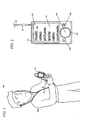
- FIG 1 shows an illustrative portable device usage environment 100 in which a user 105 interacts with digital media content rendered by a personal media player 110.
- the personal media player 110 is configured with capabilities to play audio content such as MP3 files or content from over-the-air radio stations, display video and photographs, and render other content.
- the user 105 will typically use earphones 120 to enable audio content, such as music or the audio portion of video content, to be consumed privately (i.e., without the audio content being heard by others) and at volume levels that are satisfactory for the user while maintaining good battery life in the personal media player.
- Earphones 120 are representative of a class of devices used to render audio which may also be known as headphones, earbuds, headsets, and by other terms.
- Earphones 120 generally will be configured with a pair of audio speakers (one for each ear), or less commonly a single speaker, along with a means to place the speakers close to the user's ears. As shown in FIG 2 , the speakers are wired via cables to a plug 201. The plug 201 interfaces with an audio jack 202 in the personal media player 110.
- FIG 2 also shows a conventional GUI 205 that is rendered on a display screen 218, and user controls 223 that are built in to the personal media player 110.
- the GUI 205 uses menus, icons, and the like to enable the user 105 to find, select, and control playback of media content that is available to the player 110.
- the display screen 218 is also used to render video content, typically by turning the player 110 to a landscape orientation so that the long axis of the display screen 218 is parallel to the ground.
- the user controls 223, in this example, include a gesture pad 225, called a G-Pad, which combines the functionality of a conventional directional pad (i.e., a "D-pad") with a touch sensitive surface as described in U.S. Patent Application US 2009 0125824, filed November 12, 2007 , entitled “User Interface with Physics Engine for Natural Gestural Control,” owned by the assignee of the present application.
- a "back” button 230 and a "play/pause” button 236 are also provided.
- other types of user controls may also be used depending on the requirements of a particular implementation.
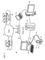
- FIG 3 shows an illustrative usage environment 300 for the personal media player 110 in which a wireless network 306 includes a network access point that is used to support wireless communication among a number of devices 310 1,2 ... N that are each configured for implementing communications over the wireless network.
- Various protocols may be utilized with the wireless network 306 including those complying with Wi-Fi (i.e., the Institute of Electrical and Electronics Engineers, IEEE 802.11 standards family).
- Each device 310 will typically include a wireless transceiver plus the appropriate instructions (such as software code) needed to operate the transceiver.
- the devices include a PC 310 1 , a laptop computer 310 2 , a speaker dock 310 3 , and a game console 310 N .
- the devices 310 are intended to be illustrative and that other devices may be used within the environment 300 as needed to meet the needs of a particular implementation.
- An access point 312 is utilized to provide the devices 310 with access to the wireless network 306.
- the access point 312 is also configured, in this example, with an integrated gateway functionality that enables connectivity to an external network such as the Internet 316.
- Such connectivity allows the devices 310 to access various resources which illustratively include Web resources 321 and a media content delivery service 325.
- FIG 3 also shows the personal media player 110 as typically inserted into a dock 328 for synchronization with the PC 310 1 .
- Dock 328 is coupled to an input port 331 on the PC 310 1 such as USB port (Universal Serial Bus) with a synchronization ("sync") cable 335, in this example.
- a pair of mating connectors (including a dock connector in the player 110 and a device connector in the dock 328) are utilized to implement the connection between the personal media player 110 and the dock 328, where one of the connectors in the pair is disposed in the player and the other is disposed in the recess of the dock 328 in which the player sits.
- the dock 328 also typically provides a charging functionality to charge an onboard battery in the personal media player 110 when it is docked.
- the portable media player 110 may be coupled directly to the sync cable 335 without using the dock 328.
- the personal media player 110 is itself equipped with a Wi-Fi transceiver and may synchronize with the PC 310 1 wirelessly as well as communicate with other devices 310 on the network 306.
- the synchronization process implemented between the player 110 and the PC 310 1 typically enables media content such as music, video, images, games, information, and other data to be downloaded from the media content delivery service 325 or other on-line source over the Internet 316 to the PC 310 1 . From the PC 310 1 , the downloaded media content may be transferred to the player 110. In this way, the PC 310 1 operates as an intermediary or proxy device between the service 325 and the personal media player 110.
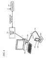
- a network setup utility 410 is instantiated on the PC 310 1 as shown in FIG 4 .
- the network setup utility 410 provides for configuration and setup of the access point 312, as indicated by reference numeral 416.
- the network setup utility 410 may be supported using HTML (Hypertext Markup Language) code that runs on a Web browser, for example.
- the network setup utility 410 may be configured as a standalone application.
- the network setup utility 410 will typically be arranged to specify a network ID and network key that will be utilized by the access point 312.
- various types of settings, preferences, and other configuration information may also be set using the utility 410.
- the network setup utility 410 is further arranged to interact with the personal media player 110 to transfer the network information to the player for storage.
- the player 110 can then automatically transfer the stored network information to other devices that the user 105 intends to add on to the network.
- the utility 410 may be used to configure other types of information that can be transferred from the player 110 to the devices 310.
- information may include credentials such as user name and password used to access an on-line media content service.
- the on-line media content service can be contacted using the credentials to receive a stream of media content such as music or video which can then be rendered by the device.
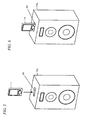
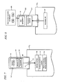
- FIGs 5 and 6 show one illustrative example of such automatic transfer of stored network information from the personal media player 110 to a device 310.
- the device is the speaker 310 3 that includes an integrated docking cradle 503 that is specifically adapted to receive and interact with the player 110 to enable the speaker to later receive a stream of content from the media player that can be rendered.
- the speaker 310 3 is intended as an illustrative example only and that other types of devices may also be adapted to interface with the personal media player 110 in a similar manner.
- the device 310 could also be an image rendering device and the stream of content from the player 110 could include video content, photographs, images, etc.
- the personal media player 110 interfaces with the integrated docking cradle 503 in a way that is similar to the conventional synchronization dock 328 shown in FIG 3 .
- the docking cradle 503 will include a device connector that is arranged to engage with a mating connector in the player 110.
- the network information stored on the player will automatically be transferred to the speaker 310 3 .
- FIG 7 shows details of functional components used to transfer the stored network information 707 from the personal media player 110 to the speaker 310 3 .
- the stored network information 707 will typically be stored in a persistent form in nonvolatile memory of the player 110.
- the docking connector 711 of the player 110 is operatively coupled to the device connector 713 in docking cradle 503, a signal through path is created to enable the stored network information 707, comprising a network ID 717 and network key 721 to be received by a device interface 726 in the speaker 310 3 .
- the personal media player 110 is configured with a GUI component 802 that may be utilized to display a prompt 806 on the display screen of the player 110.
- the prompt 806, in this example, is used to confirm that the user intends to add the speaker 310 3 to the wireless network 306 ( FIG 3 ).
- the device interface 726 is operatively coupled to a wireless transceiver module 730 so that the received network ID 717 and network key 721 may be used by the speaker 310 3 to identify the wireless network 306 ( FIG 3 ) and join on.
- the wireless transceiver module 730 is further operatively coupled to native accessory device functionality 734.
- the functionality 734 is associated with loudspeaker functionality and may typically include digital signal processing, amplification, and the like.
- the wireless transceiver module 730 can receive a digital audio signal over the wireless network 306 that is then converted to an analog signal, amplified, and then rendered by one or more audio transducers in the speaker 310 3 . It is noted at this point that while a single speaker 310 3 is shown, it may be used in a pair-wise arrangement, or include multiple sets of audio transducers in order to reproduce a multi-channel or stereo signal in some implementations.
- the speaker 310 3 is further arranged to transfer an accessory ID 807 that uniquely identifies the speaker to the personal media player 110 through an accessory interface 811.
- This transferred accessory ID 807 is arranged to enable the player 110 to discover the speaker 310 3 on the wireless network 306 after the player is undocked from the speaker as shown in FIG 9 .
- the accessory ID 807 may be arranged as a globally unique identifier ("GUID").
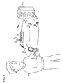
- FIG 9 also shows how the user 105 can use speaker 310 3 to render audio content that is stored on the personal media player 110.
- the player 110 and speaker make a connection to the wireless network 306 through the access point 312.
- Music (or other audio content), video, images, etc., may then be streamed from the player 110 over the wireless network 306 and rendered by the speaker 310 3 or other appropriately configured rendering device.
- such arrangement advantageously enables the user 105 to control playback of content through the speaker 310 3 from a location that falls anywhere within the footprint of the wireless network 306.
- the user may wirelessly connect to other devices on the network in a similar manner.
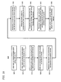
- FIG 10 is a flowchart of an illustrative method 1000 for automatically transferring network information between docked devices.
- the user 105 starts by using the wireless network setup utility 410 to configure the access point 312 with a user selected network ID and key (1005).
- the user 105 then docks the personal media player 110 to the PC 320 1 or synchronizes wirelessly (1010) so that the network information including a network ID and key can be transferred to the player 110 and stored (1015).
- the user 105 can then connect or dock the player 110 to an accessory device such as the speaker 310 3 (1020). After docking, the network information is automatically transferred from the player 110 to the accessory device (1025), and an accessory device ID is transferred from the device to the player 110 (1030).
- an accessory device such as the speaker 310 3
- the user 105 can then undock or disconnect the personal media player 110 from the accessory device (1035).
- the accessory device can discover the wireless network and join it in a secure manner (1040).
- the player 110 can use the accessory device ID to locate and connect to the accessory device on the wireless network 306 through the access point (1045). Once connected, media content from the media player 110 can transmitted to the accessory device for remote rendering.
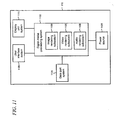
- FIG 11 a simplified block diagram that shows various illustrative functional components of the personal media player 110.
- the functional components include a digital media processing system 1102, a user interface system 1108, a display unit system 1113, a data port system 1124, and a power source system 1128.
- the digital media processing system 1102 further comprises an image rendering subsystem 1130, a video rendering subsystem 1135, and an audio rendering subsystem 1138.
- the digital media processing system 1102 is the central processing system for the personal media player 110 and provides functionality that is similar to that provided by the processing systems found in a variety of electronic devices such as PCs, mobile phones, PDAs, handheld game devices, digital recording and playback systems, and the like.
- Some of the primary functions of the digital media processing system 1102 may include receiving media content files downloaded to the player 110, coordinating storage of such media content files, recalling specific media content files on demand, and rendering the media content files into audio/visual output on the display for the user 105. Additional features of the digital media processing system 1102 may also include searching external resources for media content files, coordinating DRM (digital rights management) protocols for protected media content, and interfacing directly with other recording and playback systems.
- DRM digital rights management
- the digital media processing system 1102 further comprises three subsystems: the video rendering subsystem 1135 which handles all functionality related to video-based media content files, which may include files in MPEG (Moving Picture Experts Group) and other formats; the audio rendering subsystem 1138 which handles all functionality related to audio-based media content including, for example music in the commonly-utilized MP3 format and other formats; and the image rendering subsystem 1130 which handles all functionality related to picture-based media content, including for example JPEG (Joint Photographic Experts Group), GIF (Graphic Interchange Format), and other formats. While each subsystem is shown as being logically separated, each may in fact share hardware and software components with each other and with the rest of the personal media player 110, as may be necessary to meet the requirements of a particular implementation.
- the video rendering subsystem 1135 which handles all functionality related to video-based media content files, which may include files in MPEG (Moving Picture Experts Group) and other formats
- the audio rendering subsystem 1138 which handles all functionality related to audio-based media content including, for
- a display unit system 1113 is also functionally coupled to the digital media processing system 1102 and may comprise the display screen 218 ( FIG 2 ). Audio output through the audio jack 202 ( FIG 2 ) for playback of rendered media content may also be supported by display unit system 1113.
- the display unit system 1113 may also functionally support and complement the operation of the user interface system 1108 by providing visual and/or audio output to the user 105 during operation of the player 110.
- the data port system 1124 is also functionally coupled to the digital media processing system 1102 and provides a mechanism by which the personal media player 110 can interface with external systems in order to download media content.
- the data port system 1124 may comprise, for example, a data synchronization connector port, a network connection (which may be wired or wireless), or other means of connectivity.
- the personal media player 110 has a power source system 1128 that provides power to the entire device:
- the power source system 1128 in this example is coupled directly to the digital media processing system 1102 and indirectly to the other systems and subsystems throughout the player.
- the power source system 1128 may also be directly coupled to any other system or subsystem of the personal media player 110.
- the power source may comprise a battery, a power converter/transformer, or any other conventional type of electricity-providing power source, personal or otherwise.
- FIG 12 is a simplified block diagram that shows various illustrative physical components of the personal media player 110 based on the functional components shown in FIG 11 and described in the accompanying text (which are represented in FIG 12 by dashed lines) including the digital media processing system 1102, the user interface system 1108, the display unit system 1113, the data port system 1124, and the power source system 1128. While each physical component is shown as included in only a single functional component in FIG 12 the physical components may, in fact, be shared by more than one functional component.
- the physical components include a central processor 1202 coupled to a memory controller/chipset 1206 through, for example, a multi-pin connection 1212.
- the memory controller/chipset 1206 may be, in turn, coupled to random access memory (“RAM”) 1215 and/or non-volatile memory 1218 such as solid-state or Flash memory.
- RAM random access memory
- non-volatile memory 1218 such as solid-state or Flash memory.
- These physical components, through connectivity with the memory controller/chipset 1206, may be collectively coupled to a hard disk drive 1221 (or other solid-state memory) via a controller 1225, as well as to the rest of the functional component systems via a system bus 1230.
- a rechargeable battery 1232 may be used to provide power to the components using one or more connections (not shown).
- the battery 1232 may also be coupled to the external AC power adapter 1233 or receive power via the sync cable 335 when it is coupled to the PC 310 1 ( FIG 3 ).
- the display screen 218 is associated with a video graphics controller 1234.
- the video graphics controller will typically use a mix of software, firmware, and/or hardware, as is known in the art, to implement the GUI on the display screen 218.
- these components comprise the display unit system 1113 and may be directly or indirectly connected to the other physical components via the system bus 1230.
- the user controls 223 are associated with a user control interface 1242 in the user interface system 1008 that implements the user control functionality that is used to support the interaction with the GUI as described above.
- a network port 1245 and associated network interface 1248, along with the sync port 1252 and its associated controller 1253 may constitute the physical components of the data port system 1124. These components may also directly or indirectly connect to the other components via the system bus 1230.
Description
- Wireless local area networks ("LANs") use RF (radio frequency) signals to link two or more personal computers ("PCs") or other devices without using wires. Particularly for home users, wireless networking has become very popular due to straightforward infrastructure installation, low cost, and the ease with which new devices may be added to the network. Most wireless networks will utilize one or more access points to match the footprint of wireless coverage to a desired area in the home. Sometimes an access point may be combined with a switch or gateway to enable PCs and devices on the wireless home network to connect to an external network such as the Internet.
- Wireless RF signals are typically relatively high powered to accommodate variations in antenna designs in the transceivers that are incorporated into networked devices. While such high power generally supports good network performance, it can allow wireless data packets to be unintendedly intercepted by devices outside the network footprint. To deal with this situation, wireless network users will typically utilize one of a variety of encryption technologies that are commonly available such as WPA (Wi-Fi Protected Access) or WEP (Wired Equivalency Privacy).
- Utilization of these technologies can make it difficult for the intercepted data to be decrypted and read. However, for such technologies to work each of the wireless devices on the network must have access to commonly-utilized network information. The information may include, for example, a network identification ("ID") and a network "key" (i.e., secret information). A device will use the network information to discover and then be admitted to the network that it is looking to join.
- While wireless networks generally perform satisfactorily, it is often inconvenient for users to populate the commonly-utilized network information across all of the devices that the user wishes to have on a given network. In particular, the network key, such as a WEP key, can comprise a long string of alphanumeric characters that must be identically and accurately entered into each device. While some wireless networkable devices provide a graphical user interface ("GUI") or similar means to support manual entry of the required network information, such user interfaces will typically add cost and complexity to the device. In addition, data entry errors can still easily be made which is often a source of frustration to users who are simply looking to add a device to the wireless network without having to put in a lot of effort. Accordingly, it would be desirable to improve the manner in which network information may be populated in wireless networkable devices.
US 2005/0135628 A1 discloses a system and method for authenticating components in a wireless home entertainment system. A removable medium is used to exchange configuration information. The medium is engaged with a drive of the server, and configuration information of the server is downloaded on the medium. Then, the medium is removed from the server and is engaged with the drive of a component. The configuration information of the server is downloaded from the medium to the component, and the configuration information of the component is copied onto the medium. The medium is removed from the component and reengaged with the drive of the server, which downloads the configuration of the component to complete the configuration information exchange out-of-band with a primary communication system. - The invention is defined according to the independent method and apparatus claims.
- A personal media player is arranged to capture information, such as wireless network information (including network ID and key) and other kinds of information such as credentials (e.g., user name and password), and then share the information with a wireless networkable device when the player is physically coupled to the device in a docking process. When the personal media player is docked, the information is automatically transferred from the player to the device to enable the device to perform some action without any additional effort by the user. This could include, for example, discovering and be securely admitted to the wireless network, or accessing a remote service using the transferred credentials.
- In various illustrative examples, the wireless networkable device is configured as a speaker that includes an integrated docking cradle that is configured to be removably interfaced with the personal media player. The player is docked in the cradle and the user is prompted through the graphical user interface ("GUI") to confirm that the user intends for the speaker to join the network. If so, the network information is automatically transferred so that the speaker can discover and securely join the wireless network without further interaction from the user. The user is then free to undock the player and then wirelessly play audio content from the player (or other wireless network device) from anywhere within the footprint of the wireless network over the speaker.
-
FIG 1 shows an illustrative usage environment in which a user may listen to audio content and watch video content rendered by an illustrative personal media player; -
FIG 2 shows a front view of an illustrative portable media player supporting a GUI on a display screen as well as user controls; -
FIG 3 shows an illustrative usage environment for a personal media player in which a wireless network includes a network access point that is used to support wireless communication among a number of devices; -
FIG 4 shows several illustrative components that are used to implement the present automatic network information transfer; -
FIGs 5 and 6 show a personal media player being docked with an accessory device to automatically transfer network information to the device; -
FIG 7 shows details of functional components used to transfer network information to the accessory device; -
FIG 8 shows details of the transfer of an accessory ID (identification) to the personal media player; -
FIG 9 shows the user playing audio content on an accessory device from a personal media player over a wireless network; -
FIG 10 is a flowchart of an illustrative method for automatically transferring network information between docked devices; -
FIG 11 is a simplified block diagram that shows various functional components of an illustrative example of a personal media player; and -
FIG 12 is a simplified block diagram that shows various physical components of an illustrative example of a personal media player. - Like reference numerals indicate like elements in the drawings. Elements are not drawn to scale unless otherwise indicated.
-
FIG 1 shows an illustrative portabledevice usage environment 100 in which auser 105 interacts with digital media content rendered by apersonal media player 110. In this example, thepersonal media player 110 is configured with capabilities to play audio content such as MP3 files or content from over-the-air radio stations, display video and photographs, and render other content. Theuser 105 will typically useearphones 120 to enable audio content, such as music or the audio portion of video content, to be consumed privately (i.e., without the audio content being heard by others) and at volume levels that are satisfactory for the user while maintaining good battery life in the personal media player. Earphones 120 are representative of a class of devices used to render audio which may also be known as headphones, earbuds, headsets, and by other terms. Earphones 120 generally will be configured with a pair of audio speakers (one for each ear), or less commonly a single speaker, along with a means to place the speakers close to the user's ears. As shown inFIG 2 , the speakers are wired via cables to aplug 201. Theplug 201 interfaces with anaudio jack 202 in thepersonal media player 110. -
FIG 2 also shows a conventional GUI 205 that is rendered on adisplay screen 218, anduser controls 223 that are built in to thepersonal media player 110. The GUI 205 uses menus, icons, and the like to enable theuser 105 to find, select, and control playback of media content that is available to theplayer 110. In addition to supporting the GUI 205, thedisplay screen 218 is also used to render video content, typically by turning theplayer 110 to a landscape orientation so that the long axis of thedisplay screen 218 is parallel to the ground. - The user controls 223, in this example, include a
gesture pad 225, called a G-Pad, which combines the functionality of a conventional directional pad (i.e., a "D-pad") with a touch sensitive surface as described in U.S. Patent ApplicationUS 2009 0125824, filed November 12, 2007 , entitled "User Interface with Physics Engine for Natural Gestural Control," owned by the assignee of the present application. A "back"button 230 and a "play/pause"button 236 are also provided. However, other types of user controls may also be used depending on the requirements of a particular implementation. -
FIG 3 shows anillustrative usage environment 300 for thepersonal media player 110 in which awireless network 306 includes a network access point that is used to support wireless communication among a number of devices 3101,2 ... N that are each configured for implementing communications over the wireless network. Various protocols may be utilized with thewireless network 306 including those complying with Wi-Fi (i.e., the Institute of Electrical and Electronics Engineers, IEEE 802.11 standards family). - Each device 310 will typically include a wireless transceiver plus the appropriate instructions (such as software code) needed to operate the transceiver. In this example, the devices include a PC 3101, a laptop computer 3102, a speaker dock 3103, and a game console 310N. However, it is emphasized that the devices 310 are intended to be illustrative and that other devices may be used within the
environment 300 as needed to meet the needs of a particular implementation. - An
access point 312 is utilized to provide the devices 310 with access to thewireless network 306. Theaccess point 312 is also configured, in this example, with an integrated gateway functionality that enables connectivity to an external network such as theInternet 316. Such connectivity allows the devices 310 to access various resources which illustratively includeWeb resources 321 and a mediacontent delivery service 325. -
FIG 3 also shows thepersonal media player 110 as typically inserted into adock 328 for synchronization with the PC 3101.Dock 328 is coupled to aninput port 331 on the PC 3101 such as USB port (Universal Serial Bus) with a synchronization ("sync")cable 335, in this example. A pair of mating connectors (including a dock connector in theplayer 110 and a device connector in the dock 328) are utilized to implement the connection between thepersonal media player 110 and thedock 328, where one of the connectors in the pair is disposed in the player and the other is disposed in the recess of thedock 328 in which the player sits. Thedock 328 also typically provides a charging functionality to charge an onboard battery in thepersonal media player 110 when it is docked. - In alternative arrangements, the
portable media player 110 may be coupled directly to thesync cable 335 without using thedock 328. Thepersonal media player 110 is itself equipped with a Wi-Fi transceiver and may synchronize with the PC 3101 wirelessly as well as communicate with other devices 310 on thenetwork 306. - The synchronization process implemented between the
player 110 and the PC 3101 typically enables media content such as music, video, images, games, information, and other data to be downloaded from the mediacontent delivery service 325 or other on-line source over theInternet 316 to the PC 3101. From the PC 3101, the downloaded media content may be transferred to theplayer 110. In this way, the PC 3101 operates as an intermediary or proxy device between theservice 325 and thepersonal media player 110. - In this example, a
network setup utility 410 is instantiated on the PC 3101 as shown inFIG 4 . When run, thenetwork setup utility 410 provides for configuration and setup of theaccess point 312, as indicated byreference numeral 416. Thenetwork setup utility 410 may be supported using HTML (Hypertext Markup Language) code that runs on a Web browser, for example. Alternatively, thenetwork setup utility 410 may be configured as a standalone application. Thenetwork setup utility 410 will typically be arranged to specify a network ID and network key that will be utilized by theaccess point 312. In addition, various types of settings, preferences, and other configuration information may also be set using theutility 410. - The
network setup utility 410 is further arranged to interact with thepersonal media player 110 to transfer the network information to the player for storage. Theplayer 110 can then automatically transfer the stored network information to other devices that theuser 105 intends to add on to the network. In alternative implementations, theutility 410 may be used to configure other types of information that can be transferred from theplayer 110 to the devices 310. For example, such information may include credentials such as user name and password used to access an on-line media content service. When later transferred to a device 310, for example, the on-line media content service can be contacted using the credentials to receive a stream of media content such as music or video which can then be rendered by the device. -
FIGs 5 and 6 show one illustrative example of such automatic transfer of stored network information from thepersonal media player 110 to a device 310. In this example, the device is the speaker 3103 that includes anintegrated docking cradle 503 that is specifically adapted to receive and interact with theplayer 110 to enable the speaker to later receive a stream of content from the media player that can be rendered. It is noted that the speaker 3103 is intended as an illustrative example only and that other types of devices may also be adapted to interface with thepersonal media player 110 in a similar manner. For example, the device 310 could also be an image rendering device and the stream of content from theplayer 110 could include video content, photographs, images, etc. - As shown in
FIG 6 , thepersonal media player 110 interfaces with theintegrated docking cradle 503 in a way that is similar to theconventional synchronization dock 328 shown inFIG 3 . Accordingly, thedocking cradle 503 will include a device connector that is arranged to engage with a mating connector in theplayer 110. When thepersonal media player 110 is docked and the mating connectors are engaged, the network information stored on the player will automatically be transferred to the speaker 3103. -
FIG 7 shows details of functional components used to transfer the storednetwork information 707 from thepersonal media player 110 to the speaker 3103. The storednetwork information 707 will typically be stored in a persistent form in nonvolatile memory of theplayer 110. When thedocking connector 711 of theplayer 110 is operatively coupled to thedevice connector 713 indocking cradle 503, a signal through path is created to enable the storednetwork information 707, comprising anetwork ID 717 andnetwork key 721 to be received by adevice interface 726 in the speaker 3103. - As shown in
FIG 8 , thepersonal media player 110 is configured with aGUI component 802 that may be utilized to display a prompt 806 on the display screen of theplayer 110. The prompt 806, in this example, is used to confirm that the user intends to add the speaker 3103 to the wireless network 306 (FIG 3 ). - Returning back to
FIG 7 , thedevice interface 726 is operatively coupled to awireless transceiver module 730 so that the receivednetwork ID 717 andnetwork key 721 may be used by the speaker 3103 to identify the wireless network 306 (FIG 3 ) and join on. Thewireless transceiver module 730 is further operatively coupled to nativeaccessory device functionality 734. In this example, thefunctionality 734 is associated with loudspeaker functionality and may typically include digital signal processing, amplification, and the like. For example, thewireless transceiver module 730 can receive a digital audio signal over thewireless network 306 that is then converted to an analog signal, amplified, and then rendered by one or more audio transducers in the speaker 3103. It is noted at this point that while a single speaker 3103 is shown, it may be used in a pair-wise arrangement, or include multiple sets of audio transducers in order to reproduce a multi-channel or stereo signal in some implementations. - In this example, as shown in
FIG 8 , the speaker 3103 is further arranged to transfer anaccessory ID 807 that uniquely identifies the speaker to thepersonal media player 110 through anaccessory interface 811. This transferredaccessory ID 807 is arranged to enable theplayer 110 to discover the speaker 3103 on thewireless network 306 after the player is undocked from the speaker as shown inFIG 9 . In some implementations, theaccessory ID 807 may be arranged as a globally unique identifier ("GUID"). -
FIG 9 also shows how theuser 105 can use speaker 3103 to render audio content that is stored on thepersonal media player 110. Here, theplayer 110 and speaker make a connection to thewireless network 306 through theaccess point 312. Music (or other audio content), video, images, etc., may then be streamed from theplayer 110 over thewireless network 306 and rendered by the speaker 3103 or other appropriately configured rendering device. In the case of music, such arrangement advantageously enables theuser 105 to control playback of content through the speaker 3103 from a location that falls anywhere within the footprint of thewireless network 306. In addition, the user may wirelessly connect to other devices on the network in a similar manner. -
FIG 10 is a flowchart of anillustrative method 1000 for automatically transferring network information between docked devices. Theuser 105 starts by using the wirelessnetwork setup utility 410 to configure theaccess point 312 with a user selected network ID and key (1005). Theuser 105 then docks thepersonal media player 110 to the PC 3201 or synchronizes wirelessly (1010) so that the network information including a network ID and key can be transferred to theplayer 110 and stored (1015). - The
user 105 can then connect or dock theplayer 110 to an accessory device such as the speaker 3103 (1020). After docking, the network information is automatically transferred from theplayer 110 to the accessory device (1025), and an accessory device ID is transferred from the device to the player 110 (1030). - The
user 105 can then undock or disconnect thepersonal media player 110 from the accessory device (1035). Using the transferred network information, the accessory device can discover the wireless network and join it in a secure manner (1040). - The
player 110 can use the accessory device ID to locate and connect to the accessory device on thewireless network 306 through the access point (1045). Once connected, media content from themedia player 110 can transmitted to the accessory device for remote rendering. -
FIG 11 a simplified block diagram that shows various illustrative functional components of thepersonal media player 110. The functional components include a digitalmedia processing system 1102, auser interface system 1108, adisplay unit system 1113, adata port system 1124, and apower source system 1128. The digitalmedia processing system 1102 further comprises animage rendering subsystem 1130, avideo rendering subsystem 1135, and anaudio rendering subsystem 1138. - The digital
media processing system 1102 is the central processing system for thepersonal media player 110 and provides functionality that is similar to that provided by the processing systems found in a variety of electronic devices such as PCs, mobile phones, PDAs, handheld game devices, digital recording and playback systems, and the like. - Some of the primary functions of the digital
media processing system 1102 may include receiving media content files downloaded to theplayer 110, coordinating storage of such media content files, recalling specific media content files on demand, and rendering the media content files into audio/visual output on the display for theuser 105. Additional features of the digitalmedia processing system 1102 may also include searching external resources for media content files, coordinating DRM (digital rights management) protocols for protected media content, and interfacing directly with other recording and playback systems. - As noted above the digital
media processing system 1102 further comprises three subsystems: thevideo rendering subsystem 1135 which handles all functionality related to video-based media content files, which may include files in MPEG (Moving Picture Experts Group) and other formats; theaudio rendering subsystem 1138 which handles all functionality related to audio-based media content including, for example music in the commonly-utilized MP3 format and other formats; and theimage rendering subsystem 1130 which handles all functionality related to picture-based media content, including for example JPEG (Joint Photographic Experts Group), GIF (Graphic Interchange Format), and other formats. While each subsystem is shown as being logically separated, each may in fact share hardware and software components with each other and with the rest of thepersonal media player 110, as may be necessary to meet the requirements of a particular implementation. - Functionally coupled to the digital
media processing system 1102 is theuser interface system 1108 through which theuser 105 may exercise control over the operation of thepersonal media player 110. Adisplay unit system 1113 is also functionally coupled to the digitalmedia processing system 1102 and may comprise the display screen 218 (FIG 2 ). Audio output through the audio jack 202 (FIG 2 ) for playback of rendered media content may also be supported bydisplay unit system 1113. Thedisplay unit system 1113 may also functionally support and complement the operation of theuser interface system 1108 by providing visual and/or audio output to theuser 105 during operation of theplayer 110. - The
data port system 1124 is also functionally coupled to the digitalmedia processing system 1102 and provides a mechanism by which thepersonal media player 110 can interface with external systems in order to download media content. Thedata port system 1124 may comprise, for example, a data synchronization connector port, a network connection (which may be wired or wireless), or other means of connectivity. - The
personal media player 110 has apower source system 1128 that provides power to the entire device: Thepower source system 1128 in this example is coupled directly to the digitalmedia processing system 1102 and indirectly to the other systems and subsystems throughout the player. Thepower source system 1128 may also be directly coupled to any other system or subsystem of thepersonal media player 110. Typically, the power source may comprise a battery, a power converter/transformer, or any other conventional type of electricity-providing power source, personal or otherwise. -
FIG 12 is a simplified block diagram that shows various illustrative physical components of thepersonal media player 110 based on the functional components shown inFIG 11 and described in the accompanying text (which are represented inFIG 12 by dashed lines) including the digitalmedia processing system 1102, theuser interface system 1108, thedisplay unit system 1113, thedata port system 1124, and thepower source system 1128. While each physical component is shown as included in only a single functional component inFIG 12 the physical components may, in fact, be shared by more than one functional component. - The physical components include a
central processor 1202 coupled to a memory controller/chipset 1206 through, for example, amulti-pin connection 1212. The memory controller/chipset 1206 may be, in turn, coupled to random access memory ("RAM") 1215 and/ornon-volatile memory 1218 such as solid-state or Flash memory. These physical components, through connectivity with the memory controller/chipset 1206, may be collectively coupled to a hard disk drive 1221 (or other solid-state memory) via acontroller 1225, as well as to the rest of the functional component systems via asystem bus 1230. - In the
power supply system 1128, arechargeable battery 1232 may be used to provide power to the components using one or more connections (not shown). Thebattery 1232, in turn, may also be coupled to the externalAC power adapter 1233 or receive power via thesync cable 335 when it is coupled to the PC 3101 (FIG 3 ). - The
display screen 218 is associated with avideo graphics controller 1234. The video graphics controller will typically use a mix of software, firmware, and/or hardware, as is known in the art, to implement the GUI on thedisplay screen 218. Along with theaudio jack 202 and its associated audio controller/codec 1239, these components comprise thedisplay unit system 1113 and may be directly or indirectly connected to the other physical components via thesystem bus 1230. - The user controls 223 are associated with a
user control interface 1242 in the user interface system 1008 that implements the user control functionality that is used to support the interaction with the GUI as described above. Anetwork port 1245 and associatednetwork interface 1248, along with thesync port 1252 and its associatedcontroller 1253 may constitute the physical components of thedata port system 1124. These components may also directly or indirectly connect to the other components via thesystem bus 1230. - Although the subject matter has been described in language specific to structural features and/or methodological acts, it is to be understood that the subject matter defined in the appended claims is not necessarily limited to the specific features or acts described above. Rather, the specific features and acts described above are disclosed as example forms of implementing the claims.
Claims (15)
- A method, performed by a personal media player (110) for use with a speaker system (3103) having an integrated docking cradle (503) for removably receiving said personal media player (110), for automatically transferring information between the personal media player (110) and the speaker system (3103) through physical coupling, the method comprising the steps of:capturing the information that is usable by an access point (312) in the wireless network (306) to enable discovery of the wireless network (306) by one or more wireless networkable devices, and to enable secure access to the wireless network (306);transferring the information to the speaker system (3103) upon a physical coupling between the personal media player (110) and the speaker system (3103), the transferred information being usable by the speaker system (3103) to join the wireless network (306);receiving an accessory device ID (807) at the personal media player (110) that uniquely identifies the speaker system (3103), the accessory device ID (807) usable by the personal media player (110) to identify and connect to the speaker system (3103) over the wireless network (306), the accessory device ID (807) automatically transferred from the speaker system (3103) to the personal media player (110) after the physical coupling; andusing the accessory device ID (807) to discover the speaker system (3103) on the wireless network (306) after the personal media player (110) is uncoupled from the speaker system (3103).
- The method of claim 1 in which the information comprises at least one of a wireless network ID, network key, and credentials.
- The method of claim 2 in which the key conforms to one of WEP, WPA, or WPA2.
- The method of claim 1 in which the method includes a further step of sending data from the personal media player (110) to the speaker system (3103) over the wireless network (306).
- The method of claim 4 in which the sending comprises streaming audio content that is stored on the personal media player (110) for remote rendering by the speaker system (3103).
- The method of claim 1 in which the docking cradle (503) and personal media player (110) when coupled form a signal path through which the information may be transferred.
- The method of claim 1 in which the method includes a further step of prompting a user to agree to transfer the information from the personal media player (110) to the speaker system (3103).
- The method of claim 1 in which the physical coupling comprises a docking process between the personal media player (110) and the speaker system (3103).
- A computer-readable medium containing instructions which, when executed by one or more processors disposed in a personal media player (110), perform a method of any one of the preceding claims.
- A personal media player (110) for use with a speaker system (3103) having an integrated docking cradle (503) for removably receiving said personal media player (110), the personal media player (110) being arranged to automatically transfer information between the personal media player (110) and the speaker system (3103) through physical coupling, the personal media player (110) comprising:one or more processors; anda computer-readable medium containing instructions which, when executed by the one or more processors, cause the personal media player (110) to perform the steps ofcapturing the information that is usable by an access point (312) in the wireless network (306) to enable discovery of the wireless network (306) by one or more wireless networkable devices, and to enable secure access to the wireless network (306);transferring the information to the speaker system (3103) upon a physical coupling between the personal media player (110) and the speaker system (3103), the transferred information being usable by the speaker system (3103) to join the wireless network (306);receiving an accessory device ID (807) at the personal media player (110) that uniquely identifies the speaker system (3103), the accessory device ID (807) usable by the personal media player (110) to identify and connect to the speaker system (3103) over the wireless network (306), the accessory device ID (807) automatically transferred from the speaker system (3103) to the personal media player (110) after the physical coupling; andusing the accessory device ID (807) to discover the speaker system (3103) on the wireless network (306) after the personal media player (110) is uncoupled from the speaker system (3103).
- A speaker system (3103) for use with a personal media player (110) and having an integrated docking cradle (503) for removably receiving said personal media player (110), comprising:a device connector (713) disposed in the docking cradle (503) for mateably engaging with a docking connector (711) in the personal media player (110), the connectors (713, 711) when mateably engaged creating a signal path therethrough, the connectors (713, 711) being mateably engaged when the personal media player (110) is docked with the docking cradle (503);a device interface (726) operatively coupled to the device connector (713) for receiving data over the signal path from an accessory interface (811) in the personal media player (110), the data including at least an ID for a wireless network (306) and key used for securing the wireless network (306);a wireless transceiver module (730) arranged for automatically receiving the data after the personal media player (110) is docked, and for communicating with an access point (312) on the wireless network (306) using the data;speaker system functionality (734) comprising an audio transducer and at least one of digital signal processing or amplification; andan accessory interface (811) operative to transfer an accessory device ID (807) to the docked personal media player (110), the accessory device ID (807) being usable by the personal media player (110) to discover, identify and connect to the speaker system (3103) over the wireless network (306) when undocked from the speaker system (3103), the accessory device ID (807) automatically transferred from the speaker system (3103) to the docked personal media player (110) after the personal media player (110) is docked.
- The speaker system (3103) of claim 11 in which the transferring is implemented during a data synchronization process between the speaker system (3103) and the personal media player (110), the data synchronization process being performed using one of wired or wireless connection between a PC and the personal media player (110).
- The speaker system (3103) of claim 12 in which the data synchronization process is arranged to transfer media content from the PC (3101) to the personal media player (110), at least a portion of the media content being downloaded to the PC (3101) from a remote media content service over the Internet.
- The speaker system (3103) of claim 11 in which the wireless transceiver is further arranged to receive audio content from the personal media player (110) for rendering through the speaker system functionality (734).
- The speaker system (3103) of claim 11 as configured to render a stereophonic signal.
Priority Applications (1)
| Application Number | Priority Date | Filing Date | Title |
|---|---|---|---|
| EP13188256.5A EP2712116B1 (en) | 2008-06-29 | 2009-06-26 | Automatic transfer of information through physical docking of devices |
Applications Claiming Priority (2)
| Application Number | Priority Date | Filing Date | Title |
|---|---|---|---|
| US12/164,079 US8359372B2 (en) | 2008-06-29 | 2008-06-29 | Automatic transfer of information through physical docking of devices |
| PCT/US2009/048918 WO2010011465A2 (en) | 2008-06-29 | 2009-06-26 | Automatic transfer of information through physical docking of devices |
Related Child Applications (2)
| Application Number | Title | Priority Date | Filing Date |
|---|---|---|---|
| EP13188256.5A Division EP2712116B1 (en) | 2008-06-29 | 2009-06-26 | Automatic transfer of information through physical docking of devices |
| EP13188256.5 Division-Into | 2013-10-11 |
Publications (3)
| Publication Number | Publication Date |
|---|---|
| EP2294754A2 EP2294754A2 (en) | 2011-03-16 |
| EP2294754A4 EP2294754A4 (en) | 2012-11-07 |
| EP2294754B1 true EP2294754B1 (en) | 2014-01-01 |
Family
ID=41448908
Family Applications (2)
| Application Number | Title | Priority Date | Filing Date |
|---|---|---|---|
| EP09800763.6A Active EP2294754B1 (en) | 2008-06-29 | 2009-06-26 | Automatic transfer of information through physical docking of devices |
| EP13188256.5A Active EP2712116B1 (en) | 2008-06-29 | 2009-06-26 | Automatic transfer of information through physical docking of devices |
Family Applications After (1)
| Application Number | Title | Priority Date | Filing Date |
|---|---|---|---|
| EP13188256.5A Active EP2712116B1 (en) | 2008-06-29 | 2009-06-26 | Automatic transfer of information through physical docking of devices |
Country Status (8)
| Country | Link |
|---|---|
| US (1) | US8359372B2 (en) |
| EP (2) | EP2294754B1 (en) |
| JP (1) | JP5367077B2 (en) |
| KR (1) | KR101530110B1 (en) |
| CN (1) | CN102077507B (en) |
| RU (1) | RU2010154113A (en) |
| TW (1) | TWI465909B (en) |
| WO (1) | WO2010011465A2 (en) |
Families Citing this family (37)
| Publication number | Priority date | Publication date | Assignee | Title |
|---|---|---|---|---|
| US9098437B2 (en) | 2010-10-01 | 2015-08-04 | Z124 | Cross-environment communication framework |
| US8819705B2 (en) | 2010-10-01 | 2014-08-26 | Z124 | User interaction support across cross-environment applications |
| US9047102B2 (en) | 2010-10-01 | 2015-06-02 | Z124 | Instant remote rendering |
| US20130024812A1 (en) | 2011-07-13 | 2013-01-24 | Z124 | Foreground/background assortment of hidden windows |
| US8966379B2 (en) | 2010-10-01 | 2015-02-24 | Z124 | Dynamic cross-environment application configuration/orientation in an active user environment |
| US8726294B2 (en) | 2010-10-01 | 2014-05-13 | Z124 | Cross-environment communication using application space API |
| US8933949B2 (en) | 2010-10-01 | 2015-01-13 | Z124 | User interaction across cross-environment applications through an extended graphics context |
| US8326951B1 (en) | 2004-06-05 | 2012-12-04 | Sonos, Inc. | Establishing a secure wireless network with minimum human intervention |
| US8739034B2 (en) * | 2008-08-13 | 2014-05-27 | Myine Electronics, LLC | Method and system for downloading and managing an edited media stream to a portable media device |
| US20100095041A1 (en) * | 2008-10-14 | 2010-04-15 | At & T Delaware Intellectual Property Inc. | Multimedia Mobile Device Station and Charger with Built In Accessories |
| CN102217243B (en) | 2008-11-17 | 2015-05-20 | 高通股份有限公司 | Method and device for remote access to local network |
| EP3438721B1 (en) | 2009-03-25 | 2020-07-08 | Magna Electronics Inc. | Vehicular camera and lens assembly |
| US20110013775A1 (en) * | 2009-07-17 | 2011-01-20 | Chih-Lin Hu | System and method of mobile content sharing and delivery in an integrated network environment |
| US7918685B1 (en) | 2010-04-01 | 2011-04-05 | CableJive LLC | Cable assembly for mobile media devices |
| US9052800B2 (en) | 2010-10-01 | 2015-06-09 | Z124 | User interface with stacked application management |
| CN107122168A (en) | 2010-10-01 | 2017-09-01 | Z124 | Multiple operating system |
| US8761831B2 (en) | 2010-10-15 | 2014-06-24 | Z124 | Mirrored remote peripheral interface |
| KR101332287B1 (en) * | 2011-04-11 | 2013-11-22 | 이츠미디어(주) | Portable media player and Docking station for receiving and storing digital broadcasting contents using the same |
| US20120271970A1 (en) * | 2011-04-20 | 2012-10-25 | Apple Inc. | Situational playback |
| US8813198B2 (en) * | 2011-07-05 | 2014-08-19 | Apple Inc. | Configuration of accessories for wireless network access |
| US9182935B2 (en) | 2011-09-27 | 2015-11-10 | Z124 | Secondary single screen mode activation through menu option |
| JP5729247B2 (en) * | 2011-10-05 | 2015-06-03 | ヤマハ株式会社 | Audio player mounting mechanism |
| CN103188553A (en) * | 2011-12-30 | 2013-07-03 | 瑞轩科技股份有限公司 | Resource sharing system, method and playing device of resource sharing system |
| KR101389050B1 (en) * | 2012-09-07 | 2014-04-28 | 한국산업기술대학교산학협력단 | Method of controlling between apparatus connected HDMI having ethernet function and apparatus thereof |
| CN104333911A (en) * | 2013-07-22 | 2015-02-04 | 扬智科技股份有限公司 | Network connection setting method for multimedia player and related computer system |
| US9451138B2 (en) | 2013-11-07 | 2016-09-20 | Magna Electronics Inc. | Camera for vehicle vision system |
| US9531578B2 (en) * | 2014-05-06 | 2016-12-27 | Comcast Cable Communications, Llc | Connecting devices to networks |
| US20160104370A1 (en) | 2014-10-14 | 2016-04-14 | Logitech Europe S.A | Method of controlling an electronic device |
| US10303422B1 (en) * | 2016-01-05 | 2019-05-28 | Sonos, Inc. | Multiple-device setup |
| US10548069B2 (en) * | 2016-08-19 | 2020-01-28 | Harman International Industries, Incorporated | Wireless audio device provisioning |
| KR101898589B1 (en) * | 2017-01-02 | 2018-09-13 | 엘지전자 주식회사 | Hub apparatus for network, Sub apparatus for motion and Comunication robot using the same |
| KR102449232B1 (en) | 2017-04-10 | 2022-09-30 | 삼성전자 주식회사 | Electronic apparatus and control method thereof |
| KR102414927B1 (en) * | 2018-03-21 | 2022-06-30 | 삼성전자 주식회사 | Method and apparatus for authenticating a device using wireless local area network service |
| US10993110B2 (en) * | 2018-07-13 | 2021-04-27 | Nvidia Corp. | Connectionless fast method for configuring Wi-Fi on displayless Wi-Fi IoT device |
| GB2584408B (en) * | 2019-05-15 | 2023-04-26 | Displaylink Uk Ltd | Cloud-based hotdesking |
| TWI777230B (en) | 2020-08-28 | 2022-09-11 | 寶德科技股份有限公司 | Mobile dock |
| AU2021236431A1 (en) * | 2020-12-11 | 2022-06-30 | Arris Enterprises Llc | System for interfacing media devices |
Family Cites Families (36)
| Publication number | Priority date | Publication date | Assignee | Title |
|---|---|---|---|---|
| US6137476A (en) * | 1994-08-25 | 2000-10-24 | International Business Machines Corp. | Data mouse |
| JP2000069568A (en) * | 1998-08-20 | 2000-03-03 | Kodo Ido Tsushin Security Gijutsu Kenkyusho:Kk | Method for revising cryptographic key in charging state |
| JP2000078666A (en) * | 1998-08-27 | 2000-03-14 | Kodo Ido Tsushin Security Gijutsu Kenkyusho:Kk | Method for revising program in charging state |
| US6892230B1 (en) * | 1999-06-11 | 2005-05-10 | Microsoft Corporation | Dynamic self-configuration for ad hoc peer networking using mark-up language formated description messages |
| US6772338B1 (en) * | 1999-10-26 | 2004-08-03 | Ricoh Co., Ltd. | Device for transfering data between an unconscious capture device and another device |
| EP1189402A1 (en) * | 2000-09-15 | 2002-03-20 | Deutsche Thomson-Brandt Gmbh | Hand-held device and the method for using it |
| US7200357B2 (en) * | 2000-10-20 | 2007-04-03 | Universal Electronics Inc. | Automotive storage and playback device and method for using the same |
| JP2002175084A (en) * | 2000-12-07 | 2002-06-21 | Sanyo Electric Co Ltd | Reproducing device |
| US6999792B2 (en) * | 2001-09-20 | 2006-02-14 | Peter Warren | Input-output device with universal phone port |
| US7321784B2 (en) * | 2001-10-24 | 2008-01-22 | Texas Instruments Incorporated | Method for physically updating configuration information for devices in a wireless network |
| US7477919B2 (en) * | 2002-09-19 | 2009-01-13 | Peter Warren | Handheld input/output device providing enhanced user interface for a mobile telephone |
| US20040116109A1 (en) * | 2002-12-16 | 2004-06-17 | Gibbs Benjamin K. | Automatic wireless device configuration |
| US20040254661A1 (en) * | 2003-06-12 | 2004-12-16 | Phison Electronics Corp. | Wireless sound apparatus having a MP3 encoder/decoder/recorder IC unit |
| TWI257797B (en) * | 2003-07-31 | 2006-07-01 | Acer Inc | Automatic identification and log-on system of wireless network |
| US20050135628A1 (en) * | 2003-11-17 | 2005-06-23 | Sony Corporation | System and method for authenticating components in wireless home entertainment system |
| US20050198221A1 (en) | 2004-01-07 | 2005-09-08 | Microsoft Corporation | Configuring an ad hoc wireless network using a portable media device |
| US7530098B2 (en) * | 2004-04-28 | 2009-05-05 | Scenera Technologies, Llc | Device ownership transfer from a network |
| JP2005341157A (en) * | 2004-05-26 | 2005-12-08 | Ip Vision Kk | Hybrid ip phone |
| WO2006015925A1 (en) * | 2004-08-02 | 2006-02-16 | Siemens Aktiengesellschaft | Method and device for the remote configuration of an access unit |
| US20060098666A1 (en) * | 2004-10-25 | 2006-05-11 | Francis Conde Powell Justin M | Portable device configuration system |
| US20070101039A1 (en) * | 2005-11-02 | 2007-05-03 | Dei Headquarters, Inc. | Versatile docking station for portable electronic devices |
| US20070198632A1 (en) * | 2006-02-03 | 2007-08-23 | Microsoft Corporation | Transferring multimedia from a connected capture device |
| US9319967B2 (en) * | 2006-05-15 | 2016-04-19 | Boingo Wireless, Inc. | Network access point detection and use |
| US7567094B2 (en) * | 2006-06-14 | 2009-07-28 | Lightwire Inc. | Tri-stated driver for bandwidth-limited load |
| US7623502B2 (en) * | 2006-06-16 | 2009-11-24 | Sony Ericsson Mobile Communications Ab | Wireless media player |
| US7792756B2 (en) * | 2006-06-27 | 2010-09-07 | Microsoft Corporation | Subscription management in a media sharing service |
| US8018834B2 (en) * | 2006-06-28 | 2011-09-13 | Nokia Corporation | Methods and devices for wire-based configuration of wireless devices |
| US10013381B2 (en) * | 2006-08-31 | 2018-07-03 | Bose Corporation | Media playing from a docked handheld media device |
| US7987294B2 (en) * | 2006-10-17 | 2011-07-26 | Altec Lansing Australia Pty Limited | Unification of multimedia devices |
| WO2008063274A2 (en) * | 2006-11-06 | 2008-05-29 | Audible, Inc. | Methods and apparatus for targeted content delivery |
| US7940732B2 (en) * | 2007-01-19 | 2011-05-10 | At&T Intellectual Property I, L.P. | Automatic wireless network device configuration |
| US8539233B2 (en) * | 2007-05-24 | 2013-09-17 | Microsoft Corporation | Binding content licenses to portable storage devices |
| US20090058707A1 (en) * | 2007-08-30 | 2009-03-05 | Speakercraft, Inc. | Dual mode remote control system |
| US7958211B2 (en) * | 2007-10-22 | 2011-06-07 | Sony Corporation | Automatic configuration of wireless device for router |
| US8769612B2 (en) * | 2008-08-14 | 2014-07-01 | Microsoft Corporation | Portable device association |
| JP5293284B2 (en) * | 2009-03-09 | 2013-09-18 | 沖電気工業株式会社 | COMMUNICATION METHOD, MESH TYPE NETWORK SYSTEM, AND COMMUNICATION TERMINAL |
-
2008
- 2008-06-29 US US12/164,079 patent/US8359372B2/en active Active
-
2009
- 2009-06-03 TW TW098118385A patent/TWI465909B/en not_active IP Right Cessation
- 2009-06-26 JP JP2011516726A patent/JP5367077B2/en active Active
- 2009-06-26 CN CN200980126074.7A patent/CN102077507B/en active Active
- 2009-06-26 WO PCT/US2009/048918 patent/WO2010011465A2/en active Application Filing
- 2009-06-26 RU RU2010154113/08A patent/RU2010154113A/en unknown
- 2009-06-26 EP EP09800763.6A patent/EP2294754B1/en active Active
- 2009-06-26 KR KR1020107029328A patent/KR101530110B1/en active IP Right Grant
- 2009-06-26 EP EP13188256.5A patent/EP2712116B1/en active Active
Also Published As
| Publication number | Publication date |
|---|---|
| TWI465909B (en) | 2014-12-21 |
| CN102077507B (en) | 2014-07-09 |
| KR101530110B1 (en) | 2015-06-29 |
| JP2011527150A (en) | 2011-10-20 |
| EP2712116A1 (en) | 2014-03-26 |
| US8359372B2 (en) | 2013-01-22 |
| KR20110028596A (en) | 2011-03-21 |
| US20090327560A1 (en) | 2009-12-31 |
| WO2010011465A2 (en) | 2010-01-28 |
| JP5367077B2 (en) | 2013-12-11 |
| EP2712116B1 (en) | 2015-03-04 |
| RU2010154113A (en) | 2012-07-10 |
| WO2010011465A3 (en) | 2010-04-15 |
| EP2294754A2 (en) | 2011-03-16 |
| EP2294754A4 (en) | 2012-11-07 |
| TW201003401A (en) | 2010-01-16 |
| CN102077507A (en) | 2011-05-25 |
Similar Documents
| Publication | Publication Date | Title |
|---|---|---|
| EP2294754B1 (en) | Automatic transfer of information through physical docking of devices | |
| JP6190489B2 (en) | How to make an accessory work | |
| US8086781B2 (en) | Serial pass-through device | |
| US9918039B2 (en) | Interface systems for portable digital media storage and playback devices | |
| US10037781B2 (en) | Interface systems for portable digital media storage and playback devices | |
| US8213666B2 (en) | Headphones with embeddable accessories including a personal media player | |
| US8271713B2 (en) | Interface systems for portable digital media storage and playback devices | |
| US8165633B2 (en) | Passive interface and software configuration for portable devices | |
| US8078787B2 (en) | Communication between a host device and an accessory via an intermediate device | |
| JP5643512B2 (en) | Interface system for portable digital media storage and playback device | |
| US20080138028A1 (en) | Interface systems for portable digital media storage and playback devices | |
| US20070086724A1 (en) | Interface systems for portable digital media storage and playback devices | |
| US20130346661A1 (en) | Methods and systems for mobile device docking | |
| US7904628B2 (en) | Smart docking system | |
| WO2013030736A1 (en) | Docking system with automatic music playback via bluetooth | |
| WO2010069048A1 (en) | Handheld electronic device and docking station wireless system | |
| GB2492485A (en) | Wireless control of an audio effects processor device | |
| KR20050084723A (en) | Data communication only mobile phone using usb |
Legal Events
| Date | Code | Title | Description |
|---|---|---|---|
| PUAI | Public reference made under article 153(3) epc to a published international application that has entered the european phase |
Free format text: ORIGINAL CODE: 0009012 |
|
| 17P | Request for examination filed |
Effective date: 20101210 |
|
| AK | Designated contracting states |
Kind code of ref document: A2 Designated state(s): AT BE BG CH CY CZ DE DK EE ES FI FR GB GR HR HU IE IS IT LI LT LU LV MC MK MT NL NO PL PT RO SE SI SK TR |
|
| AX | Request for extension of the european patent |
Extension state: AL BA RS |
|
| DAX | Request for extension of the european patent (deleted) | ||
| A4 | Supplementary search report drawn up and despatched |
Effective date: 20121009 |
|
| RIC1 | Information provided on ipc code assigned before grant |
Ipc: G06F 13/38 20060101ALI20121002BHEP Ipc: H04L 9/32 20060101AFI20121002BHEP Ipc: H04W 12/06 20090101ALI20121002BHEP |
|
| 17Q | First examination report despatched |
Effective date: 20130508 |
|
| GRAP | Despatch of communication of intention to grant a patent |
Free format text: ORIGINAL CODE: EPIDOSNIGR1 |
|
| INTG | Intention to grant announced |
Effective date: 20130617 |
|
| GRAP | Despatch of communication of intention to grant a patent |
Free format text: ORIGINAL CODE: EPIDOSNIGR1 |
|
| INTG | Intention to grant announced |
Effective date: 20130801 |
|
| GRAS | Grant fee paid |
Free format text: ORIGINAL CODE: EPIDOSNIGR3 |
|
| GRAA | (expected) grant |
Free format text: ORIGINAL CODE: 0009210 |
|
| AK | Designated contracting states |
Kind code of ref document: B1 Designated state(s): AT BE BG CH CY CZ DE DK EE ES FI FR GB GR HR HU IE IS IT LI LT LU LV MC MK MT NL NO PL PT RO SE SI SK TR |
|
| REG | Reference to a national code |
Ref country code: GB Ref legal event code: FG4D |
|
| REG | Reference to a national code |
Ref country code: CH Ref legal event code: EP |
|
| REG | Reference to a national code |
Ref country code: IE Ref legal event code: FG4D |
|
| REG | Reference to a national code |
Ref country code: AT Ref legal event code: REF Ref document number: 648000 Country of ref document: AT Kind code of ref document: T Effective date: 20140215 |
|
| REG | Reference to a national code |
Ref country code: DE Ref legal event code: R096 Ref document number: 602009021193 Country of ref document: DE Effective date: 20140220 |
|
| REG | Reference to a national code |
Ref country code: NL Ref legal event code: VDEP Effective date: 20140101 |
|
| REG | Reference to a national code |
Ref country code: AT Ref legal event code: MK05 Ref document number: 648000 Country of ref document: AT Kind code of ref document: T Effective date: 20140101 |
|
| REG | Reference to a national code |
Ref country code: LT Ref legal event code: MG4D |
|
| PG25 | Lapsed in a contracting state [announced via postgrant information from national office to epo] |
Ref country code: LT Free format text: LAPSE BECAUSE OF FAILURE TO SUBMIT A TRANSLATION OF THE DESCRIPTION OR TO PAY THE FEE WITHIN THE PRESCRIBED TIME-LIMIT Effective date: 20140101 Ref country code: IS Free format text: LAPSE BECAUSE OF FAILURE TO SUBMIT A TRANSLATION OF THE DESCRIPTION OR TO PAY THE FEE WITHIN THE PRESCRIBED TIME-LIMIT Effective date: 20140501 |
|
| PG25 | Lapsed in a contracting state [announced via postgrant information from national office to epo] |
Ref country code: FI Free format text: LAPSE BECAUSE OF FAILURE TO SUBMIT A TRANSLATION OF THE DESCRIPTION OR TO PAY THE FEE WITHIN THE PRESCRIBED TIME-LIMIT Effective date: 20140101 Ref country code: NL Free format text: LAPSE BECAUSE OF FAILURE TO SUBMIT A TRANSLATION OF THE DESCRIPTION OR TO PAY THE FEE WITHIN THE PRESCRIBED TIME-LIMIT Effective date: 20140101 Ref country code: AT Free format text: LAPSE BECAUSE OF FAILURE TO SUBMIT A TRANSLATION OF THE DESCRIPTION OR TO PAY THE FEE WITHIN THE PRESCRIBED TIME-LIMIT Effective date: 20140101 Ref country code: PT Free format text: LAPSE BECAUSE OF FAILURE TO SUBMIT A TRANSLATION OF THE DESCRIPTION OR TO PAY THE FEE WITHIN THE PRESCRIBED TIME-LIMIT Effective date: 20140502 Ref country code: SE Free format text: LAPSE BECAUSE OF FAILURE TO SUBMIT A TRANSLATION OF THE DESCRIPTION OR TO PAY THE FEE WITHIN THE PRESCRIBED TIME-LIMIT Effective date: 20140101 Ref country code: CY Free format text: LAPSE BECAUSE OF FAILURE TO SUBMIT A TRANSLATION OF THE DESCRIPTION OR TO PAY THE FEE WITHIN THE PRESCRIBED TIME-LIMIT Effective date: 20140101 Ref country code: ES Free format text: LAPSE BECAUSE OF FAILURE TO SUBMIT A TRANSLATION OF THE DESCRIPTION OR TO PAY THE FEE WITHIN THE PRESCRIBED TIME-LIMIT Effective date: 20140101 |
|
| PG25 | Lapsed in a contracting state [announced via postgrant information from national office to epo] |
Ref country code: BE Free format text: LAPSE BECAUSE OF FAILURE TO SUBMIT A TRANSLATION OF THE DESCRIPTION OR TO PAY THE FEE WITHIN THE PRESCRIBED TIME-LIMIT Effective date: 20140101 Ref country code: HR Free format text: LAPSE BECAUSE OF FAILURE TO SUBMIT A TRANSLATION OF THE DESCRIPTION OR TO PAY THE FEE WITHIN THE PRESCRIBED TIME-LIMIT Effective date: 20140101 Ref country code: LV Free format text: LAPSE BECAUSE OF FAILURE TO SUBMIT A TRANSLATION OF THE DESCRIPTION OR TO PAY THE FEE WITHIN THE PRESCRIBED TIME-LIMIT Effective date: 20140101 |
|
| REG | Reference to a national code |
Ref country code: DE Ref legal event code: R097 Ref document number: 602009021193 Country of ref document: DE |
|
| PG25 | Lapsed in a contracting state [announced via postgrant information from national office to epo] |
Ref country code: DK Free format text: LAPSE BECAUSE OF FAILURE TO SUBMIT A TRANSLATION OF THE DESCRIPTION OR TO PAY THE FEE WITHIN THE PRESCRIBED TIME-LIMIT Effective date: 20140101 Ref country code: CZ Free format text: LAPSE BECAUSE OF FAILURE TO SUBMIT A TRANSLATION OF THE DESCRIPTION OR TO PAY THE FEE WITHIN THE PRESCRIBED TIME-LIMIT Effective date: 20140101 Ref country code: RO Free format text: LAPSE BECAUSE OF FAILURE TO SUBMIT A TRANSLATION OF THE DESCRIPTION OR TO PAY THE FEE WITHIN THE PRESCRIBED TIME-LIMIT Effective date: 20140101 Ref country code: EE Free format text: LAPSE BECAUSE OF FAILURE TO SUBMIT A TRANSLATION OF THE DESCRIPTION OR TO PAY THE FEE WITHIN THE PRESCRIBED TIME-LIMIT Effective date: 20140101 |
|
| PLBE | No opposition filed within time limit |
Free format text: ORIGINAL CODE: 0009261 |
|
| STAA | Information on the status of an ep patent application or granted ep patent |
Free format text: STATUS: NO OPPOSITION FILED WITHIN TIME LIMIT |
|
| PG25 | Lapsed in a contracting state [announced via postgrant information from national office to epo] |
Ref country code: SK Free format text: LAPSE BECAUSE OF FAILURE TO SUBMIT A TRANSLATION OF THE DESCRIPTION OR TO PAY THE FEE WITHIN THE PRESCRIBED TIME-LIMIT Effective date: 20140101 Ref country code: PL Free format text: LAPSE BECAUSE OF FAILURE TO SUBMIT A TRANSLATION OF THE DESCRIPTION OR TO PAY THE FEE WITHIN THE PRESCRIBED TIME-LIMIT Effective date: 20140101 |
|
| 26N | No opposition filed |
Effective date: 20141002 |
|
| REG | Reference to a national code |
Ref country code: DE Ref legal event code: R097 Ref document number: 602009021193 Country of ref document: DE Effective date: 20141002 |
|
| REG | Reference to a national code |
Ref country code: DE Ref legal event code: R082 Ref document number: 602009021193 Country of ref document: DE Representative=s name: OLSWANG GERMANY LLP, DE |
|
| PG25 | Lapsed in a contracting state [announced via postgrant information from national office to epo] |
Ref country code: MC Free format text: LAPSE BECAUSE OF FAILURE TO SUBMIT A TRANSLATION OF THE DESCRIPTION OR TO PAY THE FEE WITHIN THE PRESCRIBED TIME-LIMIT Effective date: 20140101 Ref country code: LU Free format text: LAPSE BECAUSE OF FAILURE TO SUBMIT A TRANSLATION OF THE DESCRIPTION OR TO PAY THE FEE WITHIN THE PRESCRIBED TIME-LIMIT Effective date: 20140626 |
|
| REG | Reference to a national code |
Ref country code: CH Ref legal event code: PL |
|
| REG | Reference to a national code |
Ref country code: GB Ref legal event code: 732E Free format text: REGISTERED BETWEEN 20150115 AND 20150121 |
|
| REG | Reference to a national code |
Ref country code: DE Ref legal event code: R081 Ref document number: 602009021193 Country of ref document: DE Owner name: MICROSOFT TECHNOLOGY LICENSING, LLC, REDMOND, US Free format text: FORMER OWNER: MICROSOFT CORP., REDMOND, WASH., US Effective date: 20150126 Ref country code: DE Ref legal event code: R082 Ref document number: 602009021193 Country of ref document: DE Representative=s name: OLSWANG GERMANY LLP, DE Effective date: 20150126 |
|
| REG | Reference to a national code |
Ref country code: IE Ref legal event code: MM4A |
|
| PG25 | Lapsed in a contracting state [announced via postgrant information from national office to epo] |
Ref country code: CH Free format text: LAPSE BECAUSE OF NON-PAYMENT OF DUE FEES Effective date: 20140630 Ref country code: LI Free format text: LAPSE BECAUSE OF NON-PAYMENT OF DUE FEES Effective date: 20140630 Ref country code: IE Free format text: LAPSE BECAUSE OF NON-PAYMENT OF DUE FEES Effective date: 20140626 |
|
| PG25 | Lapsed in a contracting state [announced via postgrant information from national office to epo] |
Ref country code: SI Free format text: LAPSE BECAUSE OF FAILURE TO SUBMIT A TRANSLATION OF THE DESCRIPTION OR TO PAY THE FEE WITHIN THE PRESCRIBED TIME-LIMIT Effective date: 20140101 |
|
| REG | Reference to a national code |
Ref country code: FR Ref legal event code: TP Owner name: MICROSOFT TECHNOLOGY LICENSING, LLC, US Effective date: 20150724 |
|
| PG25 | Lapsed in a contracting state [announced via postgrant information from national office to epo] |
Ref country code: MT Free format text: LAPSE BECAUSE OF FAILURE TO SUBMIT A TRANSLATION OF THE DESCRIPTION OR TO PAY THE FEE WITHIN THE PRESCRIBED TIME-LIMIT Effective date: 20140101 |
|
| PG25 | Lapsed in a contracting state [announced via postgrant information from national office to epo] |
Ref country code: NO Free format text: LAPSE BECAUSE OF FAILURE TO SUBMIT A TRANSLATION OF THE DESCRIPTION OR TO PAY THE FEE WITHIN THE PRESCRIBED TIME-LIMIT Effective date: 20140401 |
|
| REG | Reference to a national code |
Ref country code: FR Ref legal event code: PLFP Year of fee payment: 8 |
|
| PG25 | Lapsed in a contracting state [announced via postgrant information from national office to epo] |
Ref country code: BG Free format text: LAPSE BECAUSE OF FAILURE TO SUBMIT A TRANSLATION OF THE DESCRIPTION OR TO PAY THE FEE WITHIN THE PRESCRIBED TIME-LIMIT Effective date: 20140101 Ref country code: GR Free format text: LAPSE BECAUSE OF FAILURE TO SUBMIT A TRANSLATION OF THE DESCRIPTION OR TO PAY THE FEE WITHIN THE PRESCRIBED TIME-LIMIT Effective date: 20140402 Ref country code: IT Free format text: LAPSE BECAUSE OF FAILURE TO SUBMIT A TRANSLATION OF THE DESCRIPTION OR TO PAY THE FEE WITHIN THE PRESCRIBED TIME-LIMIT Effective date: 20140101 |
|
| PG25 | Lapsed in a contracting state [announced via postgrant information from national office to epo] |
Ref country code: TR Free format text: LAPSE BECAUSE OF FAILURE TO SUBMIT A TRANSLATION OF THE DESCRIPTION OR TO PAY THE FEE WITHIN THE PRESCRIBED TIME-LIMIT Effective date: 20140101 Ref country code: HU Free format text: LAPSE BECAUSE OF FAILURE TO SUBMIT A TRANSLATION OF THE DESCRIPTION OR TO PAY THE FEE WITHIN THE PRESCRIBED TIME-LIMIT; INVALID AB INITIO Effective date: 20090626 |
|
| REG | Reference to a national code |
Ref country code: FR Ref legal event code: PLFP Year of fee payment: 9 |
|
| REG | Reference to a national code |
Ref country code: FR Ref legal event code: PLFP Year of fee payment: 10 |
|
| PG25 | Lapsed in a contracting state [announced via postgrant information from national office to epo] |
Ref country code: MK Free format text: LAPSE BECAUSE OF FAILURE TO SUBMIT A TRANSLATION OF THE DESCRIPTION OR TO PAY THE FEE WITHIN THE PRESCRIBED TIME-LIMIT Effective date: 20140101 |
|
| REG | Reference to a national code |
Ref country code: DE Ref legal event code: R082 Ref document number: 602009021193 Country of ref document: DE |
|
| P01 | Opt-out of the competence of the unified patent court (upc) registered |
Effective date: 20230501 |
|
| PGFP | Annual fee paid to national office [announced via postgrant information from national office to epo] |
Ref country code: FR Payment date: 20230523 Year of fee payment: 15 Ref country code: DE Payment date: 20230523 Year of fee payment: 15 |
|
| PGFP | Annual fee paid to national office [announced via postgrant information from national office to epo] |
Ref country code: GB Payment date: 20230523 Year of fee payment: 15 |