EP2293953B1 - Composite liftgate system - Google Patents
Composite liftgate system Download PDFInfo
- Publication number
- EP2293953B1 EP2293953B1 EP09753388A EP09753388A EP2293953B1 EP 2293953 B1 EP2293953 B1 EP 2293953B1 EP 09753388 A EP09753388 A EP 09753388A EP 09753388 A EP09753388 A EP 09753388A EP 2293953 B1 EP2293953 B1 EP 2293953B1
- Authority
- EP
- European Patent Office
- Prior art keywords
- inner panel
- channel
- bracket
- composite
- pillar reinforcement
- Prior art date
- Legal status (The legal status is an assumption and is not a legal conclusion. Google has not performed a legal analysis and makes no representation as to the accuracy of the status listed.)
- Not-in-force
Links
Images




Classifications
-
- B—PERFORMING OPERATIONS; TRANSPORTING
- B60—VEHICLES IN GENERAL
- B60J—WINDOWS, WINDSCREENS, NON-FIXED ROOFS, DOORS, OR SIMILAR DEVICES FOR VEHICLES; REMOVABLE EXTERNAL PROTECTIVE COVERINGS SPECIALLY ADAPTED FOR VEHICLES
- B60J5/00—Doors
- B60J5/10—Doors arranged at the vehicle rear
- B60J5/101—Doors arranged at the vehicle rear for non-load transporting vehicles, i.e. family cars including vans
- B60J5/107—Doors arranged at the vehicle rear for non-load transporting vehicles, i.e. family cars including vans constructional details, e.g. about door frame, panels, materials used, reinforcements
Definitions
- the present invention relates to liftgates for automobiles. More specifically, the present invention relates to a composite liftgate system according to the preamble of claim 1. Such a system is known from WO 98/42527 A .
- liftgates are manufactured as a relatively flat or smoothly contoured panel, with structural reinforcements such as ribs being added onto the panel. This will also add weight and increase manufacturing complexity as well.
- Document EP 1 120 303 A1 discloses a motor vehicle door comprising a reinforcement of plastics material hinged to the body of said vehicle and constituting a bodywork part for said door, said reinforcement forming a generally continuous track suitable for bearing in leak-tight manner against a sealing gasket carried by the body of said vehicle, the door being characterized in that said reinforcement forms a bottom panel defining a chamber with its open side facing towards said body, said chamber being bordered by a channel situated in the bottom portion of said door and having its concave side facing towards the outside of said door.
- the present invention is a thermoplastic composite liftgate system with reinforcements in key areas to allow the system to meet performance requirements, while lowering the tooling investment, lowering the system mass, and improving the styling flexibility.
- the present ivention includes an inner panel, and at least one bracket, or reinforcement, connected to the inner panel such that when a force is applied to the bracket, the force is distributed to the inner panel.
- Figure 1 is a rear view of an inner panel having multiple reinforcements used in a liftgate system, according to the present invention
- Figure 2 is an enlarged perspective view of a lower pillar reinforcement used for a composite liftgate system, according to the present invention
- Figure 3 is an enlarged perspective view of an upper pillar reinforcement used for a composite liftgate system, according to the present invention.
- Figure 4 is an enlarged perspective view of a wide reinforcing bracket used for a composite liftgate system, according to the present invention
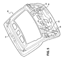
- Figure 5 is a perspective view of an inner panel used for a composite liftgate system, according to the present invention.
- Figure 6 is a rear view of an inner panel used for a composite liftgate system, according to the present invention.
- Figure 7 is a front view of an inner panel used for a composite liftgate system, according to the present invention.
- Figure 8 is a side view of an inner panel used for a composite liftgate system, according to the present invention.
- Figure 9 is an exploded perspective view of a first embodiment of an outer panel used in a composite liftgate system, according to the present invention.
- Figure 10 is a perspective view of a second embodiment of an outer panel used in a composite liftgate system, according to a first embodiment of the present invention.
- the composite liftgate system of the present invention utilizes a wide reinforcing bracket along with a latch which aids in spreading the load applied to the bracket over a larger area.
- the wide reinforcement bracket adds more structure by attaching to the inner panel with structural adhesive or insert molding. Additionally, the wide reinforcing bracket is also tied into other reinforcing brackets with steel tethers. The other reinforcing brackets are also connected to a hinge system through the use of additional steel tethers.
- the steel tethers are in the form of cables, stampings, tubes, etc., which reinforce the composite gate and the latch system (which ties to the body) to a counter balance system and the hinge system (which also ties back into the body structure).
- the composite liftgate of the present invention provides the advantage over other inventions through the use of a wide steel reinforcement in the area of the latch.
- the wide steel reinforcement is installed with structural adhesive, or in another embodiment is insert molded for added structure.
- Mechanical fasteners are used as a temporary connection to hold the wide steel reinforcement in place until the structural adhesive sets up and cures.
- Tethers similar to the tethers mentioned above, tie the lower reinforcement in the latch area to other important reinforced areas that extend to other reinforcements and to the upper hinges that again tie into the metallic body structure.
- the liftgate includes an inner composite panel.
- the structure of the inner composite panel includes various shapes and ribs which transfer the load path up through key structural areas of the assembly.
- the inner panel is connected to an outer panel to form the composite liftgate of the present invention.
- the inner panel and outer panel are bonded together through the use of a urethane bonding.
- the inner panel provides structural support for the composite liftgate of the present invention not only through the shape of the inner panel as described above, but the material used to make the inner panel provides structural support as well.
- the inner panel is made of a structural thermoplastic, such as a polypropylene, a thermoset or thermoplastic such as a reinforced polypropylene (RPP), and is preferably a 40% glass-filled polypropylene.
- the outer panel is made of a typical thermoplastic used as a show surface, such as a thermoplastic polyolefin (TPO), and provides no significant structural support for the composite liftgate of the present invention.
- TPO thermoplastic polyolefin
- the liftgate 10 includes a bracket 12, which is connected to an inner panel 14.
- the bracket 12 is structurally bonded using an adhesive 16, but it is within the scope of the invention that the bracket 12 could be insert molded to connect the bracket 12 to the inner panel 14.
- a set of lower pillar reinforcements 18 and a set of upper pillar reinforcements 20 are connected to the inner panel 14 in a similar manner as the bracket 12.
- Each of the lower pillar reinforcements 18 are typically connected to a gas strut (not shown), and the upper pillar reinforcements are typically attached to a hinge system (not shown), with the hinge system and gas strut connected to a vehicle.
- the liftgate 10 of the present invention also includes a series of reinforcement members 22.
- the reinforcement members 22 will keep the liftgate 10 together even if the inner panel 14 becomes cracked or deformed from being subjected to an impact.
- the reinforcement members 22 are in the form of tethers 22.
- the tethers 22 may be braded stainless steel cable, stainless steel tubing, a rolled or stamped steel channel, or a wide webbing material, similar to what is used in common seat belts.
- first pair of channels or latch channels 24 Formed as part of the inner panel 14 are a first pair of channels or latch channels 24.
- the channels 24 run in a substantially diagonal pattern from the near the center of the bracket 12 to the lower pillar reinforcements 18. In this embodiment, the channels are 70mm wide and 70mm deep, but it is within the scope of the invention that other dimensions may be used as well.
- the two channels 24 shown in the Figures produce substantially a "V-pattern.”
- second channels 26 which are substantially perpendicular to the latch channels 24. Again, the additional channels 26 are 70mm wide and 70mm deep, but it is within the scope of the invention that other dimensions be used as well.
- the inner panel 14 also includes a pair of third channels, or side channels 28, which again are 70mm wide and 70mm deep, and provide further structural support for the inner panel 14.
- the side channels 28 extend along each side of the inner panel 14, and intersect the latch channels 24 respectively in the general area of the lower pillar reinforcements 18.
- ribs 30 are also formed as part of the inner panel 14, similar to the channels 24,26,28.
- the ribs 30 are incorporated into all of the channels 24,26,28, and improve the rigidity of the entire lift gate 10.
- the liftgate 10 also includes an outer panel, generally shown at 32 in Figures 9 and 10 .
- the outer panel 32 is connected to the inner panel 14 such that a cavity is formed between the inner panel 14 and outer panel 32.
- the outer panel 32 may be formed of two separate pieces, as shown in Figure 9 , or may be formed as a single piece, as shown in Figure 10 .
Landscapes
- Engineering & Computer Science (AREA)
- Mechanical Engineering (AREA)
- Body Structure For Vehicles (AREA)
Description
- The present invention relates to liftgates for automobiles. More specifically, the present invention relates to a composite liftgate system according to the preamble of claim 1. Such a system is known from
WO 98/42527 A - One of the current trends in the automobile industry is to lower vehicle weight to help achieve better fuel economy, thus helping to meet fuel economy standards and to offset the higher fuel prices. Another trend is that there is a broader range of vehicle models, which in turn reduces the volume of vehicles produced on a per model basis. Liftgates are traditionally made from stamped steel panels that are heavy and have a high tooling cost. Sheet Molding Compound (SMC) is an alternative to steel for the inner and outer panels of the liftgate. Using SMC has several manufacturing concerns related to the material and process. Steel and SMC liftgates have a mass penalty over thermoplastics. There are also styling restrictions with traditional sheet metal components. Thermoplastic composite type materials used for liftgate applications also have difficulty meeting customer performance specifications.
- Another concern with the manufacture of liftgates is that typical lifgates are manufactured as a relatively flat or smoothly contoured panel, with structural reinforcements such as ribs being added onto the panel. This will also add weight and increase manufacturing complexity as well.
- One solution to this problem has been the 2008 Nissan Murano composite liftgate system, which has helped to satisfy the weight savings and the tooling cost concerns, but utilizes a typical bolt in small steel reinforcement at the latch which secures one end of the liftgate to the vehicle. This does not meet the higher load requirements desired in some applications, such as the latch pull test
- Document
EP 1 120 303 A1 discloses a motor vehicle door comprising a reinforcement of plastics material hinged to the body of said vehicle and constituting a bodywork part for said door, said reinforcement forming a generally continuous track suitable for bearing in leak-tight manner against a sealing gasket carried by the body of said vehicle, the door being characterized in that said reinforcement forms a bottom panel defining a chamber with its open side facing towards said body, said chamber being bordered by a channel situated in the bottom portion of said door and having its concave side facing towards the outside of said door. - Accordingly, there exists a need for a composite liftgate which is both lightweight, as well as structurally sound enough to meet various load requirements.
- The present invention is a thermoplastic composite liftgate system with reinforcements in key areas to allow the system to meet performance requirements, while lowering the tooling investment, lowering the system mass, and improving the styling flexibility. The present ivention includes an inner panel, and at least one bracket, or reinforcement, connected to the inner panel such that when a force is applied to the bracket, the force is distributed to the inner panel.
- Further areas of applicability of the present invention will become apparent from the detailed description provided hereinafter. It should be understood that the detailed description and specific examples, while indicating the preferred embodiment of the invention, are intended for purposes of illustration only and are not intended to limit the scope of the invention.
- The present invention will become more fully understood from the detailed description and the accompanying drawings, wherein:
-
Figure 1 is a rear view of an inner panel having multiple reinforcements used in a liftgate system, according to the present invention; -
Figure 2 is an enlarged perspective view of a lower pillar reinforcement used for a composite liftgate system, according to the present invention; -
Figure 3 is an enlarged perspective view of an upper pillar reinforcement used for a composite liftgate system, according to the present invention; -
Figure 4 is an enlarged perspective view of a wide reinforcing bracket used for a composite liftgate system, according to the present invention; -
Figure 5 is a perspective view of an inner panel used for a composite liftgate system, according to the present invention; -
Figure 6 is a rear view of an inner panel used for a composite liftgate system, according to the present invention; -
Figure 7 is a front view of an inner panel used for a composite liftgate system, according to the present invention; -
Figure 8 is a side view of an inner panel used for a composite liftgate system, according to the present invention; -
Figure 9 is an exploded perspective view of a first embodiment of an outer panel used in a composite liftgate system, according to the present invention; and -
Figure 10 is a perspective view of a second embodiment of an outer panel used in a composite liftgate system, according to a first embodiment of the present invention. - The following description of the preferred embodiment(s) is merely exemplary in nature and is in no way intended to limit the invention, its application, or uses.
- The composite liftgate system of the present invention utilizes a wide reinforcing bracket along with a latch which aids in spreading the load applied to the bracket over a larger area. The wide reinforcement bracket adds more structure by attaching to the inner panel with structural adhesive or insert molding. Additionally, the wide reinforcing bracket is also tied into other reinforcing brackets with steel tethers. The other reinforcing brackets are also connected to a hinge system through the use of additional steel tethers. The steel tethers are in the form of cables, stampings, tubes, etc., which reinforce the composite gate and the latch system (which ties to the body) to a counter balance system and the hinge system (which also ties back into the body structure).
- The composite liftgate of the present invention provides the advantage over other inventions through the use of a wide steel reinforcement in the area of the latch. The wide steel reinforcement is installed with structural adhesive, or in another embodiment is insert molded for added structure. Mechanical fasteners are used as a temporary connection to hold the wide steel reinforcement in place until the structural adhesive sets up and cures. Tethers, similar to the tethers mentioned above, tie the lower reinforcement in the latch area to other important reinforced areas that extend to other reinforcements and to the upper hinges that again tie into the metallic body structure.
- Another feature of the present invention is that the liftgate includes an inner composite panel. The structure of the inner composite panel includes various shapes and ribs which transfer the load path up through key structural areas of the assembly.
- The inner panel is connected to an outer panel to form the composite liftgate of the present invention. The inner panel and outer panel are bonded together through the use of a urethane bonding. The inner panel provides structural support for the composite liftgate of the present invention not only through the shape of the inner panel as described above, but the material used to make the inner panel provides structural support as well. The inner panel is made of a structural thermoplastic, such as a polypropylene, a thermoset or thermoplastic such as a reinforced polypropylene (RPP), and is preferably a 40% glass-filled polypropylene. The outer panel is made of a typical thermoplastic used as a show surface, such as a thermoplastic polyolefin (TPO), and provides no significant structural support for the composite liftgate of the present invention.
- An embodiment of a composite liftgate system is shown in the Figures generally at 10. The
liftgate 10 includes abracket 12, which is connected to aninner panel 14. In this embodiment, thebracket 12 is structurally bonded using anadhesive 16, but it is within the scope of the invention that thebracket 12 could be insert molded to connect thebracket 12 to theinner panel 14. - Also connected to the
inner panel 14 are a set oflower pillar reinforcements 18 and a set ofupper pillar reinforcements 20; both thereinforcements inner panel 14 in a similar manner as thebracket 12. Each of thelower pillar reinforcements 18 are typically connected to a gas strut (not shown), and the upper pillar reinforcements are typically attached to a hinge system (not shown), with the hinge system and gas strut connected to a vehicle. - The
liftgate 10 of the present invention also includes a series ofreinforcement members 22. Thereinforcement members 22 will keep theliftgate 10 together even if theinner panel 14 becomes cracked or deformed from being subjected to an impact. In this embodiment, thereinforcement members 22 are in the form oftethers 22. Thetethers 22 may be braded stainless steel cable, stainless steel tubing, a rolled or stamped steel channel, or a wide webbing material, similar to what is used in common seat belts. - Formed as part of the
inner panel 14 are a first pair of channels orlatch channels 24. Thechannels 24 run in a substantially diagonal pattern from the near the center of thebracket 12 to thelower pillar reinforcements 18. In this embodiment, the channels are 70mm wide and 70mm deep, but it is within the scope of the invention that other dimensions may be used as well. The twochannels 24 shown in the Figures produce substantially a "V-pattern." - There are also two
second channels 26 which are substantially perpendicular to thelatch channels 24. Again, theadditional channels 26 are 70mm wide and 70mm deep, but it is within the scope of the invention that other dimensions be used as well. - The
inner panel 14 also includes a pair of third channels, orside channels 28, which again are 70mm wide and 70mm deep, and provide further structural support for theinner panel 14. Theside channels 28 extend along each side of theinner panel 14, and intersect thelatch channels 24 respectively in the general area of thelower pillar reinforcements 18. - To further improve the structural integrity of the
inner panel 14, there is also a plurality of secondary reinforcement members, orribs 30. Theribs 30 are also formed as part of theinner panel 14, similar to thechannels ribs 30 are incorporated into all of thechannels entire lift gate 10. - The
liftgate 10 also includes an outer panel, generally shown at 32 inFigures 9 and 10 . Theouter panel 32 is connected to theinner panel 14 such that a cavity is formed between theinner panel 14 andouter panel 32. Theouter panel 32 may be formed of two separate pieces, as shown inFigure 9 , or may be formed as a single piece, as shown inFigure 10 . - The description of the invention is merely exemplary in nature. The invention is only limited by the scope of the appended claims.
Claims (11)
- A composite liftgate system, comprising:an inner panel (14); anda bracket (12) connected to said inner panel (14) such that when a force is applied to said bracket (12), the force is distributed to said inner panel (14); characterized byat least one lower pillar reinforcement (18) connected to said inner panel (14) for increasing the structural integrity of said inner panel (14);at least one upper pillar reinforcement (20) connected to said inner panel (14) for increasing the structural integrity of said inner panel (14); andat least one tether (22) for connecting said at least one lower pillar reinforcement (18) to said at least one upper pillar reinforcement (20), and for connecting said at least one lower pillar reinforcement (18) to said bracket (12), such that when said inner panel (14) becomes cracked or deformed, said at least one tether (22) will maintain a connection between said at least one lower pillar reinforcement (18) and said at least one upper pillar reinforcement (20), and maintain a connection between said at least one lower pillar reinforcement and said bracket (12).
- The composite lift gate system of claim 1, further comprising an outer panel (32) connected to said inner panel (14), wherein said lower pillar reinforcement (18), said upper pillar reinforcement (20), and said at least one tether (22) are disposed between said inner panel (14) and said outer panel (32) when said inner panel (14) is connected to said outer panel (32).
- The composite lift gate system of claim 1, further comprising:at least one latch channel (24) extending along side inner panel from near the center of said bracket (12) to said at least one lower pillar rein-forcement (18);at least one channel (26) extending along said inner panel (14) and substantially perpendicular to said at least one latch channel (24); andat least one side channel (28) extending along an outer portion of said inner panel (14), said at least one side channel (28) being intersected by said at least one latch channel (24).
- The composite lift gate system of claim 3, further comprising a plurality of secondary reinforcement members, a portion of said plurality of secondary reinforcement members disposed in said at least one latch channel (24), a portion of said plurality of secondary reinforcement members disposed in said at least one channel (26), and a portion of said plurality of secondary reinforcement members disposed in said at least one side channel (28).
- The composite liftgate system of claim 2, wherein the bracket (12) is positioned between said inner panel (14) and said outer panel (32).
- The composite lift gate system of claim 3, wherein
a plurality of ribs (30) provides support for each of said at least one latch channel (24), said at least one channel (26), and said at least one side channel (28), wherein at least one of said plurality of ribs (30) is formed as part of said at least one latch channel (24), at least one of said plurality of ribs (30) is formed as part of said at least one channel (26), and at least one of said plurality of ribs (30) is formed as part of said at least one side channel (28). - The composite lift gate system of claim 1, said at least one tether (22) being one selected from the group consisting of braded stainless steel cable, stainless steel tubing, a rolled or stamped steel channel, and a wide webbing material.
- The composite lift gate system of claim 3 or 6 wherein said at least one latch channel (24) is substantially 70 millimeters wide and substantially 70 millimeters deep, and/or
said at least one channel (26) is substantially 70 millimeters wide and substantially 70 millimeters deep, and/or
said at least one side channel (28) is substantially 70 millimeters wide and substantially 70 millimeters deep. - The composite lift gate system of any one of the preceding claims, wherein the bracket (12), said at least one lower pillar reinforcement (18), and/or said at least one upper and/or lower pillar reinforcement (18,20) are connected to said inner panel (14) through the use of a structural adhesive and/or the use of insert molding, respectively.
- The composite lift gate system of claim 4, said plurality of secondary reinforcement members further comprising a plurality of ribs (30).
- The composite lift gate system of claim 1 or 5, said bracket (12) connected to said inner panel (14) further corresponding to a wide reinforcing bracket (12) being operable for spreading said force applied to said wide reinforcing bracket (12) to said inner panel (14).
Applications Claiming Priority (2)
| Application Number | Priority Date | Filing Date | Title |
|---|---|---|---|
| US13048908P | 2008-05-30 | 2008-05-30 | |
| PCT/CA2009/000747 WO2009143627A1 (en) | 2008-05-30 | 2009-06-01 | Composite liftgate system |
Publications (3)
| Publication Number | Publication Date |
|---|---|
| EP2293953A1 EP2293953A1 (en) | 2011-03-16 |
| EP2293953A4 EP2293953A4 (en) | 2011-08-24 |
| EP2293953B1 true EP2293953B1 (en) | 2013-02-13 |
Family
ID=41376522
Family Applications (1)
| Application Number | Title | Priority Date | Filing Date |
|---|---|---|---|
| EP09753388A Not-in-force EP2293953B1 (en) | 2008-05-30 | 2009-06-01 | Composite liftgate system |
Country Status (4)
| Country | Link |
|---|---|
| US (1) | US8403399B2 (en) |
| EP (1) | EP2293953B1 (en) |
| CA (1) | CA2723759C (en) |
| WO (1) | WO2009143627A1 (en) |
Families Citing this family (44)
| Publication number | Priority date | Publication date | Assignee | Title |
|---|---|---|---|---|
| FR2922859B1 (en) * | 2007-10-31 | 2010-02-19 | Plastic Omnium Cie | ASSEMBLY OF A TAILGATE AND A PIECE INTENDED TO BE REPORTED ON THE HOUSING |
| FR2953770B1 (en) * | 2009-12-16 | 2011-11-25 | Renault Sas | TRUNK DOOR FOR MOTOR VEHICLE |
| JP5769005B2 (en) * | 2011-05-13 | 2015-08-26 | 日立化成株式会社 | Automotive back door |
| JP5360156B2 (en) * | 2011-08-01 | 2013-12-04 | トヨタ自動車株式会社 | Vehicle back door structure |
| JP5760926B2 (en) * | 2011-10-05 | 2015-08-12 | トヨタ自動車株式会社 | Opening and closing body structure for vehicles |
| JP6049390B2 (en) * | 2012-10-17 | 2016-12-21 | ダイキョーニシカワ株式会社 | Vehicle back door |
| EP2908997B1 (en) * | 2012-10-19 | 2022-03-16 | Magna International Inc. | Co-injection molding of the structural portion of a vehicle liftgate inner panel |
| FR3010351B1 (en) * | 2013-09-06 | 2017-07-14 | Plastic Omnium Cie | INTERIOR HOUSING FOR VEHICLE HATCH, WITH TECHNICAL PANEL REPORTED |
| KR102374628B1 (en) * | 2013-10-07 | 2022-03-15 | 사빅 글로벌 테크놀러지스 비.브이. | Closed section geometry, hollow shape, vehicle components |
| US8899658B1 (en) | 2013-11-21 | 2014-12-02 | Ford Global Technologies, Llc | Liftgate hinge reinforcement |
| WO2015123312A1 (en) * | 2014-02-11 | 2015-08-20 | Magna International Inc. | Composite liftgate |
| WO2015123295A1 (en) * | 2014-02-11 | 2015-08-20 | Magna International Inc. | Composite liftgate |
| CN207141197U (en) | 2014-08-12 | 2018-03-27 | 德韧营运有限责任公司 | Composite rear sill module |
| JP6036776B2 (en) * | 2014-09-22 | 2016-11-30 | トヨタ自動車株式会社 | Assembly method of resin back door for vehicle |
| US9409468B2 (en) | 2014-12-19 | 2016-08-09 | Fca Us Llc | Liftgate inner die cast with integrated glass urethane bonding surface |
| JP6252507B2 (en) | 2015-02-12 | 2017-12-27 | トヨタ自動車株式会社 | Vehicle exterior member and vehicle back door |
| FR3040660B1 (en) * | 2015-09-03 | 2019-01-25 | Faurecia Bloc Avant | METHOD FOR MANUFACTURING A PANEL OF A VEHICLE TAIL AND ASSOCIATED PANEL |
| JP6323417B2 (en) * | 2015-09-04 | 2018-05-16 | トヨタ自動車株式会社 | Vehicle back door structure |
| WO2017042699A1 (en) | 2015-09-07 | 2017-03-16 | Sabic Global Technologies B.V. | Molding of plastic glazing of tailgates |
| WO2017042698A1 (en) | 2015-09-07 | 2017-03-16 | Sabic Global Technologies B.V. | Surfaces of plastic glazing of tailgates |
| US10690314B2 (en) | 2015-09-07 | 2020-06-23 | Sabic Global Technologies B.V. | Lighting systems of tailgates with plastic glazing |
| EP3347219B1 (en) | 2015-09-07 | 2021-04-14 | SABIC Global Technologies B.V. | Aerodynamic features of plastic glazing of tailgates |
| KR102215029B1 (en) | 2015-11-23 | 2021-02-15 | 사빅 글로벌 테크놀러지스 비.브이. | Lighting system for windows having plastic glazing |
| JP6322179B2 (en) * | 2015-12-16 | 2018-05-09 | 本田技研工業株式会社 | Tailgate structure |
| USD829138S1 (en) * | 2016-03-18 | 2018-09-25 | China-Euro Vehicle Technology Aktiebolag | Engine hood for a vehicle |
| JP6973579B2 (en) * | 2016-09-08 | 2021-12-01 | スズキ株式会社 | Vehicle back door structure |
| US9834072B1 (en) | 2016-09-21 | 2017-12-05 | Ford Global Technologies, Llc | Liftgate assembly for a vehicle |
| CA3039006A1 (en) * | 2016-10-06 | 2018-04-12 | Magna Exteriors Inc. | Liftgate reinforcement arrangements |
| CN110418726B (en) * | 2017-02-16 | 2023-05-23 | 麦格纳外饰公司 | Infrared welded lifting door assembly and manufacturing method thereof |
| JP6957796B2 (en) * | 2017-03-30 | 2021-11-02 | ダイハツ工業株式会社 | Backdoor inner panel for vehicles |
| US11634013B2 (en) | 2017-06-30 | 2023-04-25 | Magna Exteriors, Inc. | Liftgate reinforcement arrangements |
| JP6495416B2 (en) * | 2017-10-27 | 2019-04-03 | ダイハツ工業株式会社 | Resin back door reinforcement structure |
| JP6495417B2 (en) * | 2017-10-30 | 2019-04-03 | ダイハツ工業株式会社 | Resin back door reinforcement structure |
| JP6966314B2 (en) * | 2017-12-19 | 2021-11-17 | トヨタ自動車株式会社 | Vehicle resin back door and its manufacturing method |
| JP6974157B2 (en) * | 2017-12-21 | 2021-12-01 | トヨタ自動車株式会社 | Vehicle resin back door |
| JP6966316B2 (en) * | 2017-12-21 | 2021-11-17 | トヨタ自動車株式会社 | Vehicle resin back door |
| CN108116205B (en) * | 2018-01-10 | 2024-03-29 | 延锋彼欧汽车外饰系统有限公司 | Reinforcement for vehicle back door inner plate |
| EP3844008A1 (en) * | 2018-11-09 | 2021-07-07 | Magna Exteriors Inc. | A thermoplastic liftgate arrangement having blow molded reinforcements |
| CN114599536B (en) | 2019-06-21 | 2024-10-01 | 麦格纳外饰公司 | Metal rib overmolded joints |
| FR3098750B1 (en) * | 2019-07-15 | 2023-01-13 | Cie Plastic Omnium Se | Reinforcement insert with through holes |
| WO2021052114A1 (en) * | 2019-09-19 | 2021-03-25 | 宁波信泰机械有限公司 | High-integration-level plastic tail door |
| DE102019216518B3 (en) * | 2019-10-25 | 2021-03-25 | Magna Exteriors Gmbh | Vehicle door and its method for producing a vehicle door |
| US11492051B2 (en) | 2020-07-09 | 2022-11-08 | Toyota Motor Engineering & Manufacturing North America Inc. | Resin panel spacer block for energy absorption, load support, and gap prevention |
| USD1089023S1 (en) * | 2023-08-17 | 2025-08-19 | Hyundai Motor Company | Tailgate panel for an automobile |
Family Cites Families (19)
| Publication number | Priority date | Publication date | Assignee | Title |
|---|---|---|---|---|
| US3851867A (en) * | 1973-07-09 | 1974-12-03 | Gen Motors Corp | Pneumatic actuator control apparatus |
| GB2078628B (en) | 1980-05-21 | 1984-03-07 | British Aluminium Co Ltd | Load bearing panels |
| DE3637622A1 (en) * | 1986-11-05 | 1988-05-19 | Ford Werke Ag | DOUBLE-WALLED PLASTIC BODY COMPONENT FOR MOTOR VEHICLES |
| US5181759A (en) * | 1992-02-21 | 1993-01-26 | General Motors Corporation | Collapsible arm rest |
| US5449213A (en) * | 1993-05-26 | 1995-09-12 | Aluminum Company Of America | Movable body panel for a vehicle and related method |
| US6019418A (en) * | 1997-07-31 | 2000-02-01 | Lear Corporation | Modular vehicle liftgate module |
| WO1998042527A1 (en) | 1997-03-25 | 1998-10-01 | Lear Corporation | Modular vehicle liftgate assembly |
| US5944373A (en) | 1998-08-18 | 1999-08-31 | Aluminum Company Of America | Lightweight tailgate assembly |
| FR2804070B1 (en) | 2000-01-26 | 2002-09-20 | Inoplast Sa | VEHICLE OPENING MADE OF PLASTIC MATERIAL AND MOTOR VEHICLE EQUIPPED WITH SUCH AN OPENING |
| TW593005B (en) * | 2001-03-13 | 2004-06-21 | Kikuchi Press Industry Co Ltd | Door for vehicle and its manufacturing method |
| US6860537B2 (en) * | 2001-12-05 | 2005-03-01 | Alcoa Inc. | Door for a motor vehicle |
| US6988757B2 (en) * | 2002-08-28 | 2006-01-24 | Dow Global Technologies Inc. | Composite panel and method of forming the same |
| WO2005042287A1 (en) * | 2003-10-23 | 2005-05-12 | Magna International Inc. | Liftgate frame |
| DE202004011851U1 (en) | 2004-07-28 | 2004-09-30 | Peguform Gmbh & Co. Kg | Automotive rear door |
| JP4255947B2 (en) | 2005-12-28 | 2009-04-22 | 本田技研工業株式会社 | Rear door structure and rear door assembly method |
| EP1813454B1 (en) * | 2006-01-26 | 2012-04-18 | Honda Motor Co., Ltd. | Hatchback door structure for vehicles |
| JP4482532B2 (en) * | 2006-03-09 | 2010-06-16 | 本田技研工業株式会社 | Vehicle rear door structure |
| US7618083B2 (en) * | 2006-08-02 | 2009-11-17 | Honda Motor Co., Ltd. | Rear door structure for vehicle |
| KR20090044183A (en) * | 2007-10-31 | 2009-05-07 | 기아자동차주식회사 | Tailgate structure of the vehicle |
-
2009
- 2009-06-01 CA CA2723759A patent/CA2723759C/en active Active
- 2009-06-01 US US12/992,163 patent/US8403399B2/en active Active
- 2009-06-01 EP EP09753388A patent/EP2293953B1/en not_active Not-in-force
- 2009-06-01 WO PCT/CA2009/000747 patent/WO2009143627A1/en not_active Ceased
Also Published As
| Publication number | Publication date |
|---|---|
| US20110074179A1 (en) | 2011-03-31 |
| CA2723759A1 (en) | 2009-12-03 |
| US8403399B2 (en) | 2013-03-26 |
| EP2293953A1 (en) | 2011-03-16 |
| WO2009143627A1 (en) | 2009-12-03 |
| EP2293953A4 (en) | 2011-08-24 |
| CA2723759C (en) | 2016-07-19 |
Similar Documents
| Publication | Publication Date | Title |
|---|---|---|
| CA2723759C (en) | Composite liftgate system | |
| US7125067B2 (en) | Magnesium door assembly for automobiles | |
| US6779830B2 (en) | Anti-intrusion beam for a vehicle door assembly | |
| US9283702B2 (en) | Door for a motor vehicle and method for the production thereof | |
| EP4032733B1 (en) | Composite liftgate | |
| EP3107746B1 (en) | Composite liftgate | |
| EP2899067B1 (en) | Hybrid seat frame for vehicle | |
| US10793201B1 (en) | Pickup truck cargo box subassembly | |
| US20040164580A1 (en) | Lightweight composite tailgate | |
| JP4421616B2 (en) | Plastic panel | |
| US11305822B2 (en) | Liftgate arrangement having a carbon fiber reinforced sheet molding compound reinforcement | |
| US8727422B2 (en) | Back door for automobile | |
| US6457768B1 (en) | Two-piece vehicle hardtop having an integral structural headliner | |
| CN100595100C (en) | Hybrid construction's assembly bracket | |
| CN101269621A (en) | Roof frames for motor vehicles | |
| US20210347235A1 (en) | A thermoplastic liftgate arrangement having blow molded reinforcements | |
| JP4093124B2 (en) | Center pillar structure of automobile | |
| US11117627B2 (en) | Overmolded vehicle sheet metal structures with integrated attachments | |
| CN212889806U (en) | Automobile back door assembly and vehicle | |
| US20240424876A1 (en) | Liftgate with bulkhead reinforcements | |
| CN220701202U (en) | Vehicle safety A post structure | |
| CN116080771B (en) | Automobile trunk cover | |
| EP4090580A1 (en) | Pickup truck cargo box subassembly | |
| CN212637669U (en) | Car B post and car | |
| JP3699186B2 (en) | Reinforcement and decoration members for vehicles |
Legal Events
| Date | Code | Title | Description |
|---|---|---|---|
| PUAI | Public reference made under article 153(3) epc to a published international application that has entered the european phase |
Free format text: ORIGINAL CODE: 0009012 |
|
| 17P | Request for examination filed |
Effective date: 20101221 |
|
| AK | Designated contracting states |
Kind code of ref document: A1 Designated state(s): AT BE BG CH CY CZ DE DK EE ES FI FR GB GR HR HU IE IS IT LI LT LU LV MC MK MT NL NO PL PT RO SE SI SK TR |
|
| AX | Request for extension of the european patent |
Extension state: AL BA RS |
|
| A4 | Supplementary search report drawn up and despatched |
Effective date: 20110722 |
|
| RIC1 | Information provided on ipc code assigned before grant |
Ipc: B60J 5/10 20060101AFI20110718BHEP Ipc: B62D 29/04 20060101ALI20110718BHEP Ipc: B62D 33/027 20060101ALI20110718BHEP |
|
| DAX | Request for extension of the european patent (deleted) | ||
| GRAP | Despatch of communication of intention to grant a patent |
Free format text: ORIGINAL CODE: EPIDOSNIGR1 |
|
| GRAS | Grant fee paid |
Free format text: ORIGINAL CODE: EPIDOSNIGR3 |
|
| GRAA | (expected) grant |
Free format text: ORIGINAL CODE: 0009210 |
|
| AK | Designated contracting states |
Kind code of ref document: B1 Designated state(s): AT BE BG CH CY CZ DE DK EE ES FI FR GB GR HR HU IE IS IT LI LT LU LV MC MK MT NL NO PL PT RO SE SI SK TR |
|
| REG | Reference to a national code |
Ref country code: GB Ref legal event code: FG4D |
|
| REG | Reference to a national code |
Ref country code: AT Ref legal event code: REF Ref document number: 596274 Country of ref document: AT Kind code of ref document: T Effective date: 20130215 |
|
| REG | Reference to a national code |
Ref country code: IE Ref legal event code: FG4D |
|
| REG | Reference to a national code |
Ref country code: DE Ref legal event code: R096 Ref document number: 602009013285 Country of ref document: DE Effective date: 20130411 |
|
| REG | Reference to a national code |
Ref country code: AT Ref legal event code: MK05 Ref document number: 596274 Country of ref document: AT Kind code of ref document: T Effective date: 20130213 |
|
| REG | Reference to a national code |
Ref country code: NL Ref legal event code: VDEP Effective date: 20130213 |
|
| REG | Reference to a national code |
Ref country code: LT Ref legal event code: MG4D |
|
| PG25 | Lapsed in a contracting state [announced via postgrant information from national office to epo] |
Ref country code: AT Free format text: LAPSE BECAUSE OF FAILURE TO SUBMIT A TRANSLATION OF THE DESCRIPTION OR TO PAY THE FEE WITHIN THE PRESCRIBED TIME-LIMIT Effective date: 20130213 Ref country code: LT Free format text: LAPSE BECAUSE OF FAILURE TO SUBMIT A TRANSLATION OF THE DESCRIPTION OR TO PAY THE FEE WITHIN THE PRESCRIBED TIME-LIMIT Effective date: 20130213 Ref country code: SE Free format text: LAPSE BECAUSE OF FAILURE TO SUBMIT A TRANSLATION OF THE DESCRIPTION OR TO PAY THE FEE WITHIN THE PRESCRIBED TIME-LIMIT Effective date: 20130213 Ref country code: BG Free format text: LAPSE BECAUSE OF FAILURE TO SUBMIT A TRANSLATION OF THE DESCRIPTION OR TO PAY THE FEE WITHIN THE PRESCRIBED TIME-LIMIT Effective date: 20130513 Ref country code: ES Free format text: LAPSE BECAUSE OF FAILURE TO SUBMIT A TRANSLATION OF THE DESCRIPTION OR TO PAY THE FEE WITHIN THE PRESCRIBED TIME-LIMIT Effective date: 20130524 Ref country code: IS Free format text: LAPSE BECAUSE OF FAILURE TO SUBMIT A TRANSLATION OF THE DESCRIPTION OR TO PAY THE FEE WITHIN THE PRESCRIBED TIME-LIMIT Effective date: 20130613 Ref country code: NO Free format text: LAPSE BECAUSE OF FAILURE TO SUBMIT A TRANSLATION OF THE DESCRIPTION OR TO PAY THE FEE WITHIN THE PRESCRIBED TIME-LIMIT Effective date: 20130513 |
|
| PG25 | Lapsed in a contracting state [announced via postgrant information from national office to epo] |
Ref country code: PT Free format text: LAPSE BECAUSE OF FAILURE TO SUBMIT A TRANSLATION OF THE DESCRIPTION OR TO PAY THE FEE WITHIN THE PRESCRIBED TIME-LIMIT Effective date: 20130613 Ref country code: PL Free format text: LAPSE BECAUSE OF FAILURE TO SUBMIT A TRANSLATION OF THE DESCRIPTION OR TO PAY THE FEE WITHIN THE PRESCRIBED TIME-LIMIT Effective date: 20130213 Ref country code: GR Free format text: LAPSE BECAUSE OF FAILURE TO SUBMIT A TRANSLATION OF THE DESCRIPTION OR TO PAY THE FEE WITHIN THE PRESCRIBED TIME-LIMIT Effective date: 20130514 Ref country code: FI Free format text: LAPSE BECAUSE OF FAILURE TO SUBMIT A TRANSLATION OF THE DESCRIPTION OR TO PAY THE FEE WITHIN THE PRESCRIBED TIME-LIMIT Effective date: 20130213 Ref country code: BE Free format text: LAPSE BECAUSE OF FAILURE TO SUBMIT A TRANSLATION OF THE DESCRIPTION OR TO PAY THE FEE WITHIN THE PRESCRIBED TIME-LIMIT Effective date: 20130213 Ref country code: LV Free format text: LAPSE BECAUSE OF FAILURE TO SUBMIT A TRANSLATION OF THE DESCRIPTION OR TO PAY THE FEE WITHIN THE PRESCRIBED TIME-LIMIT Effective date: 20130213 Ref country code: SI Free format text: LAPSE BECAUSE OF FAILURE TO SUBMIT A TRANSLATION OF THE DESCRIPTION OR TO PAY THE FEE WITHIN THE PRESCRIBED TIME-LIMIT Effective date: 20130213 |
|
| PG25 | Lapsed in a contracting state [announced via postgrant information from national office to epo] |
Ref country code: HR Free format text: LAPSE BECAUSE OF FAILURE TO SUBMIT A TRANSLATION OF THE DESCRIPTION OR TO PAY THE FEE WITHIN THE PRESCRIBED TIME-LIMIT Effective date: 20130213 |
|
| PG25 | Lapsed in a contracting state [announced via postgrant information from national office to epo] |
Ref country code: EE Free format text: LAPSE BECAUSE OF FAILURE TO SUBMIT A TRANSLATION OF THE DESCRIPTION OR TO PAY THE FEE WITHIN THE PRESCRIBED TIME-LIMIT Effective date: 20130213 Ref country code: DK Free format text: LAPSE BECAUSE OF FAILURE TO SUBMIT A TRANSLATION OF THE DESCRIPTION OR TO PAY THE FEE WITHIN THE PRESCRIBED TIME-LIMIT Effective date: 20130213 Ref country code: CZ Free format text: LAPSE BECAUSE OF FAILURE TO SUBMIT A TRANSLATION OF THE DESCRIPTION OR TO PAY THE FEE WITHIN THE PRESCRIBED TIME-LIMIT Effective date: 20130213 Ref country code: NL Free format text: LAPSE BECAUSE OF FAILURE TO SUBMIT A TRANSLATION OF THE DESCRIPTION OR TO PAY THE FEE WITHIN THE PRESCRIBED TIME-LIMIT Effective date: 20130213 Ref country code: SK Free format text: LAPSE BECAUSE OF FAILURE TO SUBMIT A TRANSLATION OF THE DESCRIPTION OR TO PAY THE FEE WITHIN THE PRESCRIBED TIME-LIMIT Effective date: 20130213 Ref country code: RO Free format text: LAPSE BECAUSE OF FAILURE TO SUBMIT A TRANSLATION OF THE DESCRIPTION OR TO PAY THE FEE WITHIN THE PRESCRIBED TIME-LIMIT Effective date: 20130213 |
|
| PLBE | No opposition filed within time limit |
Free format text: ORIGINAL CODE: 0009261 |
|
| STAA | Information on the status of an ep patent application or granted ep patent |
Free format text: STATUS: NO OPPOSITION FILED WITHIN TIME LIMIT |
|
| PG25 | Lapsed in a contracting state [announced via postgrant information from national office to epo] |
Ref country code: IT Free format text: LAPSE BECAUSE OF FAILURE TO SUBMIT A TRANSLATION OF THE DESCRIPTION OR TO PAY THE FEE WITHIN THE PRESCRIBED TIME-LIMIT Effective date: 20130213 |
|
| 26N | No opposition filed |
Effective date: 20131114 |
|
| PG25 | Lapsed in a contracting state [announced via postgrant information from national office to epo] |
Ref country code: MC Free format text: LAPSE BECAUSE OF FAILURE TO SUBMIT A TRANSLATION OF THE DESCRIPTION OR TO PAY THE FEE WITHIN THE PRESCRIBED TIME-LIMIT Effective date: 20130213 |
|
| REG | Reference to a national code |
Ref country code: CH Ref legal event code: PL |
|
| REG | Reference to a national code |
Ref country code: DE Ref legal event code: R097 Ref document number: 602009013285 Country of ref document: DE Effective date: 20131114 |
|
| REG | Reference to a national code |
Ref country code: IE Ref legal event code: MM4A |
|
| PG25 | Lapsed in a contracting state [announced via postgrant information from national office to epo] |
Ref country code: LI Free format text: LAPSE BECAUSE OF NON-PAYMENT OF DUE FEES Effective date: 20130630 Ref country code: IE Free format text: LAPSE BECAUSE OF NON-PAYMENT OF DUE FEES Effective date: 20130601 Ref country code: CH Free format text: LAPSE BECAUSE OF NON-PAYMENT OF DUE FEES Effective date: 20130630 |
|
| PG25 | Lapsed in a contracting state [announced via postgrant information from national office to epo] |
Ref country code: MT Free format text: LAPSE BECAUSE OF FAILURE TO SUBMIT A TRANSLATION OF THE DESCRIPTION OR TO PAY THE FEE WITHIN THE PRESCRIBED TIME-LIMIT Effective date: 20130213 |
|
| PG25 | Lapsed in a contracting state [announced via postgrant information from national office to epo] |
Ref country code: TR Free format text: LAPSE BECAUSE OF FAILURE TO SUBMIT A TRANSLATION OF THE DESCRIPTION OR TO PAY THE FEE WITHIN THE PRESCRIBED TIME-LIMIT Effective date: 20130213 Ref country code: CY Free format text: LAPSE BECAUSE OF FAILURE TO SUBMIT A TRANSLATION OF THE DESCRIPTION OR TO PAY THE FEE WITHIN THE PRESCRIBED TIME-LIMIT Effective date: 20130213 |
|
| PG25 | Lapsed in a contracting state [announced via postgrant information from national office to epo] |
Ref country code: HU Free format text: LAPSE BECAUSE OF FAILURE TO SUBMIT A TRANSLATION OF THE DESCRIPTION OR TO PAY THE FEE WITHIN THE PRESCRIBED TIME-LIMIT; INVALID AB INITIO Effective date: 20090601 Ref country code: LU Free format text: LAPSE BECAUSE OF NON-PAYMENT OF DUE FEES Effective date: 20130601 Ref country code: MK Free format text: LAPSE BECAUSE OF FAILURE TO SUBMIT A TRANSLATION OF THE DESCRIPTION OR TO PAY THE FEE WITHIN THE PRESCRIBED TIME-LIMIT Effective date: 20130213 |
|
| REG | Reference to a national code |
Ref country code: FR Ref legal event code: PLFP Year of fee payment: 8 |
|
| REG | Reference to a national code |
Ref country code: DE Ref legal event code: R082 Ref document number: 602009013285 Country of ref document: DE Representative=s name: GLAWE DELFS MOLL PARTNERSCHAFT MBB VON PATENT-, DE |
|
| REG | Reference to a national code |
Ref country code: FR Ref legal event code: PLFP Year of fee payment: 9 |
|
| REG | Reference to a national code |
Ref country code: FR Ref legal event code: PLFP Year of fee payment: 10 |
|
| REG | Reference to a national code |
Ref country code: FR Ref legal event code: PLFP Year of fee payment: 15 |
|
| P01 | Opt-out of the competence of the unified patent court (upc) registered |
Effective date: 20230517 |
|
| PGFP | Annual fee paid to national office [announced via postgrant information from national office to epo] |
Ref country code: FR Payment date: 20240328 Year of fee payment: 16 |
|
| PGFP | Annual fee paid to national office [announced via postgrant information from national office to epo] |
Ref country code: GB Payment date: 20240402 Year of fee payment: 16 |
|
| PGFP | Annual fee paid to national office [announced via postgrant information from national office to epo] |
Ref country code: DE Payment date: 20240328 Year of fee payment: 16 |
|
| REG | Reference to a national code |
Ref country code: DE Ref legal event code: R082 Ref document number: 602009013285 Country of ref document: DE Representative=s name: WITTE, WELLER & PARTNER PATENTANWAELTE MBB, DE |
|
| REG | Reference to a national code |
Ref country code: DE Ref legal event code: R119 Ref document number: 602009013285 Country of ref document: DE |
|
| GBPC | Gb: european patent ceased through non-payment of renewal fee |
Effective date: 20250601 |
|
| PG25 | Lapsed in a contracting state [announced via postgrant information from national office to epo] |
Ref country code: GB Free format text: LAPSE BECAUSE OF NON-PAYMENT OF DUE FEES Effective date: 20250601 |
|
| PG25 | Lapsed in a contracting state [announced via postgrant information from national office to epo] |
Ref country code: DE Free format text: LAPSE BECAUSE OF NON-PAYMENT OF DUE FEES Effective date: 20260101 |
|
| PG25 | Lapsed in a contracting state [announced via postgrant information from national office to epo] |
Ref country code: FR Free format text: LAPSE BECAUSE OF NON-PAYMENT OF DUE FEES Effective date: 20250630 |