EP2293843B1 - Methods and systems for guiding radiotherapy setups - Google Patents
Methods and systems for guiding radiotherapy setups Download PDFInfo
- Publication number
- EP2293843B1 EP2293843B1 EP09756994A EP09756994A EP2293843B1 EP 2293843 B1 EP2293843 B1 EP 2293843B1 EP 09756994 A EP09756994 A EP 09756994A EP 09756994 A EP09756994 A EP 09756994A EP 2293843 B1 EP2293843 B1 EP 2293843B1
- Authority
- EP
- European Patent Office
- Prior art keywords
- patient
- wand
- couch
- internal
- entry point
- Prior art date
- Legal status (The legal status is an assumption and is not a legal conclusion. Google has not performed a legal analysis and makes no representation as to the accuracy of the status listed.)
- Active
Links
Images


Classifications
-
- A—HUMAN NECESSITIES
- A61—MEDICAL OR VETERINARY SCIENCE; HYGIENE
- A61N—ELECTROTHERAPY; MAGNETOTHERAPY; RADIATION THERAPY; ULTRASOUND THERAPY
- A61N5/00—Radiation therapy
- A61N5/10—X-ray therapy; Gamma-ray therapy; Particle-irradiation therapy
- A61N5/103—Treatment planning systems
-
- A—HUMAN NECESSITIES
- A61—MEDICAL OR VETERINARY SCIENCE; HYGIENE
- A61B—DIAGNOSIS; SURGERY; IDENTIFICATION
- A61B34/00—Computer-aided surgery; Manipulators or robots specially adapted for use in surgery
- A61B34/10—Computer-aided planning, simulation or modelling of surgical operations
- A61B2034/107—Visualisation of planned trajectories or target regions
-
- A—HUMAN NECESSITIES
- A61—MEDICAL OR VETERINARY SCIENCE; HYGIENE
- A61B—DIAGNOSIS; SURGERY; IDENTIFICATION
- A61B90/00—Instruments, implements or accessories specially adapted for surgery or diagnosis and not covered by any of the groups A61B1/00 - A61B50/00, e.g. for luxation treatment or for protecting wound edges
- A61B90/39—Markers, e.g. radio-opaque or breast lesions markers
- A61B2090/3937—Visible markers
-
- A—HUMAN NECESSITIES
- A61—MEDICAL OR VETERINARY SCIENCE; HYGIENE
- A61N—ELECTROTHERAPY; MAGNETOTHERAPY; RADIATION THERAPY; ULTRASOUND THERAPY
- A61N5/00—Radiation therapy
- A61N5/10—X-ray therapy; Gamma-ray therapy; Particle-irradiation therapy
- A61N5/1048—Monitoring, verifying, controlling systems and methods
- A61N5/1049—Monitoring, verifying, controlling systems and methods for verifying the position of the patient with respect to the radiation beam
- A61N2005/1059—Monitoring, verifying, controlling systems and methods for verifying the position of the patient with respect to the radiation beam using cameras imaging the patient
-
- A—HUMAN NECESSITIES
- A61—MEDICAL OR VETERINARY SCIENCE; HYGIENE
- A61N—ELECTROTHERAPY; MAGNETOTHERAPY; RADIATION THERAPY; ULTRASOUND THERAPY
- A61N5/00—Radiation therapy
- A61N5/10—X-ray therapy; Gamma-ray therapy; Particle-irradiation therapy
- A61N5/1048—Monitoring, verifying, controlling systems and methods
- A61N2005/1074—Details of the control system, e.g. user interfaces
Definitions
- This invention relates generally to methods and systems for improving setups in radiotherapy.
- External-beam radiotherapy for breast cancer is typically provided using opposing tangential fields, which deliver a uniform dose to the entire affected breast.
- the primary treatment is given over a number of sessions, and is often followed by additional boost sessions.
- the boost sessions are typically delivered with an electron beam, which limits treatment to the primary lumpectomy site.
- Electron-beam treatments are typically delivered using electron cones of various sizes and shapes that may be attached to the collimator of a linear accelerator (LINAC), and which collimate the electron beam very close to the patient surface.
- the cones may have standard geometric shapes, such as circles or squares of various sizes, or an arbitrary shape can be custom-made for a given patient.
- a lead sheet having an opening that defines the aperture of the beam is placed directly on the patient's skin.
- Electron-beam treatment plans usually involve a fixed source-to-skin distance (SSD).
- SSD source-to-skin distance
- an SSD of 100 cm is typical, as this is the same distance from the beam source to the isocenter of most LINACS.
- photon treatments which are planned such that the isocenter is near the center of the treatment volume within the patient, as opposed to on the patient's skin.
- Electron breast boosts may be simulated either using clinical or CT planning performed directly on the linear accelerator, or on a conventional simulator. In such simulations, a physician uses the lumpectomy scar and palpation to determine the location of the lumpectomy site relative to the patient's skin.
- a cut-out, usually made of CERROBEND, is designed to cover the region of interest on the patient's skin. The angles of the beam gantry and the couch on which the patient reclines are physically adjusted such that the beam is substantially perpendicular to (i.e., en face) the patient's skin.
- the appropriate electron energy is then chosen so that the beam covers the depth of the tumor bed, which may be found from post-surgery ultrasound scans, for example.
- the correct number of "Monitor Units," a calibrated measure of LINAC output, required to deliver a percentage of the prescribed dose at a given depth is calculated from tabulated beam data.
- CT-SIM computed tomography
- the goal is to deliver radiation treatment according to the plan for each treatment session, or fraction thereof.
- the setup may be adjusted so that the field covers the same skin surface area as planned, using a preferred source-to-skin distance (SSD), with the beam oriented en face.
- SSD source-to-skin distance
- the setup can be adjusted by changing couch position, collimator angle, gantry angle and/or couch angle to take into account external features.
- US 2006/0285641 A1 relates to a system, tracker, and program product to facilitate and verify proper target alignment for radiation delivery, and related methods.
- the system includes a trackable body having a trackable body reference point to be positioned adjacent a surface point of a patient to determine a position of such surface point.
- Embodiments of the present invention provide systems and methods for incorporating internal and external anatomical features of a patient and radiation-beam parameters into radiation-treatment treatment and/or planning regimens.
- a tracked tool or instrument may be used to illustrate a desired beam entry point and/or beam angle, which in turn facilitates the determination of the desired gantry and couch angles as well as couch positions.
- An SSD may also be determined and, in some cases, enforced prior to or during treatment.
- various embodiments of the invention provide methods for establishing radiation beam parameters for delivery of radiotherapy treatment to a patient using a radiotherapy treatment device.
- the method includes the steps of orienting a wand with respect to the patient to establish a beam entry point and acquiring positional parameters characterising the wand's position (such as a tip position and/or an orientation) with respect to a room coordinate system.
- a beam angle is defined according to the room coordinate system that is consistent with the beam entry point.
- images of internal anatomical features of the patient are obtained (using, for example, CT scanning, MRI, and/or ultrasound devices) and/or external anatomical features of the patient are digitized as images.
- the patient's internal and/or external anatomy is then displayed within the beam area corresponding to the defined beam angle such that the anatomical features are viewed along with the desired entry point and treatment path.
- the tool is a wand-like instrument having a shaft and a well-defined tip, and one or more affixed markers that can be tracked by a tracking device.
- This tracking device through known calibration techniques, can determine the position of the tip, as well as the orientation of the wand, in a "room coordinate system" of a planning room or a treatment room.
- the positions and orientations of the wand are preferably output to a computer application, with an interactive display in the room.
- the orientation of the wand is used to define a beam angle - that is, the user orients the wand relative to the patient's external anatomy to establish a desired beam trajectory relative to the patient.
- this hypothetical angle can be converted to gantry and couch angles of a LINAC by a computer application so that the actual beam angle during treatment conforms to the hypothetical angle established using the wand.
- the wand tip is used to digitize a hypothetical beam entry point on the patient's surface. This is particularly useful for fixed SSD beam setups, where a given point on the patient's skin must be set up at a predetermined distance from the radiation source.
- the beam entry point can be converted to physical manipulations - e.g., translations and/or rotations of the couch, gantry and/or collimator - required to set up the patient to the digitized beam entry point, so the actual beam entry point corresponds to the hypothetical point established using the wand.
- physical geometry of the patient setup matches the geometry defined by the wand tool.
- the necessary physical manipulations can be performed automatically by transferring parameters specifying the movements to electromechanical controllers, or manually by providing these parameters as movement instructions that the therapist may carry out.
- Couch motion and/or rotation can also be facilitated by affixing trackable markers to the treatment couch, and tracking these markers while the couch is moved.
- a computer program tracking the markers can guide the therapist as physical manipulations are carried out so that the correct position and angle are attained.
- the planned couch and gantry angles may not be optimal on a given day due, for example, to varying patient anatomy or setup position. For example, in breast setups, the size, shape and position of the breast and its internal targeted structures can vary from day to day. In these cases, the wand can be used to calculate new gantry and couch angles for the patient. In some cases this is done in combination with the determination of the beam entry point.
- the beam entry point may be calculated automatically from surface information.
- surface information can be acquired by sampling multiple points on the patient's body surface with the wand tip, or by using a three-dimensional surface camera.
- surface data can be extracted from a patient image.
- embodiments of the invention provide a system for establishing radiation beam parameters for treatment of a patient.
- the system includes a tool and a tracking device for sensing positional information of the tool (e.g., tip position, orientation) with respect to the patient and to establish a beam entry point.
- the system also includes a processor for characterizing a beam trajectory through the beam entry point with respect to a room coordinate system and defining a desired beam angle consistent with the beam entry point.
- the tool further comprises one or more optical tracking sensors identified by the tool tracking device, which may use optical and/or radio-frequency modalities (as well as others) to locate and track the tool as it is manipulated about the patient.
- the system may includes one or more registers for storing image data corresponding to internal and/or external anatomical features of the patient, and in some implementations the imaging devices for obtaining the image data. In some cases, some images may be obtained by tracing external anatomical features using the tool.
- the system may also include a display device for displaying the internal and/or external anatomical features of the patient within a beam's eye view of a radiation treatment device, wherein the beam's eye view is oriented along the desired beam angle.
- the display may also provide additional beam information, such as a beam aperture, a dose information, and an electron beam depth.
- a controller may be used to determine couch and/or gantry movement parameters, and direct the movement of either such that a radiation beam may be delivered to the patient along the desired beam angle.
- the processor correlates the beam entry point with a desired source-to-skin distance.
- the tool orientation may also define a current source-to-skin distance, and the controller may further determine couch and/or gantry movement parameters for shifting the current source-to-skin distance to a desired source-to-skin distance.
- Figs. 1(a) - 1(c) illustrate a wand tool which may be used to guide radiation beams in accordance with various embodiments of the invention
- Fig. 2 illustrates the administration of radiation therapy in accordance with various embodiments of the invention
- Fig. 3 illustrates adjustments being made to the orientation of a radiation delivery system in accordance with various embodiments of the invention
- Fig. 4 illustrates a treatment being delivered to a patient and a corresponding display of the treatment in accordance with various embodiments of the invention
- Fig. 5 illustrates the a guidance procedure used to calibrate the delivery of radiotherapy to a patient in accordance with various embodiments of the invention.
- Fig. 6 schematically depicts a system for orienting a patient in preparation for delivery of radiotherapy treatment in accordance with various embodiments of the invention.
- Fig. 1 illustrates an exemplary wand tool in accordance with various embodiments of the invention.
- the wand has a shaft 100 and a tip 105 that is preferably well-defined, for example, as a sharp, blunt or ball tip.
- an array of markers 110 are affixed to the pointer.
- the markers 110 can be detected by a conventional optical tracker in real-time.
- the markers can be tracked either individually or as a preconfigured shape configuration, which defines a position and orientation in space.
- the position and orientation are calibrated so that the position of the tip 105, the orientation of the shaft 100, long-axis rotation and shaft rotation about its long axis, can be calculated at any given time as the wand is moved.
- Examples of markers include passive infrared reflectors, or active infrared emitters, which can be tracked by an optical camera or cameras such as the POLARIS family of cameras. Other types of trackers, such as magnetic or radio-frequency devices, can also be used.
- Fig. 1 (b) shows the addition of a plate 115, which is preferably transparent to allow the user to more easily judge whether or not a surface is perpendicular to the wand tool (i.e., whether it is en face to the skin surface).
- the plate 115 may be removable so that the wand tool can be more easily used for other functions where the user needs a clear view of the tip 105, such as digitizing points on a surface.
- the distance between the plate 115 and the tip 105 can correspond to a physical distance related to the radiation device, such as the distance between the applicator and the skin.
- Fig. 1 (b) shows the addition of a plate 115, which is preferably transparent to allow the user to more easily judge whether or not a surface is perpendicular to the wand tool (i.e., whether it is en face to the skin surface).
- the plate 115 may be removable so that the wand tool can be more easily used for other functions where the user needs a clear view of the tip
- a plate 120 (illustrated with a circular shape) is affixed at the end of the rod 100.
- the plate 120 can make evaluating en face angles easier, but at the expense of losing precise awareness of the position of the tip 105.
- This plate 120 may also be removable, or adjustable up and down the shaft.
- Calibration of the wand tool with respect to the room coordinate system may be more accurate when the mechanical geometry of the markers is known relative to the axis of the tool and its tip, e.g., from a precise CAD geometry.
- the relationship between the tool axis and tip to the pattern recorded by the tracker can then be calculated. If the geometry is not known accurately enough, or if there is too much variability in manufacturing the tool, appropriate calibration can be performed using other methods known in the art. For example, a snapshot of the markers can be acquired with the tracker to establish the marker pattern. Mechanical rotations of the tool about the tip, along pre-established trajectories, during marker acquisition by the tracker can then be used to mathematically extract the transformation between the tip and the marker pattern. Similar established motions along or about the axis of the tool can also be used to define the transformation between the axis and the pattern. Once calibration is complete, the tip position and wand orientation can be converted to room coordinates as is commonly done in the art.
- aspects of the beam defined by the wand are used for treatment planning purposes.
- the beam or beams are defined with the patient present, using the wand, and, in some cases, taking into account external and/or internal features.
- This beam definition is sent to a treatment planning computer, or in some cases to an in-room computer associated with the LINAC, to determine proper patient positioning and/or to calculate dose distributions.
- Having the patient present for design of treatment beams, rather than designing them exclusively on pre-acquired images, can be of particular importance for clinical setups, where the physician may want to take visible and/or palpable information into account in the beam design.
- the ability to design a beam directly on the patients' skin, for planning or treatment purposes, is especially useful for electron beams which are generally kept en face.
- the beam can be designed to target the appropriate structures while ensuring visually that it is en face.
- One exemplary application of the techniques described herein involves clinical planning of a breast electron boost beam, which is typically carried out directly on a LINAC or on a conventional simulator.
- Critical treatment parameters include the beam angle (defined by a gantry and couch rotation) and beam entry point required to target the visible external information, each determined while maintaining an en face beam direction and a fixed source-to-skin distance (SSD) (together referred to as "beam alignment").
- SSD source-to-skin distance
- Internal image information may also be considered when determining beam alignment.
- Other information which can be obtained is beam depth and energy, collimator rotation and an electron cut-out shape.
- the user orients the wand relative to the patient's skin.
- the user may align the axis of the wand so that it is en face.
- an image of the patient is acquired prior to use of the wand and used as a guide.
- the tracked wand coordinates - relative to the patient or room coordinate system - are keyed to the coordinates of internal images of the patient's anatomy, so that elements of the internal anatomy (e.g., a lesion, tumor bed or cavity) are displayed and updated as the position and orientation of the wand changes.
- the internal images may have been obtained during the same planning or treatment session using, for example, CT scanning, cone-beam CT, MRI, and/or ultrasound devices.
- turning the wand about its axis simulates a collimator rotation, which is calculated along with the couch and gantry parameters.
- the collimator may be rotated on-screen after the gantry and couch angles have been calculated using the wand.
- the system may be used to define a beam digitally for future dosimetric or geometric planning purposes. This can be done, for example, in a CT-SIM room, a conventional simulator, or on the LINAC.
- the orientation of the wand used to define the beam can then be converted to beam orientation and/or couch and gantry angles, and sent electronically to a treatment planning system, e.g., via the DICOM transfer protocol.
- This approach which effectively combines elements of both CT planning and clinical planning, is of particular use in the CT-SIM room, where it can be difficult to visualize different beam orientations directly on the patient.
- the internal anatomy is displayed on an interactive monitor in either the "beam's-eye view” or in a plane perpendicular to or passing through the axis of the beam (i.e., along the depth direction).
- surfaces or contours of external anatomical landmarks e.g., scars, markings, etc.
- the tip of the wand may be used to identify or outline the contours, which are then simultaneously displayed on the interactive monitor along with the internal features.
- the interactive display updates a beam's-eye-view plane perpendicular to the wand's direction, along with the treatment aperture of the radiation beam. This facilitates visualization of which internal and external structures fall within the radiation beam.
- the depth direction may be shown separately or in combination with the beam's-eye view. This is particularly useful for electron treatments, where the depth of the electron beam can be displayed to ensure proper coverage of the involved anatomy. Dosimetric information can be displayed relative to the anatomy as well, in any view.
- the process is divided into two steps.
- the cavity position identified in the pre-treatment image is aligned (manually or automatically) to its position at treatment time by conventional image-alignment software and displayed to the user.
- the user employs the wand tip to digitize the beam entry point (corresponding to the beam central axis on the patient's skin) with the image of the cavity. This can be done by displaying the real-time position of the wand tip on the display relative to the virtual beam's-eye view (i.e., the beam view relative to the virtual cavity alignment).
- the user then moves the wand such that its tip lies on the patient's skin surface and within a specified tolerance from the central axis of the beam's-eye view on the display.
- the patient shifts required to align the patient to the beam can then be calculated from the cavity shift and beam entry point.
- the position of the patient may be moved by adjusting the physical alignment of a couch relative to the LINAC using multiple (e.g., typically three or as many as six) degrees of freedom.
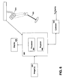
- Fig. 2 shows a patient P lying on a treatment couch 205 (or other patient-support assembly) of a linear accelerator 210, in an initial position.
- This initial position may be arbitrary, or the patient may have markings (such as tattoos or ink marks) that are aligned to a room coordinate system, which in some cases may be defined by a set of perpendicular lasers.
- the wand tool 200 is tracked by a tracker 215 attached to the ceiling 220 of the treatment room.
- the tracker may be attached to another fixed and known position in the room, such as a wall, beam and/or fixture.
- the tracker can also be mobile if there is a fixed object or tool that can be used to define a patient coordinate system.
- the output of the tracker 215 is transmitted (using wired or wireless methods) to a computer 225 having an associated visual display 230.
- the computer 225 processes the output to derive the orientation of the wand axis and the position of the wand tip in the room coordinate system.
- the computer 225 may in some instances be integrated directly into the console of the visual display 230, or can be located outside the treatment room, connected to or communicating wirelessly with the display 230.
- the visual display 230 can be cart-based but is preferably mounted to a swing arm 235 attached to the ceiling, such that the user (e.g., a radiation therapist, a dosimetrist, a medical physicist or a radiation oncologist) can move the visual display 230 to any convenient location.
- a radiation therapist e.g., a radiation therapist, a dosimetrist, a medical physicist or a radiation oncologist
- the physician may use a marking tool to draw a closed shape on the patient's skin, typically surrounding the patient's scar, which corresponds to the desired treatment aperture.
- the user then digitizes this shape by tracing the tip of the wand tool around the contour.
- the computer 225 acquires the traced shape via the tracking system 215 as a discrete set of points with known locations in the room coordinate system.
- another pointer tool or digitizing device such as a camera can be used to digitize the points represented by the drawn shape, but using the wand tool directly is more convenient than using two separate tools.
- the computer 225 captures the position and orientation of the wand (e.g., in response to pressing a button on the touch screen 230 or on the wand itself indicating that the user is satisfied with the wand position, or in response to a stability criterion indicating the user has stopped moving the wand).
- the tip of the wand corresponds to the desired beam entry point, and the orientation of the wand defines the beam direction.
- the computer calculates the couch shifts required to align the patient to the beam entry point to a defined SSD, and the couch and gantry rotations required so that the direction of treatment beam will follow the captured wand orientation.
- An SSD of 100 cm is usually used for electron boost treatments.
- the computer may be programmed to recognize wand orientations that correspond to impossible gantry and couch movements, and to cause a warning to be displayed on the screen 230 in such cases.
- the necessary movements are executed as shown in Fig. 3 .
- this is done by transferring the couch and gantry parameters directly to the computer driving the couch and LINAC.
- the user moves the gantry and couch manually.
- the manual couch motion can be simplified by mounting an attachment 300 to the couch which has active or passive markers affixed to it.
- the camera 315 tracks the motion and feeds this information back to the computer 225, which is programmed to assist the user -e.g., indicating how much to move and rotate the couch until the correct parameters are achieved.
- the beam entry point may be digitized with the pointer tip separately from the beam orientation.
- the beam direction may be determined by other means, and only the beam entry point, along with associated calculated couch shifts, is determined with the wand.
- the beam entry point with the wand instead of digitizing the beam entry point with the wand, it is calculated from digital surface data obtained from the patient.
- surface information can be acquired by sampling multiple points on the patient's surface with the wand tip, or by using a three-dimensional surface camera. If an image (such as a CT) of the patient is acquired which encompasses the patient's skin, the surface information can be extracted from the image for this purpose using manual or automatic contouring algorithms.
- the digitized cut-out information may be printed to enable correct machining of the treatment field aperture, often referred to as an electron cut-out.
- the digitized cut-out may also be sent electronically to a milling machine, which creates the cut-out.
- the electron applicator 320 may be affixed to the LINAC. If the cut-out exists in the clinic, which will usually be the case if it is simple such as a standard square or circle, it can be affixed to the applicator and the treatment delivered; otherwise, treatment will usually be delayed to a succeeding treatment session.
- the wand tip or other digitizing tool may also (or alternatively) be used to digitize anatomic surface structures (such as scar and areola) directly, while the patient P is in the initial position.
- the user interface 400 can then display the digitized information in the beam's-eye view 405 of the wand as it is moved about the patient, allowing the user to determine beam entry position and/or beam angle directly on the user interface.
- the cut-out can then be defined directly on the screen as well.
- one or more images are acquired with the patient P in the initial position.
- a three-dimensional ultrasound, a cone-beam CT image, MRI, or multiple two-dimensional x-ray projection images can be obtained.
- Anatomical information such as the lumpectomy cavity and chest wall, can then be segmented from these images manually or using conventional algorithms.
- the projection of the extracted surfaces 410 can then be displayed in real-time on the visual display 400 along the beam's-eye view defined by the wand. This allows the beam entry point and beam direction, as well as the cut-out shape, to be determined based on both external and internal anatomical features.
- Fig. 4 shows one embodiment where the cut-out drawn on the skin 415 is digitized and shown as 420 on the visual display 400 within the beam's-eye view 405.
- the contour of the scar 425 is also digitized and shown as a projection 430 along the beam's-eye view.
- the internal anatomy of interest 435 is segmented and its projection 410 is shown in the beam's-eye view.
- the areola 440 may also be digitized and included in the beam's-eye view.
- the tip of the wand 445 is positioned such that it corresponds to the beam entry point, and hence the center of the beam's-eye view 450.
- the wand orientation and beam alignment corresponding to the current gantry angle and couch position are updated in the visual display.
- the computed couch positions may be updated as the wand is moved to indicate which displacements will result in correct alignment of the patient such that the digitized beam entry point is at the correct SSD.
- the invention can be used for subsequent treatment fractions as well as the initial treatment or simulation.
- the cut-out is already known from the first treatment session or simulation, but adjustments must ordinarily be made in the beam angle and position to compensate for daily changes in patient setup, and deformations of the anatomy to be treated.
- the planned cut-out may be superimposed (as shown at 420) on the projection of internal and external anatomical information in the beam's-eye view as the wand is moved about the patient.
- the user can employ the wand to define the beam entry point relative to internal and/or external anatomy, and the real-time beam's-eye view is fixed at the planned couch and gantry values. If the user is not able to determine an appropriate setup based on beam entry point alone, the wand can be used to determine daily couch and gantry angles as well. In this regard, it may be useful to display not only the current internal and external anatomy relative to the wand, but the anatomy at time of planning as well.
- the amount of movement required for alignment can be done, for example, by comparing the location of the contoured target area at time of treatment to the location of the same area at time of planning in order to calculate a virtual target shift.
- the position can also be calculated from the beam aperture information.
- the beam entry point at the required SSD should also be taken into account, however. This may be done, for example, by guiding the user to digitize the beam entry point corresponding to the virtual target shift on the patient's skin. As shown in Fig.
- this guidance procedure can involve displaying the real-time position of the wand tip 500 in a beam's-eye view 505 relative to the central axis (i.e., the intersection of x and y axes 510, 515).
- the user then moves the pointer tip such that its position 500 corresponds to the central axis within a set tolerance 520.
- the patient shift identified on the screen 525 may then converted into physical couch shifts required to align the patient to the beam, and the shifts are actually carried out (either automatically, manually, or in some cases a combination of both) with the patient on the couch.
- a system for establishing radiation beam parameters for treatment of a patient includes the wand tool 100 and the tracking device 215 describe above, and a processor 600.
- the processor performs the calculations necessary to characterize the preferred beam trajectory and beam entry point based on tracking data received from the tracking device 215 as it follows the tool 100 about the patient.
- the processor may implement and execute the functionality described above using stored computer programming instructions, hardware components, or a combination of both.
- the parameters generated by the processor are provided to a controller 620, which causes a gantry and/or a gantry couch to move, thus properly aligning the beam and the patient according to the preferred beam angle, entry point and SSD.
- image data related to the location and orientation of the tool 100 may be augmented with imaging data representative of internal and/or external anatomical features of the patient.
- one or more imagers 630 may be used (e.g., MRI, CT, X-Ray, digital photography, etc.) to capture the images.
- the image data may then the transferred to and/or stored on a register 640 for subsequent use and display on one or more display devices 650.
- the processor 600 and register 630 may implement the functionality of the present invention in hardware or software, or a combination of both on a general-purpose or special-purpose computer 600.
- a program may set aside portions of a computer's random access memory to provide control logic that affects one or more of the tool tracking, image manipulation, image fusion, display, and gantry control.
- the program may be written in any one of a number of high-level languages, such as FORTRAN, PASCAL, C, C++, C#, Java, Tcl, or BASIC. Further, the program can be written in a script, macro, or functionality embedded in commercially available software, such as EXCEL or VISUAL BASIC.
- the software could be implemented in an assembly language directed to a microprocessor resident on a computer.
- the software can be implemented in Intel 80x86 assembly language if it is configured to run on an IBM PC or PC clone.
- the software may be embedded on an article of manufacture including, but not limited to, "computer-readable program means" such as a floppy disk, a hard disk, an optical disk, a magnetic tape, a PROM, an EPROM, or CD-ROM.
Description
- This invention relates generally to methods and systems for improving setups in radiotherapy.
- External-beam radiotherapy for breast cancer is typically provided using opposing tangential fields, which deliver a uniform dose to the entire affected breast. The primary treatment is given over a number of sessions, and is often followed by additional boost sessions. The boost sessions are typically delivered with an electron beam, which limits treatment to the primary lumpectomy site.
- Unlike photons, the intensities of which decrease exponentially as the photons travel through a patient, an electron beam deposits most of its energy dose within a fixed, finite range based primarily on the energy of the beam. Thus, a single electron beam can be used to treat superficial lesions while sparing underlying healthy tissues. Electron-beam treatments are typically delivered using electron cones of various sizes and shapes that may be attached to the collimator of a linear accelerator (LINAC), and which collimate the electron beam very close to the patient surface. The cones may have standard geometric shapes, such as circles or squares of various sizes, or an arbitrary shape can be custom-made for a given patient. In some instances, a lead sheet having an opening that defines the aperture of the beam is placed directly on the patient's skin.
- Electron-beam treatment plans usually involve a fixed source-to-skin distance (SSD). For breast boosts, an SSD of 100 cm is typical, as this is the same distance from the beam source to the isocenter of most LINACS. As a result, the LINAC isocenter, and hence the intersection of any wall lasers being used to align the patient with the LINAC, lies on the surface of the patient's skin. This is in contrast to many photon treatments, which are planned such that the isocenter is near the center of the treatment volume within the patient, as opposed to on the patient's skin.
- For a breast boost, the electron field ideally covers the tumor bed and the surgical path leading from the tumor bed to the surgical scar, plus a 1-2 cm margin. In addition, it is preferable to avoid the areola. Electron breast boosts may be simulated either using clinical or CT planning performed directly on the linear accelerator, or on a conventional simulator. In such simulations, a physician uses the lumpectomy scar and palpation to determine the location of the lumpectomy site relative to the patient's skin. A cut-out, usually made of CERROBEND, is designed to cover the region of interest on the patient's skin. The angles of the beam gantry and the couch on which the patient reclines are physically adjusted such that the beam is substantially perpendicular to (i.e., en face) the patient's skin. The appropriate electron energy is then chosen so that the beam covers the depth of the tumor bed, which may be found from post-surgery ultrasound scans, for example. The greater the energy of the electron beam, the deeper the electrons will penetrate. The correct number of "Monitor Units," a calibrated measure of LINAC output, required to deliver a percentage of the prescribed dose at a given depth is calculated from tabulated beam data.
- One weakness of clinical planning is that the actual position of the cavity is not explicitly taken into account. For this reason, in some institutions the simulation is performed using computed tomography (CT-SIM). One such technique uses radio-opaque wire placed around the surgical scar, and sometimes around the areola, prior to the acquisition of a CT scan. Thus the scar and the lumpectomy site, as seen on the CT scan, can be used to design the electron field. Energy and monitor units are calculated using treatment-planning software.
- Once the plan (clinical or CT-based) is finished, the goal is to deliver radiation treatment according to the plan for each treatment session, or fraction thereof. For each fraction, the setup may be adjusted so that the field covers the same skin surface area as planned, using a preferred source-to-skin distance (SSD), with the beam oriented en face. These adjustments are often necessary because it is difficult to reposition the breast in exactly the same way from day to day since the breast is not a rigid structure, and consequently its shape, size and position can vary daily. Therefore, the setup can be adjusted by changing couch position, collimator angle, gantry angle and/or couch angle to take into account external features.
- In making adjustements, it is possible to take into account not only external landmarks, but also internal anatomy. Physically moving and/or rotating the couch, gantry and collimator to properly orient the patient can be cumbersome, however, primarily due to the constraint of maintaining the planned SSD. Therefore, greater automation would be beneficial in utilizing internal and/or external landmark information to adjust patient setup, particularly where the planned SSD is taken into account.
-
US 2006/0285641 A1 (Scherch ) relates to a system, tracker, and program product to facilitate and verify proper target alignment for radiation delivery, and related methods. The system includes a trackable body having a trackable body reference point to be positioned adjacent a surface point of a patient to determine a position of such surface point. -
US 2008/0064953 A1 (Falco ) describes a system for displaying a projection of the patient's internal anatomy from the perspective of a linac beam. - According to the present invention there is provided a method for establishing radiation beam parameters for delivery of radiotherapy treatment to a patient using a radiotherapy treatment device as defined in claim 1 below. According to the present invention there is further provided a system for establishing radiation beam parameters for treatment of a patient as defined in claim 13 below.
- Embodiments of the present invention provide systems and methods for incorporating internal and external anatomical features of a patient and radiation-beam parameters into radiation-treatment treatment and/or planning regimens. A tracked tool or instrument may be used to illustrate a desired beam entry point and/or beam angle, which in turn facilitates the determination of the desired gantry and couch angles as well as couch positions. An SSD may also be determined and, in some cases, enforced prior to or during treatment.
- In a first aspect, various embodiments of the invention provide methods for establishing radiation beam parameters for delivery of radiotherapy treatment to a patient using a radiotherapy treatment device. The method includes the steps of orienting a wand with respect to the patient to establish a beam entry point and acquiring positional parameters characterising the wand's position (such as a tip position and/or an orientation) with respect to a room coordinate system. A beam angle is defined according to the room coordinate system that is consistent with the beam entry point.
- According to the invention images of internal anatomical features of the patient are obtained (using, for example, CT scanning, MRI, and/or ultrasound devices) and/or external anatomical features of the patient are digitized as images. The patient's internal and/or external anatomy is then displayed within the beam area corresponding to the defined beam angle such that the anatomical features are viewed along with the desired entry point and treatment path.
- In some embodiments, the tool is a wand-like instrument having a shaft and a well-defined tip, and one or more affixed markers that can be tracked by a tracking device. This tracking device, through known calibration techniques, can determine the position of the tip, as well as the orientation of the wand, in a "room coordinate system" of a planning room or a treatment room. The positions and orientations of the wand are preferably output to a computer application, with an interactive display in the room.
- The orientation of the wand is used to define a beam angle - that is, the user orients the wand relative to the patient's external anatomy to establish a desired beam trajectory relative to the patient. In practice, this hypothetical angle can be converted to gantry and couch angles of a LINAC by a computer application so that the actual beam angle during treatment conforms to the hypothetical angle established using the wand.
- In some embodiments, the wand tip is used to digitize a hypothetical beam entry point on the patient's surface. This is particularly useful for fixed SSD beam setups, where a given point on the patient's skin must be set up at a predetermined distance from the radiation source. The beam entry point can be converted to physical manipulations - e.g., translations and/or rotations of the couch, gantry and/or collimator - required to set up the patient to the digitized beam entry point, so the actual beam entry point corresponds to the hypothetical point established using the wand. In this way, physical geometry of the patient setup matches the geometry defined by the wand tool. The necessary physical manipulations can be performed automatically by transferring parameters specifying the movements to electromechanical controllers, or manually by providing these parameters as movement instructions that the therapist may carry out. Couch motion and/or rotation can also be facilitated by affixing trackable markers to the treatment couch, and tracking these markers while the couch is moved. A computer program tracking the markers can guide the therapist as physical manipulations are carried out so that the correct position and angle are attained. In some cases, the planned couch and gantry angles may not be optimal on a given day due, for example, to varying patient anatomy or setup position. For example, in breast setups, the size, shape and position of the breast and its internal targeted structures can vary from day to day. In these cases, the wand can be used to calculate new gantry and couch angles for the patient. In some cases this is done in combination with the determination of the beam entry point.
- The beam entry point may be calculated automatically from surface information. For example, surface information can be acquired by sampling multiple points on the patient's body surface with the wand tip, or by using a three-dimensional surface camera. Alternatively, surface data can be extracted from a patient image.
- In another aspect, embodiments of the invention provide a system for establishing radiation beam parameters for treatment of a patient. The system includes a tool and a tracking device for sensing positional information of the tool (e.g., tip position, orientation) with respect to the patient and to establish a beam entry point. The system also includes a processor for characterizing a beam trajectory through the beam entry point with respect to a room coordinate system and defining a desired beam angle consistent with the beam entry point.
- In some embodiments, the tool further comprises one or more optical tracking sensors identified by the tool tracking device, which may use optical and/or radio-frequency modalities (as well as others) to locate and track the tool as it is manipulated about the patient. The system may includes one or more registers for storing image data corresponding to internal and/or external anatomical features of the patient, and in some implementations the imaging devices for obtaining the image data. In some cases, some images may be obtained by tracing external anatomical features using the tool. The system may also include a display device for displaying the internal and/or external anatomical features of the patient within a beam's eye view of a radiation treatment device, wherein the beam's eye view is oriented along the desired beam angle. The display may also provide additional beam information, such as a beam aperture, a dose information, and an electron beam depth.
- A controller may be used to determine couch and/or gantry movement parameters, and direct the movement of either such that a radiation beam may be delivered to the patient along the desired beam angle. In certain cases, the processor correlates the beam entry point with a desired source-to-skin distance. In such instances, the tool orientation may also define a current source-to-skin distance, and the controller may further determine couch and/or gantry movement parameters for shifting the current source-to-skin distance to a desired source-to-skin distance.
- The foregoing and other objects, features, and advantages of the present invention, as well as the invention itself, will be more fully understood from the following description of various embodiments, when read together with the accompanying drawings, in which:
-
Figs. 1(a) - 1(c) illustrate a wand tool which may be used to guide radiation beams in accordance with various embodiments of the invention; -
Fig. 2 illustrates the administration of radiation therapy in accordance with various embodiments of the invention; -
Fig. 3 illustrates adjustments being made to the orientation of a radiation delivery system in accordance with various embodiments of the invention; -
Fig. 4 illustrates a treatment being delivered to a patient and a corresponding display of the treatment in accordance with various embodiments of the invention; -
Fig. 5 illustrates the a guidance procedure used to calibrate the delivery of radiotherapy to a patient in accordance with various embodiments of the invention; and -
Fig. 6 schematically depicts a system for orienting a patient in preparation for delivery of radiotherapy treatment in accordance with various embodiments of the invention. -
Fig. 1 illustrates an exemplary wand tool in accordance with various embodiments of the invention. As shown inFig. 1 (a) , the wand has ashaft 100 and atip 105 that is preferably well-defined, for example, as a sharp, blunt or ball tip. In some embodiments, an array ofmarkers 110 are affixed to the pointer. Themarkers 110 can be detected by a conventional optical tracker in real-time. The markers can be tracked either individually or as a preconfigured shape configuration, which defines a position and orientation in space. The position and orientation are calibrated so that the position of thetip 105, the orientation of theshaft 100, long-axis rotation and shaft rotation about its long axis, can be calculated at any given time as the wand is moved. Examples of markers include passive infrared reflectors, or active infrared emitters, which can be tracked by an optical camera or cameras such as the POLARIS family of cameras. Other types of trackers, such as magnetic or radio-frequency devices, can also be used. -
Fig. 1 (b) shows the addition of aplate 115, which is preferably transparent to allow the user to more easily judge whether or not a surface is perpendicular to the wand tool (i.e., whether it is en face to the skin surface). Theplate 115 may be removable so that the wand tool can be more easily used for other functions where the user needs a clear view of thetip 105, such as digitizing points on a surface. In some cases, the distance between theplate 115 and thetip 105 can correspond to a physical distance related to the radiation device, such as the distance between the applicator and the skin. In another variation, shown inFig. 1 (c) , a plate 120 (illustrated with a circular shape) is affixed at the end of therod 100. Theplate 120 can make evaluating en face angles easier, but at the expense of losing precise awareness of the position of thetip 105. Thisplate 120 may also be removable, or adjustable up and down the shaft. - Calibration of the wand tool with respect to the room coordinate system may be more accurate when the mechanical geometry of the markers is known relative to the axis of the tool and its tip, e.g., from a precise CAD geometry. The relationship between the tool axis and tip to the pattern recorded by the tracker can then be calculated. If the geometry is not known accurately enough, or if there is too much variability in manufacturing the tool, appropriate calibration can be performed using other methods known in the art. For example, a snapshot of the markers can be acquired with the tracker to establish the marker pattern. Mechanical rotations of the tool about the tip, along pre-established trajectories, during marker acquisition by the tracker can then be used to mathematically extract the transformation between the tip and the marker pattern. Similar established motions along or about the axis of the tool can also be used to define the transformation between the axis and the pattern. Once calibration is complete, the tip position and wand orientation can be converted to room coordinates as is commonly done in the art.
- In some embodiments, aspects of the beam defined by the wand are used for treatment planning purposes. The beam or beams are defined with the patient present, using the wand, and, in some cases, taking into account external and/or internal features. This beam definition is sent to a treatment planning computer, or in some cases to an in-room computer associated with the LINAC, to determine proper patient positioning and/or to calculate dose distributions. Having the patient present for design of treatment beams, rather than designing them exclusively on pre-acquired images, can be of particular importance for clinical setups, where the physician may want to take visible and/or palpable information into account in the beam design. The ability to design a beam directly on the patients' skin, for planning or treatment purposes, is especially useful for electron beams which are generally kept en face. The beam can be designed to target the appropriate structures while ensuring visually that it is en face.
- One exemplary application of the techniques described herein involves clinical planning of a breast electron boost beam, which is typically carried out directly on a LINAC or on a conventional simulator. Critical treatment parameters include the beam angle (defined by a gantry and couch rotation) and beam entry point required to target the visible external information, each determined while maintaining an en face beam direction and a fixed source-to-skin distance (SSD) (together referred to as "beam alignment"). Internal image information may also be considered when determining beam alignment. Other information which can be obtained is beam depth and energy, collimator rotation and an electron cut-out shape.
- Typically, the user orients the wand relative to the patient's skin. For example, the user may align the axis of the wand so that it is en face. In certain embodiments, an image of the patient is acquired prior to use of the wand and used as a guide. As the user moves the wand about the patient, the tracked wand coordinates - relative to the patient or room coordinate system - are keyed to the coordinates of internal images of the patient's anatomy, so that elements of the internal anatomy (e.g., a lesion, tumor bed or cavity) are displayed and updated as the position and orientation of the wand changes. The internal images may have been obtained during the same planning or treatment session using, for example, CT scanning, cone-beam CT, MRI, and/or ultrasound devices.
- In some embodiments, turning the wand about its axis simulates a collimator rotation, which is calculated along with the couch and gantry parameters. In other embodiments, the collimator may be rotated on-screen after the gantry and couch angles have been calculated using the wand. Once the wand position is aligned according to a desired beam trajectory relative to the patient's anatomy, the position of the patient may be adjusted such that the actual treatment device beam (which, in some cases may be fixed) corresponds to the desired beam trajectory.
- In other embodiments, the system may be used to define a beam digitally for future dosimetric or geometric planning purposes. This can be done, for example, in a CT-SIM room, a conventional simulator, or on the LINAC. The orientation of the wand used to define the beam can then be converted to beam orientation and/or couch and gantry angles, and sent electronically to a treatment planning system, e.g., via the DICOM transfer protocol. This approach, which effectively combines elements of both CT planning and clinical planning, is of particular use in the CT-SIM room, where it can be difficult to visualize different beam orientations directly on the patient.
- In practice, the internal anatomy is displayed on an interactive monitor in either the "beam's-eye view" or in a plane perpendicular to or passing through the axis of the beam (i.e., along the depth direction). In addition to or instead of displaying actual image gray-scale information, surfaces or contours of external anatomical landmarks (e.g., scars, markings, etc.) can be displayed relative to the wand. Where external points or contours of interest on the patient's skin are digitized, the tip of the wand may be used to identify or outline the contours, which are then simultaneously displayed on the interactive monitor along with the internal features.
- In some embodiments, the interactive display updates a beam's-eye-view plane perpendicular to the wand's direction, along with the treatment aperture of the radiation beam. This facilitates visualization of which internal and external structures fall within the radiation beam. The depth direction may be shown separately or in combination with the beam's-eye view. This is particularly useful for electron treatments, where the depth of the electron beam can be displayed to ensure proper coverage of the involved anatomy. Dosimetric information can be displayed relative to the anatomy as well, in any view.
- In some embodiments in which the radiation treatment is delivered in multiple fractions, the process is divided into two steps. In the first step, the cavity position identified in the pre-treatment image is aligned (manually or automatically) to its position at treatment time by conventional image-alignment software and displayed to the user. In the second step, the user employs the wand tip to digitize the beam entry point (corresponding to the beam central axis on the patient's skin) with the image of the cavity. This can be done by displaying the real-time position of the wand tip on the display relative to the virtual beam's-eye view (i.e., the beam view relative to the virtual cavity alignment). The user then moves the wand such that its tip lies on the patient's skin surface and within a specified tolerance from the central axis of the beam's-eye view on the display. The patient shifts required to align the patient to the beam can then be calculated from the cavity shift and beam entry point. Using the example above in which a breast electron boost beam is delivered using a LINAC having a fixed beam, the position of the patient may be moved by adjusting the physical alignment of a couch relative to the LINAC using multiple (e.g., typically three or as many as six) degrees of freedom.
-
Fig. 2 shows a patient P lying on a treatment couch 205 (or other patient-support assembly) of alinear accelerator 210, in an initial position. This initial position may be arbitrary, or the patient may have markings (such as tattoos or ink marks) that are aligned to a room coordinate system, which in some cases may be defined by a set of perpendicular lasers. Thewand tool 200 is tracked by atracker 215 attached to the ceiling 220 of the treatment room. Alternatively, the tracker may be attached to another fixed and known position in the room, such as a wall, beam and/or fixture. The tracker can also be mobile if there is a fixed object or tool that can be used to define a patient coordinate system. The output of thetracker 215 is transmitted (using wired or wireless methods) to acomputer 225 having an associatedvisual display 230. Using suitable calibration data, thecomputer 225 processes the output to derive the orientation of the wand axis and the position of the wand tip in the room coordinate system. Thecomputer 225 may in some instances be integrated directly into the console of thevisual display 230, or can be located outside the treatment room, connected to or communicating wirelessly with thedisplay 230. Thevisual display 230 can be cart-based but is preferably mounted to aswing arm 235 attached to the ceiling, such that the user (e.g., a radiation therapist, a dosimetrist, a medical physicist or a radiation oncologist) can move thevisual display 230 to any convenient location. - In some embodiments; the physician may use a marking tool to draw a closed shape on the patient's skin, typically surrounding the patient's scar, which corresponds to the desired treatment aperture. The user then digitizes this shape by tracing the tip of the wand tool around the contour. The
computer 225 acquires the traced shape via thetracking system 215 as a discrete set of points with known locations in the room coordinate system. Alternatively, another pointer tool or digitizing device such as a camera can be used to digitize the points represented by the drawn shape, but using the wand tool directly is more convenient than using two separate tools. - The user then moves the wand tool such that the tip is at the desired entry point of the beam on the patient's surface, typically close to the center of the drawn aperture, and ensures that its axis is en face to the patient's skin. Once the user establishes the proper position and orientation of the wand tool relative to the patient, the
computer 225 captures the position and orientation of the wand (e.g., in response to pressing a button on thetouch screen 230 or on the wand itself indicating that the user is satisfied with the wand position, or in response to a stability criterion indicating the user has stopped moving the wand). The tip of the wand corresponds to the desired beam entry point, and the orientation of the wand defines the beam direction. Based on the mechanical movement constraints and capabilities of the couch and the gantry, which are programmed into thecomputer 225, the computer calculates the couch shifts required to align the patient to the beam entry point to a defined SSD, and the couch and gantry rotations required so that the direction of treatment beam will follow the captured wand orientation. An SSD of 100 cm is usually used for electron boost treatments. The computer may be programmed to recognize wand orientations that correspond to impossible gantry and couch movements, and to cause a warning to be displayed on thescreen 230 in such cases. - Assuming the beam direction established by the wand position and orientation can be accommodated by the couch and gantry, the necessary movements are executed as shown in
Fig. 3 . In some embodiments, this is done by transferring the couch and gantry parameters directly to the computer driving the couch and LINAC. In other embodiments, the user moves the gantry and couch manually. The manual couch motion can be simplified by mounting anattachment 300 to the couch which has active or passive markers affixed to it. As the user moves and/or rotates the couch, thecamera 315 tracks the motion and feeds this information back to thecomputer 225, which is programmed to assist the user -e.g., indicating how much to move and rotate the couch until the correct parameters are achieved. - For ease of use, the beam entry point may be digitized with the pointer tip separately from the beam orientation. In other embodiments, the beam direction may be determined by other means, and only the beam entry point, along with associated calculated couch shifts, is determined with the wand.
- In alternative embodiments, instead of digitizing the beam entry point with the wand, it is calculated from digital surface data obtained from the patient. For example, surface information can be acquired by sampling multiple points on the patient's surface with the wand tip, or by using a three-dimensional surface camera. If an image (such as a CT) of the patient is acquired which encompasses the patient's skin, the surface information can be extracted from the image for this purpose using manual or automatic contouring algorithms.
- If desired, the digitized cut-out information may be printed to enable correct machining of the treatment field aperture, often referred to as an electron cut-out. The digitized cut-out may also be sent electronically to a milling machine, which creates the cut-out. At any time, the
electron applicator 320 may be affixed to the LINAC. If the cut-out exists in the clinic, which will usually be the case if it is simple such as a standard square or circle, it can be affixed to the applicator and the treatment delivered; otherwise, treatment will usually be delayed to a succeeding treatment session. - In addition to directly digitizing the aperture from markings drawn on the patient's skin, the wand tip or other digitizing tool may also (or alternatively) be used to digitize anatomic surface structures (such as scar and areola) directly, while the patient P is in the initial position. As shown in
Fig. 4 , theuser interface 400 can then display the digitized information in the beam's-eye view 405 of the wand as it is moved about the patient, allowing the user to determine beam entry position and/or beam angle directly on the user interface. The cut-out can then be defined directly on the screen as well. - Typically, one or more images are acquired with the patient P in the initial position. For example, a three-dimensional ultrasound, a cone-beam CT image, MRI, or multiple two-dimensional x-ray projection images can be obtained. Anatomical information, such as the lumpectomy cavity and chest wall, can then be segmented from these images manually or using conventional algorithms. The projection of the extracted
surfaces 410 can then be displayed in real-time on thevisual display 400 along the beam's-eye view defined by the wand. This allows the beam entry point and beam direction, as well as the cut-out shape, to be determined based on both external and internal anatomical features. -
Fig. 4 shows one embodiment where the cut-out drawn on theskin 415 is digitized and shown as 420 on thevisual display 400 within the beam's-eye view 405. The contour of thescar 425 is also digitized and shown as aprojection 430 along the beam's-eye view. The internal anatomy ofinterest 435 is segmented and itsprojection 410 is shown in the beam's-eye view. For breast treatments, theareola 440 may also be digitized and included in the beam's-eye view. The tip of thewand 445 is positioned such that it corresponds to the beam entry point, and hence the center of the beam's-eye view 450. The wand orientation and beam alignment corresponding to the current gantry angle and couch position are updated in the visual display. The computed couch positions may be updated as the wand is moved to indicate which displacements will result in correct alignment of the patient such that the digitized beam entry point is at the correct SSD. - The invention can be used for subsequent treatment fractions as well as the initial treatment or simulation. In this case the cut-out is already known from the first treatment session or simulation, but adjustments must ordinarily be made in the beam angle and position to compensate for daily changes in patient setup, and deformations of the anatomy to be treated. In this case, the planned cut-out may be superimposed (as shown at 420) on the projection of internal and external anatomical information in the beam's-eye view as the wand is moved about the patient.
- In some embodiments related to treatment fractions, it may be more practical to avoid adjusting the couch and gantry angles for each treatment fraction, and instead realign the beam relative to the patient anatomy using only couch displacements. In this case, the user can employ the wand to define the beam entry point relative to internal and/or external anatomy, and the real-time beam's-eye view is fixed at the planned couch and gantry values. If the user is not able to determine an appropriate setup based on beam entry point alone, the wand can be used to determine daily couch and gantry angles as well. In this regard, it may be useful to display not only the current internal and external anatomy relative to the wand, but the anatomy at time of planning as well.
- In other embodiments related to treatment fractions, it is more practical to first calculate the amount of movement required for alignment. This can be done, for example, by comparing the location of the contoured target area at time of treatment to the location of the same area at time of planning in order to calculate a virtual target shift. The position can also be calculated from the beam aperture information. The beam entry point at the required SSD should also be taken into account, however. This may be done, for example, by guiding the user to digitize the beam entry point corresponding to the virtual target shift on the patient's skin. As shown in
Fig. 5 , this guidance procedure can involve displaying the real-time position of thewand tip 500 in a beam's-eye view 505 relative to the central axis (i.e., the intersection of x andy axes 510, 515). The user then moves the pointer tip such that itsposition 500 corresponds to the central axis within aset tolerance 520. In order to help orient the user, it is useful to show a schematic model of the patient orientation on thedisplay screen 525. The patient shift identified on thescreen 525 that consider both cavity position and beam entry point, may then converted into physical couch shifts required to align the patient to the beam, and the shifts are actually carried out (either automatically, manually, or in some cases a combination of both) with the patient on the couch. - Referring to
Fig. 6 , a system for establishing radiation beam parameters for treatment of a patient includes thewand tool 100 and thetracking device 215 describe above, and aprocessor 600. The processor performs the calculations necessary to characterize the preferred beam trajectory and beam entry point based on tracking data received from thetracking device 215 as it follows thetool 100 about the patient. The processor may implement and execute the functionality described above using stored computer programming instructions, hardware components, or a combination of both. In some implementations, the parameters generated by the processor are provided to acontroller 620, which causes a gantry and/or a gantry couch to move, thus properly aligning the beam and the patient according to the preferred beam angle, entry point and SSD. - As described above, image data related to the location and orientation of the
tool 100 may be augmented with imaging data representative of internal and/or external anatomical features of the patient. In such cases, one ormore imagers 630 may be used (e.g., MRI, CT, X-Ray, digital photography, etc.) to capture the images. The image data may then the transferred to and/or stored on aregister 640 for subsequent use and display on one ormore display devices 650. - In some embodiments, the
processor 600 and register 630 may implement the functionality of the present invention in hardware or software, or a combination of both on a general-purpose or special-purpose computer 600. In addition, such a program may set aside portions of a computer's random access memory to provide control logic that affects one or more of the tool tracking, image manipulation, image fusion, display, and gantry control. In such an embodiment, the program may be written in any one of a number of high-level languages, such as FORTRAN, PASCAL, C, C++, C#, Java, Tcl, or BASIC. Further, the program can be written in a script, macro, or functionality embedded in commercially available software, such as EXCEL or VISUAL BASIC. Additionally, the software could be implemented in an assembly language directed to a microprocessor resident on a computer. For example, the software can be implemented in Intel 80x86 assembly language if it is configured to run on an IBM PC or PC clone. The software may be embedded on an article of manufacture including, but not limited to, "computer-readable program means" such as a floppy disk, a hard disk, an optical disk, a magnetic tape, a PROM, an EPROM, or CD-ROM. - While the invention has been particularly shown and described with reference to specific embodiments, it should be understood by those skilled in the art that various changes in form and detail may be made therein without departing from the scope of the invention as defined by the appended claims. The scope of the invention is thus indicated by the appended claims and all changes which come within the meaning and range of equivalency of the claims are therefore intended to be embraced.
Claims (18)
- A method for establishing radiation beam parameters for delivery of radiotherapy treatment to a patient using a radiotherapy treatment device, the method comprising:a. orienting a wand (100/500) with respect to the patient to establish a beam entry point;b. acquiring positional parameters characterizing wand positioning with respect to a room coordinate system;c. defining, in the room coordinate system, a beam angle consistent with the beam entry point established by the wand (100/500), characterized by:d. obtaining one or more images of the patient's internal (435) and/or external (410) anatomy; ande. visually representing portions of the patient's internal and/or external anatomy within a beam area corresponding to the defined beam angle, wherein the visual representations of the patient's internal and/or external anatomy comprises digitized images of one or more internal and/or external anatomical features of the patient's anatomy according to a beam's eye view (405) of a radiation treatment device, wherein the beam's eye view is orientated along the defined beam angle.
- The method of claim 1 wherein wand positioning comprises a position of a tip (105, 500) of the wand.
- The method of claim 1 wherein wand positioning comprises an orientation of the wand.
- The method of claim 1 wherein orienting the wand further establishes a beam trajectory or a collimator rotation.
- The method of claim 1 further comprising the step of converting the beam angle to couch (205) and gantry movement parameters.
- The method of claim 5 further comprising moving a gantry couch in accordance with the parameters.
- The method of claim 6 wherein movement of the couch is tracked and feedback specifying conformance to the parameters is provided to a user.
- The method of claim 1 wherein the beam angle is established relative to a curvature of the patient.
- The method of claim 1 wherein the visual representation comprises image points on a plane defined relative to the beam angle.
- The method of claim 9 where the plane is defined by the beam's-eye view.
- The method of claim 9 where the plane is perpendicular to the beam's-eye view.
- The method of claim 1 further comprising visually displaying beam information, the beam information comprising at least one of beam aperture, dose information, or electron beam depth.
- The method of claim 1 wherein the wand orientation defines a current source-to-skin distance (SSD), and further comprising defining a desired source-to-skin distance and computing couch and gantry movement parameters for shifting the current source-to-skin distance to the desired source-to-skin distance.
- A system for establishing radiation beam parameters for treatment of a patient (P), the system comprising:a. a tool (100); andb. a tool tracking device (215) adapted to sense an orientation of the tool with respect to the patient (P) to establish at least a beam entry point;c) a processor (600) adapted to characterize the beam entry point with respect to a room coordinate system and define a beam angle consistent with the beam entry point established by the tool tracking device (215); characterized by:d. a register (640) for storing one or more images of patient's internal and/or external anatomy;
and in thate. the processor (600) is further adapted to create a visual representation of portions of the patient's internal and/or external anatomy within a beam area corresponding to the defined beam angle, wherein the visual representations of the patient's internal and/or external anatomy comprise digitized images of one or more internal and/or external anatomical features of the patient's anatomy according to a beam's eye view (405) of a radiation treatment device, wherein the beam's eye view is orientated along the defined beam angle. - The system of claim 14 further comprising a display device (650) for displaying the one or more of the internal and external anatomical features of the patient within the beam's eye view of a radiation treatment device.
- The system of claim 14 further comprising a controller (620) for determining couch and gantry movement parameters, and directing movement of at least one of the gantry and the couch such that a radiation beam may be delivered to the patient along the defined beam angle.
- The system of claim 16 wherein the processor correlates the beam entry point with a desired source-to-skin distance (SSD).
- The system of claim 17 wherein the tool orientation defines a current source-to-skin distance, the controller (620) computing couch and gantry movement parameters for shifting the current source-to-skin distance to the desired source-to-skin distance.
Applications Claiming Priority (2)
| Application Number | Priority Date | Filing Date | Title |
|---|---|---|---|
| US5804908P | 2008-06-02 | 2008-06-02 | |
| PCT/CA2009/000750 WO2009146532A1 (en) | 2008-06-02 | 2009-06-01 | Methods and systems for guiding radiotherapy setups |
Publications (3)
| Publication Number | Publication Date |
|---|---|
| EP2293843A1 EP2293843A1 (en) | 2011-03-16 |
| EP2293843A4 EP2293843A4 (en) | 2011-07-06 |
| EP2293843B1 true EP2293843B1 (en) | 2012-09-19 |
Family
ID=41397668
Family Applications (1)
| Application Number | Title | Priority Date | Filing Date |
|---|---|---|---|
| EP09756994A Active EP2293843B1 (en) | 2008-06-02 | 2009-06-01 | Methods and systems for guiding radiotherapy setups |
Country Status (5)
| Country | Link |
|---|---|
| US (1) | US8189738B2 (en) |
| EP (1) | EP2293843B1 (en) |
| CA (1) | CA2726668C (en) |
| ES (1) | ES2396029T3 (en) |
| WO (1) | WO2009146532A1 (en) |
Families Citing this family (41)
| Publication number | Priority date | Publication date | Assignee | Title |
|---|---|---|---|---|
| US7448734B2 (en) * | 2004-01-21 | 2008-11-11 | Silverbrook Research Pty Ltd | Inkjet printer cartridge with pagewidth printhead |
| US8983024B2 (en) | 2006-04-14 | 2015-03-17 | William Beaumont Hospital | Tetrahedron beam computed tomography with multiple detectors and/or source arrays |
| US9339243B2 (en) | 2006-04-14 | 2016-05-17 | William Beaumont Hospital | Image guided radiotherapy with dual source and dual detector arrays tetrahedron beam computed tomography |
| CN102218198A (en) * | 2006-05-25 | 2011-10-19 | 威廉博蒙特医院 | Method for forming a portal image |
| US8348846B2 (en) * | 2008-09-30 | 2013-01-08 | Mediri Gmbh | 3D motion detection and correction by object tracking in ultrasound images |
| US8670523B2 (en) | 2010-01-05 | 2014-03-11 | William Beaumont Hospital | Intensity modulated arc therapy with continuous couch rotation/shift and simultaneous cone beam imaging |
| US20110306863A1 (en) * | 2010-06-15 | 2011-12-15 | Jason Koshnitsky | Patient alignment system for diagnostic and therapeutic procedures |
| JP5492030B2 (en) * | 2010-08-31 | 2014-05-14 | 富士フイルム株式会社 | Image pickup display device and method of operating the same |
| US20130142310A1 (en) * | 2011-06-06 | 2013-06-06 | The Board Of Trustees Of The Leland Stanford Junior University | Dynamic multi-axes trajectory optimization and delivery method for radiation treatment |
| US10076296B2 (en) | 2011-11-14 | 2018-09-18 | Koninklijke Philips N.V. | User interface for X-ray positioning |
| US9561387B2 (en) | 2012-04-12 | 2017-02-07 | Unitversity of Florida Research Foundation, Inc. | Ambiguity-free optical tracking system |
| US20140123388A1 (en) * | 2012-11-05 | 2014-05-08 | Reto W. Filiberti | Automated initial setup positioning for speeding patient throughput |
| JP6662785B2 (en) | 2014-03-17 | 2020-03-11 | インテュイティブ サージカル オペレーションズ, インコーポレイテッド | System and method for re-centering an imaging device and input controls |
| US9950194B2 (en) | 2014-09-09 | 2018-04-24 | Mevion Medical Systems, Inc. | Patient positioning system |
| US10617891B2 (en) | 2015-04-23 | 2020-04-14 | Sun Nuclear Corporation | Radiation detector calibration |
| US10485992B2 (en) | 2015-06-19 | 2019-11-26 | Koninklijke Philips N.V. | Ultrasound guided radiotherapy system |
| EP3423154B1 (en) * | 2016-03-01 | 2021-05-05 | Intraop Medical Corporation | Low energy electron beam radiation system that generates electron beams with precisely controlled and adjustable penetration depth useful for therapeutic applications |
| WO2018023049A1 (en) * | 2016-07-28 | 2018-02-01 | Sun Nuclear Corporation | Beam angle direction determination |
| WO2018160763A1 (en) | 2017-02-28 | 2018-09-07 | Sun Nuclear Corporation | Radiation therapy treatment verification with electronic portal imaging device transit images |
| WO2019083886A1 (en) * | 2017-10-25 | 2019-05-02 | Intuitive Surgical Operations, Inc. | System and method for repositioning input control devices |
| US10426424B2 (en) | 2017-11-21 | 2019-10-01 | General Electric Company | System and method for generating and performing imaging protocol simulations |
| CN108273199A (en) * | 2018-01-19 | 2018-07-13 | 深圳市奥沃医学新技术发展有限公司 | A kind of method for detecting position, device and radiotherapy system |
| EP3826715A1 (en) | 2018-07-24 | 2021-06-02 | Brainlab AG | Beam path based patient positioning and monitoring |
| US11278744B2 (en) | 2018-09-28 | 2022-03-22 | Sun Nuclear Corporation | Systems and methods to account for tilt of a radiation measurement system |
| DE102018008806A1 (en) * | 2018-11-09 | 2020-05-14 | Städtisches Klinikum Dessau | Procedure for the authenticity-related correction of the spatial position of the central beam of radiation therapy devices and the patient position |
| WO2021007459A1 (en) | 2019-07-10 | 2021-01-14 | Sun Nuclear Corporation | Scintillator-based radiation therapy quality assurance |
| US11600004B2 (en) | 2019-07-10 | 2023-03-07 | Sun Nuclear Corporation | Image-based radiation therapy quality assurance |
| EP3996811A4 (en) * | 2019-07-11 | 2023-08-09 | The Trustees Of Dartmouth College | System and methods for optical imaging of dose deposited by therapeutic proton beams |
| US11786756B2 (en) | 2020-12-30 | 2023-10-17 | Varian Medical Systems, Inc. | Radiotherapy methods, systems, and workflow-oriented graphical user interfaces |
| US11577095B2 (en) | 2020-12-30 | 2023-02-14 | Varian Medical Systems, Inc. | Radiotherapy methods, systems, and workflow-oriented graphical user interfaces |
| US11638840B2 (en) * | 2020-12-30 | 2023-05-02 | Varian Medical Systems, Inc. | Radiotherapy methods, systems, and workflow-oriented graphical user interfaces |
| EP4271474A1 (en) * | 2020-12-30 | 2023-11-08 | Varian Medical Systems, Inc. | Radiotherapy methods, systems, and workflow-oriented graphical user interfaces |
| US11660473B2 (en) | 2020-12-30 | 2023-05-30 | Varian Medical Systems, Inc. | Radiotherapy methods, systems, and workflow-oriented graphical user interfaces |
| US11604564B2 (en) | 2020-12-30 | 2023-03-14 | Varian Medical Systems, Inc. | Radiotherapy methods, systems, and workflow-oriented graphical user interfaces |
| US11654303B2 (en) | 2020-12-30 | 2023-05-23 | Varian Medical Systems, Inc. | Radiotherapy methods, systems, and workflow-oriented graphical user interfaces |
| US11817210B2 (en) | 2020-12-30 | 2023-11-14 | Varian Medical Systems, Inc. | Radiotherapy methods, systems, and workflow-oriented graphical user interfaces |
| US11712587B2 (en) | 2020-12-30 | 2023-08-01 | Varian Medical Systems, Inc. | Radiotherapy methods, systems, and workflow-oriented graphical user interfaces |
| US11844962B2 (en) | 2020-12-30 | 2023-12-19 | Varian Medical Systems, Inc. | Radiotherapy methods, systems, and workflow-oriented graphical user interfaces |
| US11759656B2 (en) | 2020-12-30 | 2023-09-19 | Varian Medical Systems, Inc. | Radiotherapy methods, systems, and workflow-oriented graphical user interfaces |
| US11786757B2 (en) | 2020-12-30 | 2023-10-17 | Varian Medical Systems, Inc. | Radiotherapy methods, systems, and workflow-oriented graphical user interfaces |
| US11607563B2 (en) * | 2020-12-30 | 2023-03-21 | Varian Medical Systems, Inc. | Radiotherapy methods, systems, and workflow-oriented graphical user interfaces |
Family Cites Families (166)
| Publication number | Priority date | Publication date | Assignee | Title |
|---|---|---|---|---|
| US1006981A (en) | 1911-01-24 | 1911-10-24 | Theodore D Robinson | Lock-switch. |
| US3082322A (en) | 1958-11-28 | 1963-03-19 | Westinghouse Electric Corp | Therapy unit |
| US3991310A (en) | 1970-08-03 | 1976-11-09 | Morrison Richard A | Biplane radiographic localization of target center for radiotherapy |
| US3777124A (en) | 1970-11-27 | 1973-12-04 | Varian Associates | Computer assisted radiation therapy machine |
| US3987281A (en) | 1974-07-29 | 1976-10-19 | The United States Of America As Represented By The Department Of Health, Education And Welfare | Method of radiation therapy treatment planning |
| GB1572347A (en) | 1976-03-30 | 1980-07-30 | Emi Ltd | Radiographic apparatus |
| US4618978A (en) | 1983-10-21 | 1986-10-21 | Cosman Eric R | Means for localizing target coordinates in a body relative to a guidance system reference frame in any arbitrary plane as viewed by a tomographic image through the body |
| DE3844716C2 (en) | 1987-08-24 | 2001-02-22 | Mitsubishi Electric Corp | Ionised particle beam therapy device |
| JPS6472736A (en) | 1987-09-14 | 1989-03-17 | Toshiba Corp | Mri apparatus |
| GB2211709B (en) | 1987-10-28 | 1991-03-20 | Philips Electronic Associated | Multileaf collimator and related apparatus |
| US4991579A (en) | 1987-11-10 | 1991-02-12 | Allen George S | Method and apparatus for providing related images over time of a portion of the anatomy using fiducial implants |
| DE3852009D1 (en) | 1987-12-11 | 1994-12-08 | Varian International Ag | Therapy simulator. |
| FR2637189A1 (en) | 1988-10-04 | 1990-04-06 | Cgr Mev | SYSTEM AND METHOD FOR MEASURING AND / OR VERIFYING THE POSITION OF A PATIENT IN RADIOTHERAPY EQUIPMENT |
| US5099846A (en) | 1988-12-23 | 1992-03-31 | Hardy Tyrone L | Method and apparatus for video presentation from a variety of scanner imaging sources |
| US5117829A (en) | 1989-03-31 | 1992-06-02 | Loma Linda University Medical Center | Patient alignment system and procedure for radiation treatment |
| US5222499A (en) | 1989-11-15 | 1993-06-29 | Allen George S | Method and apparatus for imaging the anatomy |
| US5107839A (en) | 1990-05-04 | 1992-04-28 | Pavel V. Houdek | Computer controlled stereotaxic radiotherapy system and method |
| US5295483A (en) | 1990-05-11 | 1994-03-22 | Christopher Nowacki | Locating target in human body |
| US5086401A (en) | 1990-05-11 | 1992-02-04 | International Business Machines Corporation | Image-directed robotic system for precise robotic surgery including redundant consistency checking |
| US5138647A (en) | 1990-08-03 | 1992-08-11 | Siemens Medical Laboratories, Inc. | Portal imaging device |
| US5207223A (en) | 1990-10-19 | 1993-05-04 | Accuray, Inc. | Apparatus for and method of performing stereotaxic surgery |
| EP1690511B1 (en) | 1990-10-19 | 2010-07-14 | St. Louis University | Surgical probe locating system for head use |
| US6405072B1 (en) | 1991-01-28 | 2002-06-11 | Sherwood Services Ag | Apparatus and method for determining a location of an anatomical target with reference to a medical apparatus |
| US5291889A (en) | 1991-05-23 | 1994-03-08 | Vanguard Imaging Ltd. | Apparatus and method for spatially positioning images |
| US5734384A (en) | 1991-11-29 | 1998-03-31 | Picker International, Inc. | Cross-referenced sectioning and reprojection of diagnostic image volumes |
| US5233990A (en) | 1992-01-13 | 1993-08-10 | Gideon Barnea | Method and apparatus for diagnostic imaging in radiation therapy |
| US5715166A (en) | 1992-03-02 | 1998-02-03 | General Motors Corporation | Apparatus for the registration of three-dimensional shapes |
| US5317616A (en) | 1992-03-19 | 1994-05-31 | Wisconsin Alumni Research Foundation | Method and apparatus for radiation therapy |
| US5301674A (en) | 1992-03-27 | 1994-04-12 | Diasonics, Inc. | Method and apparatus for focusing transmission and reception of ultrasonic beams |
| US5389101A (en) | 1992-04-21 | 1995-02-14 | University Of Utah | Apparatus and method for photogrammetric surgical localization |
| US5603318A (en) | 1992-04-21 | 1997-02-18 | University Of Utah Research Foundation | Apparatus and method for photogrammetric surgical localization |
| US6122341A (en) | 1992-06-12 | 2000-09-19 | Butler; William E. | System for determining target positions in the body observed in CT image data |
| US5408101A (en) | 1992-07-06 | 1995-04-18 | Telaire Systems, Inc. | Laser assisted quasi-blackbody radiation source |
| FR2694881B1 (en) | 1992-07-31 | 1996-09-06 | Univ Joseph Fourier | METHOD FOR DETERMINING THE POSITION OF AN ORGAN. |
| US5391139A (en) | 1992-09-03 | 1995-02-21 | William Beaumont Hospital | Real time radiation treatment planning system |
| DE69431741T2 (en) | 1993-03-12 | 2003-09-11 | Toshiba Kawasaki Kk | Device for medical treatment with ultrasound |
| US5483961A (en) | 1993-03-19 | 1996-01-16 | Kelly; Patrick J. | Magnetic field digitizer for stereotactic surgery |
| US5379642A (en) | 1993-07-19 | 1995-01-10 | Diasonics Ultrasound, Inc. | Method and apparatus for performing imaging |
| US5446548A (en) | 1993-10-08 | 1995-08-29 | Siemens Medical Systems, Inc. | Patient positioning and monitoring system |
| US5411026A (en) | 1993-10-08 | 1995-05-02 | Nomos Corporation | Method and apparatus for lesion position verification |
| US5438991A (en) | 1993-10-18 | 1995-08-08 | William Beaumont Hospital | Method and apparatus for controlling a radiation treatment field |
| US5531227A (en) | 1994-01-28 | 1996-07-02 | Schneider Medical Technologies, Inc. | Imaging device and method |
| EP0673661B1 (en) | 1994-03-25 | 2003-03-12 | Kabushiki Kaisha Toshiba | Radiotherapy system |
| US20040015176A1 (en) | 1994-06-20 | 2004-01-22 | Cosman Eric R. | Stereotactic localizer system with dental impression |
| US5524627A (en) | 1994-08-23 | 1996-06-11 | Sonotron Ltd. | Ultrasonic imaging system |
| US6112341A (en) | 1994-09-08 | 2000-09-05 | Itt Manufacturing Enterprises, Inc. | Rotary pulsing valve |
| US5609485A (en) | 1994-10-03 | 1997-03-11 | Medsim, Ltd. | Medical reproduction system |
| US6978166B2 (en) | 1994-10-07 | 2005-12-20 | Saint Louis University | System for use in displaying images of a body part |
| EP0714636B1 (en) | 1994-11-28 | 2003-04-16 | The Ohio State University | Interventional medicine apparatus |
| US5511549A (en) | 1995-02-13 | 1996-04-30 | Loma Linda Medical Center | Normalizing and calibrating therapeutic radiation delivery systems |
| US6259943B1 (en) | 1995-02-16 | 2001-07-10 | Sherwood Services Ag | Frameless to frame-based registration system |
| US6019724A (en) | 1995-02-22 | 2000-02-01 | Gronningsaeter; Aage | Method for ultrasound guidance during clinical procedures |
| US6345114B1 (en) | 1995-06-14 | 2002-02-05 | Wisconsin Alumni Research Foundation | Method and apparatus for calibration of radiation therapy equipment and verification of radiation treatment |
| US5591983A (en) | 1995-06-30 | 1997-01-07 | Siemens Medical Systems, Inc. | Multiple layer multileaf collimator |
| US5810007A (en) | 1995-07-26 | 1998-09-22 | Associates Of The Joint Center For Radiation Therapy, Inc. | Ultrasound localization and image fusion for the treatment of prostate cancer |
| JPH09154961A (en) | 1995-12-07 | 1997-06-17 | Toshiba Medical Eng Co Ltd | Radiation therapy program method |
| US5645066A (en) | 1996-04-26 | 1997-07-08 | Advanced Technology Laboratories, Inc. | Medical ultrasonic diagnostic imaging system with scanning guide for three dimensional imaging |
| US5673300A (en) | 1996-06-11 | 1997-09-30 | Wisconsin Alumni Research Foundation | Method of registering a radiation treatment plan to a patient |
| US6009212A (en) | 1996-07-10 | 1999-12-28 | Washington University | Method and apparatus for image registration |
| US5778043A (en) | 1996-09-20 | 1998-07-07 | Cosman; Eric R. | Radiation beam control system |
| AU5194698A (en) | 1996-10-24 | 1998-05-15 | Nomos Corporation | Planning method and apparatus for radiation dosimetry |
| AU5112698A (en) | 1996-11-29 | 1998-06-22 | Life Imaging Systems Inc. | Apparatus for guiding medical instruments during ultrasonographic imaging |
| US5757881A (en) | 1997-01-06 | 1998-05-26 | Siemens Business Communication Systems, Inc. | Redundant field-defining arrays for a radiation system |
| US6314310B1 (en) | 1997-02-14 | 2001-11-06 | Biosense, Inc. | X-ray guided surgical location system with extended mapping volume |
| US6119033A (en) | 1997-03-04 | 2000-09-12 | Biotrack, Inc. | Method of monitoring a location of an area of interest within a patient during a medical procedure |
| US5859891A (en) | 1997-03-07 | 1999-01-12 | Hibbard; Lyn | Autosegmentation/autocontouring system and method for use with three-dimensional radiation therapy treatment planning |
| JP3937212B2 (en) | 1997-04-25 | 2007-06-27 | 独立行政法人理化学研究所 | Method for discriminating shape error of free-form surface |
| US5952577A (en) | 1997-07-21 | 1999-09-14 | Sonotron Ltd. | Ultrasonic imaging system |
| JP3054108B2 (en) | 1997-08-15 | 2000-06-19 | 理化学研究所 | Free-form surface measurement data synthesis method |
| US6081336A (en) | 1997-09-26 | 2000-06-27 | Picker International, Inc. | Microscope calibrator |
| US6636622B2 (en) | 1997-10-15 | 2003-10-21 | Wisconsin Alumni Research Foundation | Method and apparatus for calibration of radiation therapy equipment and verification of radiation treatment |
| US6325758B1 (en) | 1997-10-27 | 2001-12-04 | Nomos Corporation | Method and apparatus for target position verification |
| US6129670A (en) | 1997-11-24 | 2000-10-10 | Burdette Medical Systems | Real time brachytherapy spatial registration and visualization system |
| US6094508A (en) | 1997-12-08 | 2000-07-25 | Intel Corporation | Perceptual thresholding for gradient-based local edge detection |
| US6198957B1 (en) | 1997-12-19 | 2001-03-06 | Varian, Inc. | Radiotherapy machine including magnetic resonance imaging system |
| US6201888B1 (en) | 1998-02-18 | 2001-03-13 | International Business Machines Corporation | System and method for restoring, describing and graphically displaying noise-corrupted boundaries in tomography images |
| JP3053389B1 (en) | 1998-12-03 | 2000-06-19 | 三菱電機株式会社 | Moving object tracking irradiation device |
| US6012458A (en) | 1998-03-20 | 2000-01-11 | Mo; Larry Y. L. | Method and apparatus for tracking scan plane motion in free-hand three-dimensional ultrasound scanning using adaptive speckle correlation |
| FR2778574B1 (en) | 1998-05-13 | 2000-12-08 | Technomed Medical Systems | METHOD FOR MEASURING THE EFFECT OF TREATMENT ON TISSUE |
| JP3749119B2 (en) | 1998-08-06 | 2006-02-22 | ウイスコンシン アラムナイ リサーチ フオンデーシヨン | Delivery correction system for radiation therapy |
| EP1102610B1 (en) | 1998-08-06 | 2007-01-17 | Wisconsin Alumni Research Foundation | Apparatus for preparing a radiation therapy plan |
| KR20010072305A (en) | 1998-08-06 | 2001-07-31 | 리차드 에이취 리저 | Radiotherapy verification system |
| US6600810B1 (en) | 1998-08-10 | 2003-07-29 | Siemens Medical Solutions Usa, Inc. | Multiple layer multileaf collimator design to improve resolution and reduce leakage |
| WO2000011468A2 (en) | 1998-08-19 | 2000-03-02 | Ontario Cancer Institute | The use of high frequency ultrasound imaging to detect and monitor the process of apoptosisin living tissues |
| GB2341301B (en) | 1998-08-28 | 2003-04-09 | Elekta Ab | Collimator for radiotherapy apparatus |
| JP4354550B2 (en) | 1998-08-31 | 2009-10-28 | 株式会社島津製作所 | Radiation therapy planning device |
| US6117081A (en) | 1998-10-01 | 2000-09-12 | Atl Ultrasound, Inc. | Method for correcting blurring of spatially compounded ultrasonic diagnostic images |
| US6621889B1 (en) | 1998-10-23 | 2003-09-16 | Varian Medical Systems, Inc. | Method and system for predictive physiological gating of radiation therapy |
| DE69916871T2 (en) | 1998-10-23 | 2005-03-31 | Varian Medical Systems Technologies, Inc., Palo Alto | METHOD AND SYSTEM FOR THE PHYSIOLOGICAL CONTROL OF RADIOTHERAPY |
| US6980679B2 (en) | 1998-10-23 | 2005-12-27 | Varian Medical System Technologies, Inc. | Method and system for monitoring breathing activity of a subject |
| US6754374B1 (en) | 1998-12-16 | 2004-06-22 | Surgical Navigation Technologies, Inc. | Method and apparatus for processing images with regions representing target objects |
| US6285805B1 (en) | 1999-01-25 | 2001-09-04 | International Business Machines Corp. | System and method for finding the distance from a moving query point to the closest point on one or more convex or non-convex shapes |
| US6591127B1 (en) | 1999-03-15 | 2003-07-08 | General Electric Company | Integrated multi-modality imaging system and method |
| US6144875A (en) | 1999-03-16 | 2000-11-07 | Accuray Incorporated | Apparatus and method for compensating for respiratory and patient motion during treatment |
| US6470207B1 (en) | 1999-03-23 | 2002-10-22 | Surgical Navigation Technologies, Inc. | Navigational guidance via computer-assisted fluoroscopic imaging |
| US6459769B1 (en) | 1999-05-03 | 2002-10-01 | Sherwood Services Ag | Movable miniature multi-leaf collimator |
| US9572519B2 (en) | 1999-05-18 | 2017-02-21 | Mediguide Ltd. | Method and apparatus for invasive device tracking using organ timing signal generated from MPS sensors |
| US6390982B1 (en) | 1999-07-23 | 2002-05-21 | Univ Florida | Ultrasonic guidance of target structures for medical procedures |
| US6490476B1 (en) | 1999-10-14 | 2002-12-03 | Cti Pet Systems, Inc. | Combined PET and X-ray CT tomograph and method for using same |
| US6379302B1 (en) | 1999-10-28 | 2002-04-30 | Surgical Navigation Technologies Inc. | Navigation information overlay onto ultrasound imagery |
| DE19953177A1 (en) | 1999-11-04 | 2001-06-21 | Brainlab Ag | Method to position patient exactly for radiation therapy or surgery; involves comparing positions in landmarks in X-ray image and reconstructed image date, to determine positioning errors |
| US6546073B1 (en) | 1999-11-05 | 2003-04-08 | Georgia Tech Research Corporation | Systems and methods for global optimization of treatment planning for external beam radiation therapy |
| JP2001224595A (en) | 1999-12-08 | 2001-08-21 | Olympus Optical Co Ltd | Ultrasonic probe for microscopic operation |
| US7747312B2 (en) | 2000-01-04 | 2010-06-29 | George Mason Intellectual Properties, Inc. | System and method for automatic shape registration and instrument tracking |
| US6725078B2 (en) | 2000-01-31 | 2004-04-20 | St. Louis University | System combining proton beam irradiation and magnetic resonance imaging |
| DE10015815A1 (en) | 2000-03-30 | 2001-10-11 | Siemens Ag | Image data set generating system for medical diagnostics - superimposes or merges image data obtained from X-ray and ultrasound systems, whose position was determined using navigation system |
| DE10015826A1 (en) | 2000-03-30 | 2001-10-11 | Siemens Ag | Image generating system for medical surgery |
| WO2001078005A2 (en) | 2000-04-11 | 2001-10-18 | Cornell Research Foundation, Inc. | System and method for three-dimensional image rendering and analysis |
| US6869390B2 (en) | 2000-06-05 | 2005-03-22 | Mentor Corporation | Automated implantation system for radioisotope seeds |
| US6750873B1 (en) | 2000-06-27 | 2004-06-15 | International Business Machines Corporation | High quality texture reconstruction from multiple scans |
| DE10033063A1 (en) | 2000-07-07 | 2002-01-24 | Brainlab Ag | Respiration compensated radiation treatment tracks target volume using markers and switches beam |
| CA2314794A1 (en) | 2000-08-01 | 2002-02-01 | Dimitre Hristov | Apparatus for lesion or organ localization |
| US8909325B2 (en) | 2000-08-21 | 2014-12-09 | Biosensors International Group, Ltd. | Radioactive emission detector equipped with a position tracking system and utilization thereof with medical systems and in medical procedures |
| US6728424B1 (en) | 2000-09-15 | 2004-04-27 | Koninklijke Philips Electronics, N.V. | Imaging registration system and method using likelihood maximization |
| US6785409B1 (en) | 2000-10-24 | 2004-08-31 | Koninklijke Philips Electronics, N.V. | Segmentation method and apparatus for medical images using diffusion propagation, pixel classification, and mathematical morphology |
| US6628983B1 (en) | 2000-10-25 | 2003-09-30 | Koninklijke Philips Electronics N.V. | Nuclear imaging systems and methods with feature-enhanced transmission imaging |
| US6567684B1 (en) | 2000-11-08 | 2003-05-20 | Regents Of The University Of Michigan | Imaging system, computer, program product and method for detecting changes in rates of water diffusion in a tissue using magnetic resonance imaging (MRI) |
| JP2002177406A (en) | 2000-12-14 | 2002-06-25 | Mitsubishi Electric Corp | Radiation irradiation system, method for monitoring movement of its irradiation target, and method for positioning irradiation target |
| US6844884B2 (en) | 2000-12-27 | 2005-01-18 | Ge Medical Systems Global Technology Company, Llc | Multi-plane graphic prescription interface and method |
| JP2002210029A (en) | 2001-01-19 | 2002-07-30 | Mitsubishi Electric Corp | Radiotherapy equipment |
| EP1238684B1 (en) | 2001-03-05 | 2004-03-17 | BrainLAB AG | Method for creating or updating a radiation treatment plan |
| US6915008B2 (en) | 2001-03-08 | 2005-07-05 | Point Grey Research Inc. | Method and apparatus for multi-nodal, three-dimensional imaging |
| US6661870B2 (en) | 2001-03-09 | 2003-12-09 | Tomotherapy Incorporated | Fluence adjustment for improving delivery to voxels without reoptimization |
| DE10123798B4 (en) | 2001-05-16 | 2007-04-19 | Siemens Ag | Method for computed tomography |
| ATE235187T1 (en) | 2001-05-22 | 2003-04-15 | Brainlab Ag | X-RAY IMAGE REGISTRATION DEVICE WITH A MEDICAL NAVIGATION SYSTEM |
| US6725079B2 (en) | 2001-06-20 | 2004-04-20 | Odin Medical Technologies, Ltd. | Dual pointer device and method for surgical navigation |
| US20030028401A1 (en) | 2001-07-17 | 2003-02-06 | Leon Kaufman | Customizable lung report generator |
| US6914959B2 (en) | 2001-08-09 | 2005-07-05 | Analogic Corporation | Combined radiation therapy and imaging system and method |
| US6535574B1 (en) | 2001-11-01 | 2003-03-18 | Siemens Medical Solutions Usa, Inc. | Patient positioning system employing surface photogrammetry and portal imaging |
| EP1460938A4 (en) | 2001-11-05 | 2006-07-26 | Computerized Med Syst Inc | Apparatus and method for registration, guidance, and targeting of external beam radiation therapy |
| JP3796449B2 (en) | 2002-01-31 | 2006-07-12 | キヤノン株式会社 | Position and orientation determination method and apparatus, and computer program |
| EP1482831A1 (en) | 2002-02-12 | 2004-12-08 | Science & Engineering Associates Inc. | Cancer detection and adaptive dose optimization treatment system |
| EP1349114A3 (en) | 2002-03-19 | 2011-06-15 | Canon Kabushiki Kaisha | Sensor calibration apparatus, sensor calibration method, program, storage medium, information processing method, and information processing apparatus |
| AUPS205202A0 (en) | 2002-05-02 | 2002-06-06 | Flinders Technologies Pty Ltd | A method and system for computer aided detection of cancer |
| JP2006501948A (en) | 2002-10-07 | 2006-01-19 | ノモス・コーポレーシヨン | Method and apparatus for target position verification |
| US7260426B2 (en) | 2002-11-12 | 2007-08-21 | Accuray Incorporated | Method and apparatus for tracking an internal target region without an implanted fiducial |
| JP4136859B2 (en) | 2003-01-10 | 2008-08-20 | キヤノン株式会社 | Position and orientation measurement method |
| US7333644B2 (en) | 2003-03-11 | 2008-02-19 | Siemens Medical Solutions Usa, Inc. | Systems and methods for providing automatic 3D lesion segmentation and measurements |
| JP4184842B2 (en) | 2003-03-19 | 2008-11-19 | 富士フイルム株式会社 | Image discrimination device, method and program |
| US7322929B2 (en) | 2003-06-18 | 2008-01-29 | Xoft, Inc. | Method for radiation treatment |
| GB2403884B (en) | 2003-07-08 | 2006-03-01 | Elekta Ab | Multi-leaf collimator |
| US7343030B2 (en) | 2003-08-05 | 2008-03-11 | Imquant, Inc. | Dynamic tumor treatment system |
| US7853308B2 (en) | 2004-02-17 | 2010-12-14 | Siemens Medical Solutions Usa, Inc. | System and method for patient positioning for radiotherapy in the presence of respiratory motion |
| US20050251029A1 (en) | 2004-04-21 | 2005-11-10 | Ali Khamene | Radiation therapy treatment plan |
| US7672705B2 (en) | 2004-07-19 | 2010-03-02 | Resonant Medical, Inc. | Weighted surface-to-surface mapping |
| US7729744B2 (en) | 2004-07-20 | 2010-06-01 | Resonant Medical, Inc. | Verifying lesion characteristics using beam shapes |
| US7430321B2 (en) | 2004-09-09 | 2008-09-30 | Siemens Medical Solutions Usa, Inc. | System and method for volumetric tumor segmentation using joint space-intensity likelihood ratio test |
| WO2006032134A2 (en) | 2004-09-20 | 2006-03-30 | Resonant Medical Inc. | Radiotherapy treatment monitoring using ultrasound |
| US8989349B2 (en) | 2004-09-30 | 2015-03-24 | Accuray, Inc. | Dynamic tracking of moving targets |
| US7454053B2 (en) | 2004-10-29 | 2008-11-18 | Mitutoyo Corporation | System and method for automatically recovering video tools in a vision system |
| WO2006057911A2 (en) | 2004-11-22 | 2006-06-01 | Civco Medical Instruments Co., Inc. | Real time ultrasound monitoring of the motion of internal structures during respiration for control of therapy delivery |
| US7736313B2 (en) | 2004-11-22 | 2010-06-15 | Carestream Health, Inc. | Detecting and classifying lesions in ultrasound images |
| WO2006114003A1 (en) | 2005-04-27 | 2006-11-02 | The Governors Of The University Of Alberta | A method and system for automatic detection and segmentation of tumors and associated edema (swelling) in magnetic resonance (mri) images |
| WO2006138643A2 (en) | 2005-06-16 | 2006-12-28 | Nomos Corporation | System, tracker, and program product to facilitate and verify proper target alignment for radiation delivery, and related methods |
| US7801349B2 (en) | 2005-06-20 | 2010-09-21 | Accuray Incorporated | Automatic generation of an envelope of constraint points for inverse planning |
| US7362848B2 (en) | 2005-06-27 | 2008-04-22 | Accuray Incorporated | Method for automatic anatomy-specific treatment planning protocols based on historical integration of previously accepted plans |
| US7713205B2 (en) | 2005-06-29 | 2010-05-11 | Accuray Incorporated | Dynamic tracking of soft tissue targets with ultrasound images, without using fiducial markers |
| EP1913333B1 (en) | 2005-08-01 | 2012-06-06 | Resonant Medical Inc. | System and method for detecting drifts in calibrated tracking systems |
| EP1922113A1 (en) | 2005-08-11 | 2008-05-21 | Navotek Medical Ltd. | Medical treatment system and method using radioactivity based position sensor |
| US8406851B2 (en) | 2005-08-11 | 2013-03-26 | Accuray Inc. | Patient tracking using a virtual image |
| EP1940515A4 (en) | 2005-09-06 | 2010-05-26 | Resonant Medical Inc | System and method for patient setup for radiotherapy treatment |
| US9451928B2 (en) | 2006-09-13 | 2016-09-27 | Elekta Ltd. | Incorporating internal anatomy in clinical radiotherapy setups |
| US7623623B2 (en) | 2007-06-29 | 2009-11-24 | Accuray Incorporated | Non-collocated imaging and treatment in image-guided radiation treatment systems |
| US20090093716A1 (en) | 2007-10-04 | 2009-04-09 | General Electric Company | Method and apparatus for evaluation of labor with ultrasound |
| EP2214582A2 (en) | 2007-10-25 | 2010-08-11 | Tomotherapy Incorporated | Method for adapting fractionation of a radiation therapy dose |
| US8009802B2 (en) * | 2009-09-22 | 2011-08-30 | Varian Medical Systems International Ag | Method and apparatus to facilitate supplementing a dose-volume histogram constraint using an adaptive dose-volume histogram constraint |
-
2009
- 2009-05-28 US US12/473,506 patent/US8189738B2/en active Active
- 2009-06-01 WO PCT/CA2009/000750 patent/WO2009146532A1/en active Application Filing
- 2009-06-01 ES ES09756994T patent/ES2396029T3/en active Active
- 2009-06-01 EP EP09756994A patent/EP2293843B1/en active Active
- 2009-06-01 CA CA2726668A patent/CA2726668C/en not_active Expired - Fee Related
Also Published As
| Publication number | Publication date |
|---|---|
| EP2293843A4 (en) | 2011-07-06 |
| US8189738B2 (en) | 2012-05-29 |
| US20100008467A1 (en) | 2010-01-14 |
| CA2726668A1 (en) | 2009-12-10 |
| ES2396029T3 (en) | 2013-02-18 |
| CA2726668C (en) | 2016-11-29 |
| EP2293843A1 (en) | 2011-03-16 |
| WO2009146532A1 (en) | 2009-12-10 |
Similar Documents
| Publication | Publication Date | Title |
|---|---|---|
| EP2293843B1 (en) | Methods and systems for guiding radiotherapy setups | |
| EP2063960B1 (en) | Incorporating internal anatomy in clinical radiotherapy setups | |
| US11633629B2 (en) | Method of calibration of a stereoscopic camera system for use with a radio therapy treatment apparatus | |
| CN101015723B (en) | Robot radiation therapy system | |
| EP1778351B1 (en) | Verifying lesion characteristics using beam shapes | |
| US10232194B2 (en) | Manipulation of imaging probe during medical procedure | |
| JP5934230B2 (en) | Method and apparatus for treating a partial range of movement of a target | |
| Ozhasoglu et al. | Synchrony–cyberknife respiratory compensation technology | |
| EP3079767B1 (en) | Real-time fusion of anatomical ultrasound information and radiation delivery information for radiation therapies | |
| US20150314137A1 (en) | Tracking during radiation treatment using ultrasound imaging | |
| JP2017533797A (en) | Image guidance for radiation therapy | |
| US20080021300A1 (en) | Four-dimensional target modeling and radiation treatment | |
| CN2910255Y (en) | Robot radiation therapeutical system | |
| EP2451355B1 (en) | Adaptive radiotherapy treatment using ultrasound | |
| Kilby et al. | A technical overview of the CyberKnife system | |
| Dieterich et al. | Radiosurgery | |
| US9919165B2 (en) | Systems and methods for fiducial to plan association | |
| Lief | Cyberknife stereotactic treatment |
Legal Events
| Date | Code | Title | Description |
|---|---|---|---|
| PUAI | Public reference made under article 153(3) epc to a published international application that has entered the european phase |
Free format text: ORIGINAL CODE: 0009012 |
|
| 17P | Request for examination filed |
Effective date: 20101222 |
|
| AK | Designated contracting states |
Kind code of ref document: A1 Designated state(s): AT BE BG CH CY CZ DE DK EE ES FI FR GB GR HR HU IE IS IT LI LT LU LV MC MK MT NL NO PL PT RO SE SI SK TR |
|
| AX | Request for extension of the european patent |
Extension state: AL BA RS |
|
| A4 | Supplementary search report drawn up and despatched |
Effective date: 20110609 |
|
| DAX | Request for extension of the european patent (deleted) | ||
| GRAP | Despatch of communication of intention to grant a patent |
Free format text: ORIGINAL CODE: EPIDOSNIGR1 |
|
| GRAS | Grant fee paid |
Free format text: ORIGINAL CODE: EPIDOSNIGR3 |
|
| GRAA | (expected) grant |
Free format text: ORIGINAL CODE: 0009210 |
|
| AK | Designated contracting states |
Kind code of ref document: B1 Designated state(s): AT BE BG CH CY CZ DE DK EE ES FI FR GB GR HR HU IE IS IT LI LT LU LV MC MK MT NL NO PL PT RO SE SI SK TR |
|
| REG | Reference to a national code |
Ref country code: GB Ref legal event code: FG4D |
|
| REG | Reference to a national code |
Ref country code: CH Ref legal event code: EP |
|
| REG | Reference to a national code |
Ref country code: IE Ref legal event code: FG4D |
|
| REG | Reference to a national code |
Ref country code: AT Ref legal event code: REF Ref document number: 575689 Country of ref document: AT Kind code of ref document: T Effective date: 20121015 |
|
| REG | Reference to a national code |
Ref country code: DE Ref legal event code: R096 Ref document number: 602009009826 Country of ref document: DE Effective date: 20121115 |
|
| REG | Reference to a national code |
Ref country code: NL Ref legal event code: T3 |
|
| PG25 | Lapsed in a contracting state [announced via postgrant information from national office to epo] |
Ref country code: HR Free format text: LAPSE BECAUSE OF FAILURE TO SUBMIT A TRANSLATION OF THE DESCRIPTION OR TO PAY THE FEE WITHIN THE PRESCRIBED TIME-LIMIT Effective date: 20120919 Ref country code: FI Free format text: LAPSE BECAUSE OF FAILURE TO SUBMIT A TRANSLATION OF THE DESCRIPTION OR TO PAY THE FEE WITHIN THE PRESCRIBED TIME-LIMIT Effective date: 20120919 Ref country code: NO Free format text: LAPSE BECAUSE OF FAILURE TO SUBMIT A TRANSLATION OF THE DESCRIPTION OR TO PAY THE FEE WITHIN THE PRESCRIBED TIME-LIMIT Effective date: 20121219 Ref country code: LT Free format text: LAPSE BECAUSE OF FAILURE TO SUBMIT A TRANSLATION OF THE DESCRIPTION OR TO PAY THE FEE WITHIN THE PRESCRIBED TIME-LIMIT Effective date: 20120919 |
|
| REG | Reference to a national code |
Ref country code: AT Ref legal event code: MK05 Ref document number: 575689 Country of ref document: AT Kind code of ref document: T Effective date: 20120919 |
|
| REG | Reference to a national code |
Ref country code: ES Ref legal event code: FG2A Ref document number: 2396029 Country of ref document: ES Kind code of ref document: T3 Effective date: 20130218 |
|
| REG | Reference to a national code |
Ref country code: LT Ref legal event code: MG4D Effective date: 20120919 |
|
| PG25 | Lapsed in a contracting state [announced via postgrant information from national office to epo] |
Ref country code: GR Free format text: LAPSE BECAUSE OF FAILURE TO SUBMIT A TRANSLATION OF THE DESCRIPTION OR TO PAY THE FEE WITHIN THE PRESCRIBED TIME-LIMIT Effective date: 20121220 Ref country code: LV Free format text: LAPSE BECAUSE OF FAILURE TO SUBMIT A TRANSLATION OF THE DESCRIPTION OR TO PAY THE FEE WITHIN THE PRESCRIBED TIME-LIMIT Effective date: 20120919 Ref country code: SE Free format text: LAPSE BECAUSE OF FAILURE TO SUBMIT A TRANSLATION OF THE DESCRIPTION OR TO PAY THE FEE WITHIN THE PRESCRIBED TIME-LIMIT Effective date: 20120919 Ref country code: SI Free format text: LAPSE BECAUSE OF FAILURE TO SUBMIT A TRANSLATION OF THE DESCRIPTION OR TO PAY THE FEE WITHIN THE PRESCRIBED TIME-LIMIT Effective date: 20120919 |
|
| PG25 | Lapsed in a contracting state [announced via postgrant information from national office to epo] |
Ref country code: BE Free format text: LAPSE BECAUSE OF FAILURE TO SUBMIT A TRANSLATION OF THE DESCRIPTION OR TO PAY THE FEE WITHIN THE PRESCRIBED TIME-LIMIT Effective date: 20120919 Ref country code: IS Free format text: LAPSE BECAUSE OF FAILURE TO SUBMIT A TRANSLATION OF THE DESCRIPTION OR TO PAY THE FEE WITHIN THE PRESCRIBED TIME-LIMIT Effective date: 20130119 Ref country code: EE Free format text: LAPSE BECAUSE OF FAILURE TO SUBMIT A TRANSLATION OF THE DESCRIPTION OR TO PAY THE FEE WITHIN THE PRESCRIBED TIME-LIMIT Effective date: 20120919 Ref country code: CZ Free format text: LAPSE BECAUSE OF FAILURE TO SUBMIT A TRANSLATION OF THE DESCRIPTION OR TO PAY THE FEE WITHIN THE PRESCRIBED TIME-LIMIT Effective date: 20120919 Ref country code: RO Free format text: LAPSE BECAUSE OF FAILURE TO SUBMIT A TRANSLATION OF THE DESCRIPTION OR TO PAY THE FEE WITHIN THE PRESCRIBED TIME-LIMIT Effective date: 20120919 |
|
| PG25 | Lapsed in a contracting state [announced via postgrant information from national office to epo] |
Ref country code: SK Free format text: LAPSE BECAUSE OF FAILURE TO SUBMIT A TRANSLATION OF THE DESCRIPTION OR TO PAY THE FEE WITHIN THE PRESCRIBED TIME-LIMIT Effective date: 20120919 Ref country code: PT Free format text: LAPSE BECAUSE OF FAILURE TO SUBMIT A TRANSLATION OF THE DESCRIPTION OR TO PAY THE FEE WITHIN THE PRESCRIBED TIME-LIMIT Effective date: 20130121 Ref country code: PL Free format text: LAPSE BECAUSE OF FAILURE TO SUBMIT A TRANSLATION OF THE DESCRIPTION OR TO PAY THE FEE WITHIN THE PRESCRIBED TIME-LIMIT Effective date: 20120919 |
|
| PG25 | Lapsed in a contracting state [announced via postgrant information from national office to epo] |
Ref country code: AT Free format text: LAPSE BECAUSE OF FAILURE TO SUBMIT A TRANSLATION OF THE DESCRIPTION OR TO PAY THE FEE WITHIN THE PRESCRIBED TIME-LIMIT Effective date: 20120919 |
|
| PLBE | No opposition filed within time limit |
Free format text: ORIGINAL CODE: 0009261 |
|
| STAA | Information on the status of an ep patent application or granted ep patent |
Free format text: STATUS: NO OPPOSITION FILED WITHIN TIME LIMIT |
|
| PG25 | Lapsed in a contracting state [announced via postgrant information from national office to epo] |
Ref country code: BG Free format text: LAPSE BECAUSE OF FAILURE TO SUBMIT A TRANSLATION OF THE DESCRIPTION OR TO PAY THE FEE WITHIN THE PRESCRIBED TIME-LIMIT Effective date: 20121219 Ref country code: DK Free format text: LAPSE BECAUSE OF FAILURE TO SUBMIT A TRANSLATION OF THE DESCRIPTION OR TO PAY THE FEE WITHIN THE PRESCRIBED TIME-LIMIT Effective date: 20120919 |
|
| REG | Reference to a national code |
Ref country code: DE Ref legal event code: R082 Ref document number: 602009009826 Country of ref document: DE Representative=s name: MARKS & CLERK (LUXEMBOURG) LLP, LU |
|
| 26N | No opposition filed |
Effective date: 20130620 |
|
| REG | Reference to a national code |
Ref country code: DE Ref legal event code: R081 Ref document number: 602009009826 Country of ref document: DE Owner name: ELEKTA LTD., MONTREAL, CA Free format text: FORMER OWNER: RESONANT MEDICAL INC., MONTREAL, QUEBEC, CA Effective date: 20130813 Ref country code: DE Ref legal event code: R081 Ref document number: 602009009826 Country of ref document: DE Owner name: ELEKTA LTD., CA Free format text: FORMER OWNER: RESONANT MEDICAL INC., MONTREAL, QUEBEC, CA Effective date: 20130813 Ref country code: DE Ref legal event code: R082 Ref document number: 602009009826 Country of ref document: DE Representative=s name: MARKS & CLERK (LUXEMBOURG) LLP, LU Effective date: 20130813 Ref country code: DE Ref legal event code: R081 Ref document number: 602009009826 Country of ref document: DE Owner name: ELEKTA LTD., CA Free format text: FORMER OWNER: RESONANT MEDICAL INC., MONTREAL, CA Effective date: 20130813 |
|
| REG | Reference to a national code |
Ref country code: DE Ref legal event code: R097 Ref document number: 602009009826 Country of ref document: DE Effective date: 20130620 |
|
| REG | Reference to a national code |
Ref country code: FR Ref legal event code: TP Owner name: ELEKTA LTD., CA Effective date: 20130923 |
|
| PG25 | Lapsed in a contracting state [announced via postgrant information from national office to epo] |
Ref country code: CY Free format text: LAPSE BECAUSE OF FAILURE TO SUBMIT A TRANSLATION OF THE DESCRIPTION OR TO PAY THE FEE WITHIN THE PRESCRIBED TIME-LIMIT Effective date: 20120919 |
|
| PG25 | Lapsed in a contracting state [announced via postgrant information from national office to epo] |
Ref country code: MC Free format text: LAPSE BECAUSE OF FAILURE TO SUBMIT A TRANSLATION OF THE DESCRIPTION OR TO PAY THE FEE WITHIN THE PRESCRIBED TIME-LIMIT Effective date: 20120919 |
|
| REG | Reference to a national code |
Ref country code: CH Ref legal event code: PL |
|
| REG | Reference to a national code |
Ref country code: IE Ref legal event code: MM4A |
|
| PG25 | Lapsed in a contracting state [announced via postgrant information from national office to epo] |
Ref country code: CH Free format text: LAPSE BECAUSE OF NON-PAYMENT OF DUE FEES Effective date: 20130630 Ref country code: LI Free format text: LAPSE BECAUSE OF NON-PAYMENT OF DUE FEES Effective date: 20130630 Ref country code: IE Free format text: LAPSE BECAUSE OF NON-PAYMENT OF DUE FEES Effective date: 20130601 |
|
| PG25 | Lapsed in a contracting state [announced via postgrant information from national office to epo] |
Ref country code: MT Free format text: LAPSE BECAUSE OF FAILURE TO SUBMIT A TRANSLATION OF THE DESCRIPTION OR TO PAY THE FEE WITHIN THE PRESCRIBED TIME-LIMIT Effective date: 20120919 |
|
| REG | Reference to a national code |
Ref country code: FR Ref legal event code: PLFP Year of fee payment: 7 |
|
| PG25 | Lapsed in a contracting state [announced via postgrant information from national office to epo] |
Ref country code: TR Free format text: LAPSE BECAUSE OF FAILURE TO SUBMIT A TRANSLATION OF THE DESCRIPTION OR TO PAY THE FEE WITHIN THE PRESCRIBED TIME-LIMIT Effective date: 20120919 |
|
| PG25 | Lapsed in a contracting state [announced via postgrant information from national office to epo] |
Ref country code: LU Free format text: LAPSE BECAUSE OF NON-PAYMENT OF DUE FEES Effective date: 20130601 Ref country code: HU Free format text: LAPSE BECAUSE OF FAILURE TO SUBMIT A TRANSLATION OF THE DESCRIPTION OR TO PAY THE FEE WITHIN THE PRESCRIBED TIME-LIMIT; INVALID AB INITIO Effective date: 20090601 Ref country code: MK Free format text: LAPSE BECAUSE OF FAILURE TO SUBMIT A TRANSLATION OF THE DESCRIPTION OR TO PAY THE FEE WITHIN THE PRESCRIBED TIME-LIMIT Effective date: 20120919 |
|
| PGFP | Annual fee paid to national office [announced via postgrant information from national office to epo] |
Ref country code: ES Payment date: 20150626 Year of fee payment: 7 |
|
| PGFP | Annual fee paid to national office [announced via postgrant information from national office to epo] |
Ref country code: FR Payment date: 20150617 Year of fee payment: 7 Ref country code: NL Payment date: 20150626 Year of fee payment: 7 |
|
| PGFP | Annual fee paid to national office [announced via postgrant information from national office to epo] |
Ref country code: IT Payment date: 20150625 Year of fee payment: 7 |
|
| REG | Reference to a national code |
Ref country code: NL Ref legal event code: MM Effective date: 20160701 |
|
| REG | Reference to a national code |
Ref country code: FR Ref legal event code: ST Effective date: 20170228 |
|
| PG25 | Lapsed in a contracting state [announced via postgrant information from national office to epo] |
Ref country code: FR Free format text: LAPSE BECAUSE OF NON-PAYMENT OF DUE FEES Effective date: 20160630 |
|
| PG25 | Lapsed in a contracting state [announced via postgrant information from national office to epo] |
Ref country code: NL Free format text: LAPSE BECAUSE OF NON-PAYMENT OF DUE FEES Effective date: 20160701 |
|
| PG25 | Lapsed in a contracting state [announced via postgrant information from national office to epo] |
Ref country code: IT Free format text: LAPSE BECAUSE OF NON-PAYMENT OF DUE FEES Effective date: 20160601 |
|
| PG25 | Lapsed in a contracting state [announced via postgrant information from national office to epo] |
Ref country code: ES Free format text: LAPSE BECAUSE OF NON-PAYMENT OF DUE FEES Effective date: 20160602 |
|
| REG | Reference to a national code |
Ref country code: ES Ref legal event code: FD2A Effective date: 20180627 |
|
| PGFP | Annual fee paid to national office [announced via postgrant information from national office to epo] |
Ref country code: DE Payment date: 20230404 Year of fee payment: 15 |
|
| PGFP | Annual fee paid to national office [announced via postgrant information from national office to epo] |
Ref country code: GB Payment date: 20230413 Year of fee payment: 15 |