EP2293596A2 - Multi-directional sound emission system - Google Patents
Multi-directional sound emission system Download PDFInfo
- Publication number
- EP2293596A2 EP2293596A2 EP10155857A EP10155857A EP2293596A2 EP 2293596 A2 EP2293596 A2 EP 2293596A2 EP 10155857 A EP10155857 A EP 10155857A EP 10155857 A EP10155857 A EP 10155857A EP 2293596 A2 EP2293596 A2 EP 2293596A2
- Authority
- EP
- European Patent Office
- Prior art keywords
- sound
- sound emission
- conducting elements
- emission system
- directional
- Prior art date
- Legal status (The legal status is an assumption and is not a legal conclusion. Google has not performed a legal analysis and makes no representation as to the accuracy of the status listed.)
- Granted
Links
Images


Classifications
-
- H—ELECTRICITY
- H04—ELECTRIC COMMUNICATION TECHNIQUE
- H04R—LOUDSPEAKERS, MICROPHONES, GRAMOPHONE PICK-UPS OR LIKE ACOUSTIC ELECTROMECHANICAL TRANSDUCERS; DEAF-AID SETS; PUBLIC ADDRESS SYSTEMS
- H04R5/00—Stereophonic arrangements
- H04R5/02—Spatial or constructional arrangements of loudspeakers
-
- H—ELECTRICITY
- H04—ELECTRIC COMMUNICATION TECHNIQUE
- H04R—LOUDSPEAKERS, MICROPHONES, GRAMOPHONE PICK-UPS OR LIKE ACOUSTIC ELECTROMECHANICAL TRANSDUCERS; DEAF-AID SETS; PUBLIC ADDRESS SYSTEMS
- H04R1/00—Details of transducers, loudspeakers or microphones
- H04R1/20—Arrangements for obtaining desired frequency or directional characteristics
- H04R1/32—Arrangements for obtaining desired frequency or directional characteristics for obtaining desired directional characteristic only
- H04R1/34—Arrangements for obtaining desired frequency or directional characteristics for obtaining desired directional characteristic only by using a single transducer with sound reflecting, diffracting, directing or guiding means
- H04R1/345—Arrangements for obtaining desired frequency or directional characteristics for obtaining desired directional characteristic only by using a single transducer with sound reflecting, diffracting, directing or guiding means for loudspeakers
-
- H—ELECTRICITY
- H04—ELECTRIC COMMUNICATION TECHNIQUE
- H04R—LOUDSPEAKERS, MICROPHONES, GRAMOPHONE PICK-UPS OR LIKE ACOUSTIC ELECTROMECHANICAL TRANSDUCERS; DEAF-AID SETS; PUBLIC ADDRESS SYSTEMS
- H04R2205/00—Details of stereophonic arrangements covered by H04R5/00 but not provided for in any of its subgroups
- H04R2205/022—Plurality of transducers corresponding to a plurality of sound channels in each earpiece of headphones or in a single enclosure
-
- H—ELECTRICITY
- H04—ELECTRIC COMMUNICATION TECHNIQUE
- H04R—LOUDSPEAKERS, MICROPHONES, GRAMOPHONE PICK-UPS OR LIKE ACOUSTIC ELECTROMECHANICAL TRANSDUCERS; DEAF-AID SETS; PUBLIC ADDRESS SYSTEMS
- H04R2205/00—Details of stereophonic arrangements covered by H04R5/00 but not provided for in any of its subgroups
- H04R2205/024—Positioning of loudspeaker enclosures for spatial sound reproduction
Definitions
- the present invention relates to speaker devices and, more particularly, to a multi-directional sound emission system, which can generate a plurality of sound channels.
- a traditional speaker system generally can produce a stereophonic effect with a plurality of channels by setting a set of stereophonic speaker assembly.
- a typical stereophonic speaker assembly includes a pair of primary loudspeakers and a pair of secondary separate loudspeakers to form four sound emission fields.
- a speaker assembly is lack of a sense of three-dimensional depth.
- Stereophonic effect can only be enjoyed at a middle location between the two loudspeakers. If the listener is adjacent to one loudspeaker but is far from the other loudspeaker, the stereophonic effect is significantly decreased. Further, in this structure, the speaker assembly occupies a large space in a room and it is inconvenient to carry and move away.
- Some stereophonic speaker assemblies can achieve surround sound effect by a surround sound system.
- the surround sound system simulates a desired three-dimensional environment by directing sound to the listener from various orientations, including front, side, back, floor and ceiling propagation.
- Modem surround sound systems capitalize on diverse speakers to generate both stereophonic and multi-channel output, as well as synchronized shifting of isolated sounds to individual speakers disposed around the listener.
- a speaker assembly is equipped with a speaker array constituting a 5.1ch surround sound system, e.g., a front left channel, a front right channel, a center channel, a rear left channel, a rear right channel, and a subwoofer LFE(Low Frequency Effects)ch.
- This digital speaker assembly typically includes a speaker array apparatus.
- the speaker array apparatus includes a plurality of speaker units from which audio is outputted and reflected with directivity against a predetermined wall surface or a reflection plate so as to form a virtual speaker.
- Each of the plurality of speaker units is independently driven so that an audio beam generated according to the input audio signal by a digital signal processor is emitted to a predetermined focal point position in a space.
- a multi-directional sound emission system comprises a speaker body and sound emission devices coupled to both ends of the speaker body.
- the sound emission devices each include a sound emission means for directionally emitting sound towards multiple directions.
- the sound emission means includes a plurality of hollow mechanical sound conducting elements. Each hollow mechanical sound conducting element has an inner opening end and an exterior opening end opposite to the inner opening end. The exterior opening ends of the sound conducting elements are directed towards desired multiple directions, respectively.
- the sound emission means is configured for receiving sound signals from the speaker body and emitting sound along the desired multiple directions through the sound conducting elements.
- the speaker body i.e., sound source
- sound from the speaker body can be directed the desired multiple directions according to actual demands through the sound conducting elements.
- the listener situated at any position of a room can receive sound from multiple directions to obtain a stereophonic effect.
- the present multi-directional sound emission system has a combined sound body and sound emission means and thus is free of the multiple separate speakers which are required in traditional sound system.
- the plurality of hollow mechanical sound conducting elements integrated with the sound body can achieve a desired multi-channel output, without many complex speakers, expensive digital process devices or complicated digital circuit.
- the present multi-directional sound emission system has a compact structure and a reduced cost, and is portable and easy to assemble.
- the plurality of hollow mechanical sound conducting elements use acoustic principle to carry out a directive sound propagation, accordingly, multi-channel outputs can synchronously be achieved based on a single front sound body (sound source). Since the present system does not require additional separate speakers around the listener, thus greatly reducing space of the system. Further, it is also convenient for the system to readily carry away.
- FIG. 1 is a schematic, isometric view of a multi-directional sound emission system according to a first embodiment of the present invention
- FIG. 2 is a schematic, side view of a sound emission means of the multi-directional sound emission system of FIG. 1 ;
- FIG. 3 is a schematic, front view of the sound emission means of the multi-directional sound emission system of FIG. 1 ;
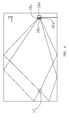
- FIG. 4 is a schematic, top view of a room where the multi-directional sound emission system of FIG. 1 is applied, showing sound broadcasting paths along two up and down directions;
- FIG. 5 is a schematic, side view of the room where the multi-directional sound emission system of FIG. 1 is applied, showing sound broadcasting paths along lateral directions;
- FIG. 6 is a schematic view of a first sound conduit of the multi-directional sound emission system of FIG. 2 ;
- FIG. 7 is a schematic view of a second sound conduit of the multi-directional sound emission system of FIG. 2 ;
- FIG. 8 is a schematic view of a third sound conduit of the multi-directional sound emission system of FIG. 2 ;
- FIG. 9 is a schematic view of a fourth sound conduit of the multi-directional sound emission system of FIG. 2 ;
- FIG. 10 is a schematic view of a fifth sound conduit of the multi-directional sound emission system of FIG. 2 ;
- FIG. 11 is a schematic view of a sixth sound conduit of the multi-directional sound emission system of FIG. 2 ;
- FIG. 12 is a schematic, isometric view of a multi-directional sound emission system according to a second embodiment of the present invention.
- FIG. 13 is a schematic, top view of a room where the multi-directional sound emission system of FIG. 1 is applied, showing a left surround effect and a right sound surround effect;
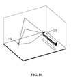
- FIG. 14 is a schematic, isometric view of the room where the multi-directional sound emission system of FIG. 12 is applied, showing sound broadcasting paths emitted from one sound emission means;
- FIG. 15 is a schematic, isometric view of a multi-directional sound emission system according to a third embodiment of the present invention.
- FIG. 16 is a schematic, isometric view of a mechanical sound conducting means of the multi-directional sound emission system of FIG. 15 ;
- FIG. 17 is a schematic, isometric view of a multi-directional sound emission system according to a fourth embodiment of the present invention.
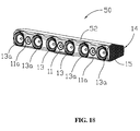
- FIG. 18 is a schematic, isometric view of a multi-directional sound emission system according to a fifth embodiment of the present invention.
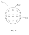
- FIG. 19 is a schematic, isometric view of a mechanical sound conducting means of the multi-directional sound emission system of FIG. 18 .
- the multi-directional sound emission system 10 comprises a speaker body 12 and sound emission devices 14 coupled to both ends of the speaker body 12.
- the sound emission devices 14 each include a sound emission means 16 for directionally emitting sound towards multiple directions.
- the sound emission means 16 includes a plurality of hollow mechanical sound conducting elements 18.
- Each hollow mechanical sound conducting element 18 has an inner opening end 182 and an exterior opening end 180 opposite to the inner opening end.
- the exterior opening ends 180 of the sound conducting elements 18 are directed towards desired multiple directions, respectively.
- the sound emission means 16 is configured for receiving sound signals from the speaker body 12 and emitting sound along the desired multiple directions through the sound conducting elements 18.
- the speaker body 12 and the sound emission devices 14 is integrated or configured as a whole.
- the multi-directional sound emission system 10 is substantially a three-channel sound system.
- the speaker body 12 is provided with a sound source device (not shown) for receiving sound input from external apparatus, e.g., a TV set or a DVD player.
- the speaker body 12 includes an audio middle frequency controller 11 and two speakers 13 coupled to both ends of the controller 11.
- the middle frequency controller 11 and the two speakers 13 cooperatively constitute a center channel.
- the sound emission devices 14 at both ends of the speaker body 12 e.g., at the left and right sides of the speaker body 12 respectively serve as a left surround channel and a right surround channel (the positions herein is referred to as the positions shown in the figures).
- the sound emission devices 14 at both ends of the speaker body 12 each have a sound emission means 16 for directionally emitting sound towards multiple directions.
- the sound emission devices 14 coupled to right side of the speaker body 12 includes a plurality of hollow mechanical sound conducting elements 18 radially distributed in a three-dimensional direction, thereby emitting sound along various directions in three-dimension.
- Each sound emission device 14 further includes a porous cover 15 configured for protecting the sound conducting elements 18 therein from being injured and allowing sound to pass through.
- the porous cover 15 is a metal or plastic mesh enclosure.
- the right porous cover 15 protecting the sound conducting elements 18 is removed away to show inner structure of the right sound emission device 14, while the left porous cover 15 is kept to cover the left sound conducting elements 18 therein.
- FIGS. 2 and 3 are a side view and a front view of the sound emission means 16, respectively.
- the sound emission means 16 includes a base 162 with a loudspeaker 164 and the plurality of mechanical sound conducting elements 18 thereon.
- the loudspeaker 164 has an opening 166 where the sound is emitted.
- the opening 166 is in sound communication with the plurality of mechanical sound conducting elements 18, e.g., with the inner opening ends 182 of the elements 18.
- the sound conducting elements 18 are sound conducting conduits 18.
- the sound conducting conduits 18 could be a hollow pipe with the inner opening end 182 and the exterior opening end 180 opposite to the inner opening end 182, as shown in FIGS. 2 and 3 .
- a sphere mask 165 is overlaid at the opening 166.
- each sound conducting conduit 18 is penetrated through the sphere mask 165 to be in sound communication with the loudspeaker 164 and the exterior opening end 180 is directed to outside.
- sound communication means that the sound from the opening 166 is propagated outwardly along the sound conducting elements 18.
- the opening 166 is in direct (e.g., gas) communication with the sound conducting conduits 18.
- the opening 166 is shielded with a vibrating membrane or a mesh mask. In this case, although the opening 166 is not in direct communication with the sound conducting conduits 18, the sound can be transferred to the sound conducting conduits 18, e.g., by means of vibration, and then spread out through the sound conducting conduits 18.
- the sound conducting conduits 18 are protruded out of the base 162 according to predetermined exit angle or position distribution, such as for example in a radially divergent form as shown in FIG. 3 .
- the plurality of sound conducting conduits 18 is in a spherical divergent form.
- the sound conducting conduits 18 extend along imaginary normal directions which are converged to a spherical center of the sphere mask 165.
- the spherical center of the sphere mask 165 is preferably a center of the opening 166.
- the sphere mask 165 could be a partial sphere or a quarter sphere (as shown in FIG. 3 ).
- the exterior opening ends 180 of the sound conducting conduits 18 are appeared as a spherical profile or a curved profile.
- the sound conducting conduits 18 includes a group of front sound conducting conduits 18a, a group of lateral sound conducting conduits 18b, a group of upper sound conducting conduits 18c, and a group of lower sound conducting conduits 18d.
- Each of the four groups of sound conducting conduits 18a includes at least one sound conducting conduit.
- the front sound conducting conduits 18a are directed to direct or biased front of the speaker body 12, for propagating sound along a forward direction.
- the openings of the front sound conducting conduits 18a face towards the direct or biased front of the speaker body 12.
- the front sound conducting conduits 18a on the right produce anterolateral sound wave and serve as a front right channel.
- the lateral sound conducting conduits 18b on the right are directed to direct or biased lateral of the speaker body 12, for propagating sound along a lateral direction.
- the openings of the lateral sound conducting conduits 18b face towards the direct or biased lateral of the speaker body 12.
- FIG. 5 if the sound emission system 10 is placed in a room, most of the sound waves from the lateral sound conducting conduits 18b are reflected towards a listening location 19 by side walls. Some sound waves from the lateral sound conducting conduits 18b are reflected twice, e.g., firstly towards a rear wall by the side walls and then towards the listening location 19 by the rear wall.
- the upper sound conducting conduits 18c are directed to direct or biased above of the speaker body 12, for propagating sound along an upward direction.
- the openings of the upper sound conducting conduits 18c face towards the direct or biased above of the speaker body 12.
- FIG. 4 again, if the sound emission system 10 is placed in a room, most of the sound waves from the upper sound conducting conduits 18c are reflected towards a listening location 19 by a ceiling. Some sound waves from the upper sound conducting conduits 18c are reflected twice, e.g., firstly towards the rear wall by the ceiling and then towards the listening location 19 by the rear wall.
- the lower sound conducting conduits 18d are directed to direct or biased below of the speaker body 12, for propagating sound along a downward direction.
- the openings of the lower sound conducting conduits 18d face towards the direct or biased below of the speaker body 12.
- FIG. 4 if the sound emission system 10 is placed in a room, most of the sound waves from the lower sound conducting conduits 18d are reflected towards a listening location 19 by a floor. Some sound waves from the lower sound conducting conduits 18d are reflected twice, e.g., firstly towards the floor by the floor and then towards the listening location 19 by the rear wall.
- the sound emission means 16 on the right serves as a right surround channel in relation to the listening location 19 by means of the four groups of sound conducting conduits 18a, 18b, 18c, 18d.
- the left sound emission means 16 has the same structure to the right sound emission means 16 and thus serves as a left surround channel in relation to the listening location 19 by means of similar four groups of sound conducting conduits on the left.
- the length of the sound conducting conduits 18 may be uniform or different from each other.
- the sizes of the openings of the sound conducting conduits 18 may be uniform or different from each other.
- the sound conducting conduits 18 are in a tubular shape.
- the tubular sound conducting conduits 18 have narrow openings (e.g., narrow opening end 180) and are elongated, and thus emit acute sound.
- the tubular sound conducting conduits 18 have large opening (e.g., large opening end 180) and are shorten, and thus emit mild and dull sound. It is to be understood that the sizes and shapes of the sound conducting conduits 18 could be designed according to actual demands.
- the length and opening diameters of the sound conducting conduits 18 and materials of the conduits could be selected to achieve desired quality, sound frequency, phase and interference of sound emitted therefrom. Therefore, the length and opening diameters of the sound conducting conduits 18 (the same to other following mechanical sound conducting elements) could be designed based on acoustic principle in physics. Further, the arrangement (e.g., divergent angles and intervals between the conduits) of the sound conducting conduits 18 on the base 162 could be designed based on acoustic principle in physics in accordance with actual demand.
- the sound conducting conduit 18 has the same shapes to that in FIG. 1 , namely the conduit 18 is a straight circular tube with uniform diameter.
- the sound conducting conduit 18 is similar to the conduit in FIG. 6 , except that the conduit 18 in FIG. 7 has a relatively larger length and smaller diameter than the conduit 18 in FIG. 6 .
- the sound conducting conduit 18 is a straight circular tube with a tapered structure from the outer opening end 180 to the inner opening end 182, like a trumpet. That is, the inner opening end 182 has a smaller diameter than the outer opening end 180.
- the sound conducting conduit 18 in FIG. 10 is a straight cubic tube with a tapered structure from the outer opening end 180 to the inner opening end 182.
- the sound conducting conduit 18 is substantially a straight tube and includes a drum-shaped portion and a narrow straight tubular portion.
- the narrow opening end has a relatively smaller diameter than the drum-shaped portion, and thus the sound conducting conduit 18 is provided with a large opening end and a narrow opening end opposite to the large opening end.
- the drum-shaped portion is substantially gyrorotor and includes three segments, e.g., an exterior end segment 181 with the large opening end, a drum segment 183 and a transition segment 185 coupling the drum segment 183 to narrow straight tubular portion.
- the sound conducting conduit 18 is seemed to be a conch or functioned as a conch.
- the sound emission means 16 could include any combination of these sound conducting conduits 18 with various shapes above-mentioned.
- the sound conducting conduits 18 are made of many kinds of available materials which aid in conduction and propagation of sound and have no influence on sound quality.
- the available materials could be a material used in typical musical instruments, for example, copper or wood.
- the cross section of the sound conducting conduit 18 could be in a polygon shape, for example, triangle, pentagon or more. It is to be appreciated that various variations about the sound conducting conduit are construed in the scope of the present invention.
- the sound emission device 14 is coupled to the speaker body 12 by means of mechanical engagement, for example, a snapping means, a welding means or a screw means.
- the base 162 of the sound emission means 16 is provided with a fastening member by that the base 162 is attached to the speaker body 12.
- the loudspeaker 164 is coupled to the speaker body 12 or the base 162 by means of mechanical engagement, for example, a snapping means, a welding means or a screw means.
- the sound conducting conduits 18 are coupled to the sphere mask 165 on the loudspeaker 164 by means of mechanical engagement, for example, a snapping means, a welding means or a screw means.
- each parts of the sound emission device 14 can be assembled together with the speaker body 12 by means of mechanical engagement, and thus do not require complex speaker structure and connection means, complicated digital process device and digital process circuit.
- the sound emission system 10 is easy to assemble and occupies small space.
- a multi-directional sound emission system 20 is shown in accordance with a second embodiment of the present invention.
- the multi-directional sound emission system 20 is similar to the above-described multi-directional sound emission system 10, except that the sound emission system 20 is a five-channel sound system.
- the reference numbers used in FIG.12 are similar to those in FIG. 1 and the parts designated by the same reference numbers to FIG. 1 are similar to those parts described above.
- the sound emission system 20 includes a speaker body 22 and the above two sound emission devices 14 coupled to both ends of the speaker body 22.
- the two sound emission devices 14 is respectively serve as a left surround channel and a right surround channel, as described above.
- the structure of the sound emission devices 14 is shown in FIGS. 1 through 11 .
- the speaker body 22 is provided with three channels, e.g., a front left channel, a front right channel and a center channel.
- the center channel includes the middle frequency controller 11 and the two speakers 13, similarly to those described above in the first embodiment.
- the front left channel and the front right channel are coupled to both ends of the center channel and have similar construction to the center channel.
- the left and right channels each include an audio middle frequency controller 11a and two speakers 13a respectively disposed at both ends of the middle frequency controller 11a.
- the middle frequency controller 11a and the two speakers 13a are respectively similar to the middle frequency controller 11 and the two speakers 13.
- the center channel, the front left channel, the front right channel, the left surround channel and the right surround channel constitute cooperatively constitute a five-channel structure of the sound emission system 20.
- the sound emission system 20 is essentially a 5.1ch surround sound system with the five channels integrated together with the speaker body 22 as a whole.
- the sound emission system 20 can be positioned adjacent to some music sources or display devices, for example, Television Set, Music Television (MTV), cinema screen to transfer the music or sound to the viewers or listeners by the five channels thereof, thereby achieving a 5.1ch surround effect. That is, in case that the sound emission system 20 is disposed at the front of the listener, the 5.1 ch surround effect is achieved without additional separate speakers. As shown in FIGS.
- part of sound transferred from the sound conducting conduits 18 is reflected towards the listener once by the sidewalls to form an imaginary side sound source, such that the listener (e.g., locating at the listening location 19) feels that this part of sound is emitted from both sides.
- Part of sound transferred from the sound conducting conduits 18 is reflected towards the listener once by the ceiling to form an imaginary top sound source, such that the listener feels that this part of sound is emitted from the ceiling.
- the present sound emission system 20 is devoid of a number of separate speakers surrounding the listening location 19, as required in the traditional sound devices.
- sound emission system 20 sound is transferred with directivity based on mechanical structure, e.g., the sound conducting conduits 18 such that the entire configuration of the system 20 is compact and easy to assemble, and thus is devoid of complex separate speakers, expensive digital process devices or complicated digital circuit. It is to be understood that some further sound emission means 16 could be arranged at desired portion of the speaker body 12, e.g., top of the speaker body 12 to achieve more than five sound channels, for example seven channels or more.
- FIGS. 15 and 16 a multi-directional sound emission system 30 is shown in accordance with a third embodiment of the present invention.
- the multi-directional sound emission system 30 is similar to the above-described multi-directional sound emission system 10, except that the sound emission means 36.
- the reference numbers used in FIGS. 15 and 16 are similar to those in FIG. 1 and the parts designated by the same reference numbers to FIG. 1 are similar to those parts described above.
- the sound emission means 36 has a plurality of mechanical sound conducting elements 38.
- the sound emission means 36 includes an enclosure 362 and a plurality of separators 364.
- the enclosure 362 is functioned as a base like the base 162.
- the enclosure 362 includes a top portion and a bottom portion respectively extending along a top surface and a bottom surface of the speaker body 12 and thus is in a hopper shape.
- the separators 364 are arranged in the enclosure 362 in an array form and are intersecting to each other, e.g., forming a crisscross arrangement.
- the array of separators 364 includes a vertical array of separators 364 and a horizontal array of separators 364.
- the vertical and horizontal arrays of separators 364 cooperatively define the plurality of mechanical sound conducting elements 38 therebetween. Accordingly, the mechanical sound conducting elements 38 are aligned in an array form.
- Each of the sound conducting elements 38 has a through-hole and may be a rectangular tube.
- the separators 364 may be a fan-shaped panel and thus form the sound conducting elements 38 with tapered cross-sectional size therebetween.
- the sound conducting elements 38 are similar to the rectangular sound conducting conduit 18 in FIG. 10 .
- the array of sound conducting elements 38 in FIG. 15 could be formed by assembling a number of rectangular sound conducting conduit 18 in FIG. 10 side by side, for example using solder or adhesive.
- the entire outer openings of the sound conducting elements 38 of the sound emission means 36 are appeared as a spherical profile or a curved profile.
- a loudspeaker is provided at the bottom (e.g., narrow end) of the enclosure 362 and is in sound communication with the sound source of the speaker body 12.
- the arrangement of the loudspeaker is similar to that of the loudspeaker 164, as shown in FIG. 2 , except that the rectangular sound conducting elements 38 radially extend along substantial converged imaginary normal directions.
- Each sound conducting element 18 has an inner opening end and an exterior opening end opposite to the inner opening end. The inner opening end of the sound conducting element 18 is in sound communication with the loudspeaker.
- the plurality of sound conducting elements 38 includes a group of front sound conducting conduits, a group of lateral sound conducting conduits, a group of upper sound conducting conduits, and a group of lower sound conducting conduits.
- Each of the four groups of sound conducting elements includes at least one rectangular sound conducting tube. In this way, the sound conducting elements 38 at both ends of the speaker body 12 form a left surround sound channel and a right sound channel relative to the listening location 19.
- FIG. 17 a multi-directional sound emission system 40 is shown in accordance with a fourth embodiment of the present invention.
- the multi-directional sound emission system 40 is essentially similar to the above-described multi-directional sound emission system 30, except that the sound emission system 40 is a five-channel sound system.
- the reference numbers used in FIG.17 are similar to those in FIGS. 15 and 16 and the parts designated by the same reference numbers to FIGS. 15 and 16 are similar to those parts described above.
- the five-channel sound system of the sound emission system 40 has the same structure to the five-channel sound system of the sound emission system 20.
- the multi-directional sound emission system 40 includes the above speaker body 22 and the above two sound emission devices 14 coupled to both ends of the speaker body 22.
- the speaker body 22 is similar to the speaker body 22 in FIG. 12 , e.g., including three pairs of center loudspeakers 13, 13a.
- the two sound emission devices 14 and the three pairs of center loudspeakers 13, 13a cooperatively constitute the five-channel sound system of the sound emission system 40.
- FIG. 18 a multi-directional sound emission system 50 is shown in accordance with a fifth embodiment of the present invention.
- the multi-directional sound emission system 50 is essentially similar to the above-described multi-directional sound emission system 20, except of the sound emission means 56.
- the reference numbers used in FIG.18 are similar to those in FIG. 12 and the parts designated by the same reference numbers to FIG. 12 are similar to those parts described above.
- the multi-directional sound emission system 50 includes a speaker body 52 and the above two sound emission devices 14 coupled to both ends of the speaker body 52.
- the speaker body 52 is similar to the speaker body 22 in FIG. 12 , except that the outline of the speaker body 52 is streamlined. That is, a casing of the speaker body 52 is provided with streamlined edges, but not straight linear edges as illustrated in FIG. 12 .
- FIG. 19 illustrates the sound emission means 56 of the multi-directional sound emission system 50.
- the sound emission means 56 is in a sphere shape and includes a spherical base 562.
- the base 562 could be in a shape of hemisphere, frustum of sphere, and the likes.
- the spherical base 562 defines a plurality of sound conducting through-holes 58 as mechanical sound conducting elements.
- the plurality of sound conducting through-holes 58 could be defined in part (e.g., half or quarter) of the spherical base 562.
- the sound conducting through-holes 58 usefully extend along radial directions which are converged to a spherical center of the spherical base 562.
- a loudspeaker may be disposed inside the spherical base 562, for example at a center thereof, or be attached the spherical base 562.
- Each sound conducting through-hole 58 is in sound communication with sound exit (e.g., opening 166 if FIG. 2 ) of the loudspeaker.
- the loudspeaker could be attached to a planar portion of the hemispherical sound emission means 56, similar to the arrangement of the loudspeaker 164 in FIG. 2 .
- Each sound conducting through-hole 58 has an exterior opening end and an inner opening end opposite to the exterior opening end. The inner opening end of the sound conducting through-hole 58 is in sound communication with sound exit of the loudspeaker.
- the sound conducting through-holes 58 are beneficially arranged in a uniform interval and have an identical or varying hole size.
- the sound conducting through-holes 58 include a group of front sound conducting through-holes, a group of lateral sound conducting through-holes, a group of upper sound conducting through-holes, and a group of lower sound conducting through-holes, thereby achieving a left surround sound channel and a right surround sound channel relative to the listening location.
- Each of the four groups of sound conducting through-holes includes at least one circular or rectangular through-hole. Accordingly, the sound conducting through-holes 58 and the three channels in the speaker body 52 cooperatively form a 5.1 ch surround sound system.
- the sound conducting conduits 18, the sound conducting conduits 38 and the sound conducting through-holes 58 described above could be replaced with one another but are not limited to be applied the above respective embodiments.
- the sound emission means could be designed to be a desired configuration for actual demands and be not limited to the above-mentioned structure.
- one sound emission system can achieve a multi-channel effect, for example, three-channel, five-channel, or more channels, by using the mechanical sound conducting means at both ends of the speaker body.
- the sound conducting means can allow the listener to receive sounds from a three-dimensional direction, for example, right front, lower front, both sides, top, backside of the listener, such that the listener feels that there are many imaginary loudspeakers around him/her and can enjoy a stereophonic effect with a plurality of channels.
- the multi-directional sound emission system achieves communication of sound by means of acoustic principle in physics and mechanical structure and is devoid of complex speaker devices, expensive digital process system, and complicated digital process circuit, which are required in traditional sound systems.
- Such a multi-directional sound emission system is compact in structure and is easy to assemble, thereby reducing cost in manufacture. Only one multi-directional sound emission system disposed to face towards the listener can achieve the stereophonic effect with a plurality of channels without any additional separate loudspeakers around the listener, thereby occupying small space in house and facilitating to carry away the sound emission system.
Abstract
Description
- The present invention relates to speaker devices and, more particularly, to a multi-directional sound emission system, which can generate a plurality of sound channels.
- With the increasing of people's life level, a demand for high-quality speaker systems has increased dramatically over the last twenty years. At present, a traditional speaker system generally can produce a stereophonic effect with a plurality of channels by setting a set of stereophonic speaker assembly.
- For example, a typical stereophonic speaker assembly includes a pair of primary loudspeakers and a pair of secondary separate loudspeakers to form four sound emission fields. However, such a speaker assembly is lack of a sense of three-dimensional depth. Stereophonic effect can only be enjoyed at a middle location between the two loudspeakers. If the listener is adjacent to one loudspeaker but is far from the other loudspeaker, the stereophonic effect is significantly decreased. Further, in this structure, the speaker assembly occupies a large space in a room and it is inconvenient to carry and move away.
- Some stereophonic speaker assemblies can achieve surround sound effect by a surround sound system. The surround sound system simulates a desired three-dimensional environment by directing sound to the listener from various orientations, including front, side, back, floor and ceiling propagation. Modem surround sound systems capitalize on diverse speakers to generate both stereophonic and multi-channel output, as well as synchronized shifting of isolated sounds to individual speakers disposed around the listener. For example, a speaker assembly is equipped with a speaker array constituting a 5.1ch surround sound system, e.g., a front left channel, a front right channel, a center channel, a rear left channel, a rear right channel, and a subwoofer LFE(Low Frequency Effects)ch.
- However, such speaker assembly with a speaker array requires a complex structure and technology, and at the same time this brings about many undue problems. For example, the wiring for coupling the loudspeakers to a sound source makes the room untidy. In effect, this complex speaker assembly has disadvantageous influence on interior decoration. Furthermore, requirement for multi-direction separate loudspeakers results in an expensive cost of such speaker assembly.
- At present, some speaker assemblies use a digital process technology to obtain desired surround sound effect. This digital speaker assembly typically includes a speaker array apparatus. The speaker array apparatus includes a plurality of speaker units from which audio is outputted and reflected with directivity against a predetermined wall surface or a reflection plate so as to form a virtual speaker. Each of the plurality of speaker units is independently driven so that an audio beam generated according to the input audio signal by a digital signal processor is emitted to a predetermined focal point position in a space. Although this digital speaker assembly enables realization of a wide listening range and a sound image positioning, it requires a very complex digital circuit system and various electronic elements. This increases complexity of design, as well as cost of the product. The high expensive product suppresses wide application of the digital speaker assemblies.
- There is, therefore, a need for a multi-directional sound emission system, which has a compact structure and a reduced cost, and is portable and easy to assemble.
- In accordance with an embodiment of the present invention, a multi-directional sound emission system comprises a speaker body and sound emission devices coupled to both ends of the speaker body. The sound emission devices each include a sound emission means for directionally emitting sound towards multiple directions. The sound emission means includes a plurality of hollow mechanical sound conducting elements. Each hollow mechanical sound conducting element has an inner opening end and an exterior opening end opposite to the inner opening end. The exterior opening ends of the sound conducting elements are directed towards desired multiple directions, respectively. The sound emission means is configured for receiving sound signals from the speaker body and emitting sound along the desired multiple directions through the sound conducting elements.
- In the above-described multi-directional sound emission system, sound from the speaker body (i.e., sound source) can be directed the desired multiple directions according to actual demands through the sound conducting elements. Thus, the listener situated at any position of a room can receive sound from multiple directions to obtain a stereophonic effect. The present multi-directional sound emission system has a combined sound body and sound emission means and thus is free of the multiple separate speakers which are required in traditional sound system. The plurality of hollow mechanical sound conducting elements integrated with the sound body can achieve a desired multi-channel output, without many complex speakers, expensive digital process devices or complicated digital circuit. The present multi-directional sound emission system has a compact structure and a reduced cost, and is portable and easy to assemble. The plurality of hollow mechanical sound conducting elements use acoustic principle to carry out a directive sound propagation, accordingly, multi-channel outputs can synchronously be achieved based on a single front sound body (sound source). Since the present system does not require additional separate speakers around the listener, thus greatly reducing space of the system. Further, it is also convenient for the system to readily carry away.
- Other objects, advantages and novel features of the present invention will become more apparent from the following detailed description when taken in conjunction with the accompanying drawings, in which:
-
FIG. 1 is a schematic, isometric view of a multi-directional sound emission system according to a first embodiment of the present invention; -
FIG. 2 is a schematic, side view of a sound emission means of the multi-directional sound emission system ofFIG. 1 ; -
FIG. 3 is a schematic, front view of the sound emission means of the multi-directional sound emission system ofFIG. 1 ; -
FIG. 4 is a schematic, top view of a room where the multi-directional sound emission system ofFIG. 1 is applied, showing sound broadcasting paths along two up and down directions; -
FIG. 5 is a schematic, side view of the room where the multi-directional sound emission system ofFIG. 1 is applied, showing sound broadcasting paths along lateral directions; -
FIG. 6 is a schematic view of a first sound conduit of the multi-directional sound emission system ofFIG. 2 ; -
FIG. 7 is a schematic view of a second sound conduit of the multi-directional sound emission system ofFIG. 2 ; -
FIG. 8 is a schematic view of a third sound conduit of the multi-directional sound emission system ofFIG. 2 ; -
FIG. 9 is a schematic view of a fourth sound conduit of the multi-directional sound emission system ofFIG. 2 ; -
FIG. 10 is a schematic view of a fifth sound conduit of the multi-directional sound emission system ofFIG. 2 ; -
FIG. 11 is a schematic view of a sixth sound conduit of the multi-directional sound emission system ofFIG. 2 ; -
FIG. 12 is a schematic, isometric view of a multi-directional sound emission system according to a second embodiment of the present invention; -
FIG. 13 is a schematic, top view of a room where the multi-directional sound emission system ofFIG. 1 is applied, showing a left surround effect and a right sound surround effect; -
FIG. 14 is a schematic, isometric view of the room where the multi-directional sound emission system ofFIG. 12 is applied, showing sound broadcasting paths emitted from one sound emission means; -
FIG. 15 is a schematic, isometric view of a multi-directional sound emission system according to a third embodiment of the present invention; -
FIG. 16 is a schematic, isometric view of a mechanical sound conducting means of the multi-directional sound emission system ofFIG. 15 ; -
FIG. 17 is a schematic, isometric view of a multi-directional sound emission system according to a fourth embodiment of the present invention; -
FIG. 18 is a schematic, isometric view of a multi-directional sound emission system according to a fifth embodiment of the present invention; and -
FIG. 19 is a schematic, isometric view of a mechanical sound conducting means of the multi-directional sound emission system ofFIG. 18 . - Objects, advantages and embodiments of the present invention will be explained below in detail with reference to the accompanying drawings. However, it is to be appreciated that the following description of the embodiment(s) is merely exemplary in nature and is no way intended to limit the invention, its application, or uses.
- Referring to
FIGS. 1 ,2 and 3 , a multi-directionalsound emission system 10 is shown in accordance with a first embodiment of the present invention. The multi-directionalsound emission system 10 comprises aspeaker body 12 andsound emission devices 14 coupled to both ends of thespeaker body 12. Thesound emission devices 14 each include a sound emission means 16 for directionally emitting sound towards multiple directions. The sound emission means 16 includes a plurality of hollow mechanicalsound conducting elements 18. Each hollow mechanicalsound conducting element 18 has aninner opening end 182 and anexterior opening end 180 opposite to the inner opening end. The exterior opening ends 180 of thesound conducting elements 18 are directed towards desired multiple directions, respectively. The sound emission means 16 is configured for receiving sound signals from thespeaker body 12 and emitting sound along the desired multiple directions through thesound conducting elements 18. - In the illustrated embodiment, the
speaker body 12 and thesound emission devices 14 is integrated or configured as a whole. As shown inFIG. 1 , the multi-directionalsound emission system 10 is substantially a three-channel sound system. Thespeaker body 12 is provided with a sound source device (not shown) for receiving sound input from external apparatus, e.g., a TV set or a DVD player. Thespeaker body 12 includes an audiomiddle frequency controller 11 and twospeakers 13 coupled to both ends of thecontroller 11. Themiddle frequency controller 11 and the twospeakers 13 cooperatively constitute a center channel. Thesound emission devices 14 at both ends of the speaker body 12 (e.g., at the left and right sides of the speaker body 12) respectively serve as a left surround channel and a right surround channel (the positions herein is referred to as the positions shown in the figures). - As shown in the
FIG. 1 , thesound emission devices 14 at both ends of thespeaker body 12 each have a sound emission means 16 for directionally emitting sound towards multiple directions. As seen inFIG. 1 , thesound emission devices 14 coupled to right side of thespeaker body 12 includes a plurality of hollow mechanicalsound conducting elements 18 radially distributed in a three-dimensional direction, thereby emitting sound along various directions in three-dimension. Eachsound emission device 14 further includes aporous cover 15 configured for protecting thesound conducting elements 18 therein from being injured and allowing sound to pass through. In an embodiment, theporous cover 15 is a metal or plastic mesh enclosure. InFIG. 1 , the rightporous cover 15 protecting thesound conducting elements 18 is removed away to show inner structure of the rightsound emission device 14, while the leftporous cover 15 is kept to cover the leftsound conducting elements 18 therein. -
FIGS. 2 and 3 are a side view and a front view of the sound emission means 16, respectively. The sound emission means 16 includes a base 162 with aloudspeaker 164 and the plurality of mechanicalsound conducting elements 18 thereon. Theloudspeaker 164 has anopening 166 where the sound is emitted. Theopening 166 is in sound communication with the plurality of mechanicalsound conducting elements 18, e.g., with the inner opening ends 182 of theelements 18. In an embodiment, thesound conducting elements 18 aresound conducting conduits 18. For example, thesound conducting conduits 18 could be a hollow pipe with theinner opening end 182 and theexterior opening end 180 opposite to theinner opening end 182, as shown inFIGS. 2 and 3 . Asphere mask 165 is overlaid at theopening 166. Theinner opening end 182 of eachsound conducting conduit 18 is penetrated through thesphere mask 165 to be in sound communication with theloudspeaker 164 and theexterior opening end 180 is directed to outside. Herein, "sound communication" means that the sound from theopening 166 is propagated outwardly along thesound conducting elements 18. For example, in one embodiment of the present invention, theopening 166 is in direct (e.g., gas) communication with thesound conducting conduits 18. In an alternative embodiment of the present invention, theopening 166 is shielded with a vibrating membrane or a mesh mask. In this case, although theopening 166 is not in direct communication with thesound conducting conduits 18, the sound can be transferred to thesound conducting conduits 18, e.g., by means of vibration, and then spread out through thesound conducting conduits 18. Advantageously, thesound conducting conduits 18 are protruded out of the base 162 according to predetermined exit angle or position distribution, such as for example in a radially divergent form as shown inFIG. 3 . In the illustrated embodiment, the plurality ofsound conducting conduits 18 is in a spherical divergent form. For example, thesound conducting conduits 18 extend along imaginary normal directions which are converged to a spherical center of thesphere mask 165. The spherical center of thesphere mask 165 is preferably a center of theopening 166. Thesphere mask 165 could be a partial sphere or a quarter sphere (as shown inFIG. 3 ). In this case, the exterior opening ends 180 of thesound conducting conduits 18 are appeared as a spherical profile or a curved profile. - As shown in
FIGS. 1 and4 , in the sound emission means 16 on the right, thesound conducting conduits 18 includes a group of frontsound conducting conduits 18a, a group of lateralsound conducting conduits 18b, a group of uppersound conducting conduits 18c, and a group of lowersound conducting conduits 18d. Each of the four groups ofsound conducting conduits 18a includes at least one sound conducting conduit. As shown inFIGS. 1 and4 , the frontsound conducting conduits 18a are directed to direct or biased front of thespeaker body 12, for propagating sound along a forward direction. For example, the openings of the frontsound conducting conduits 18a face towards the direct or biased front of thespeaker body 12. The frontsound conducting conduits 18a on the right produce anterolateral sound wave and serve as a front right channel. - The lateral
sound conducting conduits 18b on the right are directed to direct or biased lateral of thespeaker body 12, for propagating sound along a lateral direction. For example, the openings of the lateralsound conducting conduits 18b face towards the direct or biased lateral of thespeaker body 12. Referring toFIG. 5 , if thesound emission system 10 is placed in a room, most of the sound waves from the lateralsound conducting conduits 18b are reflected towards a listeninglocation 19 by side walls. Some sound waves from the lateralsound conducting conduits 18b are reflected twice, e.g., firstly towards a rear wall by the side walls and then towards the listeninglocation 19 by the rear wall. - As shown in
FIGS. 1 and4 , the uppersound conducting conduits 18c are directed to direct or biased above of thespeaker body 12, for propagating sound along an upward direction. For example, the openings of the uppersound conducting conduits 18c face towards the direct or biased above of thespeaker body 12. Referring toFIG. 4 again, if thesound emission system 10 is placed in a room, most of the sound waves from the uppersound conducting conduits 18c are reflected towards a listeninglocation 19 by a ceiling. Some sound waves from the uppersound conducting conduits 18c are reflected twice, e.g., firstly towards the rear wall by the ceiling and then towards the listeninglocation 19 by the rear wall. - Likewise, as shown in
FIGS. 1 and4 , the lowersound conducting conduits 18d are directed to direct or biased below of thespeaker body 12, for propagating sound along a downward direction. For example, the openings of the lowersound conducting conduits 18d face towards the direct or biased below of thespeaker body 12. Referring back toFIG. 4 , if thesound emission system 10 is placed in a room, most of the sound waves from the lowersound conducting conduits 18d are reflected towards a listeninglocation 19 by a floor. Some sound waves from the lowersound conducting conduits 18d are reflected twice, e.g., firstly towards the floor by the floor and then towards the listeninglocation 19 by the rear wall. - Accordingly, the sound emission means 16 on the right serves as a right surround channel in relation to the listening
location 19 by means of the four groups ofsound conducting conduits location 19 by means of similar four groups of sound conducting conduits on the left. - The length of the
sound conducting conduits 18 may be uniform or different from each other. The sizes of the openings of thesound conducting conduits 18 may be uniform or different from each other. In some embodiments, thesound conducting conduits 18 are in a tubular shape. The tubularsound conducting conduits 18 have narrow openings (e.g., narrow opening end 180) and are elongated, and thus emit acute sound. In other embodiments, the tubularsound conducting conduits 18 have large opening (e.g., large opening end 180) and are shorten, and thus emit mild and dull sound. It is to be understood that the sizes and shapes of thesound conducting conduits 18 could be designed according to actual demands. In addition, the length and opening diameters of thesound conducting conduits 18 and materials of the conduits could be selected to achieve desired quality, sound frequency, phase and interference of sound emitted therefrom. Therefore, the length and opening diameters of the sound conducting conduits 18 (the same to other following mechanical sound conducting elements) could be designed based on acoustic principle in physics. Further, the arrangement (e.g., divergent angles and intervals between the conduits) of thesound conducting conduits 18 on thebase 162 could be designed based on acoustic principle in physics in accordance with actual demand. - Referring to
FIGS. 6 through 11 , a variety ofsound conducting conduits 18 with various shapes are shown. As shown inFIG. 6 , thesound conducting conduit 18 has the same shapes to that inFIG. 1 , namely theconduit 18 is a straight circular tube with uniform diameter. InFIG. 7 , thesound conducting conduit 18 is similar to the conduit inFIG. 6 , except that theconduit 18 inFIG. 7 has a relatively larger length and smaller diameter than theconduit 18 inFIG. 6 . As shown inFIG. 8 , thesound conducting conduit 18 is a straight circular tube with a tapered structure from the outer openingend 180 to theinner opening end 182, like a trumpet. That is, theinner opening end 182 has a smaller diameter than the outer openingend 180. Thesound conducting conduit 18 inFIG. 9 is a curved circular tube with a tapered structure from the outer openingend 180 to theinner opening end 182, like a horn. Thesound conducting conduit 18 inFIG. 10 is a straight cubic tube with a tapered structure from the outer openingend 180 to theinner opening end 182. - Referring to
FIG. 11 , in an embodiment, thesound conducting conduit 18 is substantially a straight tube and includes a drum-shaped portion and a narrow straight tubular portion. The narrow opening end has a relatively smaller diameter than the drum-shaped portion, and thus thesound conducting conduit 18 is provided with a large opening end and a narrow opening end opposite to the large opening end. The drum-shaped portion is substantially gyrorotor and includes three segments, e.g., anexterior end segment 181 with the large opening end, adrum segment 183 and atransition segment 185 coupling thedrum segment 183 to narrow straight tubular portion. Thus, thesound conducting conduit 18 is seemed to be a conch or functioned as a conch. - In some embodiments, the sound emission means 16 could include any combination of these
sound conducting conduits 18 with various shapes above-mentioned. Thesound conducting conduits 18 are made of many kinds of available materials which aid in conduction and propagation of sound and have no influence on sound quality. The available materials could be a material used in typical musical instruments, for example, copper or wood. - It is to be understood that the cross section of the
sound conducting conduit 18 could be in a polygon shape, for example, triangle, pentagon or more. It is to be appreciated that various variations about the sound conducting conduit are construed in the scope of the present invention. - The
sound emission device 14 is coupled to thespeaker body 12 by means of mechanical engagement, for example, a snapping means, a welding means or a screw means. In an embodiment, thebase 162 of the sound emission means 16 is provided with a fastening member by that thebase 162 is attached to thespeaker body 12. Theloudspeaker 164 is coupled to thespeaker body 12 or the base 162 by means of mechanical engagement, for example, a snapping means, a welding means or a screw means. Advantageously, thesound conducting conduits 18 are coupled to thesphere mask 165 on theloudspeaker 164 by means of mechanical engagement, for example, a snapping means, a welding means or a screw means. Accordingly, each parts of thesound emission device 14 can be assembled together with thespeaker body 12 by means of mechanical engagement, and thus do not require complex speaker structure and connection means, complicated digital process device and digital process circuit. Thus, thesound emission system 10 is easy to assemble and occupies small space. - Referring to
FIG. 12 , a multi-directionalsound emission system 20 is shown in accordance with a second embodiment of the present invention. The multi-directionalsound emission system 20 is similar to the above-described multi-directionalsound emission system 10, except that thesound emission system 20 is a five-channel sound system. The reference numbers used inFIG.12 are similar to those inFIG. 1 and the parts designated by the same reference numbers toFIG. 1 are similar to those parts described above. - The
sound emission system 20 includes aspeaker body 22 and the above twosound emission devices 14 coupled to both ends of thespeaker body 22. The twosound emission devices 14 is respectively serve as a left surround channel and a right surround channel, as described above. The structure of thesound emission devices 14 is shown inFIGS. 1 through 11 . Thespeaker body 22 is provided with three channels, e.g., a front left channel, a front right channel and a center channel. The center channel includes themiddle frequency controller 11 and the twospeakers 13, similarly to those described above in the first embodiment. The front left channel and the front right channel are coupled to both ends of the center channel and have similar construction to the center channel. For example, the left and right channels each include an audiomiddle frequency controller 11a and twospeakers 13a respectively disposed at both ends of themiddle frequency controller 11a. Themiddle frequency controller 11a and the twospeakers 13a are respectively similar to themiddle frequency controller 11 and the twospeakers 13. In this way, the center channel, the front left channel, the front right channel, the left surround channel and the right surround channel constitute cooperatively constitute a five-channel structure of thesound emission system 20. - The
sound emission system 20 is essentially a 5.1ch surround sound system with the five channels integrated together with thespeaker body 22 as a whole. In practice, thesound emission system 20 can be positioned adjacent to some music sources or display devices, for example, Television Set, Music Television (MTV), cinema screen to transfer the music or sound to the viewers or listeners by the five channels thereof, thereby achieving a 5.1ch surround effect. That is, in case that thesound emission system 20 is disposed at the front of the listener, the 5.1 ch surround effect is achieved without additional separate speakers. As shown inFIGS. 13 and14 , part of sound transferred from thesound conducting conduits 18 is reflected towards the listener once by the sidewalls to form an imaginary side sound source, such that the listener (e.g., locating at the listening location 19) feels that this part of sound is emitted from both sides. Part of sound transferred from thesound conducting conduits 18 is reflected towards the listener once by the ceiling to form an imaginary top sound source, such that the listener feels that this part of sound is emitted from the ceiling. Part of sound transferred from thesound conducting conduits 18 is reflected towards the listener twice by the sidewalls or the ceiling and then by the rear wall to form an imaginary back sound source, such that the listener feels that this part of sound is emitted from back thereof Thus, the presentsound emission system 20 is devoid of a number of separate speakers surrounding the listeninglocation 19, as required in the traditional sound devices. - In the
sound emission system 20, sound is transferred with directivity based on mechanical structure, e.g., thesound conducting conduits 18 such that the entire configuration of thesystem 20 is compact and easy to assemble, and thus is devoid of complex separate speakers, expensive digital process devices or complicated digital circuit. It is to be understood that some further sound emission means 16 could be arranged at desired portion of thespeaker body 12, e.g., top of thespeaker body 12 to achieve more than five sound channels, for example seven channels or more. - Referring to
FIGS. 15 and16 , a multi-directional sound emission system 30 is shown in accordance with a third embodiment of the present invention. The multi-directional sound emission system 30 is similar to the above-described multi-directionalsound emission system 10, except that the sound emission means 36. The reference numbers used inFIGS. 15 and16 are similar to those inFIG. 1 and the parts designated by the same reference numbers toFIG. 1 are similar to those parts described above. The sound emission means 36 has a plurality of mechanicalsound conducting elements 38. - As shown in
FIG. 16 , the sound emission means 36 includes anenclosure 362 and a plurality ofseparators 364. Theenclosure 362 is functioned as a base like thebase 162. In the illustrated embodiment, theenclosure 362 includes a top portion and a bottom portion respectively extending along a top surface and a bottom surface of thespeaker body 12 and thus is in a hopper shape. Theseparators 364 are arranged in theenclosure 362 in an array form and are intersecting to each other, e.g., forming a crisscross arrangement. For example, the array ofseparators 364 includes a vertical array ofseparators 364 and a horizontal array ofseparators 364. The vertical and horizontal arrays ofseparators 364 cooperatively define the plurality of mechanicalsound conducting elements 38 therebetween. Accordingly, the mechanicalsound conducting elements 38 are aligned in an array form. Each of thesound conducting elements 38 has a through-hole and may be a rectangular tube. As shown inFIG. 16 , theseparators 364 may be a fan-shaped panel and thus form thesound conducting elements 38 with tapered cross-sectional size therebetween. In some embodiments, thesound conducting elements 38 are similar to the rectangularsound conducting conduit 18 inFIG. 10 . In another embodiment, the array ofsound conducting elements 38 inFIG. 15 could be formed by assembling a number of rectangularsound conducting conduit 18 inFIG. 10 side by side, for example using solder or adhesive. - The entire outer openings of the
sound conducting elements 38 of the sound emission means 36 are appeared as a spherical profile or a curved profile. A loudspeaker is provided at the bottom (e.g., narrow end) of theenclosure 362 and is in sound communication with the sound source of thespeaker body 12. The arrangement of the loudspeaker is similar to that of theloudspeaker 164, as shown inFIG. 2 , except that the rectangularsound conducting elements 38 radially extend along substantial converged imaginary normal directions. Eachsound conducting element 18 has an inner opening end and an exterior opening end opposite to the inner opening end. The inner opening end of thesound conducting element 18 is in sound communication with the loudspeaker. - The plurality of
sound conducting elements 38 includes a group of front sound conducting conduits, a group of lateral sound conducting conduits, a group of upper sound conducting conduits, and a group of lower sound conducting conduits. Each of the four groups of sound conducting elements includes at least one rectangular sound conducting tube. In this way, thesound conducting elements 38 at both ends of thespeaker body 12 form a left surround sound channel and a right sound channel relative to the listeninglocation 19. - Referring to
FIG. 17 , a multi-directional sound emission system 40 is shown in accordance with a fourth embodiment of the present invention. The multi-directional sound emission system 40 is essentially similar to the above-described multi-directional sound emission system 30, except that the sound emission system 40 is a five-channel sound system. The reference numbers used inFIG.17 are similar to those inFIGS. 15 and16 and the parts designated by the same reference numbers toFIGS. 15 and16 are similar to those parts described above. - The five-channel sound system of the sound emission system 40 has the same structure to the five-channel sound system of the
sound emission system 20. The multi-directional sound emission system 40 includes theabove speaker body 22 and the above twosound emission devices 14 coupled to both ends of thespeaker body 22. Thespeaker body 22 is similar to thespeaker body 22 inFIG. 12 , e.g., including three pairs ofcenter loudspeakers sound emission devices 14 and the three pairs ofcenter loudspeakers - Referring to
FIG. 18 , a multi-directionalsound emission system 50 is shown in accordance with a fifth embodiment of the present invention. The multi-directionalsound emission system 50 is essentially similar to the above-described multi-directionalsound emission system 20, except of the sound emission means 56. The reference numbers used inFIG.18 are similar to those inFIG. 12 and the parts designated by the same reference numbers toFIG. 12 are similar to those parts described above. - The multi-directional
sound emission system 50 includes aspeaker body 52 and the above twosound emission devices 14 coupled to both ends of thespeaker body 52. Thespeaker body 52 is similar to thespeaker body 22 inFIG. 12 , except that the outline of thespeaker body 52 is streamlined. That is, a casing of thespeaker body 52 is provided with streamlined edges, but not straight linear edges as illustrated inFIG. 12 . -
FIG. 19 illustrates the sound emission means 56 of the multi-directionalsound emission system 50. The sound emission means 56 is in a sphere shape and includes aspherical base 562. In an alternative embodiment, thebase 562 could be in a shape of hemisphere, frustum of sphere, and the likes. Thespherical base 562 defines a plurality of sound conducting through-holes 58 as mechanical sound conducting elements. The plurality of sound conducting through-holes 58 could be defined in part (e.g., half or quarter) of thespherical base 562. The sound conducting through-holes 58 usefully extend along radial directions which are converged to a spherical center of thespherical base 562. It is to be understood that the arrangement of the sound conducting through-holes 58 defined in thespherical base 562 could be designed according to actual demands. A loudspeaker may be disposed inside thespherical base 562, for example at a center thereof, or be attached thespherical base 562. Each sound conducting through-hole 58 is in sound communication with sound exit (e.g., opening 166 ifFIG. 2 ) of the loudspeaker. In case that the sound emission means 56 is in a hemisphere shape, the loudspeaker could be attached to a planar portion of the hemispherical sound emission means 56, similar to the arrangement of theloudspeaker 164 inFIG. 2 . Each sound conducting through-hole 58 has an exterior opening end and an inner opening end opposite to the exterior opening end. The inner opening end of the sound conducting through-hole 58 is in sound communication with sound exit of the loudspeaker. - The sound conducting through-
holes 58 are beneficially arranged in a uniform interval and have an identical or varying hole size. The sound conducting through-holes 58 include a group of front sound conducting through-holes, a group of lateral sound conducting through-holes, a group of upper sound conducting through-holes, and a group of lower sound conducting through-holes, thereby achieving a left surround sound channel and a right surround sound channel relative to the listening location. Each of the four groups of sound conducting through-holes includes at least one circular or rectangular through-hole. Accordingly, the sound conducting through-holes 58 and the three channels in thespeaker body 52 cooperatively form a 5.1 ch surround sound system. - The
sound conducting conduits 18, thesound conducting conduits 38 and the sound conducting through-holes 58 described above could be replaced with one another but are not limited to be applied the above respective embodiments. The sound emission means could be designed to be a desired configuration for actual demands and be not limited to the above-mentioned structure. - In these multi-directional sound emission system described above, one sound emission system can achieve a multi-channel effect, for example, three-channel, five-channel, or more channels, by using the mechanical sound conducting means at both ends of the speaker body. The sound conducting means can allow the listener to receive sounds from a three-dimensional direction, for example, right front, lower front, both sides, top, backside of the listener, such that the listener feels that there are many imaginary loudspeakers around him/her and can enjoy a stereophonic effect with a plurality of channels. The multi-directional sound emission system achieves communication of sound by means of acoustic principle in physics and mechanical structure and is devoid of complex speaker devices, expensive digital process system, and complicated digital process circuit, which are required in traditional sound systems. Such a multi-directional sound emission system is compact in structure and is easy to assemble, thereby reducing cost in manufacture. Only one multi-directional sound emission system disposed to face towards the listener can achieve the stereophonic effect with a plurality of channels without any additional separate loudspeakers around the listener, thereby occupying small space in house and facilitating to carry away the sound emission system.
- The present invention may be embodied in other forms without departing from the spirit or novel characteristics thereof. The embodiments disclosed in this application are to be considered in all respects as illustrative and not limitative. The scope of the invention is indicated by the appended claims rather than by the foregoing description; and all changes which come within the meaning and range of equivalency of the claims are intended to be embraced therein.
Claims (15)
- A multi-directional sound emission system, comprising:a speaker body;sound emission devices coupled to both ends of the speaker body, each sound emission device comprising a sound emission means configured for directionally emitting sound towards multiple directions, the sound emission means comprising a plurality of hollow mechanical sound conducting elements, each hollow mechanical sound conducting element having an inner opening end and an exterior opening end opposite to the inner opening end, the exterior opening ends of the sound conducting elements being directed towards desired multiple directions, respectively, the sound emission means being configured for receiving sound signals from the speaker body and emitting sound along the desired multiple directions through the sound conducting elements.
- The multi-directional sound emission system according to claim 1, wherein a loudspeaker for receiving the sound signals from the speaker body is disposed at the sound emission means, the inner opening ends of the plurality of mechanical sound conducting elements being in sound communication with the loudspeaker.
- The multi-directional sound emission system according to claim 1, wherein the sound emission means further comprises a base, the plurality of mechanical sound conducting elements radially extending out of the base.
- The multi-directional sound emission system according to claim 3, wherein the plurality of mechanical sound conducting elements are radially distributed in a three-dimensional direction to emit sound along a plurality of directions in three-dimension.
- The multi-directional sound emission system according to claim 3, wherein the mechanical sound conducting elements are sound conducting conduits radially extending out of the base.
- The multi-directional sound emission system according to claim 5, wherein the sound conducting conduit is selected from the group consisting of: a straight tube, a curved tube, a tapered tube, a tube with a drum-shaped portion, and a tube with a rectangular opening.
- The multi-directional sound emission system according to claim 3, wherein the base is in a shape selected from the group consisting of: sphere, hemisphere, frustum of sphere, and enclosure.
- The multi-directional sound emission system according to claim 3, wherein the base is an enclosure, a plurality of separators being arranged in an array in the enclosure and being intersecting to each other to define the sound conducting elements therebetween.
- The multi-directional sound emission system according to claim 3, wherein the base is in a shape selected from the group consisting of: sphere, hemisphere, frustum of sphere, the base defining a plurality of sound conducting through-holes radially extending outwardly as the mechanical sound conducting elements.
- The multi-directional sound emission system according to claim 1, wherein the plurality of mechanical sound conducting elements comprises a group of front sound conducting elements, a group of lateral sound conducting elements, a group of upper sound conducting elements, and a group of lower sound conducting elements, the front sound conducting elements being directed to direct or biased front of the speaker body for propagating sound along a forward direction, the lateral sound conducting elements being directed to direct or biased lateral of the speaker body for propagating sound along a lateral direction, the upper sound conducting elements being directed to direct or biased above of the speaker body for propagating sound along an upward direction, the lower sound conducting elements being directed to direct or biased below of the speaker body for propagating sound along a downward direction.
- The multi-directional sound emission system according to claim 1, wherein the speaker body and the sound emission devices coupled to both ends thereof are integrated as a whole.
- The multi-directional sound emission system according to claim 1, wherein the speaker body comprises at least one channel, each channel comprising an audio middle frequency controller and two speakers coupled to both ends of the middle frequency controller.
- The multi-directional sound emission system according to claim 1, wherein the mechanical sound conducting elements are configured for forming a left surround sound channel or a right surround sound channel.
- The multi-directional sound emission system according to claim 1, wherein the exterior opening ends of the sound conducting elements are appeared as a spherical profile or a curved profile.
- The multi-directional sound emission system according to claim 2, wherein the loudspeaker has an opening where the sound is emitted, the opening being in sound communication with the plurality of mechanical sound conducting elements, a mask being overlaid at the opening, the inner opening end of each sound conducting conduit being penetrated through the sphere mask to be in sound communication with the loudspeaker.
Applications Claiming Priority (1)
| Application Number | Priority Date | Filing Date | Title |
|---|---|---|---|
| CN2009101090409A CN101964937A (en) | 2009-07-23 | 2009-07-23 | Multi-directional sound-producing system |
Publications (3)
| Publication Number | Publication Date |
|---|---|
| EP2293596A2 true EP2293596A2 (en) | 2011-03-09 |
| EP2293596A3 EP2293596A3 (en) | 2012-08-29 |
| EP2293596B1 EP2293596B1 (en) | 2014-09-03 |
Family
ID=42830421
Family Applications (1)
| Application Number | Title | Priority Date | Filing Date |
|---|---|---|---|
| EP10155857.5A Not-in-force EP2293596B1 (en) | 2009-07-23 | 2010-03-09 | Multi-directional sound emission system |
Country Status (4)
| Country | Link |
|---|---|
| US (1) | US8351639B2 (en) |
| EP (1) | EP2293596B1 (en) |
| CN (1) | CN101964937A (en) |
| WO (1) | WO2011009309A1 (en) |
Cited By (2)
| Publication number | Priority date | Publication date | Assignee | Title |
|---|---|---|---|---|
| US10863276B2 (en) | 2015-08-03 | 2020-12-08 | Fraunhofer-Gesellschaft Zur Foerderung Der Angewandten Forschung E.V. | Soundbar |
| WO2022221582A1 (en) * | 2021-04-14 | 2022-10-20 | Dolby Laboratories Licensing Corporation | Narrow aperture waveguide loudspeaker for use with flat panel display devices |
Families Citing this family (14)
| Publication number | Priority date | Publication date | Assignee | Title |
|---|---|---|---|---|
| JP5626461B2 (en) * | 2011-05-11 | 2014-11-19 | パナソニック株式会社 | Video display device |
| US20150083189A1 (en) * | 2013-06-28 | 2015-03-26 | New Energy Technologies, Inc. | Coatings for aircraft fuselage surfaces to produce electricity for mission-critical systems on military aircraft |
| US20150030805A1 (en) * | 2013-07-29 | 2015-01-29 | Compagnie Chomarat | Composite bi-angle and thin-ply laminate tapes and methods for manufacturing and using the same |
| US11070918B2 (en) * | 2016-06-10 | 2021-07-20 | Ssv Works, Inc. | Sound bar with improved sound distribution |
| EP3491839A4 (en) * | 2016-08-01 | 2020-02-19 | D&M Holdings, Inc. | Soundbar having single interchangeable mounting surface and multi-directional audio output |
| CN107249161A (en) * | 2016-11-01 | 2017-10-13 | 佛山市创思特音响有限公司 | Linear array full range sound column |
| JP6607220B2 (en) | 2017-03-17 | 2019-11-20 | ヤマハ株式会社 | Speaker position specifying system, speaker position specifying device, and speaker position specifying method |
| CN106961646A (en) * | 2017-04-09 | 2017-07-18 | 嘉兴新博信息科技有限公司 | A kind of vehicle-mounted music automatic player |
| JP6904031B2 (en) * | 2017-04-13 | 2021-07-14 | ヤマハ株式会社 | Speaker position detection system, speaker position detection device, and speaker position detection method |
| US11070909B2 (en) | 2017-08-31 | 2021-07-20 | Harman International Industries, Incorporated | Speaker apparatus, method for processing input signals thereof, and audio system |
| US10544933B2 (en) | 2018-04-04 | 2020-01-28 | Abl Ip Holding Llc | Light fixture with rotatable speakers |
| USD883548S1 (en) | 2018-04-27 | 2020-05-05 | Abl Ip Holding Llc | Light fixture with rotatable end |
| KR20210054682A (en) | 2019-11-06 | 2021-05-14 | 삼성전자주식회사 | Loudspeaker and sound outputting apparatus having the same |
| WO2022236240A2 (en) * | 2021-05-05 | 2022-11-10 | Sonos, Inc. | Waveguides for side-firing audio transducers |
Family Cites Families (19)
| Publication number | Priority date | Publication date | Assignee | Title |
|---|---|---|---|---|
| US526046A (en) * | 1894-09-18 | mckelvey | ||
| US4673057A (en) * | 1984-11-13 | 1987-06-16 | Glassco John M | Geometrical transducer arrangements |
| US5137110A (en) * | 1990-08-30 | 1992-08-11 | University Of Colorado Foundation, Inc. | Highly directional sound projector and receiver apparatus |
| JP3104073B2 (en) * | 1990-12-22 | 2000-10-30 | ソニー株式会社 | Speaker device of television receiver |
| JPH07177443A (en) * | 1993-12-16 | 1995-07-14 | Toshiba Corp | Speaker system for television set |
| US6079515A (en) * | 1995-05-30 | 2000-06-27 | Newman; Ottis G. | Speaker enclosure |
| US7010138B1 (en) * | 1996-09-03 | 2006-03-07 | New Transducers Limited | Loudspeakers |
| CN1247045C (en) * | 1997-10-10 | 2006-03-22 | 三星电子株式会社 | Universal loadspeaker system |
| US6038330A (en) * | 1998-02-20 | 2000-03-14 | Meucci, Jr.; Robert James | Virtual sound headset and method for simulating spatial sound |
| CN2489531Y (en) * | 2001-04-30 | 2002-05-01 | 梁垣明 | Multi-azimuthal artificial stone loudspeaker box |
| CN2580716Y (en) * | 2002-10-18 | 2003-10-15 | 祝天祥 | All point direction and horn-like speaker |
| CN2631173Y (en) * | 2003-03-17 | 2004-08-04 | 视讯联合科技股份有限公司 | Multi channel circulating sound box |
| FI116506B (en) * | 2003-07-08 | 2005-11-30 | Harri Hietala | Omnidirectional stereo speaker |
| US7356155B2 (en) * | 2003-07-18 | 2008-04-08 | Lazarus Technologies, Inc. | Device and method for assisting vocalists in hearing their vocal sounds |
| CN2792070Y (en) * | 2005-05-14 | 2006-06-28 | 深圳东原电子有限公司 | High pitch loudspeaker with multiway diffusion function |
| CN2824486Y (en) * | 2005-10-28 | 2006-10-04 | 梁荣锵 | Multi-channel integrated loudspeaker box |
| GB2437125B (en) * | 2006-04-13 | 2011-02-09 | Gp Acoustics | Phase plug for compression driver |
| CN200969665Y (en) * | 2006-07-14 | 2007-10-31 | 梁荣锵 | Integrated loudspeaker box |
| CN101420648A (en) * | 2007-10-26 | 2009-04-29 | 捷音特科技股份有限公司 | Multi-channel loudspeaker |
-
2009
- 2009-07-23 CN CN2009101090409A patent/CN101964937A/en active Pending
-
2010
- 2010-02-03 US US12/699,326 patent/US8351639B2/en not_active Expired - Fee Related
- 2010-03-09 EP EP10155857.5A patent/EP2293596B1/en not_active Not-in-force
- 2010-03-31 WO PCT/CN2010/071453 patent/WO2011009309A1/en active Application Filing
Non-Patent Citations (1)
| Title |
|---|
| None |
Cited By (2)
| Publication number | Priority date | Publication date | Assignee | Title |
|---|---|---|---|---|
| US10863276B2 (en) | 2015-08-03 | 2020-12-08 | Fraunhofer-Gesellschaft Zur Foerderung Der Angewandten Forschung E.V. | Soundbar |
| WO2022221582A1 (en) * | 2021-04-14 | 2022-10-20 | Dolby Laboratories Licensing Corporation | Narrow aperture waveguide loudspeaker for use with flat panel display devices |
Also Published As
| Publication number | Publication date |
|---|---|
| CN101964937A (en) | 2011-02-02 |
| US8351639B2 (en) | 2013-01-08 |
| EP2293596B1 (en) | 2014-09-03 |
| US20110019844A1 (en) | 2011-01-27 |
| WO2011009309A1 (en) | 2011-01-27 |
| EP2293596A3 (en) | 2012-08-29 |
Similar Documents
| Publication | Publication Date | Title |
|---|---|---|
| US8351639B2 (en) | Multi-directional sound emission system | |
| US8351640B2 (en) | Multi-directional sound emission means and multi-directional sound emission system | |
| JP4127156B2 (en) | Audio playback device, line array speaker unit, and audio playback method | |
| RU2573037C2 (en) | Loudspeaker device having circular funnel-like sound outlet opening | |
| US5764777A (en) | Four dimensional acoustical audio system | |
| US6996243B2 (en) | Loudspeaker with shaped sound field | |
| US20060204022A1 (en) | Sound beam loudspeaker system | |
| EP0605224A1 (en) | Television set speaker system | |
| US8081775B2 (en) | Loudspeaker apparatus for radiating acoustic waves in a hemisphere around the centre axis | |
| JP2018527808A (en) | Sound bar | |
| US20160157010A1 (en) | Variable device for directing sound wavefronts | |
| WO2018231269A1 (en) | Speaker system for high fidelity reproduction of audio signals | |
| JP2013513266A (en) | Flat speaker | |
| JP5215299B2 (en) | Speaker system having at least two speaker devices and one unit for processing audio content signals | |
| JP2004179711A (en) | Loudspeaker system and sound reproduction method | |
| US20060251271A1 (en) | Ceiling Mounted Loudspeaker System | |
| JP2007506323A (en) | Digital speaker | |
| JPH06284488A (en) | Speaker system for television set | |
| US20140177883A1 (en) | Total Angle 360-Angled Loudspeaker Cabinet Enclosure Designing Technology | |
| JP2008167045A (en) | Speaker system | |
| CN201550267U (en) | Multidirectional sounding structure and multidirectional sounding system | |
| CN116405838A (en) | Sound display integrated device and sound image distance adjusting method | |
| KR19990004458A (en) | Loudspeaker system |
Legal Events
| Date | Code | Title | Description |
|---|---|---|---|
| PUAI | Public reference made under article 153(3) epc to a published international application that has entered the european phase |
Free format text: ORIGINAL CODE: 0009012 |
|
| AK | Designated contracting states |
Kind code of ref document: A2 Designated state(s): AT BE BG CH CY CZ DE DK EE ES FI FR GB GR HR HU IE IS IT LI LT LU LV MC MK MT NL NO PL PT RO SE SI SK SM TR |
|
| AX | Request for extension of the european patent |
Extension state: AL BA ME RS |
|
| 17P | Request for examination filed |
Effective date: 20120322 |
|
| PUAL | Search report despatched |
Free format text: ORIGINAL CODE: 0009013 |
|
| AK | Designated contracting states |
Kind code of ref document: A3 Designated state(s): AT BE BG CH CY CZ DE DK EE ES FI FR GB GR HR HU IE IS IT LI LT LU LV MC MK MT NL NO PL PT RO SE SI SK SM TR |
|
| AX | Request for extension of the european patent |
Extension state: AL BA ME RS |
|
| RIC1 | Information provided on ipc code assigned before grant |
Ipc: H04R 1/34 20060101ALI20120724BHEP Ipc: H04R 5/02 20060101AFI20120724BHEP |
|
| 17Q | First examination report despatched |
Effective date: 20130806 |
|
| GRAP | Despatch of communication of intention to grant a patent |
Free format text: ORIGINAL CODE: EPIDOSNIGR1 |
|
| INTG | Intention to grant announced |
Effective date: 20140314 |
|
| GRAS | Grant fee paid |
Free format text: ORIGINAL CODE: EPIDOSNIGR3 |
|
| GRAA | (expected) grant |
Free format text: ORIGINAL CODE: 0009210 |
|
| AK | Designated contracting states |
Kind code of ref document: B1 Designated state(s): AT BE BG CH CY CZ DE DK EE ES FI FR GB GR HR HU IE IS IT LI LT LU LV MC MK MT NL NO PL PT RO SE SI SK SM TR |
|
| REG | Reference to a national code |
Ref country code: GB Ref legal event code: FG4D |
|
| REG | Reference to a national code |
Ref country code: AT Ref legal event code: REF Ref document number: 686142 Country of ref document: AT Kind code of ref document: T Effective date: 20140915 Ref country code: CH Ref legal event code: EP |
|
| REG | Reference to a national code |
Ref country code: IE Ref legal event code: FG4D |
|
| REG | Reference to a national code |
Ref country code: DE Ref legal event code: R096 Ref document number: 602010018655 Country of ref document: DE Effective date: 20141016 |
|
| REG | Reference to a national code |
Ref country code: AT Ref legal event code: MK05 Ref document number: 686142 Country of ref document: AT Kind code of ref document: T Effective date: 20140903 |
|
| PG25 | Lapsed in a contracting state [announced via postgrant information from national office to epo] |
Ref country code: NO Free format text: LAPSE BECAUSE OF FAILURE TO SUBMIT A TRANSLATION OF THE DESCRIPTION OR TO PAY THE FEE WITHIN THE PRESCRIBED TIME-LIMIT Effective date: 20141203 Ref country code: SE Free format text: LAPSE BECAUSE OF FAILURE TO SUBMIT A TRANSLATION OF THE DESCRIPTION OR TO PAY THE FEE WITHIN THE PRESCRIBED TIME-LIMIT Effective date: 20140903 Ref country code: GR Free format text: LAPSE BECAUSE OF FAILURE TO SUBMIT A TRANSLATION OF THE DESCRIPTION OR TO PAY THE FEE WITHIN THE PRESCRIBED TIME-LIMIT Effective date: 20141204 Ref country code: FI Free format text: LAPSE BECAUSE OF FAILURE TO SUBMIT A TRANSLATION OF THE DESCRIPTION OR TO PAY THE FEE WITHIN THE PRESCRIBED TIME-LIMIT Effective date: 20140903 Ref country code: ES Free format text: LAPSE BECAUSE OF FAILURE TO SUBMIT A TRANSLATION OF THE DESCRIPTION OR TO PAY THE FEE WITHIN THE PRESCRIBED TIME-LIMIT Effective date: 20140903 Ref country code: LT Free format text: LAPSE BECAUSE OF FAILURE TO SUBMIT A TRANSLATION OF THE DESCRIPTION OR TO PAY THE FEE WITHIN THE PRESCRIBED TIME-LIMIT Effective date: 20140903 |
|
| REG | Reference to a national code |
Ref country code: NL Ref legal event code: VDEP Effective date: 20140903 |
|
| REG | Reference to a national code |
Ref country code: LT Ref legal event code: MG4D |
|
| PG25 | Lapsed in a contracting state [announced via postgrant information from national office to epo] |
Ref country code: AT Free format text: LAPSE BECAUSE OF FAILURE TO SUBMIT A TRANSLATION OF THE DESCRIPTION OR TO PAY THE FEE WITHIN THE PRESCRIBED TIME-LIMIT Effective date: 20140903 Ref country code: LV Free format text: LAPSE BECAUSE OF FAILURE TO SUBMIT A TRANSLATION OF THE DESCRIPTION OR TO PAY THE FEE WITHIN THE PRESCRIBED TIME-LIMIT Effective date: 20140903 Ref country code: HR Free format text: LAPSE BECAUSE OF FAILURE TO SUBMIT A TRANSLATION OF THE DESCRIPTION OR TO PAY THE FEE WITHIN THE PRESCRIBED TIME-LIMIT Effective date: 20140903 Ref country code: CY Free format text: LAPSE BECAUSE OF FAILURE TO SUBMIT A TRANSLATION OF THE DESCRIPTION OR TO PAY THE FEE WITHIN THE PRESCRIBED TIME-LIMIT Effective date: 20140903 |
|
| REG | Reference to a national code |
Ref country code: FR Ref legal event code: PLFP Year of fee payment: 6 |
|
| PG25 | Lapsed in a contracting state [announced via postgrant information from national office to epo] |
Ref country code: NL Free format text: LAPSE BECAUSE OF FAILURE TO SUBMIT A TRANSLATION OF THE DESCRIPTION OR TO PAY THE FEE WITHIN THE PRESCRIBED TIME-LIMIT Effective date: 20140903 |
|
| PG25 | Lapsed in a contracting state [announced via postgrant information from national office to epo] |
Ref country code: IS Free format text: LAPSE BECAUSE OF FAILURE TO SUBMIT A TRANSLATION OF THE DESCRIPTION OR TO PAY THE FEE WITHIN THE PRESCRIBED TIME-LIMIT Effective date: 20150103 Ref country code: CZ Free format text: LAPSE BECAUSE OF FAILURE TO SUBMIT A TRANSLATION OF THE DESCRIPTION OR TO PAY THE FEE WITHIN THE PRESCRIBED TIME-LIMIT Effective date: 20140903 Ref country code: EE Free format text: LAPSE BECAUSE OF FAILURE TO SUBMIT A TRANSLATION OF THE DESCRIPTION OR TO PAY THE FEE WITHIN THE PRESCRIBED TIME-LIMIT Effective date: 20140903 Ref country code: SK Free format text: LAPSE BECAUSE OF FAILURE TO SUBMIT A TRANSLATION OF THE DESCRIPTION OR TO PAY THE FEE WITHIN THE PRESCRIBED TIME-LIMIT Effective date: 20140903 Ref country code: RO Free format text: LAPSE BECAUSE OF FAILURE TO SUBMIT A TRANSLATION OF THE DESCRIPTION OR TO PAY THE FEE WITHIN THE PRESCRIBED TIME-LIMIT Effective date: 20140903 Ref country code: PT Free format text: LAPSE BECAUSE OF FAILURE TO SUBMIT A TRANSLATION OF THE DESCRIPTION OR TO PAY THE FEE WITHIN THE PRESCRIBED TIME-LIMIT Effective date: 20150105 |
|
| PG25 | Lapsed in a contracting state [announced via postgrant information from national office to epo] |
Ref country code: PL Free format text: LAPSE BECAUSE OF FAILURE TO SUBMIT A TRANSLATION OF THE DESCRIPTION OR TO PAY THE FEE WITHIN THE PRESCRIBED TIME-LIMIT Effective date: 20140903 |
|
| REG | Reference to a national code |
Ref country code: DE Ref legal event code: R097 Ref document number: 602010018655 Country of ref document: DE |
|
| PLBE | No opposition filed within time limit |
Free format text: ORIGINAL CODE: 0009261 |
|
| STAA | Information on the status of an ep patent application or granted ep patent |
Free format text: STATUS: NO OPPOSITION FILED WITHIN TIME LIMIT |
|
| PG25 | Lapsed in a contracting state [announced via postgrant information from national office to epo] |
Ref country code: DK Free format text: LAPSE BECAUSE OF FAILURE TO SUBMIT A TRANSLATION OF THE DESCRIPTION OR TO PAY THE FEE WITHIN THE PRESCRIBED TIME-LIMIT Effective date: 20140903 |
|
| 26N | No opposition filed |
Effective date: 20150604 |
|
| PG25 | Lapsed in a contracting state [announced via postgrant information from national office to epo] |
Ref country code: MC Free format text: LAPSE BECAUSE OF FAILURE TO SUBMIT A TRANSLATION OF THE DESCRIPTION OR TO PAY THE FEE WITHIN THE PRESCRIBED TIME-LIMIT Effective date: 20140903 Ref country code: LU Free format text: LAPSE BECAUSE OF FAILURE TO SUBMIT A TRANSLATION OF THE DESCRIPTION OR TO PAY THE FEE WITHIN THE PRESCRIBED TIME-LIMIT Effective date: 20150309 |
|
| REG | Reference to a national code |
Ref country code: CH Ref legal event code: PL |
|
| GBPC | Gb: european patent ceased through non-payment of renewal fee |
Effective date: 20150309 |
|
| PG25 | Lapsed in a contracting state [announced via postgrant information from national office to epo] |
Ref country code: SI Free format text: LAPSE BECAUSE OF FAILURE TO SUBMIT A TRANSLATION OF THE DESCRIPTION OR TO PAY THE FEE WITHIN THE PRESCRIBED TIME-LIMIT Effective date: 20140903 |
|
| REG | Reference to a national code |
Ref country code: IE Ref legal event code: MM4A |
|
| PG25 | Lapsed in a contracting state [announced via postgrant information from national office to epo] |
Ref country code: LI Free format text: LAPSE BECAUSE OF NON-PAYMENT OF DUE FEES Effective date: 20150331 Ref country code: CH Free format text: LAPSE BECAUSE OF NON-PAYMENT OF DUE FEES Effective date: 20150331 Ref country code: GB Free format text: LAPSE BECAUSE OF NON-PAYMENT OF DUE FEES Effective date: 20150309 Ref country code: IE Free format text: LAPSE BECAUSE OF NON-PAYMENT OF DUE FEES Effective date: 20150309 |
|
| REG | Reference to a national code |
Ref country code: FR Ref legal event code: PLFP Year of fee payment: 7 |
|
| PG25 | Lapsed in a contracting state [announced via postgrant information from national office to epo] |
Ref country code: BE Free format text: LAPSE BECAUSE OF FAILURE TO SUBMIT A TRANSLATION OF THE DESCRIPTION OR TO PAY THE FEE WITHIN THE PRESCRIBED TIME-LIMIT Effective date: 20140903 |
|
| PG25 | Lapsed in a contracting state [announced via postgrant information from national office to epo] |
Ref country code: MT Free format text: LAPSE BECAUSE OF FAILURE TO SUBMIT A TRANSLATION OF THE DESCRIPTION OR TO PAY THE FEE WITHIN THE PRESCRIBED TIME-LIMIT Effective date: 20140903 |
|
| REG | Reference to a national code |
Ref country code: FR Ref legal event code: PLFP Year of fee payment: 8 |
|
| PG25 | Lapsed in a contracting state [announced via postgrant information from national office to epo] |
Ref country code: BG Free format text: LAPSE BECAUSE OF FAILURE TO SUBMIT A TRANSLATION OF THE DESCRIPTION OR TO PAY THE FEE WITHIN THE PRESCRIBED TIME-LIMIT Effective date: 20140903 Ref country code: HU Free format text: LAPSE BECAUSE OF FAILURE TO SUBMIT A TRANSLATION OF THE DESCRIPTION OR TO PAY THE FEE WITHIN THE PRESCRIBED TIME-LIMIT; INVALID AB INITIO Effective date: 20100309 Ref country code: SM Free format text: LAPSE BECAUSE OF FAILURE TO SUBMIT A TRANSLATION OF THE DESCRIPTION OR TO PAY THE FEE WITHIN THE PRESCRIBED TIME-LIMIT Effective date: 20140903 |
|
| PG25 | Lapsed in a contracting state [announced via postgrant information from national office to epo] |
Ref country code: TR Free format text: LAPSE BECAUSE OF FAILURE TO SUBMIT A TRANSLATION OF THE DESCRIPTION OR TO PAY THE FEE WITHIN THE PRESCRIBED TIME-LIMIT Effective date: 20140903 |
|
| REG | Reference to a national code |
Ref country code: FR Ref legal event code: PLFP Year of fee payment: 9 |
|
| PGFP | Annual fee paid to national office [announced via postgrant information from national office to epo] |
Ref country code: DE Payment date: 20180322 Year of fee payment: 9 |
|
| PGFP | Annual fee paid to national office [announced via postgrant information from national office to epo] |
Ref country code: FR Payment date: 20180328 Year of fee payment: 9 |
|
| PG25 | Lapsed in a contracting state [announced via postgrant information from national office to epo] |
Ref country code: MK Free format text: LAPSE BECAUSE OF FAILURE TO SUBMIT A TRANSLATION OF THE DESCRIPTION OR TO PAY THE FEE WITHIN THE PRESCRIBED TIME-LIMIT Effective date: 20140903 |
|
| PGFP | Annual fee paid to national office [announced via postgrant information from national office to epo] |
Ref country code: IT Payment date: 20180327 Year of fee payment: 9 |
|
| REG | Reference to a national code |
Ref country code: DE Ref legal event code: R119 Ref document number: 602010018655 Country of ref document: DE |
|
| PG25 | Lapsed in a contracting state [announced via postgrant information from national office to epo] |
Ref country code: DE Free format text: LAPSE BECAUSE OF NON-PAYMENT OF DUE FEES Effective date: 20191001 |
|
| PG25 | Lapsed in a contracting state [announced via postgrant information from national office to epo] |
Ref country code: IT Free format text: LAPSE BECAUSE OF NON-PAYMENT OF DUE FEES Effective date: 20190309 Ref country code: FR Free format text: LAPSE BECAUSE OF NON-PAYMENT OF DUE FEES Effective date: 20190331 |