EP2293038A1 - Device and method for preventing meander of belt and adapted for use in running test device - Google Patents
Device and method for preventing meander of belt and adapted for use in running test device Download PDFInfo
- Publication number
- EP2293038A1 EP2293038A1 EP09754766A EP09754766A EP2293038A1 EP 2293038 A1 EP2293038 A1 EP 2293038A1 EP 09754766 A EP09754766 A EP 09754766A EP 09754766 A EP09754766 A EP 09754766A EP 2293038 A1 EP2293038 A1 EP 2293038A1
- Authority
- EP
- European Patent Office
- Prior art keywords
- belt
- rocking
- drum
- amount
- detected
- Prior art date
- Legal status (The legal status is an assumption and is not a legal conclusion. Google has not performed a legal analysis and makes no representation as to the accuracy of the status listed.)
- Granted
Links
Images




Classifications
-
- G—PHYSICS
- G01—MEASURING; TESTING
- G01M—TESTING STATIC OR DYNAMIC BALANCE OF MACHINES OR STRUCTURES; TESTING OF STRUCTURES OR APPARATUS, NOT OTHERWISE PROVIDED FOR
- G01M17/00—Testing of vehicles
- G01M17/007—Wheeled or endless-tracked vehicles
- G01M17/0072—Wheeled or endless-tracked vehicles the wheels of the vehicle co-operating with rotatable rolls
- G01M17/0074—Details, e.g. roller construction, vehicle restraining devices
-
- G—PHYSICS
- G05—CONTROLLING; REGULATING
- G05B—CONTROL OR REGULATING SYSTEMS IN GENERAL; FUNCTIONAL ELEMENTS OF SUCH SYSTEMS; MONITORING OR TESTING ARRANGEMENTS FOR SUCH SYSTEMS OR ELEMENTS
- G05B19/00—Program-control systems
- G05B19/02—Program-control systems electric
- G05B19/18—Numerical control [NC], i.e. automatically operating machines, in particular machine tools, e.g. in a manufacturing environment, so as to execute positioning, movement or co-ordinated operations by means of program data in numerical form
- G05B19/19—Numerical control [NC], i.e. automatically operating machines, in particular machine tools, e.g. in a manufacturing environment, so as to execute positioning, movement or co-ordinated operations by means of program data in numerical form characterised by positioning or contouring control systems, e.g. to control position from one programmed point to another or to control movement along a programmed continuous path
Definitions
- the present invention relates to a belt meandering preventing device and a belt meandering preventing method for a running test device.
- a running test device that evaluates the running characteristic of a rolling element, a tire or a vehicle, by using a metal belt is known.
- the running test device includes a driven drum and a driving drum, and an endless belt is laid between the driven drum and the driving drum.
- an upper flat surface of the belt serves as a test road surface.
- Patent Documents 1 to 3 disclose devices that detect the position of an end of a belt and that correct meandering by tilting a driven drum or adjusting the tension on the basis of the detected belt position.
- the locus of the belt rotating on the drums changes only when the belt makes at least about one rotation.
- the locus change of the belt has an even higher time constant than a servomotor or hydraulic cylinder that is generally used for tilting the drum.
- the belt does not immediately move to the target position. In this case, the influence of response delay may remain in the nest control period, and result in insufficient control over the belt position.
- the present invention has been made in view of the above-described problems, and an object of the invention is to provide a belt meandering preventing device and meandering preventing method for a running test device that can quickly correct a belt to a target position and can reliably prevent meandering and vibration of the belt.
- the present inventors thought that, if the time constant of a belt was considerably higher than the time constant of a drum rocking means, it should be better to further improve the responsiveness of the drum rocking means having the low time constant. Further, the present inventors found that the belt could be quickly corrected to the target position by controlling the drum rocking means on the basis of the amount of rocking of the drum, and accomplished the present invention.
- a belt meandering preventing device for a running test device which is provided in the running test device that evaluates a running characteristic of a rolling element while the rolling element is in contact with a belt laid between a pair of drums, and which corrects meandering of the belt by drum rocking means that rocks, relative to one of the drums, the other drum and that changes a position of the belt in accordance with an amount of rocking of the other drum.
- the belt meandering preventing device includes first control means that detects the position of the belt and controls the drum rocking means so that a difference between the detected position of the belt and a predetermined target position becomes zero; and second control means that detects the amount of rocking of the other drum rocked by the drum rocking means and controls the drum rocking means so that the detected amount of rocking of the drum becomes a target amount of rocking.
- the belt meandering preventing device for the test running device includes not only the first control means that controls the drum rocking means on the basis of the detected position and the target position of the drum, but also the second control means that controls the drum rocking means on the basis of the detected amount of rocking and the target amount of rocking of the drum. Since this structure further improves the responsiveness of the drum rocking means having a low time constant, the belt can be quickly corrected to the target position, and meandering and vibration of the belt can be prevented reliably.
- the second control means detects the amount of rocking of the other drum, calculates a difference between the detected amount of rocking and the target amount of rocking, and feeds back the difference in the amount of rocking to an input side of the drum rocking means. Further, the first control means calculates the difference between the detected position and the target position of the belt, and feeds back the difference to the input side of the drum rocking means.
- the present inventors thought that, if the response of the belt delayed or the belt responded in a direction opposite the target position, an accurate detected position of the drum could be obtained by setting a belt response model that simulates such response of the belt and grasping a deviation state of the belt on the basis of the belt response mode. Then, the present inventors found that the belt could be quickly corrected to the target position by controlling the drum rocking means using the detected position of the belt calculated by inputting the amount of rocking of the drum to the belt response model.
- the belt meandering preventing device further includes third control means that calculates a difference between an estimated position of the belt obtained by inputting the amount of rocking of the drum detected by the second control means to a belt response model and a measured position of the belt detected by belt-position detecting means, calculates an integral value obtained by integrating the amount of rocking of the drum, and calculates a detected position of the belt on the basis of the difference and the integral value.
- an accurate detected position of the belt is found from the deviation state of the belt grasped by the third control means on the basis of the belt response model.
- the first control means controls the drum rocking means on the basis of the accurate detected position of the belt and the target position of the drum.
- the belt response model simulates a response behavior of the belt in a direction opposite the target position and/or response delay of the belt.
- the first control means includes PID control means that calculates a target amount of rocking of the drum rocking means from the difference between the detected position and the target position of the belt. Further, the amount of rocking is a rocking angle or a rocking angular velocity of the other drum.
- a belt meandering preventing method for a running test device which corrects meandering of a belt laid between a pair of drums by drum rocking means that is provided in the running test device for evaluating a running characteristic of a rolling element while the rolling element is in contact with the belt and that rocks, relative to one of the drums, the other drum, and that changes a position of the belt in accordance with an amount of rocking of the other drum.
- the belt meandering preventing method detects the position of the belt and controls the drum rocking means so that a difference between the detected position and a predetermined target position of the belt becomes zero, and detects the amount of rocking of the other drum rocked by the drum rocking means and controls the drum rocking means so that the detected amount of rocking of the drum becomes a target amount of rocking.
- the method finds a difference between an estimated position of the belt found by inputting the amount of rocking of the drum to a belt response model and a measured position of the drum actually detected, and finds the detected position of the belt on the basis of an integral value of the amount of rocking of the drum and the difference.
- the belt meandering preventing device and meandering preventing method of the present invention can quickly correct the belt to the target position and thereby reliably prevent meandering and vibration of the belt.
- a meandering preventing device and meandering preventing method for a running test device according to an embodiment of the present invention will be described in detail below with reference to the drawings.
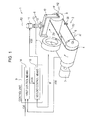
- Fig. 1 illustrates a tire test device 2 (running test device) provided with a belt meandering preventing device 1 according to an embodiment.
- the tire test device 2 includes a driving drum 4 that is connected to a driving motor 3 so as to be rotatable in forward and reverse directions, a driven drum 5 provided at a distance from the driving drum 4 in a manner such that the axes of the driving drum 4 and the driven drum 5 are parallel to each other, and a belt 6 formed by an endless metal plate laid between the driving drum 4 and the driven drum 5.
- the belt 6 has two upper and lower flat surfaces 7U and 7D between the driving drum 4 and the driven drum 5.
- a tire T (rolling element) is in contact with a road surface (test road surface) provided on the upper flat surface 7U.
- the tire test device 2 is configured to evaluate the running characteristic of the tire T while the tire T is in contact with the road surface on the belt 6.
- upper and lower sides of the paper of Fig. 1 are defined as upper and lower sides of the tire test device 2.
- a left end side in a feeding direction of the belt 6 passing over the driving drum 4 toward the driven drum 5 is defined as the left side in the description of the tire test device 2 and the belt meandering preventing device 1
- a right end side is defined as the right side in the description of the tire test device 2 and the belt meandering preventing device 1.
- the feeding direction of the belt 6 from the driving drum 4 in Fig. 1 is referred to as a forward direction, and a direction opposite the forward direction is referred to as a reverse direction.
- the driving drum 4 has a cylindrical shape around which the belt 6 can be wound.
- the driving drum 4 is rotatable on a rotation shaft R1 extending in the right-left direction, and can be selectively rotated in the forward and reverse directions by the driving motor 3 connected to the rotation shaft R1 via a gear box (not shown).
- the driven drum 5 is provided at a distance from the driving drum 4 in the horizontal direction in a manner such that the axes of the drums are parallel to each other. Similarly to the driving drum 4, the driven drum 5 can freely rotate on a rotation shaft R2 extending in the right-left direction.
- the belt 6 is formed by an endless metal band plate, a crawler, or the like, and is wound around both the driving drum 4 and the driven drum 5.
- a surface of the belt 6 facing toward the outer periphery is formed of a material such as asphalt or concrete.
- the belt 6 has the upper flat surface 7U and the lower flat surface 7D between the driving drum 4 and the driven drum 5.
- the tire T to be tested is in contact with the upper flat surface 7U from above.
- a layer of snow, ice, or water may be provided on the surface of the belt 6 facing toward the outer periphery so that the surface facing toward the outer periphery is in placed in an environment similar to that for the actual road surface.
- the belt meandering preventing device 1 of the embodiment corrects meandering of the belt 6 by rocking the driven drum 5, of the driving drum 4 and the driven drum 5 provided in the tire test device 2, relative to the driving drum 4.
- the belt meandering preventing device 1 includes a drum rocking means 8 that rocks the driven drum 5 relative to the driving drum 4 on a rocking axis R3 extending in the up-down direction and changes the position of the belt 6 in accordance with the amount of rocking, and a control unit 9 that controls the drum rocking means 8.
- the drum rocking means 8 rocks the driven drum 5 on the axis (rocking axis) extending in the up-down direction, and includes a frame member 10 that supports the driven drum 5 from both ends, and a servomotor 11 that rocks the frame member 10.
- the frame member 10 has a substantially angular U-shape pointing downward, and the driven drum 5 is rotatably attached to lower ends thereof.
- the frame member 10 has a rocking shaft portion 12 projecting upward, and can be rotated on the rocking axis R3 extending in the up-down direction by the servomotor 11 provided at an upper end of the rocking shaft portion 12.
- a rocking-amount detecting means 13 is provided in a portion of the rocking shaft portion 12 in the up-down direction, and can detect the relative rotation angle on the rocking axis R3 between the servomotor 11 and the rocking shaft portion 12.
- the control unit 9 is formed by a computer or a sequencer, and includes a first control means 14 and a second control means 15.
- the first control means 14 controls the drum rocking means 8 so that the difference between an actual position of the belt 6 and a predetermined target position becomes zero.
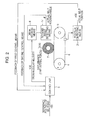
- the first control means 14 includes belt-position detecting means 21 that detect a measured position y(s) of the belt 6, a first control unit 31 that calculates the deviation amount between the actual position and the target position of the belt 6, and a PID control means 17 that calculates a target amount of rocking from the deviation amount between the actual position and the target position of the belt 6 detected by the first control unit 31 and outputs the calculated target amount of rocking to the drum rocking means 8.
- the belt-position detecting means 21 are provided at the left and right ends of the lower flat surface 8 of the belt 6, respectively, and at a predetermined distance from the flat surface 8.
- the belt-position detecting means 21 are formed by optical sensors that detect the right and left ends of the belt 6 by light transmission, and measure, from the change in amount of transmitted light, how much the ends of the belt 6 move in the right-left direction.
- the actual position y(s) of the belt 6 detected by the belt-position detecting means 21 is output to the first control means 14 in the control unit 9.
- the belt-position detecting means 21 are attached to positions on the lower side of the lower flat surface 7D of the belt 6 and close to the driven drum 5, and can detect, in a short time, the change in position of the belt 6 made when the driven drum 5 rocks.
- the actual position y(s) of the belt 6 detected by the belt-position detecting means 21 and a target position r(s) of the belt 6 are input to the first control unit 31.
- the target position r(s) of the belt 6 is a reference position of the belt 6 in a state in which the belt 6 does not meander, and is given to the first control unit 31 beforehand.
- the first control unit 31 calculates a deviation amount e(s) of the belt 6 by subtracting the target position r(s) of the belt 6 from the detected actual position y(s) of the belt 6 (difference between the detected position and the target position of the belt).
- the calculated deviation amount e(s) of the belt 6 is output to the PID control means 17.
- the PID control means 17 calculates a target amount of rocking u1 (s) of the drum rocking means 8 from the deviation amount e(s) of the belt 6. More specifically, the PID control means 17 accumulates the deviation amounts e(s) of the belt 6 input at a predetermined sampling period, and calculates the target amount of rocking u1 (s) of the drum rocking means 8 on the basis of a proportional gain, an integral gain, and a derivative gain obtained from the accumulated deviation amounts e(s). In this embodiment, a rocking angular velocity is used as the target amount of rocking u1 (s).
- the rocking angular velocity u1 (s) calculated by the PID control means 17 is output to the second control means 15.
- the driven drum 5 is rocked via the rocking shaft portion 12 driven by the servomotor 11 in a direction to remove deviation of the belt 6.
- a fixed time is required before the belt 6 influenced by the rock of the driven drum 5 reaches a position where the belt-position detecting means 21 is provided and the belt-position detecting means 21 evaluates the influence of rock of the driven drum 5.
- this time changes according to the positional relationship between the belt-position detecting means 21 and the drum rocking means 8, if the time is long, a time in which the belt 6 makes about one rotation is required.
- the belt 6 has a time constant considerably greater than that of the servomotor 11 or a hydraulic cylinder that is generally used for tilting the drum. Depending on the control period, the influence of response delay remains in the next control period, and this may result in insufficient control over the position of the belt 6. Accordingly, the belt meandering preventing device 1 of the present invention includes the second control means 15 as well as the above-described first control means 14.
- the second control means 15 detects the amount of rocking of the driven drum 5, and controls the drum rocking means 8 so that the detected drum amount of rocking becomes the target amount of rocking.
- the second control means 15 includes the rocking-amount detecting means 13 that detects an actual amount of rocking of the driven drum 5 rocked by the drum rocking means 8, and a second control unit 32 that controls the drum rocking means 8 so that the amount of rocking of the driven drum 5 detected by the rocking-amount detecting means 13 becomes the target amount of rocking.
- a rocking angular velocity ⁇ ' of the driven drum 5 is used as the amount of rocking.
- the rocking-amount detecting means 13 is provided in a portion of the rocking shaft portion 16 in the up-down direction.
- the rocking-amount detecting means 13 is formed by an encoder that measures the rotational displacement amount of the servomotor 11, and detects an actual rocking angle ⁇ of the driven drum 5 from the rocking angle of the servomotor 11.
- the actual rocking angle ⁇ of the driven drum 5 detected by the rocking-amount detecting means 13 is output to the second control unit 32.
- the second control unit 32 feeds back and inputs the actual rocking angle ⁇ of the driven drum 5 detected by the rocking-amount detecting means 13 to an input side of the drum rocking means 8. More specifically, the second control unit 32 calculates a rocking angular velocity ⁇ ' of the driven drum 5 from the actual rocking angle ⁇ input from the rocking-amount detecting means 13. Further, the rocking angular velocity u1 (s) calculated by the first control means 14 is also input to the second control unit 32. The second control unit 32 calculates the rocking angular velocity u(s) on the basis of the rocking angular velocity u1 (s) and the rocking angular velocity ⁇ '. The second control unit 32 outputs the calculated rocking angular velocity u(s) to the servomotor 11 of the drum rocking means 8, thereby correcting deviation of the belt 6.
- control unit 9 that is, a belt meandering preventing method for a running test device according to the embodiment.
- the belt meandering preventing method for the running test device rocks the driven drum 5 (the other drum) by using the drum rocking means 8, detects a rocking angle ⁇ (amount of rocking) of the driven drum 5, and controls the drum rocking means 8 so that the rocking angle ⁇ becomes the target amount of rocking.
- the driving motor 3 is driven to rotate the driving drum 4.
- the belt 6 laid between the driving drum 4 and the driven drum 5 also rotates.
- the tire running test is performed.
- the position of the belt 6 is adjusted to be r(s).
- tire lateral force and other disturbances are applied to the belt 6, and these cause meandering and deviation.
- the belt 6 deviates from a target position r(s) to an actual position y(s).
- the actual position y(s) of the belt 6 is detected by the belt-position detecting means 21.
- the detected actual position y(s) of the belt 6 is fed back to the input side of the first control unit 31 in the first control means 14 so as to be output to the first control unit 31.
- the target position r(s) of the belt 6 is input as an initial setting (given beforehand) to the first control unit 31.
- the first control unit 31 obtains a difference of the actual position y(s) of the belt 6 input from the belt-position detecting means 21 from the target position r(s) of the belt 6, and thereby calculates a deviation amount e(s) of the belt 6.
- the calculated deviation amount e(s) of the belt 6 is output to the PID control means 17 in the first control means 14.
- the PID control means 17 calculates a target rocking angular velocity u1 (s) of the drum rocking means 8 on the basis of the input deviation amount e(s) of the belt 6. A manner in which the deviation amount e(s) of the belt 6 changes is accumulated in the PID control means 17.
- the PID control means 17 determines gains (proportional gain, integral gain, and derivative gain) on the basis of the accumulated manner of change in deviation amount e(s) of the belt 6, and calculates the rocking angular velocity u1 (s) on the basis of the gains.
- the calculated rocking angular velocity u1 (s) is output to the second control unit 32 in the second control means 15.
- the driven drum 5 is turned in a direction to remove deviation of the belt 6 via the rocking shaft portion 12 driven by the servomotor 11.
- the time constant is considerably greater when the running position of the belt 6 is moved to the predetermined position than when the servomotor 11 is rocked at a predetermined rocking angular velocity. That is, even when the driven drum 5 is rocked, at least a half rotation to one rotation is required before the rock affects the entire belt 6. For this reason, it is difficult for the actual position of the belt 6 to reach the target value of the belt 6 in the above-described sampling period.
- the actual amount of rocking (rocking angular velocity) of the driven drum 5 is fed back to the input side of the drum rocking means 8, and the second control means 15 controls the drum rocking means 8 so that the rocking angular velocity of the driven drum 5 becomes the target rocking angular velocity.
- the second control means 15 performs control as follows. First, the encoder (rocking-amount detecting means 13) provided on the rocking shaft portion 16 of the frame member 12 measures and outputs a rotational displacement amount of the servomotor 11 to the second control unit 32. The second control unit 32 calculates an actual rocking angular velocity ⁇ ' of the driven drum 5 from the rotational displacement amount. Further, the second control unit 32 subtracts the actual rocking angular velocity ⁇ ' of the driven drum 5 from the rocking angular velocity ul (s) input from the first control unit 31 in the first control means 14, thereby calculating a rocking angular velocity u(s). Then, the second control unit 32 outputs the calculated rocking angular velocity u(s) to the drum rocking means 8. That is, the second control unit 32 controls the drum rocking means 8 so that the driven drum 5 rocks at the rocking angular velocity u(s).
- a tire test device 2 used in the example and the comparative example has a structure in which a tire T (outer diameter: 120 mm ⁇ , tire width: 50 mm) is in contact with an upper flat surface 7U of a belt 6 (belt width: 100 mm, belt length: 977 mm, belt thickness: 0.1 mm) laid between a driving drum 4 (outer diameter: 120 mm ⁇ , drum width 200 mm) and a driven drum 5 (outer diameter 120 mm ⁇ , drum width 200 mm) that are arranged in parallel.
- a belt meandering preventing device 1 includes a servomotor 11 that rocks the driven drum 5 on an axis extending in the up-down direction, and can rock the driven drum 5 via a frame member 10 by the servomotor 11.
- a light-transmissive sensor for detecting the position of the belt 6 at a sampling period of 15 Hz (6.7 ms) is attached as a belt-position detecting means 20 to a control unit 9 in the belt meandering preventing device 1.
- the comparison of the experimental example and the comparative example shows that the position of the belt 6 is quickly corrected and meandering and vibration of the belt 6 are reliably prevented by providing the second control means 15, which controls the drum rocking means 9 so that the amount of rocking of the driven drum 5 actually rocked by the drum rocking means 9 becomes the target amount of rocking in addition to the first control means 14 that controls the drum rocking means 9 so that the position of the belt 6 detected by the belt-position detecting means 20 becomes the target position.
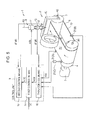
- a second embodiment of the present invention illustrated in Figs. 5 and 6 structures of a tire test device 2 and a drum rocking means 8 are similar to those adopted in the first embodiment.
- This embodiment is different from the first embodiment in the configuration of a control unit 9 and control performed by the control unit 9.
- the control unit 9 is formed by a computer or a sequencer, and includes a first control means 14, a second control means 15, and a third control means 16.
- the first control means 14 controls the drum rocking means 8 so that the difference between an actual position of a belt 6 and a predetermined target position becomes zero.
- the first control means 14 includes a first control unit 31 that calculates a deviation amount e(s) of a detected position rm(s) of the belt 6 from a target position r(s) input beforehand (difference between the detected position and the target position of the belt), and a PID control means 17 that controls the drum rocking means 8 on the basis of the deviation amount e(s).
- the position of the belt 6 that does not meander is given as the target position r(s) to the first control unit 31 beforehand, and the deviation amount e(s) is calculated by subtracting the target position r(s) from the detected position rm(s) of the belt 6 calculated by the third control means 16.
- the calculated deviation amount e(s) of the belt 6 is output to the PID control means 17.
- the PID control means 17 calculates a target amount of rocking u1 (s) on the basis of the deviation amount e(s) of the belt 6 input from the first control unit 31, and outputs this amount of rocking u1 (s) to the second control means 15.
- a rocking angular velocity is used as the amount of rocking u1 (s).
- the second control means 15 includes a rocking-amount detecting means 13 that detects an actual amount of rocking of the driven drum 5 rocked by the drum rocking means 8, and a second control unit 32 that controls the drum rocking means 8 so that the amount of rocking of the drum detected by the rocking-amount detecting means 13 becomes the target amount of rocking.
- the rocking-amount detecting means 13 is formed by an encoder that measures the rocking angle of a servomotor 11, and detects an actual rocking angle ⁇ of the driven drum 5 from the rocking angle of the servomotor 11.
- the actual rocking angle ⁇ of the driven drum 5 detected by the rocking-amount detecting means 13 is output to the second control unit 32.
- the second control unit 32 feeds back and inputs the actual rocking angle ⁇ of the driven drum 5 detected by the rocking-amount detecting means 13 to an input side of the drum rocking means 8.
- the rocking angular velocity u1 (s) calculated by the first control unit 31 in the first control means 14 is input to the second control unit 32, and the second control unit 32 calculates the amount of rocking, more specifically, a rocking angular velocity u(s) on the basis of the rocking angular velocity u1 (s) and the rocking angle ⁇ of the driven drum 5 detected by the rocking-amount detecting means 13.
- the second control unit 32 outputs the calculated rocking angular velocity u(s) to the servomotor 11 of the drum rocking means 8, thereby correcting deviation of the belt 6 in a short time.
- the servomotor 11 rotates on the basis of the rocking angular velocity u1 (s) calculated by the first control unit 31 and the rocking angular velocity u(s) calculated by the second control unit, and the driven drum 5 rotates in a direction to remove the deviation amount e(s) of the belt 6.
- a fixed time is required before the belt 6 influenced by the rock of the driven drum 5 reaches a position where a below-described belt-position detecting means 21 is provided and the belt-position detecting means 21 evaluates the influence of rock of the driven drum 5.
- this time changes according to the positional relationship between the belt-position detecting means 21 and the drum rocking means 8, if the time is long, a time in which the belt 6 makes about one rotation is required. That is, the belt 6 has a time constant considerably greater than that of the servomotor 11 or a hydraulic cylinder that is generally used for tilting the drum. Depending on the control period, the influence of this response delay may remain in the next control period and this may result in insufficient control over the position of the belt 6.
- the belt meandering preventing device 1 of the present invention includes the third control means 16 that calculates the detected position of the belt 6 from which the response delay and response in the opposite direction are removed, in addition to the first control means 14 and the second control means 15 described above.
- the third control means 16 includes the belt-position detecting means 21 that detects a measured position y(s) of the belt 6, and a third control unit 33 that finds an estimated position ym(s) of the belt 6 by inputting the amount of rocking ⁇ of the drum detected by the second control means 15 to a belt response model and calculates a detected position rm(s) of the belt 6 on the basis of a difference ⁇ y(s) between the estimated position ym(s) and the measured position y(s) of the belt 6 and an integral value ⁇ obtained by integrating the amount of rocking ⁇ of the drum.
- the belt-position detecting means 21 can actually measure the position of an end of the belt 6 wound around the driving drum 4, and in this embodiment, is provided at a fixed distance above from the belt 6 near the boundary between an upper flat surface 7U and the driving drum 4.
- the belt-position detecting means 21 can detect the measured position y(s) of the belt 6 by applying infrared rays onto the belt 6 and receiving reflected light.
- the measured position y(s) of the belt 6 detected by the belt-position detecting means 21 is output to the third control unit in the control unit 9.
- the rocking angle ⁇ of the driven drum 5 detected by the rocking-amount detecting means 13 in the second control means 15 and the measured position y(s) of the belt 6 detected by the belt-position detecting means 21 are input to the third control unit 33.
- the third control unit 33 finds an estimated position ym(s) of the belt 6 by inputting the amount of rocking ⁇ of the driven drum 5 to a belt response model, and calculates a deviation amount ⁇ y (s) of the belt 6 on the basis of the estimated position ym(s) and the measured position y(s) of the belt 6. Further, the third control unit 33 multiplies an integral value ⁇ obtained by integrating the input rocking angle ⁇ of the belt 6 by a predetermined constant ⁇ .
- the calculated detected position rm(s) of the belt 6 is output to the first control unit 31, and is used in the first control means 14 so as to calculate a target rocking angular velocity u1 (s) on the basis of the detected position rm(s) of the belt 6.
- the belt response model can reproduce the actual belt behavior caused when the driven drum 5 is rocked, and is formed by a discrete model or a dynamic model based on actual data on the measured belt behavior.
- control unit 9 that is, a belt meandering preventing method for a running test device according to the present invention.
- the driven drum 5 (the other drum) is rocked by the drum rocking means 8, a rocking angle ⁇ (amount of rocking) of the driven drum 5 is detected, and the drum rocking means 8 is first controlled so that the rocking angle ⁇ becomes the target amount of rocking.
- an estimated position ym(s) of the belt 6 is found by inputting the rocking angle ⁇ to a belt response model, a difference ⁇ y (s) between the estimated position ym(s) and the actually detected measured position y(s) of the belt 6 is found, a detected position rm(s) of the belt 6 is found on the basis of an integral value ⁇ of the rocking angle ⁇ and the difference ⁇ y (s), and the drum rocking means 8 is controlled so that the difference between the detected position rm(s) of the belt 6 and the predetermined target position r(s) becomes zero. More specifically, this belt meandering preventing method is performed as follows.
- the driving motor 3 is driven to rotate the driving drum 4.
- the belt 6 laid between the driving drum 4 and the driven drum 5 also rotates.
- the running test for the tire T is conducted by bringing the tire T into contact with the upper flat surface 7U of the belt 6.
- the position of the belt 6 is adjusted to be at the target position r(s).
- tire lateral force and other disturbances are applied to the belt 6, and these cause meandering and deviation.
- the actual belt 6 deviates from the target position r(s) to the measured position y(s).
- rocking angular velocity u1 (s) calculated by the first control means 14 is input to the drum rocking means 8 and the servomotor 11 operates in the drum rocking means 8 so that the amount of rocking (rocking angular velocity) becomes u1 (s), the driven drum 5 rotates via the frame member 10 in a direction to remove deviation of the belt 6.
- a certain time constant exists even when the servomotor 11 is rocked at a predetermined angular velocity.
- the drum rocking means 8 is controlled in the above-described sampling period so as to obtain the rocking angular velocity u1 (s), it is difficult for the actual rocking angle ⁇ (amount of rocking) of the driven drum 5 to reach the target value.
- the actual rocking angle ⁇ of the driven drum 5 is detected by the rocking-amount detecting means 13, and the detected rocking angle ⁇ is fed back to the input side of the second control unit, whereby the drum rocking means 8 is controlled so that the driven drum 5 is rocked at the rocking angular velocity u(s).
- the driven drum 5 is rocked to the target amount of rocking (rocking angle or rocking angular velocity) and meandering and vibration of the belt 6 due to the delay of the drum rocking means 8 can be prevented.
- the target amount of rocking rocking angle or rocking angular velocity
- the influence of a transient response and the influence of response delay occur in the belt 6 to which the rock of the driven drum 5 is transmitted, as described above.
- the drum rocking means 8 is controlled by feeding back the measured position y(s) of the belt 6 detected by the belt-position detecting means 21 to the first control means 14 unchanged, the belt 6 causes overshooting and oscillation, and this makes sufficient control impossible.
- the rocking angle ⁇ input to the second control unit 32 in the second control means 15 is also input to the third control unit 33, and the estimated position ym(s) of the belt 6 is found by inputting the input rocking angle ⁇ to the belt response model.
- the difference ⁇ y (s) between the estimated position ym(s) of the belt 6 calculated using the belt response model and the measured position y(s) of the belt 6 is calculated, and this difference ⁇ y (s) is treated as the deviation amount of the belt 6.
- the integral value ⁇ is obtained by integrating the input rocking angle ⁇ of the driven drum 5.
- This integral value ⁇ represents the tilting angle of the driven drum 5 at the time of detection.
- the detected position rm(s) of the belt 6 thus found is input to the above-described first control means 14, and the first control unit controls the drum rocking means 8 so that the difference between the detected position rm(s) of the belt 6 and the predetermined target position r(s) becomes zero.
- a tire test device 2 used in the experimental example and the comparative example has a structure in which a tire T (outer diameter: 120 mm ⁇ , tire width: 50 mm) is in contact with an upper flat surface 7U of a belt 6 (belt width: 100 mm, belt length: 977 mm, belt thickness: 0.1 mm) laid between a driving drum 4 (outer diameter: 120 mm ⁇ , drum width 200 mm) and a driven drum 5 (outer diameter 120 mm ⁇ , drum width 200 mm) that are arranged in parallel.
- a belt meandering preventing device 1 includes a servomotor 11 that rocks the driven drum 5 on an axis extending in the up-down direction, and can rock the driven drum 5 via a frame member 10 by the servomotor 11.
- a light-reflective sensor C for detecting the position of the belt 6 at a sampling period of 15 Hz (6.7 ms) is attached as a belt-position detecting means 20 to the belt meandering preventing device 1.
- a light-transmissive sensor (sensor A) is provided on the upper flat surface 7U near the tire T and a light-transmissive sensor (sensor B) is provided on a lower flat surface 7D near the driving drum 4.
- a calculation method for a belt response model provided in a third control unit 33 of the belt meandering preventing device 1 of the experimental example will be described below by taking a model that compensates only inverse response as an example.
- Fig. 8 shows measured positions of the belt 6 detected by the light-reflective sensor and the light-transmissive sensors described above when the belt 6 is rotated in a state in which the driven drum 5 is tilted 0.25° beforehand.
- the experimental example uses a belt response model in which the change in deviation amount of the belt 6 with respect to the rotation angle of the driven drum 5 is expressed in an IIR discrete expression given by Expression (1).
- the change in position of the belt 6 in the result of the example is smaller than in the result of the comparative example, and it is therefore known that overshooting of the belt 6 is suppressed.
- the example that simulates the behavior of the belt 6 in the direction opposite the target position is given as the belt response model.
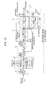
- a belt response model that can simulate the dead time (delay) of the belt response in addition to the behavior of inverse response shown in Fig. 9 may be used.
- a belt response model that reflects only the dead time can be used.
- the present invention is not limited to the above embodiments, and the shapes, structures, materials, combinations, etc. of the members can be appropriately changed without departing from the essence of the present invention.
- the servomotor 11 is used in the drum rocking means 8.
- the drum rocking means 8 is not limited only to the servomotor 11.
- arms extending in the front-rear direction can be provided on either sides of the driven drum 5, and the driven drum 5 can be rocked by expanding and contracting the arms in the front-rear direction by a hydraulic cylinder or the like.
- the drum rocking means 8 rocks the driven drum 5 on the rocking shaft portion 12.
- the rocking direction of the driven drum 5 is not limited to the direction around the rocking axis R3.
- the driven drum 5 can be rocked on an axis extending in the front-rear direction by moving any end of the driven drum 5 in the up-down direction.
- the drum rocking means 8 rocks the driven drum 5 relative to the driving drum 4.
- the drum rocking means 8 may rock the driving drum 4 relative to the driven drum 5.
- the second control means 15 feeds back the rocking angular velocity of the driven drum 5 measured by the encoder to the input side of the drum rocking means 8.
- the second control means 15 can feed back the rocking angle or the rocking angular velocity of the driven drum 5 to the input side of the drum rocking means 8.
- the reflective infrared sensor provided on the upper flat surface 7U of the belt 6 is used in the belt-position detecting means 21.
- the sensor used in the belt-position detecting means 21 does not always need to be a reflective sensor or an infrared sensor.
- the belt-position detecting means 21 may be set at any position where the belt-position detecting means 21 can detect the position of the end of the belt 6.
- a transmissive light sensor may be provided on the lower flat surface 7D, or may be provided above the driven drum 5.
Landscapes
- Engineering & Computer Science (AREA)
- Physics & Mathematics (AREA)
- General Physics & Mathematics (AREA)
- Human Computer Interaction (AREA)
- Manufacturing & Machinery (AREA)
- Automation & Control Theory (AREA)
- Control Of Conveyors (AREA)
- Testing Of Devices, Machine Parts, Or Other Structures Thereof (AREA)
- Devices For Conveying Motion By Means Of Endless Flexible Members (AREA)
Abstract
Description
- The present invention relates to a belt meandering preventing device and a belt meandering preventing method for a running test device.
- A running test device that evaluates the running characteristic of a rolling element, a tire or a vehicle, by using a metal belt is known. The running test device includes a driven drum and a driving drum, and an endless belt is laid between the driven drum and the driving drum. In the running test device, an upper flat surface of the belt serves as a test road surface. By running the belt while the rolling element is in contact with the test road surface, the running characteristic of the rolling body is evaluated.
- While the driven drum and the driving drum are formed to have a truly round cross section, these drums are microscopically not truly round. Moreover, it is difficult to arrange two drums in strictly parallel, and the belt has fine irregularities. For this reason, the belt laid between the two drums meanders or deviates inevitably.
- Accordingly, for example,
Patent Documents 1 to 3 disclose devices that detect the position of an end of a belt and that correct meandering by tilting a driven drum or adjusting the tension on the basis of the detected belt position. - [Patent Document 1] Japanese Unexamined Patent Application Publication No.
2004-359379 - [Patent Document 2] Japanese Unexamined Patent Application Publication No.
2005-351302 - [Patent Document 3] Japanese Unexamined Patent Application Publication No.
2005-326638 - For example, even when the drum is tilted, the locus of the belt rotating on the drums changes only when the belt makes at least about one rotation. Hence, the locus change of the belt has an even higher time constant than a servomotor or hydraulic cylinder that is generally used for tilting the drum. For this reason, in the devices of
Patent Documents 1 to 3, even when the driven drum is rocked, the belt does not immediately move to the target position. In this case, the influence of response delay may remain in the nest control period, and result in insufficient control over the belt position. - In addition, it is known, from previous findings, that, immediately after the drum is rocked, a transient phenomenon in which the belt responds in a direction opposite a direction toward the target position occurs in the belt. If such a transient phenomenon occurs, an unnecessary displacement amount resulting from the transient phenomenon is added to the detected deviation amount of the belt position, and the control may cause meandering and oscillation of the belt position.
- The present invention has been made in view of the above-described problems, and an object of the invention is to provide a belt meandering preventing device and meandering preventing method for a running test device that can quickly correct a belt to a target position and can reliably prevent meandering and vibration of the belt.
- The present inventors thought that, if the time constant of a belt was considerably higher than the time constant of a drum rocking means, it should be better to further improve the responsiveness of the drum rocking means having the low time constant. Further, the present inventors found that the belt could be quickly corrected to the target position by controlling the drum rocking means on the basis of the amount of rocking of the drum, and accomplished the present invention.
- According to a first aspect of the present invention, there is provided a belt meandering preventing device for a running test device, which is provided in the running test device that evaluates a running characteristic of a rolling element while the rolling element is in contact with a belt laid between a pair of drums, and which corrects meandering of the belt by drum rocking means that rocks, relative to one of the drums, the other drum and that changes a position of the belt in accordance with an amount of rocking of the other drum. The belt meandering preventing device includes first control means that detects the position of the belt and controls the drum rocking means so that a difference between the detected position of the belt and a predetermined target position becomes zero; and second control means that detects the amount of rocking of the other drum rocked by the drum rocking means and controls the drum rocking means so that the detected amount of rocking of the drum becomes a target amount of rocking.
- The belt meandering preventing device for the test running device according to the present invention includes not only the first control means that controls the drum rocking means on the basis of the detected position and the target position of the drum, but also the second control means that controls the drum rocking means on the basis of the detected amount of rocking and the target amount of rocking of the drum. Since this structure further improves the responsiveness of the drum rocking means having a low time constant, the belt can be quickly corrected to the target position, and meandering and vibration of the belt can be prevented reliably.
- More specifically, the second control means detects the amount of rocking of the other drum, calculates a difference between the detected amount of rocking and the target amount of rocking, and feeds back the difference in the amount of rocking to an input side of the drum rocking means. Further, the first control means calculates the difference between the detected position and the target position of the belt, and feeds back the difference to the input side of the drum rocking means.
- The present inventors thought that, if the response of the belt delayed or the belt responded in a direction opposite the target position, an accurate detected position of the drum could be obtained by setting a belt response model that simulates such response of the belt and grasping a deviation state of the belt on the basis of the belt response mode. Then, the present inventors found that the belt could be quickly corrected to the target position by controlling the drum rocking means using the detected position of the belt calculated by inputting the amount of rocking of the drum to the belt response model.
- That is, more preferably, the belt meandering preventing device further includes third control means that calculates a difference between an estimated position of the belt obtained by inputting the amount of rocking of the drum detected by the second control means to a belt response model and a measured position of the belt detected by belt-position detecting means, calculates an integral value obtained by integrating the amount of rocking of the drum, and calculates a detected position of the belt on the basis of the difference and the integral value.
- According to this structure, an accurate detected position of the belt is found from the deviation state of the belt grasped by the third control means on the basis of the belt response model. The first control means controls the drum rocking means on the basis of the accurate detected position of the belt and the target position of the drum. As a result, the belt can be more quickly corrected to the target position, and meandering and vibration of the belt can be more reliably prevented.
- More specifically, the belt response model simulates a response behavior of the belt in a direction opposite the target position and/or response delay of the belt.
- More specifically, the first control means includes PID control means that calculates a target amount of rocking of the drum rocking means from the difference between the detected position and the target position of the belt. Further, the amount of rocking is a rocking angle or a rocking angular velocity of the other drum.
- According to a second aspect of the present invention, there is provided a belt meandering preventing method for a running test device, which corrects meandering of a belt laid between a pair of drums by drum rocking means that is provided in the running test device for evaluating a running characteristic of a rolling element while the rolling element is in contact with the belt and that rocks, relative to one of the drums, the other drum, and that changes a position of the belt in accordance with an amount of rocking of the other drum. The belt meandering preventing method detects the position of the belt and controls the drum rocking means so that a difference between the detected position and a predetermined target position of the belt becomes zero, and detects the amount of rocking of the other drum rocked by the drum rocking means and controls the drum rocking means so that the detected amount of rocking of the drum becomes a target amount of rocking.
- Preferably, the method finds a difference between an estimated position of the belt found by inputting the amount of rocking of the drum to a belt response model and a measured position of the drum actually detected, and finds the detected position of the belt on the basis of an integral value of the amount of rocking of the drum and the difference.
- The belt meandering preventing device and meandering preventing method of the present invention can quickly correct the belt to the target position and thereby reliably prevent meandering and vibration of the belt.
-
- [
Fig. 1] Fig. 1 is a perspective view of a tire test device according to an embodiment. - [
Fig. 2] Fig. 2 is a block diagram showing the flow of signals in a meandering preventing device. - [
Fig. 3] Fig. 3 is a block diagram showing the flow of signals in a control unit. - [
Fig. 4] Fig. 4(a) shows the change in a belt position in a comparative example, andFig. 4(b) shows the displacement of a belt position in an example. - [
Fig. 5] Fig. 5 is a perspective view of a tire test device according to a second embodiment. - [
Fig. 6] Fig. 6 is a block diagram showing the flow of signals in a belt meandering preventing device. - [
Fig. 7] Fig. 7 is a block diagram showing the flow of signals in a control unit. - [
Fig. 8] Fig. 8 shows the change in deviation amount of a belt with respect to the rotating angle of a driven drum. - [
Fig. 9] Fig. 9(a) shows the change in belt position when control is performed by a belt meandering preventing device of the example, andFig. 9(b) shows the change in belt position when control is performed by a belt meandering preventing device of the comparative example. - [
Fig. 10] Fig. 10 is a block diagram showing the flow of signals in a control unit using a belt response model that simulates the delay in belt response in addition to the inverse response behavior. -
- 1
- belt meandering preventing device
- 2
- tire test device
- 3
- driving motor
- 4
- driving drum
- 5
- driven drum
- 6
- belt
- 7D
- lower flat surface
- 7U
- upper flat surface
- 8
- drum rocking means
- 9
- control unit
- 10
- frame member
- 11
- servomotor
- 12
- rocking shaft portion
- 13
- rocking-amount detecting means
- 14
- first control means
- 15
- second control means
- 16
- third control means
- 17
- PID control means
- 21
- belt-position detecting means
- 31
- first control unit
- 32
- second control unit
- 33
- third control unit
- R1, R2
- rotation shaft
- R3
- rocking axis
- T
- tire
- A meandering preventing device and meandering preventing method for a running test device according to an embodiment of the present invention will be described in detail below with reference to the drawings.
-
Fig. 1 illustrates a tire test device 2 (running test device) provided with a belt meandering preventingdevice 1 according to an embodiment. - The
tire test device 2 includes a drivingdrum 4 that is connected to a driving motor 3 so as to be rotatable in forward and reverse directions, a drivendrum 5 provided at a distance from the drivingdrum 4 in a manner such that the axes of the drivingdrum 4 and the drivendrum 5 are parallel to each other, and abelt 6 formed by an endless metal plate laid between the drivingdrum 4 and the drivendrum 5. Thebelt 6 has two upper and lowerflat surfaces drum 4 and the drivendrum 5. A tire T (rolling element) is in contact with a road surface (test road surface) provided on the upperflat surface 7U. Thetire test device 2 is configured to evaluate the running characteristic of the tire T while the tire T is in contact with the road surface on thebelt 6. - In the following description, upper and lower sides of the paper of
Fig. 1 are defined as upper and lower sides of thetire test device 2. Further, a left end side in a feeding direction of thebelt 6 passing over the drivingdrum 4 toward the drivendrum 5 is defined as the left side in the description of thetire test device 2 and the belt meandering preventingdevice 1, and a right end side is defined as the right side in the description of thetire test device 2 and the belt meandering preventingdevice 1. The feeding direction of thebelt 6 from the drivingdrum 4 inFig. 1 is referred to as a forward direction, and a direction opposite the forward direction is referred to as a reverse direction. - The driving
drum 4 has a cylindrical shape around which thebelt 6 can be wound. The drivingdrum 4 is rotatable on a rotation shaft R1 extending in the right-left direction, and can be selectively rotated in the forward and reverse directions by the driving motor 3 connected to the rotation shaft R1 via a gear box (not shown). - The driven
drum 5 is provided at a distance from the drivingdrum 4 in the horizontal direction in a manner such that the axes of the drums are parallel to each other. Similarly to the drivingdrum 4, the drivendrum 5 can freely rotate on a rotation shaft R2 extending in the right-left direction. - The
belt 6 is formed by an endless metal band plate, a crawler, or the like, and is wound around both the drivingdrum 4 and the drivendrum 5. A surface of thebelt 6 facing toward the outer periphery is formed of a material such as asphalt or concrete. Thebelt 6 has the upperflat surface 7U and the lowerflat surface 7D between the drivingdrum 4 and the drivendrum 5. In this embodiment, the tire T to be tested is in contact with the upperflat surface 7U from above. A layer of snow, ice, or water may be provided on the surface of thebelt 6 facing toward the outer periphery so that the surface facing toward the outer periphery is in placed in an environment similar to that for the actual road surface. - As illustrated in
Figs. 1 and2 , the belt meandering preventingdevice 1 of the embodiment corrects meandering of thebelt 6 by rocking the drivendrum 5, of the drivingdrum 4 and the drivendrum 5 provided in thetire test device 2, relative to the drivingdrum 4. The belt meandering preventingdevice 1 includes a drum rocking means 8 that rocks the drivendrum 5 relative to the drivingdrum 4 on a rocking axis R3 extending in the up-down direction and changes the position of thebelt 6 in accordance with the amount of rocking, and acontrol unit 9 that controls the drum rocking means 8. - The drum rocking means 8 rocks the driven
drum 5 on the axis (rocking axis) extending in the up-down direction, and includes aframe member 10 that supports the drivendrum 5 from both ends, and aservomotor 11 that rocks theframe member 10. - The
frame member 10 has a substantially angular U-shape pointing downward, and the drivendrum 5 is rotatably attached to lower ends thereof. Theframe member 10 has a rockingshaft portion 12 projecting upward, and can be rotated on the rocking axis R3 extending in the up-down direction by theservomotor 11 provided at an upper end of the rockingshaft portion 12. A rocking-amount detecting means 13 is provided in a portion of the rockingshaft portion 12 in the up-down direction, and can detect the relative rotation angle on the rocking axis R3 between theservomotor 11 and the rockingshaft portion 12. - The
control unit 9 is formed by a computer or a sequencer, and includes a first control means 14 and a second control means 15. - The first control means 14 controls the drum rocking means 8 so that the difference between an actual position of the
belt 6 and a predetermined target position becomes zero. The first control means 14 includes belt-position detecting means 21 that detect a measured position y(s) of thebelt 6, afirst control unit 31 that calculates the deviation amount between the actual position and the target position of thebelt 6, and a PID control means 17 that calculates a target amount of rocking from the deviation amount between the actual position and the target position of thebelt 6 detected by thefirst control unit 31 and outputs the calculated target amount of rocking to the drum rocking means 8. - The belt-position detecting means 21 are provided at the left and right ends of the lower
flat surface 8 of thebelt 6, respectively, and at a predetermined distance from theflat surface 8. The belt-position detecting means 21 are formed by optical sensors that detect the right and left ends of thebelt 6 by light transmission, and measure, from the change in amount of transmitted light, how much the ends of thebelt 6 move in the right-left direction. The actual position y(s) of thebelt 6 detected by the belt-position detecting means 21 is output to the first control means 14 in thecontrol unit 9. In the embodiment, the belt-position detecting means 21 are attached to positions on the lower side of the lowerflat surface 7D of thebelt 6 and close to the drivendrum 5, and can detect, in a short time, the change in position of thebelt 6 made when the drivendrum 5 rocks. - The actual position y(s) of the
belt 6 detected by the belt-position detecting means 21 and a target position r(s) of thebelt 6 are input to thefirst control unit 31. The target position r(s) of thebelt 6 is a reference position of thebelt 6 in a state in which thebelt 6 does not meander, and is given to thefirst control unit 31 beforehand. Thefirst control unit 31 calculates a deviation amount e(s) of thebelt 6 by subtracting the target position r(s) of thebelt 6 from the detected actual position y(s) of the belt 6 (difference between the detected position and the target position of the belt). The calculated deviation amount e(s) of thebelt 6 is output to the PID control means 17. - The PID control means 17 calculates a target amount of rocking u1 (s) of the drum rocking means 8 from the deviation amount e(s) of the
belt 6. More specifically, the PID control means 17 accumulates the deviation amounts e(s) of thebelt 6 input at a predetermined sampling period, and calculates the target amount of rocking u1 (s) of the drum rocking means 8 on the basis of a proportional gain, an integral gain, and a derivative gain obtained from the accumulated deviation amounts e(s). In this embodiment, a rocking angular velocity is used as the target amount of rocking u1 (s). Although the range of the sampling period cannot be necessarily determined because the sampling period variously changes according to the sizes, operating conditions, and so on of thebelt 6 and the drivendrum 5, it is set at 10 to 200 ms, preferably, 10 to 50 ms. The rocking angular velocity u1 (s) calculated by the PID control means 17 is output to the second control means 15. - In the drum rocking means 8, the driven
drum 5 is rocked via the rockingshaft portion 12 driven by theservomotor 11 in a direction to remove deviation of thebelt 6. However, in actuality, even when the drivendrum 5 is rocked, a fixed time is required before thebelt 6 influenced by the rock of the drivendrum 5 reaches a position where the belt-position detecting means 21 is provided and the belt-position detecting means 21 evaluates the influence of rock of the drivendrum 5. Although this time changes according to the positional relationship between the belt-position detecting means 21 and the drum rocking means 8, if the time is long, a time in which thebelt 6 makes about one rotation is required. That is, thebelt 6 has a time constant considerably greater than that of theservomotor 11 or a hydraulic cylinder that is generally used for tilting the drum. Depending on the control period, the influence of response delay remains in the next control period, and this may result in insufficient control over the position of thebelt 6. Accordingly, the belt meandering preventingdevice 1 of the present invention includes the second control means 15 as well as the above-described first control means 14. - The second control means 15 detects the amount of rocking of the driven
drum 5, and controls the drum rocking means 8 so that the detected drum amount of rocking becomes the target amount of rocking. The second control means 15 includes the rocking-amount detecting means 13 that detects an actual amount of rocking of the drivendrum 5 rocked by the drum rocking means 8, and asecond control unit 32 that controls the drum rocking means 8 so that the amount of rocking of the drivendrum 5 detected by the rocking-amount detecting means 13 becomes the target amount of rocking. In this embodiment, a rocking angular velocity θ' of the drivendrum 5 is used as the amount of rocking. - The rocking-
amount detecting means 13 is provided in a portion of the rockingshaft portion 16 in the up-down direction. The rocking-amount detecting means 13 is formed by an encoder that measures the rotational displacement amount of theservomotor 11, and detects an actual rocking angle θ of the drivendrum 5 from the rocking angle of theservomotor 11. The actual rocking angle θ of the drivendrum 5 detected by the rocking-amount detecting means 13 is output to thesecond control unit 32. - The
second control unit 32 feeds back and inputs the actual rocking angle θ of the drivendrum 5 detected by the rocking-amount detecting means 13 to an input side of the drum rocking means 8. More specifically, thesecond control unit 32 calculates a rocking angular velocity θ' of the drivendrum 5 from the actual rocking angle θ input from the rocking-amount detecting means 13. Further, the rocking angular velocity u1 (s) calculated by the first control means 14 is also input to thesecond control unit 32. Thesecond control unit 32 calculates the rocking angular velocity u(s) on the basis of the rocking angular velocity u1 (s) and the rocking angular velocity θ'. Thesecond control unit 32 outputs the calculated rocking angular velocity u(s) to theservomotor 11 of the drum rocking means 8, thereby correcting deviation of thebelt 6. - Next, a description will be given of an operation performed by the
control unit 9, that is, a belt meandering preventing method for a running test device according to the embodiment. - The belt meandering preventing method for the running test device according to the embodiment rocks the driven drum 5 (the other drum) by using the drum rocking means 8, detects a rocking angle θ (amount of rocking) of the driven
drum 5, and controls the drum rocking means 8 so that the rocking angle θ becomes the target amount of rocking. - To conduct a tire running test with the
tire test device 2, first, the driving motor 3 is driven to rotate the drivingdrum 4. When the drivingdrum 4 rotates, thebelt 6 laid between the drivingdrum 4 and the drivendrum 5 also rotates. By bringing the tire T into contact with the upper flat surface of thebelt 6, the tire running test is performed. - In this case, the position of the
belt 6 is adjusted to be r(s). However, tire lateral force and other disturbances are applied to thebelt 6, and these cause meandering and deviation. As a result, thebelt 6 deviates from a target position r(s) to an actual position y(s). - In the belt meandering preventing method of the embodiment, first, the actual position y(s) of the
belt 6 is detected by the belt-position detecting means 21. The detected actual position y(s) of thebelt 6 is fed back to the input side of thefirst control unit 31 in the first control means 14 so as to be output to thefirst control unit 31. The target position r(s) of thebelt 6 is input as an initial setting (given beforehand) to thefirst control unit 31. Thefirst control unit 31 obtains a difference of the actual position y(s) of thebelt 6 input from the belt-position detecting means 21 from the target position r(s) of thebelt 6, and thereby calculates a deviation amount e(s) of thebelt 6. The calculated deviation amount e(s) of thebelt 6 is output to the PID control means 17 in the first control means 14. - The PID control means 17 calculates a target rocking angular velocity u1 (s) of the drum rocking means 8 on the basis of the input deviation amount e(s) of the
belt 6. A manner in which the deviation amount e(s) of thebelt 6 changes is accumulated in the PID control means 17. The PID control means 17 determines gains (proportional gain, integral gain, and derivative gain) on the basis of the accumulated manner of change in deviation amount e(s) of thebelt 6, and calculates the rocking angular velocity u1 (s) on the basis of the gains. The calculated rocking angular velocity u1 (s) is output to thesecond control unit 32 in the second control means 15. - In the drum rocking means 8, the driven
drum 5 is turned in a direction to remove deviation of thebelt 6 via the rockingshaft portion 12 driven by theservomotor 11. However, the time constant is considerably greater when the running position of thebelt 6 is moved to the predetermined position than when theservomotor 11 is rocked at a predetermined rocking angular velocity. That is, even when the drivendrum 5 is rocked, at least a half rotation to one rotation is required before the rock affects theentire belt 6. For this reason, it is difficult for the actual position of thebelt 6 to reach the target value of thebelt 6 in the above-described sampling period. Accordingly, in the meandering preventing method for thebelt 6 according to the embodiment, the actual amount of rocking (rocking angular velocity) of the drivendrum 5 is fed back to the input side of the drum rocking means 8, and the second control means 15 controls the drum rocking means 8 so that the rocking angular velocity of the drivendrum 5 becomes the target rocking angular velocity. - The second control means 15 performs control as follows. First, the encoder (rocking-amount detecting means 13) provided on the rocking
shaft portion 16 of theframe member 12 measures and outputs a rotational displacement amount of theservomotor 11 to thesecond control unit 32. Thesecond control unit 32 calculates an actual rocking angular velocity θ' of the drivendrum 5 from the rotational displacement amount. Further, thesecond control unit 32 subtracts the actual rocking angular velocity θ' of the drivendrum 5 from the rocking angular velocity ul (s) input from thefirst control unit 31 in the first control means 14, thereby calculating a rocking angular velocity u(s). Then, thesecond control unit 32 outputs the calculated rocking angular velocity u(s) to the drum rocking means 8. That is, thesecond control unit 32 controls the drum rocking means 8 so that the drivendrum 5 rocks at the rocking angular velocity u(s). - When the drum rocking means 8 is thus controlled by the second control means 15, it is possible to remove or reduce the influence of the time constant of the
belt 6 considerably greater than that of theservomotor 11 in the drum rocking means 8 and to quickly correct the belt to the target position. This reliably prevents meandering and vibration of thebelt 6. - Next, a description will be given of the belt meandering preventing
device 1 and the belt meandering preventing method of the first embodiment in conjunction with an experimental example corresponding to the first embodiment and a comparative example. - A
tire test device 2 used in the example and the comparative example has a structure in which a tire T (outer diameter: 120 mmφ, tire width: 50 mm) is in contact with an upperflat surface 7U of a belt 6 (belt width: 100 mm, belt length: 977 mm, belt thickness: 0.1 mm) laid between a driving drum 4 (outer diameter: 120 mmφ, drum width 200 mm) and a driven drum 5 (outer diameter 120 mmφ, drum width 200 mm) that are arranged in parallel. - A belt meandering preventing
device 1 includes aservomotor 11 that rocks the drivendrum 5 on an axis extending in the up-down direction, and can rock the drivendrum 5 via aframe member 10 by theservomotor 11. A light-transmissive sensor for detecting the position of thebelt 6 at a sampling period of 15 Hz (6.7 ms) is attached as a belt-position detecting means 20 to acontrol unit 9 in the belt meandering preventingdevice 1. - To clarify the differences of advantage, displacement of the position of the
belt 6 caused until 60 seconds elapsed from the start of control was measured in the example and the comparative example. Measurement of the position of thebelt 6 was started after the position of thebelt 6 at the start of control was intentionally deviated by 2 mm from a position where thebelt 6 passed without deviation.Fig. 4 shows the result of measurement. - As shown in
Fig. 4(a) , in the comparative example in which meandering was prevented only by the first control means 14 without using the second control means 15, the influence of the position of thebelt 6 at the start of control remained until 15 seconds elapsed from the start of control, and the position of thebelt 6 was displaced greatly. Further, even after 15 seconds elapsed from the start of control, a vibration of about ±0.3 mm was observed, and this vibration still remained. In contrast, as shown inFig. 4 (b) , in the experimental example in which meandering was prevented by using both the first control means 14 and the second control means 15, the influence of the position of thebelt 6 at the start of control disappeared when five seconds elapsed from the start of control, and meandering and deviation of thebelt 6 were made smaller in a shorter time than in the comparative example. Although a slight vibration of about ±0.1 mm was also observed after 15 seconds elapsed from the start of control, the amplitude thereof decreased, and vibration was suppressed reliably. - The comparison of the experimental example and the comparative example shows that the position of the
belt 6 is quickly corrected and meandering and vibration of thebelt 6 are reliably prevented by providing the second control means 15, which controls the drum rocking means 9 so that the amount of rocking of the drivendrum 5 actually rocked by the drum rocking means 9 becomes the target amount of rocking in addition to the first control means 14 that controls the drum rocking means 9 so that the position of thebelt 6 detected by the belt-position detecting means 20 becomes the target position. - In a second embodiment of the present invention illustrated in
Figs. 5 and6 , structures of atire test device 2 and a drum rocking means 8 are similar to those adopted in the first embodiment. This embodiment is different from the first embodiment in the configuration of acontrol unit 9 and control performed by thecontrol unit 9. - The
control unit 9 is formed by a computer or a sequencer, and includes a first control means 14, a second control means 15, and a third control means 16. - The first control means 14 controls the drum rocking means 8 so that the difference between an actual position of a
belt 6 and a predetermined target position becomes zero. The first control means 14 includes afirst control unit 31 that calculates a deviation amount e(s) of a detected position rm(s) of thebelt 6 from a target position r(s) input beforehand (difference between the detected position and the target position of the belt), and a PID control means 17 that controls the drum rocking means 8 on the basis of the deviation amount e(s). The position of thebelt 6 that does not meander is given as the target position r(s) to thefirst control unit 31 beforehand, and the deviation amount e(s) is calculated by subtracting the target position r(s) from the detected position rm(s) of thebelt 6 calculated by the third control means 16. The calculated deviation amount e(s) of thebelt 6 is output to the PID control means 17. - The PID control means 17 calculates a target amount of rocking u1 (s) on the basis of the deviation amount e(s) of the
belt 6 input from thefirst control unit 31, and outputs this amount of rocking u1 (s) to the second control means 15. In this embodiment, a rocking angular velocity is used as the amount of rocking u1 (s). Although the range of control period cannot be necessarily determined because the control period variously changes according to the sizes, operating conditions, and so on thebelt 6 and the drivendrum 5, it is set at 10 to 200 ms, preferably, 10 to 50 ms. - The second control means 15 includes a rocking-amount detecting means 13 that detects an actual amount of rocking of the driven
drum 5 rocked by the drum rocking means 8, and asecond control unit 32 that controls the drum rocking means 8 so that the amount of rocking of the drum detected by the rocking-amount detecting means 13 becomes the target amount of rocking. - The rocking-
amount detecting means 13 is formed by an encoder that measures the rocking angle of aservomotor 11, and detects an actual rocking angle θ of the drivendrum 5 from the rocking angle of theservomotor 11. The actual rocking angle θ of the drivendrum 5 detected by the rocking-amount detecting means 13 is output to thesecond control unit 32. Thesecond control unit 32 feeds back and inputs the actual rocking angle θ of the drivendrum 5 detected by the rocking-amount detecting means 13 to an input side of the drum rocking means 8. The rocking angular velocity u1 (s) calculated by thefirst control unit 31 in the first control means 14 is input to thesecond control unit 32, and thesecond control unit 32 calculates the amount of rocking, more specifically, a rocking angular velocity u(s) on the basis of the rocking angular velocity u1 (s) and the rocking angle θ of the drivendrum 5 detected by the rocking-amount detecting means 13. Thesecond control unit 32 outputs the calculated rocking angular velocity u(s) to theservomotor 11 of the drum rocking means 8, thereby correcting deviation of thebelt 6 in a short time. - In the drum rocking means 8, the
servomotor 11 rotates on the basis of the rocking angular velocity u1 (s) calculated by thefirst control unit 31 and the rocking angular velocity u(s) calculated by the second control unit, and the drivendrum 5 rotates in a direction to remove the deviation amount e(s) of thebelt 6. However, in actuality, even when the drivendrum 5 is rocked, a fixed time is required before thebelt 6 influenced by the rock of the drivendrum 5 reaches a position where a below-described belt-position detecting means 21 is provided and the belt-position detecting means 21 evaluates the influence of rock of the drivendrum 5. Although this time changes according to the positional relationship between the belt-position detecting means 21 and the drum rocking means 8, if the time is long, a time in which thebelt 6 makes about one rotation is required. That is, thebelt 6 has a time constant considerably greater than that of theservomotor 11 or a hydraulic cylinder that is generally used for tilting the drum. Depending on the control period, the influence of this response delay may remain in the next control period and this may result in insufficient control over the position of thebelt 6. - It is known, from previous findings, that, even when the time constant of the locus change of the
belt 6 elapses, a transient phenomenon in which thebelt 6 responds in a direction opposite a direction of stabilization occurs in thebelt 6 immediately after the influence of rock of the drivendrum 5 appears. If such a transient phenomenon occurs, an unnecessary displacement amount resulting from the response in the opposite direction is added to the deviation amount of the position of thebelt 6 detected by the belt-position detecting means 21, and this may cause insufficient control over the position of thebelt 6. Accordingly, the belt meandering preventingdevice 1 of the present invention includes the third control means 16 that calculates the detected position of thebelt 6 from which the response delay and response in the opposite direction are removed, in addition to the first control means 14 and the second control means 15 described above. - More specifically, the third control means 16 includes the belt-position detecting means 21 that detects a measured position y(s) of the
belt 6, and athird control unit 33 that finds an estimated position ym(s) of thebelt 6 by inputting the amount of rocking θ of the drum detected by the second control means 15 to a belt response model and calculates a detected position rm(s) of thebelt 6 on the basis of a difference Δy(s) between the estimated position ym(s) and the measured position y(s) of thebelt 6 and an integral value Σθ obtained by integrating the amount of rocking θ of the drum. - The belt-position detecting means 21 can actually measure the position of an end of the
belt 6 wound around the drivingdrum 4, and in this embodiment, is provided at a fixed distance above from thebelt 6 near the boundary between an upperflat surface 7U and the drivingdrum 4. The belt-position detecting means 21 can detect the measured position y(s) of thebelt 6 by applying infrared rays onto thebelt 6 and receiving reflected light. The measured position y(s) of thebelt 6 detected by the belt-position detecting means 21 is output to the third control unit in thecontrol unit 9. - The rocking angle θ of the driven
drum 5 detected by the rocking-amount detecting means 13 in the second control means 15 and the measured position y(s) of thebelt 6 detected by the belt-position detecting means 21 are input to thethird control unit 33. Thethird control unit 33 finds an estimated position ym(s) of thebelt 6 by inputting the amount of rocking θ of the drivendrum 5 to a belt response model, and calculates a deviation amount Δy (s) of thebelt 6 on the basis of the estimated position ym(s) and the measured position y(s) of thebelt 6. Further, thethird control unit 33 multiplies an integral value Σθ obtained by integrating the input rocking angle θ of thebelt 6 by a predetermined constant α. From the deviation amount Δy (s) and the product of the integral value Σθ and the constant α thus found, a detected position rm(s) of thebelt 6 from which the influences of the transient response and the influence of response delay of thebelt 6 are removed (= αΣθ2+Δy(s)) is calculated. The calculated detected position rm(s) of thebelt 6 is output to thefirst control unit 31, and is used in the first control means 14 so as to calculate a target rocking angular velocity u1 (s) on the basis of the detected position rm(s) of thebelt 6. - The belt response model can reproduce the actual belt behavior caused when the driven
drum 5 is rocked, and is formed by a discrete model or a dynamic model based on actual data on the measured belt behavior. - Next, a description will be given of operation performed in the
control unit 9, that is, a belt meandering preventing method for a running test device according to the present invention. - In the belt meandering preventing method for the running test device according to the present invention, the driven drum 5 (the other drum) is rocked by the drum rocking means 8, a rocking angle θ (amount of rocking) of the driven
drum 5 is detected, and the drum rocking means 8 is first controlled so that the rocking angle θ becomes the target amount of rocking. Next, an estimated position ym(s) of thebelt 6 is found by inputting the rocking angle θ to a belt response model, a difference Δy (s) between the estimated position ym(s) and the actually detected measured position y(s) of thebelt 6 is found, a detected position rm(s) of thebelt 6 is found on the basis of an integral value Σθ of the rocking angle θ and the difference Δy (s), and the drum rocking means 8 is controlled so that the difference between the detected position rm(s) of thebelt 6 and the predetermined target position r(s) becomes zero. More specifically, this belt meandering preventing method is performed as follows. - When conducting a running test on the tire T with the
tire test device 2, first, the driving motor 3 is driven to rotate the drivingdrum 4. When the drivingdrum 4 rotates, thebelt 6 laid between the drivingdrum 4 and the drivendrum 5 also rotates. Then, the running test for the tire T is conducted by bringing the tire T into contact with the upperflat surface 7U of thebelt 6. - In this case, the position of the
belt 6 is adjusted to be at the target position r(s). However, tire lateral force and other disturbances are applied to thebelt 6, and these cause meandering and deviation. As a result, theactual belt 6 deviates from the target position r(s) to the measured position y(s). - If the rocking angular velocity u1 (s) calculated by the first control means 14 is input to the drum rocking means 8 and the
servomotor 11 operates in the drum rocking means 8 so that the amount of rocking (rocking angular velocity) becomes u1 (s), the drivendrum 5 rotates via theframe member 10 in a direction to remove deviation of thebelt 6. However, a certain time constant exists even when theservomotor 11 is rocked at a predetermined angular velocity. Hence, even if the drum rocking means 8 is controlled in the above-described sampling period so as to obtain the rocking angular velocity u1 (s), it is difficult for the actual rocking angle θ (amount of rocking) of the drivendrum 5 to reach the target value. Accordingly, in the second control means 15, the actual rocking angle θ of the drivendrum 5 is detected by the rocking-amount detecting means 13, and the detected rocking angle θ is fed back to the input side of the second control unit, whereby the drum rocking means 8 is controlled so that the drivendrum 5 is rocked at the rocking angular velocity u(s). - When the drum rocking means 8 is thus controlled by the second control means 15, the driven
drum 5 is rocked to the target amount of rocking (rocking angle or rocking angular velocity) and meandering and vibration of thebelt 6 due to the delay of the drum rocking means 8 can be prevented. However, even when the drivendrum 5 is rocked to the target amount of rocking, the influence of a transient response and the influence of response delay occur in thebelt 6 to which the rock of the drivendrum 5 is transmitted, as described above. Hence, if the drum rocking means 8 is controlled by feeding back the measured position y(s) of thebelt 6 detected by the belt-position detecting means 21 to the first control means 14 unchanged, thebelt 6 causes overshooting and oscillation, and this makes sufficient control impossible. - Accordingly, in the belt meandering preventing method of the embodiment, the rocking angle θ input to the
second control unit 32 in the second control means 15 is also input to thethird control unit 33, and the estimated position ym(s) of thebelt 6 is found by inputting the input rocking angle θ to the belt response model. - Next, in the
third control unit 33, the difference Δy (s) between the estimated position ym(s) of thebelt 6 calculated using the belt response model and the measured position y(s) of thebelt 6 is calculated, and this difference Δy (s) is treated as the deviation amount of thebelt 6. - Further, in the
third control unit 33, the integral value Σθ is obtained by integrating the input rocking angle θ of the drivendrum 5. This integral value Σθ represents the tilting angle of the drivendrum 5 at the time of detection. By multiplying the integral value Σθ (tilting angle of the driven drum 5) by the predetermined constant, the position of thebelt 6, from which the influence of the transient response and the influence of response delay of thebelt 6 are removed, can be calculated. - For this reason, in the
third control unit 33, the detected position rm(s) (=αΣθ+Δy (s)) of thebelt 6, from which the influence of the transient response and the influence of response delay of thebelt 6 are removed, is found by adding the difference Δy (s) obtained on the basis of the belt response model and the position of thebelt 6 obtained as the product of the integral value Σθ and the constant α. The detected position rm(s) of thebelt 6 thus found is input to the above-described first control means 14, and the first control unit controls the drum rocking means 8 so that the difference between the detected position rm(s) of thebelt 6 and the predetermined target position r(s) becomes zero. - By thus controlling the amount of rocking of the driven
drum 5 on the basis of the detected position rm(s) of thebelt 6 calculated using the belt response model, overshooting and oscillation caused before stabilization to the target position r(s) can be prevented, and the position of thebelt 6 can be quickly corrected to the target position. This reliably prevents meandering and vibration of thebelt 6. - Next, a description will be given of the belt meandering preventing
device 1 and the belt meandering preventing method of the second embodiment in conjunction with an experimental example corresponding to the second embodiment and a comparative example. - A
tire test device 2 used in the experimental example and the comparative example has a structure in which a tire T (outer diameter: 120 mmφ, tire width: 50 mm) is in contact with an upperflat surface 7U of a belt 6 (belt width: 100 mm, belt length: 977 mm, belt thickness: 0.1 mm) laid between a driving drum 4 (outer diameter: 120 mmφ, drum width 200 mm) and a driven drum 5 (outer diameter 120 mmφ, drum width 200 mm) that are arranged in parallel. - A belt meandering preventing
device 1 includes aservomotor 11 that rocks the drivendrum 5 on an axis extending in the up-down direction, and can rock the drivendrum 5 via aframe member 10 by theservomotor 11. A light-reflective sensor C for detecting the position of thebelt 6 at a sampling period of 15 Hz (6.7 ms) is attached as a belt-position detecting means 20 to the belt meandering preventingdevice 1. For comparison of the sensor setting position, a light-transmissive sensor (sensor A) is provided on the upperflat surface 7U near the tire T and a light-transmissive sensor (sensor B) is provided on a lowerflat surface 7D near the drivingdrum 4. - First, a calculation method for a belt response model provided in a
third control unit 33 of the belt meandering preventingdevice 1 of the experimental example will be described below by taking a model that compensates only inverse response as an example.Fig. 8 shows measured positions of thebelt 6 detected by the light-reflective sensor and the light-transmissive sensors described above when thebelt 6 is rotated in a state in which the drivendrum 5 is tilted 0.25° beforehand. - As shown in
Fig. 8(a) , when thebelt 6 is rotated in the forward direction, changes in the plus direction of the measured position of thebelt 6 detected by the sensor A and the sensor B were observed in a transient response time at the beginning of control (the rotation angle of the drivendrum 5 is 0 to 1440 degrees). This shows that thebelt 6 is displaced in the direction opposite the minus direction for correction. Further, as shown inFig. 8(b) , when thebelt 6 is rotated in the reverse direction, a change in the plus direction of the measured position of thebelt 6 detected by the sensor C was observed. This shows that, even when the mounting position of the belt-position detecting means 21 is changed in the running test device that rotates thebelt 6 in the forward and reverse directions, inverse response occurs, that is, thebelt 6 is displaced in the direction opposite either of the rotating directions for correction. - Accordingly, the experimental example uses a belt response model in which the change in deviation amount of the
belt 6 with respect to the rotation angle of the drivendrum 5 is expressed in an IIR discrete expression given by Expression (1).
y(n): differential value of deviation amount of measured belt position
y(n) : rocking angle of servomotor
v: rotation speed of belt represented by rotation frequency (Hz)
n: step time - When the detected position rm(s) of the
belt 6 calculated using the belt response model given by Expression (1) is applied to only a derivative component of the PID control means 17 (only a derivative gain inFig. 7 ), the position of thebelt 6 changes (result of the example), as shown inFig. 9(a) . In contrast, when the drum rocking means 8 is controlled using the measured position y(s) detected by the sensor B unchanged without using the belt response model, the position of thebelt 6 changes (result of the comparative example, as shown inFig. 9(b) . Comparing the changes in position of thebelt 6 at circled positions inFig. 5 , the change in position of thebelt 6 in the result of the example is smaller than in the result of the comparative example, and it is therefore known that overshooting of thebelt 6 is suppressed. This shows that overshooting and oscillation of thebelt 6 can be reliably prevented and the position of thebelt 6 can be quickly corrected to the target position, and meandering and vibration of thebelt 6 can be reliably prevented by controlling the drum rocking means 8 on the basis of the detected position rm(s) calculated using the belt response model. - In this embodiment, the example that simulates the behavior of the
belt 6 in the direction opposite the target position is given as the belt response model. However, for example, a belt response model that can simulate the dead time (delay) of the belt response in addition to the behavior of inverse response shown inFig. 9 may be used. When it is unnecessary to consider the behavior of inverse response, a belt response model that reflects only the dead time can be used. - The present invention is not limited to the above embodiments, and the shapes, structures, materials, combinations, etc. of the members can be appropriately changed without departing from the essence of the present invention.
- In the above embodiments, the
servomotor 11 is used in the drum rocking means 8. However, the drum rocking means 8 is not limited only to theservomotor 11. For example, arms extending in the front-rear direction can be provided on either sides of the drivendrum 5, and the drivendrum 5 can be rocked by expanding and contracting the arms in the front-rear direction by a hydraulic cylinder or the like. - In this case, it is better to control the expansion and contraction amount of the hydraulic cylinder instead of the rocking angular velocity of the
servomotor 11. - Also, in the above embodiments, the drum rocking means 8 rocks the driven
drum 5 on the rockingshaft portion 12. However, the rocking direction of the drivendrum 5 is not limited to the direction around the rocking axis R3. For example, the drivendrum 5 can be rocked on an axis extending in the front-rear direction by moving any end of the drivendrum 5 in the up-down direction. - In the above embodiments, the drum rocking means 8 rocks the driven
drum 5 relative to the drivingdrum 4. Alternatively, the drum rocking means 8 may rock the drivingdrum 4 relative to the drivendrum 5. - In the above-embodiments, the second control means 15 feeds back the rocking angular velocity of the driven
drum 5 measured by the encoder to the input side of the drum rocking means 8. Alternatively, the second control means 15 can feed back the rocking angle or the rocking angular velocity of the drivendrum 5 to the input side of the drum rocking means 8. - In the above embodiments, the reflective infrared sensor provided on the upper
flat surface 7U of thebelt 6 is used in the belt-position detecting means 21. However, the sensor used in the belt-position detecting means 21 does not always need to be a reflective sensor or an infrared sensor. Further, the belt-position detecting means 21 may be set at any position where the belt-position detecting means 21 can detect the position of the end of thebelt 6. For example, a transmissive light sensor may be provided on the lowerflat surface 7D, or may be provided above the drivendrum 5.
Claims (10)
- A belt meandering preventing device for a running test device, the belt meandering preventing device being provided in the running test device that evaluates a running characteristic of a rolling element while the rolling element is in contact with a belt laid between a pair of drums, and correcting meandering of the belt by drum rocking means that rocks, relative to one of the drums, the other drum and that changes a position of the belt in accordance with an amount of rocking of the other drum, the belt meandering preventing device comprising:first control means that detects the position of the belt and controls the drum rocking means so that a difference between the detected position of the belt and a predetermined target position becomes zero; andsecond control means that detects the amount of rocking of the other drum rocked by the drum rocking means and controls the drum rocking means so that the detected amount of rocking of the drum becomes a target amount of rocking.
- The belt meandering preventing device for the running test device according to Claim 1, wherein the second control means detects the amount of rocking of the other drum, calculates a difference between the detected amount of rocking and the target amount of rocking, and feeds back the difference in the amount of rocking to an input side of the drum rocking means.
- The belt meandering preventing device for the running test device according to Claim 2, wherein the first control means calculates the difference between the detected position of the belt and the target position, and feeds back the difference to the input side of the drum rocking means.
- The belt meandering preventing device for the running test device according to any of Claims 1 to 3, further comprising third control means that calculates a difference between an estimated position of the belt obtained by inputting the amount of rocking of the drum detected by the second control means to a belt response model and a measured position of the belt detected by belt-position detecting means, calculates an integral value obtained by integrating the amount of rocking of the drum, and calculates a detected position of the belt on the basis of the difference and the integral value.
- The belt meandering preventing device for the running test device according to Claim 4, wherein the belt response model simulates a response behavior of the belt in a
direction opposite the target position and/or response delay of the belt. - The belt meandering preventing device for the running test device according to Claim 3, wherein the first control means includes PID control means that calculates a target amount of rocking of the drum rocking means from the difference between the detected position and the target position of the belt.
- The belt meandering preventing device for the running test device according to any of Claims 1 to 6, wherein the amount of rocking is a rocking angle or a rocking angular velocity of the other drum.
- A belt meandering preventing method for a running test device, which corrects meandering of a belt laid between a pair of drums by drum rocking means that is provided in the running test device for evaluating a running characteristic of a rolling element while the rolling element is in contact with the belt and that rocks, relative to one of the drums, the other drum, and that changes a position of the belt in accordance with an amount of rocking of the other drum, the belt meandering preventing method comprising:detecting the position of the belt and controlling the drum rocking means so that a difference between the detected position and a predetermined target position of the belt becomes zero; anddetecting the amount of rocking of the other drum rocked by the drum rocking means and controlling the drum rocking means so that the detected amount of rocking of the drum becomes a target amount of rocking.
- The belt meandering preventing method for the running test device according to Claim 8, further comprising finding a difference between an estimated position of the belt found by inputting the amount of rocking of the drum to a belt response model and a measured position of the drum actually detected, and finding a detected position of the belt on the basis of an integral value of the amount of rocking of the drum and the difference.
- The belt meandering preventing method for the running test device according to Claim 9, wherein the belt response model simulates a response behavior of the belt in a direction opposite the target position and/or response delay of the belt.
Applications Claiming Priority (3)
| Application Number | Priority Date | Filing Date | Title |
|---|---|---|---|
| JP2008139487A JP5058884B2 (en) | 2008-05-28 | 2008-05-28 | Belt meandering prevention device and meandering prevention method for running test device |
| JP2008294587A JP5058950B2 (en) | 2008-11-18 | 2008-11-18 | Belt meandering prevention device and belt meandering prevention method for running test device |
| PCT/JP2009/059775 WO2009145258A1 (en) | 2008-05-28 | 2009-05-28 | Device and method for preventing meander of belt and adapted for use in running test device |
Publications (3)
| Publication Number | Publication Date |
|---|---|
| EP2293038A1 true EP2293038A1 (en) | 2011-03-09 |
| EP2293038A4 EP2293038A4 (en) | 2014-01-08 |
| EP2293038B1 EP2293038B1 (en) | 2018-04-18 |
Family
ID=41377128
Family Applications (1)
| Application Number | Title | Priority Date | Filing Date |
|---|---|---|---|
| EP09754766.5A Not-in-force EP2293038B1 (en) | 2008-05-28 | 2009-05-28 | Device and method for preventing meander of belt and adapted for use in running test device |
Country Status (5)
| Country | Link |
|---|---|
| US (1) | US8381902B2 (en) |
| EP (1) | EP2293038B1 (en) |
| KR (1) | KR20110003551A (en) |
| CN (1) | CN102047094B (en) |
| WO (1) | WO2009145258A1 (en) |
Families Citing this family (15)
| Publication number | Priority date | Publication date | Assignee | Title |
|---|---|---|---|---|
| KR20110003551A (en) | 2008-05-28 | 2011-01-12 | 가부시키가이샤 고베 세이코쇼 | Belt meandering device and belt meandering method of driving test device |
| JP5363290B2 (en) * | 2009-12-07 | 2013-12-11 | 国際計測器株式会社 | Moving belt mechanism and endless belt for running test equipment |
| WO2012176359A1 (en) * | 2011-06-23 | 2012-12-27 | 株式会社ブリヂストン | Tire testing device |
| CN103674565B (en) * | 2012-09-07 | 2016-08-03 | 西南科技大学 | Rotary wheel device for automobile floor effect test |
| JP5541751B2 (en) | 2012-10-17 | 2014-07-09 | 株式会社神戸製鋼所 | Inverse response system controller |
| JP5553876B2 (en) | 2012-10-17 | 2014-07-16 | 株式会社神戸製鋼所 | Non-localized control device with dead time |
| CN103076191B (en) * | 2013-01-10 | 2014-12-24 | 中国矿业大学 | Shock excitation abrasion tester for tyre in complex environment |
| WO2014145258A1 (en) * | 2013-03-15 | 2014-09-18 | Kobelco Stewart Bolling, Inc. | Tire testing machine |
| DE102014101477A1 (en) * | 2014-02-06 | 2015-08-06 | Precitec Gmbh & Co. Kg | Laser processing head |
| US10488282B2 (en) * | 2017-11-08 | 2019-11-26 | Rockwell Automation Technologies, Inc. | System and method for monitoring installation and health of belt driven motor/drive applications |
| JP6700629B2 (en) * | 2017-11-16 | 2020-05-27 | Jfeスチール株式会社 | Method and apparatus for correcting meandering in a non-contact conveying apparatus for a belt-shaped substrate |
| JP6408733B1 (en) * | 2018-03-20 | 2018-10-17 | 株式会社ショーワ | Tire testing machine |
| AT521952B1 (en) | 2018-12-10 | 2020-07-15 | Avl List Gmbh | Procedure for performing a test run on a test bench |
| EP4001695A1 (en) * | 2020-11-20 | 2022-05-25 | Manuel Lindner | Automatic adjustment and monitoring of a belt drive |
| CN120103699B (en) * | 2025-05-09 | 2025-09-05 | 山东艾克索仑电气有限公司 | Electric drum control method and control system |
Family Cites Families (23)
| Publication number | Priority date | Publication date | Assignee | Title |
|---|---|---|---|---|
| JPS5437004A (en) | 1977-08-30 | 1979-03-19 | Kawasaki Steel Co | Controlling method for properly adjusting thickness of charging materials in blast furnace |
| JPS55135956U (en) | 1979-03-20 | 1980-09-27 | ||
| JPS55135956A (en) | 1979-04-09 | 1980-10-23 | Seiko Epson Corp | Desk computer with thermometer |
| US4572417A (en) * | 1984-04-06 | 1986-02-25 | Eastman Kodak Company | Web tracking apparatus |
| JPS63167912A (en) | 1986-12-29 | 1988-07-12 | Nec Corp | Servo controller |
| JP2798928B2 (en) | 1988-03-31 | 1998-09-17 | 株式会社東芝 | Positioning control device |
| US4959040A (en) * | 1989-04-21 | 1990-09-25 | Rastergraphics Inc. | Method and apparatus for precisely positioning and stabilizing a continuous belt or web or the like |
| JPH0722873B2 (en) * | 1989-06-27 | 1995-03-15 | オ−クマ株式会社 | Position control device for feed axis |
| DE3933196C2 (en) * | 1989-10-05 | 1994-05-26 | Schenck Ag Carl | Method and device for monitoring the belt run of a conveyor belt or a belt scale |
| JP2551722Y2 (en) | 1991-05-14 | 1997-10-27 | 株式会社明電舎 | Rotary drum movement control device for chassis dynamometer |
| JP2580462B2 (en) * | 1993-03-23 | 1997-02-12 | 三菱重工業株式会社 | Belt adjustment device |
| US5515139A (en) * | 1994-08-29 | 1996-05-07 | Xerox Corporation | Apparatus and method for lateral belt control with backlash compensation |
| JPH09221244A (en) * | 1995-12-12 | 1997-08-26 | Minolta Co Ltd | Lateral movement detector for belt and lateral movement correction device |
| US6564110B1 (en) * | 2000-06-07 | 2003-05-13 | Sumitomo Heavy Industries, Ltd. | Position controlling apparatus capable of reducing the effect of disturbance |
| US6852050B2 (en) * | 2002-04-17 | 2005-02-08 | Carrier Commercial Refrigeration, Inc. | Lateral sensor for conveyor belt |
| JP2004359379A (en) | 2003-06-03 | 2004-12-24 | Mitsubishi Rayon Eng Co Ltd | Belt meandering prevention method and prevention device for endless belt machine |
| JP2005326638A (en) | 2004-05-14 | 2005-11-24 | Ricoh Printing Systems Ltd | Image forming apparatus |
| JP4590215B2 (en) | 2004-06-08 | 2010-12-01 | 京セラミタ株式会社 | Belt device |
| CN100344515C (en) * | 2004-09-24 | 2007-10-24 | 山东省科学院海洋仪器仪表研究所 | Automatic error correcting system of short leather belt and its method |
| KR100638283B1 (en) * | 2005-07-14 | 2006-10-24 | 한국타이어 주식회사 | Tire Tread Joint Control |
| JP5262550B2 (en) * | 2008-03-03 | 2013-08-14 | セイコーエプソン株式会社 | Belt transport device and belt transport control method |
| JP5058884B2 (en) | 2008-05-28 | 2012-10-24 | 株式会社神戸製鋼所 | Belt meandering prevention device and meandering prevention method for running test device |
| KR20110003551A (en) | 2008-05-28 | 2011-01-12 | 가부시키가이샤 고베 세이코쇼 | Belt meandering device and belt meandering method of driving test device |
-
2009
- 2009-05-28 KR KR1020107026537A patent/KR20110003551A/en not_active Ceased
- 2009-05-28 WO PCT/JP2009/059775 patent/WO2009145258A1/en not_active Ceased
- 2009-05-28 EP EP09754766.5A patent/EP2293038B1/en not_active Not-in-force
- 2009-05-28 CN CN2009801192646A patent/CN102047094B/en not_active Expired - Fee Related
- 2009-05-28 US US12/736,857 patent/US8381902B2/en not_active Expired - Fee Related
Also Published As
| Publication number | Publication date |
|---|---|
| US8381902B2 (en) | 2013-02-26 |
| WO2009145258A1 (en) | 2009-12-03 |
| EP2293038A4 (en) | 2014-01-08 |
| CN102047094B (en) | 2013-12-18 |
| US20110066291A1 (en) | 2011-03-17 |
| EP2293038B1 (en) | 2018-04-18 |
| KR20110003551A (en) | 2011-01-12 |
| CN102047094A (en) | 2011-05-04 |
Similar Documents
| Publication | Publication Date | Title |
|---|---|---|
| EP2293038B1 (en) | Device and method for preventing meander of belt and adapted for use in running test device | |
| EP2154507B1 (en) | Driving control method of tire testing machine and tire testing machine | |
| US8600634B2 (en) | Method for controlling a normal force in a frictional contact of a continuously variable transmission | |
| US6863150B1 (en) | Electric power steering control apparatus | |
| US20080306655A1 (en) | Control apparatus for electric power steering system | |
| US8175838B2 (en) | Device for vehicle running test | |
| US8068953B2 (en) | Driving skill judging apparatus, variable steering apparatus, vehicle and driving skill judging method | |
| CN1891552A (en) | Electric booster steering system with active turn-right and damp control | |
| CN1256249C (en) | Open-close body clamping detection apparatus | |
| WO2019092341A1 (en) | Method for friction compensation in a power steering system and associated estimation method | |
| KR950005468A (en) | Robot drive controller and control method | |
| US20080189013A1 (en) | Apparatus for Estimating Yaw Rate | |
| JP5058950B2 (en) | Belt meandering prevention device and belt meandering prevention method for running test device | |
| US20070131036A1 (en) | Method for determining a web tension | |
| JP5058884B2 (en) | Belt meandering prevention device and meandering prevention method for running test device | |
| KR101008443B1 (en) | Method of measuring friction coefficient of work roll | |
| GB2583474A (en) | Drive system tensioner testing methods and apparatus | |
| JP4844207B2 (en) | Tire cornering dynamic characteristic evaluation method and apparatus | |
| JP7690846B2 (en) | Cornering characteristic evaluation method and flat belt test device | |
| KR100780426B1 (en) | Hot-rolling tip end looper responsiveness improving device and method | |
| JPH08113152A (en) | Electric power steering control device | |
| KR960034060A (en) | Position control method of crane and its device | |
| JP2008063019A (en) | Endless steel belt meandering device and film forming device | |
| JP2003194673A (en) | Prediction method of residual cornering force of tire, prediction method of residual self-aligning torque of tire, and measuring device for tire |
Legal Events
| Date | Code | Title | Description |
|---|---|---|---|
| PUAI | Public reference made under article 153(3) epc to a published international application that has entered the european phase |
Free format text: ORIGINAL CODE: 0009012 |
|
| 17P | Request for examination filed |
Effective date: 20101215 |
|
| AK | Designated contracting states |
Kind code of ref document: A1 Designated state(s): AT BE BG CH CY CZ DE DK EE ES FI FR GB GR HR HU IE IS IT LI LT LU LV MC MK MT NL NO PL PT RO SE SI SK TR |
|
| AX | Request for extension of the european patent |
Extension state: AL BA RS |
|
| DAX | Request for extension of the european patent (deleted) | ||
| A4 | Supplementary search report drawn up and despatched |
Effective date: 20131205 |
|
| RIC1 | Information provided on ipc code assigned before grant |
Ipc: G05B 19/31 20060101ALI20131129BHEP Ipc: G01M 17/02 20060101AFI20131129BHEP Ipc: F16H 7/00 20060101ALI20131129BHEP Ipc: G01M 17/007 20060101ALI20131129BHEP |
|
| GRAJ | Information related to disapproval of communication of intention to grant by the applicant or resumption of examination proceedings by the epo deleted |
Free format text: ORIGINAL CODE: EPIDOSDIGR1 |
|
| GRAP | Despatch of communication of intention to grant a patent |
Free format text: ORIGINAL CODE: EPIDOSNIGR1 |
|
| RIN1 | Information on inventor provided before grant (corrected) |
Inventor name: MORITA, TAKASHI Inventor name: HIEKATA, TAKASHI Inventor name: NISHIDA, YOSHIHURA |
|
| GRAP | Despatch of communication of intention to grant a patent |
Free format text: ORIGINAL CODE: EPIDOSNIGR1 |
|
| RIN1 | Information on inventor provided before grant (corrected) |
Inventor name: TAKASHI, HIEKATA Inventor name: YOSHIHARU, NISHIDA Inventor name: MORITA, TAKASHI |
|
| INTG | Intention to grant announced |
Effective date: 20171109 |
|
| GRAS | Grant fee paid |
Free format text: ORIGINAL CODE: EPIDOSNIGR3 |
|
| GRAA | (expected) grant |
Free format text: ORIGINAL CODE: 0009210 |
|
| RIN1 | Information on inventor provided before grant (corrected) |
Inventor name: TAKASHI, HIEKATA Inventor name: MORITA, TAKASHI Inventor name: YOSHIHARU, NISHIDA |
|
| RIN1 | Information on inventor provided before grant (corrected) |
Inventor name: YOSHIHARU, NISHIDA Inventor name: TAKASHI, HIEKATA Inventor name: MORITA, TAKASHI |
|
| AK | Designated contracting states |
Kind code of ref document: B1 Designated state(s): AT BE BG CH CY CZ DE DK EE ES FI FR GB GR HR HU IE IS IT LI LT LU LV MC MK MT NL NO PL PT RO SE SI SK TR |
|
| REG | Reference to a national code |
Ref country code: GB Ref legal event code: FG4D |
|
| REG | Reference to a national code |
Ref country code: CH Ref legal event code: EP |
|
| REG | Reference to a national code |
Ref country code: FR Ref legal event code: PLFP Year of fee payment: 10 |
|
| REG | Reference to a national code |
Ref country code: DE Ref legal event code: R096 Ref document number: 602009051852 Country of ref document: DE |
|
| REG | Reference to a national code |
Ref country code: AT Ref legal event code: REF Ref document number: 991004 Country of ref document: AT Kind code of ref document: T Effective date: 20180515 |
|
| REG | Reference to a national code |
Ref country code: IE Ref legal event code: FG4D |
|
| REG | Reference to a national code |
Ref country code: NL Ref legal event code: MP Effective date: 20180418 |
|
| REG | Reference to a national code |
Ref country code: LT Ref legal event code: MG4D |
|
| PG25 | Lapsed in a contracting state [announced via postgrant information from national office to epo] |
Ref country code: NL Free format text: LAPSE BECAUSE OF FAILURE TO SUBMIT A TRANSLATION OF THE DESCRIPTION OR TO PAY THE FEE WITHIN THE PRESCRIBED TIME-LIMIT Effective date: 20180418 |
|
| PG25 | Lapsed in a contracting state [announced via postgrant information from national office to epo] |
Ref country code: ES Free format text: LAPSE BECAUSE OF FAILURE TO SUBMIT A TRANSLATION OF THE DESCRIPTION OR TO PAY THE FEE WITHIN THE PRESCRIBED TIME-LIMIT Effective date: 20180418 Ref country code: SE Free format text: LAPSE BECAUSE OF FAILURE TO SUBMIT A TRANSLATION OF THE DESCRIPTION OR TO PAY THE FEE WITHIN THE PRESCRIBED TIME-LIMIT Effective date: 20180418 Ref country code: FI Free format text: LAPSE BECAUSE OF FAILURE TO SUBMIT A TRANSLATION OF THE DESCRIPTION OR TO PAY THE FEE WITHIN THE PRESCRIBED TIME-LIMIT Effective date: 20180418 Ref country code: BG Free format text: LAPSE BECAUSE OF FAILURE TO SUBMIT A TRANSLATION OF THE DESCRIPTION OR TO PAY THE FEE WITHIN THE PRESCRIBED TIME-LIMIT Effective date: 20180718 Ref country code: NO Free format text: LAPSE BECAUSE OF FAILURE TO SUBMIT A TRANSLATION OF THE DESCRIPTION OR TO PAY THE FEE WITHIN THE PRESCRIBED TIME-LIMIT Effective date: 20180718 Ref country code: PL Free format text: LAPSE BECAUSE OF FAILURE TO SUBMIT A TRANSLATION OF THE DESCRIPTION OR TO PAY THE FEE WITHIN THE PRESCRIBED TIME-LIMIT Effective date: 20180418 Ref country code: LT Free format text: LAPSE BECAUSE OF FAILURE TO SUBMIT A TRANSLATION OF THE DESCRIPTION OR TO PAY THE FEE WITHIN THE PRESCRIBED TIME-LIMIT Effective date: 20180418 |
|
| PG25 | Lapsed in a contracting state [announced via postgrant information from national office to epo] |
Ref country code: GR Free format text: LAPSE BECAUSE OF FAILURE TO SUBMIT A TRANSLATION OF THE DESCRIPTION OR TO PAY THE FEE WITHIN THE PRESCRIBED TIME-LIMIT Effective date: 20180719 Ref country code: HR Free format text: LAPSE BECAUSE OF FAILURE TO SUBMIT A TRANSLATION OF THE DESCRIPTION OR TO PAY THE FEE WITHIN THE PRESCRIBED TIME-LIMIT Effective date: 20180418 Ref country code: LV Free format text: LAPSE BECAUSE OF FAILURE TO SUBMIT A TRANSLATION OF THE DESCRIPTION OR TO PAY THE FEE WITHIN THE PRESCRIBED TIME-LIMIT Effective date: 20180418 |
|
| REG | Reference to a national code |
Ref country code: CH Ref legal event code: PL |
|
| REG | Reference to a national code |
Ref country code: AT Ref legal event code: MK05 Ref document number: 991004 Country of ref document: AT Kind code of ref document: T Effective date: 20180418 |
|
| PG25 | Lapsed in a contracting state [announced via postgrant information from national office to epo] |
Ref country code: PT Free format text: LAPSE BECAUSE OF FAILURE TO SUBMIT A TRANSLATION OF THE DESCRIPTION OR TO PAY THE FEE WITHIN THE PRESCRIBED TIME-LIMIT Effective date: 20180820 |
|
| REG | Reference to a national code |
Ref country code: DE Ref legal event code: R097 Ref document number: 602009051852 Country of ref document: DE |
|
| REG | Reference to a national code |
Ref country code: BE Ref legal event code: MM Effective date: 20180531 |
|
| PG25 | Lapsed in a contracting state [announced via postgrant information from national office to epo] |
Ref country code: CZ Free format text: LAPSE BECAUSE OF FAILURE TO SUBMIT A TRANSLATION OF THE DESCRIPTION OR TO PAY THE FEE WITHIN THE PRESCRIBED TIME-LIMIT Effective date: 20180418 Ref country code: RO Free format text: LAPSE BECAUSE OF FAILURE TO SUBMIT A TRANSLATION OF THE DESCRIPTION OR TO PAY THE FEE WITHIN THE PRESCRIBED TIME-LIMIT Effective date: 20180418 Ref country code: EE Free format text: LAPSE BECAUSE OF FAILURE TO SUBMIT A TRANSLATION OF THE DESCRIPTION OR TO PAY THE FEE WITHIN THE PRESCRIBED TIME-LIMIT Effective date: 20180418 Ref country code: AT Free format text: LAPSE BECAUSE OF FAILURE TO SUBMIT A TRANSLATION OF THE DESCRIPTION OR TO PAY THE FEE WITHIN THE PRESCRIBED TIME-LIMIT Effective date: 20180418 Ref country code: DK Free format text: LAPSE BECAUSE OF FAILURE TO SUBMIT A TRANSLATION OF THE DESCRIPTION OR TO PAY THE FEE WITHIN THE PRESCRIBED TIME-LIMIT Effective date: 20180418 Ref country code: MC Free format text: LAPSE BECAUSE OF FAILURE TO SUBMIT A TRANSLATION OF THE DESCRIPTION OR TO PAY THE FEE WITHIN THE PRESCRIBED TIME-LIMIT Effective date: 20180418 Ref country code: SK Free format text: LAPSE BECAUSE OF FAILURE TO SUBMIT A TRANSLATION OF THE DESCRIPTION OR TO PAY THE FEE WITHIN THE PRESCRIBED TIME-LIMIT Effective date: 20180418 |
|
| REG | Reference to a national code |
Ref country code: IE Ref legal event code: MM4A |
|
| PLBE | No opposition filed within time limit |
Free format text: ORIGINAL CODE: 0009261 |
|
| STAA | Information on the status of an ep patent application or granted ep patent |
Free format text: STATUS: NO OPPOSITION FILED WITHIN TIME LIMIT |
|
| PG25 | Lapsed in a contracting state [announced via postgrant information from national office to epo] |
Ref country code: CH Free format text: LAPSE BECAUSE OF NON-PAYMENT OF DUE FEES Effective date: 20180531 Ref country code: LI Free format text: LAPSE BECAUSE OF NON-PAYMENT OF DUE FEES Effective date: 20180531 |
|
| 26N | No opposition filed |
Effective date: 20190121 |
|
| GBPC | Gb: european patent ceased through non-payment of renewal fee |
Effective date: 20180718 |
|
| PG25 | Lapsed in a contracting state [announced via postgrant information from national office to epo] |
Ref country code: LU Free format text: LAPSE BECAUSE OF NON-PAYMENT OF DUE FEES Effective date: 20180528 |
|
| PG25 | Lapsed in a contracting state [announced via postgrant information from national office to epo] |
Ref country code: IE Free format text: LAPSE BECAUSE OF NON-PAYMENT OF DUE FEES Effective date: 20180528 Ref country code: GB Free format text: LAPSE BECAUSE OF NON-PAYMENT OF DUE FEES Effective date: 20180718 |
|
| PG25 | Lapsed in a contracting state [announced via postgrant information from national office to epo] |
Ref country code: BE Free format text: LAPSE BECAUSE OF NON-PAYMENT OF DUE FEES Effective date: 20180531 Ref country code: SI Free format text: LAPSE BECAUSE OF FAILURE TO SUBMIT A TRANSLATION OF THE DESCRIPTION OR TO PAY THE FEE WITHIN THE PRESCRIBED TIME-LIMIT Effective date: 20180418 |
|
| PG25 | Lapsed in a contracting state [announced via postgrant information from national office to epo] |
Ref country code: MT Free format text: LAPSE BECAUSE OF NON-PAYMENT OF DUE FEES Effective date: 20180528 |
|
| PG25 | Lapsed in a contracting state [announced via postgrant information from national office to epo] |
Ref country code: TR Free format text: LAPSE BECAUSE OF FAILURE TO SUBMIT A TRANSLATION OF THE DESCRIPTION OR TO PAY THE FEE WITHIN THE PRESCRIBED TIME-LIMIT Effective date: 20180418 |
|
| PG25 | Lapsed in a contracting state [announced via postgrant information from national office to epo] |
Ref country code: HU Free format text: LAPSE BECAUSE OF FAILURE TO SUBMIT A TRANSLATION OF THE DESCRIPTION OR TO PAY THE FEE WITHIN THE PRESCRIBED TIME-LIMIT; INVALID AB INITIO Effective date: 20090528 |
|
| PG25 | Lapsed in a contracting state [announced via postgrant information from national office to epo] |
Ref country code: MK Free format text: LAPSE BECAUSE OF NON-PAYMENT OF DUE FEES Effective date: 20180418 Ref country code: CY Free format text: LAPSE BECAUSE OF FAILURE TO SUBMIT A TRANSLATION OF THE DESCRIPTION OR TO PAY THE FEE WITHIN THE PRESCRIBED TIME-LIMIT Effective date: 20180418 |
|
| PG25 | Lapsed in a contracting state [announced via postgrant information from national office to epo] |
Ref country code: IS Free format text: LAPSE BECAUSE OF FAILURE TO SUBMIT A TRANSLATION OF THE DESCRIPTION OR TO PAY THE FEE WITHIN THE PRESCRIBED TIME-LIMIT Effective date: 20180818 |
|
| PGFP | Annual fee paid to national office [announced via postgrant information from national office to epo] |
Ref country code: FR Payment date: 20200414 Year of fee payment: 12 |
|
| PG25 | Lapsed in a contracting state [announced via postgrant information from national office to epo] |
Ref country code: FR Free format text: LAPSE BECAUSE OF NON-PAYMENT OF DUE FEES Effective date: 20210531 |
|
| P01 | Opt-out of the competence of the unified patent court (upc) registered |
Effective date: 20230523 |
|
| PGFP | Annual fee paid to national office [announced via postgrant information from national office to epo] |
Ref country code: IT Payment date: 20230412 Year of fee payment: 15 Ref country code: DE Payment date: 20230404 Year of fee payment: 15 |
|
| REG | Reference to a national code |
Ref country code: DE Ref legal event code: R119 Ref document number: 602009051852 Country of ref document: DE |
|
| PG25 | Lapsed in a contracting state [announced via postgrant information from national office to epo] |
Ref country code: DE Free format text: LAPSE BECAUSE OF NON-PAYMENT OF DUE FEES Effective date: 20241203 |
|
| PG25 | Lapsed in a contracting state [announced via postgrant information from national office to epo] |
Ref country code: IT Free format text: LAPSE BECAUSE OF NON-PAYMENT OF DUE FEES Effective date: 20240528 |