EP2292485A2 - Power braking system - Google Patents
Power braking system Download PDFInfo
- Publication number
- EP2292485A2 EP2292485A2 EP10009029A EP10009029A EP2292485A2 EP 2292485 A2 EP2292485 A2 EP 2292485A2 EP 10009029 A EP10009029 A EP 10009029A EP 10009029 A EP10009029 A EP 10009029A EP 2292485 A2 EP2292485 A2 EP 2292485A2
- Authority
- EP
- European Patent Office
- Prior art keywords
- reservoir
- fluid
- return lines
- circuit
- valve
- Prior art date
- Legal status (The legal status is an assumption and is not a legal conclusion. Google has not performed a legal analysis and makes no representation as to the accuracy of the status listed.)
- Withdrawn
Links
- 239000012530 fluid Substances 0.000 claims abstract description 36
- 238000005553 drilling Methods 0.000 description 4
- 230000000994 depressogenic effect Effects 0.000 description 2
- 230000000717 retained effect Effects 0.000 description 1
Images
Classifications
-
- B—PERFORMING OPERATIONS; TRANSPORTING
- B60—VEHICLES IN GENERAL
- B60T—VEHICLE BRAKE CONTROL SYSTEMS OR PARTS THEREOF; BRAKE CONTROL SYSTEMS OR PARTS THEREOF, IN GENERAL; ARRANGEMENT OF BRAKING ELEMENTS ON VEHICLES IN GENERAL; PORTABLE DEVICES FOR PREVENTING UNWANTED MOVEMENT OF VEHICLES; VEHICLE MODIFICATIONS TO FACILITATE COOLING OF BRAKES
- B60T13/00—Transmitting braking action from initiating means to ultimate brake actuator with power assistance or drive; Brake systems incorporating such transmitting means, e.g. air-pressure brake systems
- B60T13/10—Transmitting braking action from initiating means to ultimate brake actuator with power assistance or drive; Brake systems incorporating such transmitting means, e.g. air-pressure brake systems with fluid assistance, drive, or release
- B60T13/12—Transmitting braking action from initiating means to ultimate brake actuator with power assistance or drive; Brake systems incorporating such transmitting means, e.g. air-pressure brake systems with fluid assistance, drive, or release the fluid being liquid
- B60T13/14—Transmitting braking action from initiating means to ultimate brake actuator with power assistance or drive; Brake systems incorporating such transmitting means, e.g. air-pressure brake systems with fluid assistance, drive, or release the fluid being liquid using accumulators or reservoirs fed by pumps
- B60T13/141—Systems with distributor valve
-
- B—PERFORMING OPERATIONS; TRANSPORTING
- B60—VEHICLES IN GENERAL
- B60T—VEHICLE BRAKE CONTROL SYSTEMS OR PARTS THEREOF; BRAKE CONTROL SYSTEMS OR PARTS THEREOF, IN GENERAL; ARRANGEMENT OF BRAKING ELEMENTS ON VEHICLES IN GENERAL; PORTABLE DEVICES FOR PREVENTING UNWANTED MOVEMENT OF VEHICLES; VEHICLE MODIFICATIONS TO FACILITATE COOLING OF BRAKES
- B60T17/00—Component parts, details, or accessories of power brake systems not covered by groups B60T8/00, B60T13/00 or B60T15/00, or presenting other characteristic features
- B60T17/06—Applications or arrangements of reservoirs
Definitions
- This invention relates to hydraulic power braking systems and in particular to such systems for use in agricultural tractors.
- Power braking systems are known in which a pilot valve or valves operated by an adjacent brake pedal or pedals control the movement of a relay valve or valves which in turn control the application of stored pressurised fluid to associated brakes.
- a hydraulic power braking circuit for a vehicle having, a reservoir fur hydraulic fluid, a pump which draws hydraulic fluid from the reservoir for charging a hydraulic pressure vessel with pressurised fluid, a driver operated pilot valve for directing pressurised fluid from the pressure vessel to open a relay valve which connects the pressurised fluid to brake actuators to apply associated brakes, the pilot valve and relay valve both having return lines to dump fluid to the reservoir when not operating the relay valve or brake actuators respectively, both return lines having end configurations within the reservoir which ensure that the ends of these return lines retain fluid therein no matter what inclination of the reservoir occurs during use of the vehicle to avoid the entry of air into the circuit.
- the ends of the return lines are arranged to remain at all times below the level of fluid in the reservoir to prevent the entry of air into the circuit.
- the ends of the return lines preferably include U-bend portions to trap fluid therein and thus avoid the entry of air into the circuit even at high inclinations of the reservoir.
- Such an arrangement allows the reservoir to be located below at least one of the pilot valve and relay valve.
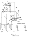
- the power braking system 10 has a pilot valve 11 operated by an adjacent brake pedal 12. Pilot valve 11 is supplied with pressurised fluid from an accumulator 13 which is charged by a pump 14.
- Pilot valve 11 supplies the fluid to a first pilot drilling 15a at one end of a relay valve 15 via line 16.
- Relay valve 15 also receives pressurised fluid from accumulator 13 via line 17 and, when valve 15 is an open condition supplies this pressurised fluid to brakes 18 via line 19.
- the pressure in line 19 is fed back to a second pilot drilling 15b at the other end of relay valve 15 by a feed back drilling 20.
- both the pilot valve 11 and the relay valve 15 are provided with return lines 21 and 22 which return unwanted fluid to a reservoir 23 from which pump 14 itself draws fluid.
- the drain line 22 is provided with a U-shaped bend 24 which tends to trap fluid in the drain line 22 no matter what the inclination of the reservoir 23. This is particularly important in an agricultural tractor which may be required to operate in various inclined positions.
- This U-bend 24 stops air being drawn in to the system via drain line 22 as well as restricting the drainage from the system referred to above.
- drain line 21 from the pilot valve 11 is also provided with a U-bend section 25 which again prevents the entry of air into the system and the drainage of fluid from the system.
- the above arrangement enables the reservoir 23 to be positioned below both the pilot valve I and the relay valve 15 which is a preferred arrangement in most agricultural tractor.
Landscapes
- Engineering & Computer Science (AREA)
- Transportation (AREA)
- Mechanical Engineering (AREA)
- Braking Systems And Boosters (AREA)
- Valves And Accessory Devices For Braking Systems (AREA)
Abstract
Description
- This invention relates to hydraulic power braking systems and in particular to such systems for use in agricultural tractors.
- Power braking systems are known in which a pilot valve or valves operated by an adjacent brake pedal or pedals control the movement of a relay valve or valves which in turn control the application of stored pressurised fluid to associated brakes.
- Problems can arise with such hydraulic power braking systems due to fluid draining from the system between the pilot and relay valves and this can cause delay in braking and make the braking power applied hard to control.
- Thus according to the present invention there is provided a hydraulic power braking circuit for a vehicle having, a reservoir fur hydraulic fluid, a pump which draws hydraulic fluid from the reservoir for charging a hydraulic pressure vessel with pressurised fluid, a driver operated pilot valve for directing pressurised fluid from the pressure vessel to open a relay valve which connects the pressurised fluid to brake actuators to apply associated brakes, the pilot valve and relay valve both having return lines to dump fluid to the reservoir when not operating the relay valve or brake actuators respectively, both return lines having end configurations within the reservoir which ensure that the ends of these return lines retain fluid therein no matter what inclination of the reservoir occurs during use of the vehicle to avoid the entry of air into the circuit.
- The ends of the return lines are arranged to remain at all times below the level of fluid in the reservoir to prevent the entry of air into the circuit.
- The ends of the return lines preferably include U-bend portions to trap fluid therein and thus avoid the entry of air into the circuit even at high inclinations of the reservoir.
- Such an arrangement allows the reservoir to be located below at least one of the pilot valve and relay valve.
- One embodiment of the present invention will now be described, by way of example only, with reference to the accompanying
Figure 1 which diagrammatically shows a power braking system in accordance with the present invention. - Referring to
Figure 1 , thepower braking system 10 has a pilot valve 11 operated by anadjacent brake pedal 12. Pilot valve 11 is supplied with pressurised fluid from anaccumulator 13 which is charged by apump 14. - Pilot valve 11 supplies the fluid to a first pilot drilling 15a at one end of a
relay valve 15 via line 16.Relay valve 15 also receives pressurised fluid fromaccumulator 13 vialine 17 and, whenvalve 15 is an open condition supplies this pressurised fluid to brakes 18 vialine 19. The pressure inline 19 is fed back to a second pilot drilling 15b at the other end ofrelay valve 15 by afeed back drilling 20. - Thus in order to operate the
brakes 18 thepedal 12 is depressed which opens pilot valve 11 which in turn pressurises the first pilot drilling 15a ofrelay valve 15 with a pressure proportional to the movement ofpedal 13. This in turn displaces the spool of valve to open the valve and thus supply a pressure toline 19 fromaccumulator 13 which is again proportional to the movement ofpedal 12. - In accordance with the present invention both the pilot valve 11 and the
relay valve 15 are provided withreturn lines reservoir 23 from whichpump 14 itself draws fluid. - To avoid the risk of fluid draining from line 16 when
relay valve 15 is in the closed position by leaking between the valve slide 15c and its associatedbore 15d into thedrain line 22, thedrain line 22 is provided with aU-shaped bend 24 which tends to trap fluid in thedrain line 22 no matter what the inclination of thereservoir 23. This is particularly important in an agricultural tractor which may be required to operate in various inclined positions. This U-bend 24 stops air being drawn in to the system viadrain line 22 as well as restricting the drainage from the system referred to above. - Similarly the
drain line 21 from the pilot valve 11 is also provided with aU-bend section 25 which again prevents the entry of air into the system and the drainage of fluid from the system. - By using the provision of U-bend 24 the drainage of the line 16 between the pilot valve I I and
relay valve 15 can be controlled and thus the quick brake response retained no matter what the inclination of the tractor. This greatly assists in controlling the brake power which is applied whenpedal 12 is depressed. - The above arrangement enables the
reservoir 23 to be positioned below both the pilot valve I and therelay valve 15 which is a preferred arrangement in most agricultural tractor.
Claims (4)
- A hydraulic power braking circuit (10) for a vehicle having a reservoir (23) for hydraulic fluid, a pump (14) which draws hydraulic fluid from the reservoir for charging a hydraulic pressure vessel (13) with pressurised fluid, a driver operated pilot valve (11) for directing pressurised fluid from the pressure vessel to open a relay valve (15) which connects the pressurised fluid to brake actuators to apply associated brakes (18), circuit being characterised in that the pilot valve (11) and relay valve (15) both having return lines (21,22) to dump fluid to the reservoir (23) when not operating the relay valve or brake actuators respectively, both return lines having end configurations (24,25) within the reservoir (23) which ensure that the ends of these return lines retain fluid therein no matter what inclination of the reservoir occurs during use of the vehicle to avoid the entry of air into the circuit.
- A circuit according to claim 1 characterised in that the ends (24,25) of the return lines (21,22) are arranged at all times to remain below the level of fluid in the reservoir to avoid the entry of air into the circuit.
- A circuit according to claim 1 or 2 characterised in that the ends of the return lines (21,22) both include U-bend portions (24,25) to trap fluid therein and thus avoid the entry of air into the circuit.
- A circuit according to any one of claims I to 3 in which the reservoir (23) is located below at least one of the pilot valve (11) and relay valve (15).
Applications Claiming Priority (1)
| Application Number | Priority Date | Filing Date | Title |
|---|---|---|---|
| GB0915310A GB0915310D0 (en) | 2009-09-03 | 2009-09-03 | Power braking system |
Publications (2)
| Publication Number | Publication Date |
|---|---|
| EP2292485A2 true EP2292485A2 (en) | 2011-03-09 |
| EP2292485A3 EP2292485A3 (en) | 2013-10-09 |
Family
ID=41203068
Family Applications (1)
| Application Number | Title | Priority Date | Filing Date |
|---|---|---|---|
| EP10009029.9A Withdrawn EP2292485A3 (en) | 2009-09-03 | 2010-08-31 | Power braking system |
Country Status (2)
| Country | Link |
|---|---|
| EP (1) | EP2292485A3 (en) |
| GB (1) | GB0915310D0 (en) |
Cited By (1)
| Publication number | Priority date | Publication date | Assignee | Title |
|---|---|---|---|---|
| GB2588187A (en) * | 2019-10-11 | 2021-04-21 | Caterpillar Inc | Braking system |
Family Cites Families (4)
| Publication number | Priority date | Publication date | Assignee | Title |
|---|---|---|---|---|
| DE4212031C1 (en) * | 1992-04-09 | 1993-05-19 | Mannesmann Rexroth Gmbh, 8770 Lohr, De | Hydraulic switching for vehicle multicircuit brakes - has central reservoir incorporated in main supply line in front of branches to individual brake circuits |
| DE19546682A1 (en) * | 1995-12-14 | 1997-06-19 | Bosch Gmbh Robert | Hydraulic brake system for motor vehicles |
| FR2831504B1 (en) * | 2001-10-25 | 2004-01-23 | Bosch Gmbh Robert | HYDRAULIC TANK FOR HYDRAULIC CIRCUIT WITH INCREASED SUPPLY SECURITY AND BRAKING SYSTEM COMPRISING SUCH A TANK |
| US20100187900A1 (en) * | 2007-10-05 | 2010-07-29 | Robert Bosch Ghbh | Hydraulic power brake system |
-
2009
- 2009-09-03 GB GB0915310A patent/GB0915310D0/en not_active Ceased
-
2010
- 2010-08-31 EP EP10009029.9A patent/EP2292485A3/en not_active Withdrawn
Non-Patent Citations (1)
| Title |
|---|
| None |
Cited By (1)
| Publication number | Priority date | Publication date | Assignee | Title |
|---|---|---|---|---|
| GB2588187A (en) * | 2019-10-11 | 2021-04-21 | Caterpillar Inc | Braking system |
Also Published As
| Publication number | Publication date |
|---|---|
| GB0915310D0 (en) | 2009-10-07 |
| EP2292485A3 (en) | 2013-10-09 |
Similar Documents
| Publication | Publication Date | Title |
|---|---|---|
| CN112622853B (en) | Electro-hydraulic braking device | |
| EP2509834B1 (en) | Power braking system with steering assist | |
| DE102014220440A1 (en) | Brake control device and brake system for vehicles | |
| DE102012205859A1 (en) | Brake system for motor vehicles and method for operating a brake system | |
| DE102009005937A1 (en) | Electrohydraulic braking system and method of operation | |
| DE102012023341A1 (en) | Vehicle control device | |
| US20110252778A1 (en) | Hydraulic system | |
| DE102009054985A1 (en) | Braking system for motor vehicle, has piston led into housing and limiting hydraulic area, where pressure application of piston effects movement of another piston in operating direction | |
| DE102010003082A1 (en) | Brake assembly for motor vehicle, has high pressure storage and pressure regulating valve arrangement, power port, pressure supply terminal and return port | |
| EP3265349B1 (en) | A braking system | |
| DE102007038961A1 (en) | Brake control device and brake control method | |
| DE102011083237B4 (en) | Brake system and procedure for its operation | |
| DE102010038327A1 (en) | Brake system for motor vehicles | |
| DE112008003265B4 (en) | Brake control device and brake control method | |
| WO2008074448A1 (en) | Electrohydraulic control module | |
| DE102022201758A1 (en) | SIMULATOR VALVE | |
| EP1799522B1 (en) | Method for prefilling a low-pressure reservoir on a motor vehicle braking system | |
| DE102012223497A1 (en) | Brake system for motor vehicle, has inlet valves opened during normal braking, and system pressure conducting sections formed between inlet connections and pressure side of pump for assigning pressure medium volume flow to brakes | |
| ATE423710T1 (en) | HYDRAULIC BRAKE SYSTEM FOR A LAND VEHICLE WITH PRESSURE CONTROL | |
| WO1999005012A1 (en) | Fully hydraulic servobrake / master cylinder unit | |
| DE102014116732B4 (en) | Braking device of a vehicle with electric and by a pneumatic Notzuspanneinrichtung zuspannbarer parking brake and vehicle with such a braking device | |
| KR101532785B1 (en) | Parking brake and pilot emergency release system for construction machinery | |
| DE102014215379B4 (en) | Braking system for a vehicle | |
| WO2016155721A1 (en) | Clutch actuation system | |
| CN113165624B (en) | Hydraulic braking devices for off-road vehicles |
Legal Events
| Date | Code | Title | Description |
|---|---|---|---|
| PUAI | Public reference made under article 153(3) epc to a published international application that has entered the european phase |
Free format text: ORIGINAL CODE: 0009012 |
|
| AK | Designated contracting states |
Kind code of ref document: A2 Designated state(s): AL AT BE BG CH CY CZ DE DK EE ES FI FR GB GR HR HU IE IS IT LI LT LU LV MC MK MT NL NO PL PT RO SE SI SK SM TR |
|
| AX | Request for extension of the european patent |
Extension state: BA ME RS |
|
| PUAL | Search report despatched |
Free format text: ORIGINAL CODE: 0009013 |
|
| AK | Designated contracting states |
Kind code of ref document: A3 Designated state(s): AL AT BE BG CH CY CZ DE DK EE ES FI FR GB GR HR HU IE IS IT LI LT LU LV MC MK MT NL NO PL PT RO SE SI SK SM TR |
|
| AX | Request for extension of the european patent |
Extension state: BA ME RS |
|
| RIC1 | Information provided on ipc code assigned before grant |
Ipc: B60T 13/14 20060101ALN20130903BHEP Ipc: B60T 17/06 20060101AFI20130903BHEP |
|
| 17P | Request for examination filed |
Effective date: 20140409 |
|
| RBV | Designated contracting states (corrected) |
Designated state(s): AL AT BE BG CH CY CZ DE DK EE ES FI FR GB GR HR HU IE IS IT LI LT LU LV MC MK MT NL NO PL PT RO SE SI SK SM TR |
|
| STAA | Information on the status of an ep patent application or granted ep patent |
Free format text: STATUS: THE APPLICATION IS DEEMED TO BE WITHDRAWN |
|
| 18D | Application deemed to be withdrawn |
Effective date: 20140410 |