EP2292454B1 - Method for operating a heating system of an electric vehicle - Google Patents
Method for operating a heating system of an electric vehicle Download PDFInfo
- Publication number
- EP2292454B1 EP2292454B1 EP10174871A EP10174871A EP2292454B1 EP 2292454 B1 EP2292454 B1 EP 2292454B1 EP 10174871 A EP10174871 A EP 10174871A EP 10174871 A EP10174871 A EP 10174871A EP 2292454 B1 EP2292454 B1 EP 2292454B1
- Authority
- EP
- European Patent Office
- Prior art keywords
- cooling circuit
- temperature
- heating
- heat pump
- heat
- Prior art date
- Legal status (The legal status is an assumption and is not a legal conclusion. Google has not performed a legal analysis and makes no representation as to the accuracy of the status listed.)
- Active
Links
Images


Classifications
-
- B—PERFORMING OPERATIONS; TRANSPORTING
- B60—VEHICLES IN GENERAL
- B60H—ARRANGEMENTS OF HEATING, COOLING, VENTILATING OR OTHER AIR-TREATING DEVICES SPECIALLY ADAPTED FOR PASSENGER OR GOODS SPACES OF VEHICLES
- B60H1/00—Heating, cooling or ventilating [HVAC] devices
- B60H1/00357—Air-conditioning arrangements specially adapted for particular vehicles
- B60H1/00385—Air-conditioning arrangements specially adapted for particular vehicles for vehicles having an electrical drive, e.g. hybrid or fuel cell
- B60H1/00392—Air-conditioning arrangements specially adapted for particular vehicles for vehicles having an electrical drive, e.g. hybrid or fuel cell for electric vehicles having only electric drive means
-
- B—PERFORMING OPERATIONS; TRANSPORTING
- B60—VEHICLES IN GENERAL
- B60H—ARRANGEMENTS OF HEATING, COOLING, VENTILATING OR OTHER AIR-TREATING DEVICES SPECIALLY ADAPTED FOR PASSENGER OR GOODS SPACES OF VEHICLES
- B60H1/00—Heating, cooling or ventilating [HVAC] devices
- B60H1/00478—Air-conditioning devices using the Peltier effect
-
- B—PERFORMING OPERATIONS; TRANSPORTING
- B60—VEHICLES IN GENERAL
- B60H—ARRANGEMENTS OF HEATING, COOLING, VENTILATING OR OTHER AIR-TREATING DEVICES SPECIALLY ADAPTED FOR PASSENGER OR GOODS SPACES OF VEHICLES
- B60H1/00—Heating, cooling or ventilating [HVAC] devices
- B60H1/00642—Control systems or circuits; Control members or indication devices for heating, cooling or ventilating devices
- B60H1/00814—Control systems or circuits characterised by their output, for controlling particular components of the heating, cooling or ventilating installation
- B60H1/00878—Control systems or circuits characterised by their output, for controlling particular components of the heating, cooling or ventilating installation the components being temperature regulating devices
- B60H1/00899—Controlling the flow of liquid in a heat pump system
-
- B—PERFORMING OPERATIONS; TRANSPORTING
- B60—VEHICLES IN GENERAL
- B60H—ARRANGEMENTS OF HEATING, COOLING, VENTILATING OR OTHER AIR-TREATING DEVICES SPECIALLY ADAPTED FOR PASSENGER OR GOODS SPACES OF VEHICLES
- B60H1/00—Heating, cooling or ventilating [HVAC] devices
- B60H1/00642—Control systems or circuits; Control members or indication devices for heating, cooling or ventilating devices
- B60H1/00814—Control systems or circuits characterised by their output, for controlling particular components of the heating, cooling or ventilating installation
- B60H1/00878—Control systems or circuits characterised by their output, for controlling particular components of the heating, cooling or ventilating installation the components being temperature regulating devices
- B60H2001/00949—Control systems or circuits characterised by their output, for controlling particular components of the heating, cooling or ventilating installation the components being temperature regulating devices comprising additional heating/cooling sources, e.g. second evaporator
Definitions
- the invention relates to operating methods for a heating system for an electrically driven vehicle according to the preamble of claim 1 as shown in the DE 19850829 C1 is revealed ..
- Under an electrically driven vehicle according to the invention is basically any vehicle to understand that at least temporarily only electrically, so without a complementary running internal combustion engine, is driven.
- the pure electric vehicles and full hybrid vehicles are driven.
- a drive component within the meaning of the invention may be any component of the vehicle drive generating waste heat, such as an electric motor or power electronics.
- a brake connected to the cooling circuit is to be understood here as well.
- a heat pump member according to the invention is designed as a Peltier element.
- a Peltier element is to be understood as meaning any heat pump element that uses the thermoelectric effect for pumping heat.
- the electrical heating element is designed as a PTC heating element, whereby a reliable, cost-effective and powerful heating is available.
- the heating member may be arranged in a possible detail design depending on the requirements directly in an air flow for the passenger area or in the cooling circuit for heating the coolant. In principle, both a heating element in the air flow and in the cooling circuit may be provided, but this is avoided for reasons of cost preferred embodiments. It is understood that the heating element may comprise a plurality of PTC elements and / or a plurality of heating elements may be present.
- another cooling circuit in particular for cooling the energy storage device, is thermally connected to the cooling circuit via a further heat pump element.
- a further heat pump element is thermally connected to the cooling circuit via a further heat pump element.
- the object of the invention is achieved by an operating method having the features of claim 1.
- the amount of energy required to heat the passenger area from the energy store can be minimized.
- An optimization of ⁇ T is particularly important when designing the heat pump member as a Peltier element, since the operating parameters of Peltier elements to optimize their efficiency are particularly critical.
- the determination of the temperatures in the sense of the invention not only means a direct measurement of the temperatures, but also a determination by measuring one or more other parameters with which the temperature to be determined is uniquely correlated.
- an adaptation thereby takes place by the step: increasing or maintaining a pumping capacity of the heat pump member, if a temporal change of the temperature TK of the cooling circuit is greater than zero. This avoids that the temperature of the cooling circuit is lowered by pumping heat.
- the limit power or maximum pump power is given when the temperature difference can not be increased by increasing the electric current through the Peltier element. Depending on the operating mode, this state can serve as a suitable limiting condition for an increase in the electrical current through the Peltier element. This can be useful at least when the temperature level of the cooling circuit is sufficiently high and / or an expected travel time allows a maximum heat output from the cooling circuit.
- an additional heating of the cooling circuit by the formed as a Peltier element heat pump member corresponds to an operation of the Peltier element with a sufficiently large current in an area with COP ⁇ 1, so that as a result, a heat input into the cooling circuit takes place.
- the second possibility can be present in addition to the first, so that in an individual case a reconciliation of an otherwise independent, especially learning system can take place.
- an operating method comprises the step of maximizing heat transfer from the refrigeration cycle to the air flow by means of the heat pump member, in a preferred embodiment by maximizing the temperature difference TK-TWC.
- the amount of energy used for heating is generally taken from the heat loss and possibly other, the cooling circuit heating heat sources and minimally from the necessary for the vehicle drive energy of the electrical energy storage.
- maximizing the temperature difference TK-TWC can at least temporarily a largest possible heating power can be removed from the heat of the cooling circuit, so that the taken from the energy storage for heating electrical power is minimal relative to the total heating power.
- FIG. 1 shown heating system for an electric vehicle comprises a cooling circuit 1, in which a coolant, for example a water-glycol mixture, is circulated. It transports waste heat from drive components, in the present case an electric motor 2 of a vehicle drive and from a power electronics 3 provided for its regulation, to a heat pump element 4, which is designed as a Peltier element.
- a coolant for example a water-glycol mixture
- the Peltier element 4 is thermally connected with its one side to the coolant and with its other side to a heating air flow 5, which is supplied to a passenger area of the vehicle.
- a heating element in the form of a PTC heating element 6 is provided for heating the air flow 5.
- the PTC heating element 6 and the Peltier element 4 are formed as an integrated unit.
- a controllable valve assembly 7 is provided, by means of which the coolant flow can be passed either through a bypass 8 or wholly or partially by a coolant cooler 9 can be flowed around with outside air.
- a fan 10 is also provided on the radiator 9, a fan 10 is also provided.
- Another radiator 11 of a further cooling circuit 12 is arranged in front of the radiator 9.
- the further cooling circuit 12 is used exclusively for cooling an electrical energy store in the form of a lithium-ion battery 13, the temperature level in the battery cooling circuit 12 during normal operation being lower than in the cooling circuit 1 of the drive components 2, 3.
- an optional heat pump element 14 which is also designed as a Peltier element, heat from the usually colder cooling circuit 12 in the usually warmer cooling circuit 1 can be pumped.
- valve arrangement unless expressly stated otherwise, conducts the coolant bypassing the outer cooler 9 through the bypass 8.
- cooling circuit 1 is adequately insulated by appropriate measures, so that as far as possible no loss of heat is released to the outside.
- the PTC heating element or heating element 6 is not disposed directly in the air stream 5, but in the cooling circuit 1. It is therefore thermally with the Coolant in connection and heating of the air flow 5 through the heating element 6 takes place in contrast to the first example only indirectly via a heater of the coolant.
- the temperature of the refrigeration cycle TK, the temperature of the cold, associated with the cooling circuit side of the Peltier element TWC and the temperature of the warm, 5 associated with the air flow side of the Peltier element TL are measured and monitored.
- the heat transfer from the cooling circuit 1 to the air 5 by the Peltier element 4 is optimized, so that at least over the entire duration of an operating cycle of the vehicle as minimal as possible use of electrical energy of the energy storage 13 for the heating of the passenger compartment.
- condition (1) will usually occur first and represent the preferred solution.
- Condition (2) could lead to an undesirably strong cooling of the cooling circuit. It is conceivable to use condition (2) under the additional condition that the temperature of the cooling circuit TK does not fall below the outside temperature or a defined distance to the outside temperature.
- the air outlet temperature is set as low as reasonably ergonomic.
- the temperatures and flow velocities in the cooling circuit 1 may change due to external influences or desired interventions during operation, it must be checked at certain time intervals whether the optimum according to the aforementioned criteria is still present and if necessary counteracted accordingly.
- the cooling circuit 1 and its heat sources 2, 3 and the energy storage 13 before moving the vehicle.
- this is done while the vehicle is connected to the power grid, so that the Ladezu-stand of the energy storage 13 can be maintained at a high level.
- the cooling circuit 1 and the thermally connected heat capacities 2, 3 need not be heated by loss heat flows, but due to their high temperature levels can immediately cause a high COP of the Schusys- tems. It can be set directly a balance between heat sources and heat sinks, so that the cycle temperature TK remains largely constant.
- the optimal heating strategy depends essentially on the expected service life of the vehicle.
- An expected value tBE for the operating time at the beginning of a journey can be obtained by a manual input by the operator or also by a prognosis based on a statistically determined, typical user behavior.
- the control of the heating system can be configured as an adaptive system, which carries out a continuous optimization of the provision of expected values tBE of an operating time or driving time duration.
- such an operation may be present as a standard setting, with an additional "override" being provided by manual input of an expected value tBE in individual cases.
- the operating time is much greater than a typical heating time of the cooling circuit. Then it is effective to heat the cooling circuit 1 before a heat extraction initially up to an upper limit temperature or maximum stationary temperature of the cooling circuit. This can be achieved by an active auxiliary heating, for example by means of water-side heating elements 6 according to the heating system Fig. 2 ., be accelerated. Depending on the requirements, a wait can be sufficient until the waste heat sources 2, 3 have heated the circuit 1.
- an optimal steady-state cycle temperature TKE is now to be determined, depending on the conditions, in particular the expected, not substantially interrupted travel time.
- heating of the coolant circuit takes place preferably without heat removal up to the optimum stationary temperature TKE (transient phase), after which the temperature TKE is kept substantially constant while pumping through the heat pump member or Peltier element 4 (stationary phase).
- Fig. 3 shows by way of example a diagram of the cooling circuit temperature over time, starting from the start of the vehicle at a temperature Too. Entered are three pairs of operating times tB1, tB2, tB3 and respectively associated optimal stationary temperatures TKE.
- the temperature profile is idealized, namely first a linear increase from Too to TKE, B3 (transient phase) and subsequently a constant curve at TKE, 83 (stationary phase).
- the same rules apply as under a) "simple system without preconditioning").
- the target temperature of the circuit can be determined.
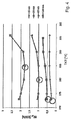
- Fig. 4 Simulation results for a heating system based on four different expected travel times tBE between 15 minutes and 120 minutes. It was a heating of the circuit 1 of Too on the respective stationary temperature without active auxiliary heating, so only by waste heat performance of the drive components 2, 3 is based.
- the other basic data of the modeled heating system are:
- Fig. 4 in each case the total energy consumed is shown above the (varied) stationary temperature TKE. It shows in each case a marked by a circle minimum energy consumption at different stationary temperatures as a function of the vehicle tBE.
- a preconditioning can be made via power from the network and, in addition, e.g. due to low waste heat power in rush hour, be actively heated by means of water-side PTC heaters 6 to prevent a drop in the temperature of the cooling circuit below the optimum level.
- the circuit and its connected thermal masses can be heated by means of the Peltier elements 4 in addition to or instead of waste heat or water-side PTC heaters 6. This is achieved by the power supply after the presence of the condition (2) of a) is further increased and operated in accordance with the Peltier elements with a COP ⁇ 1.
Description
Die Erfindung betrifft Betriebsverfahren für ein Heizsystem für ein elektrisch antreibbares Fahrzeug nach dem Oberbegriff des Anspruchs 1 wie es in der
Aus der Entwicklung von elektrisch antreibbaren Fahrzeugen ist die Problematik bekannt, dass aufgrund der im Vergleich zum Antrieb mit Verbrennungsmotoren geringen Abwärmeleistungen eine Heizung eines Passagierbereichs problematisch ist. Ein bekannter Ansatz besteht darin, die zur Verfügung stehende Energie aus einem elektrischen Energiespeicher zum Betrieb einer Widerstandsheizung wie etwa einem PTC-Heizglied (PTC = Positive Temperature Coefficient) zu verwenden.From the development of electrically driven vehicles, the problem is known that heating of a passenger area is problematic due to the low compared to the drive with internal combustion engines waste heat. One known approach is to use the available energy from an electrical energy store to operate a resistance heater such as a PTC (Positive Temperature Coefficient) heating element.
Es ist die Aufgabe der Erfindung, ein Betriebsverfahren für ein Heizsystem für ein elektrisch antreibbares Fahrzeug anzugeben, durch das eine gespeicherte elektrische Energie möglichst sparsam verwendet wird.It is the object of the invention to specify an operating method for a heating system for an electrically drivable vehicle, by which a stored electrical energy is used as sparingly as possible.
Diese Aufgabe wird für ein eingangs genanntes Heizsystem erfindungsgemäß mit den kennzeichnenden Merkmalen des Anspruchs 1 gelöst. Durch die Koppelung des Kühlkreises mit einer Wärmepumpe kann die elektrische Energie zur Heizung mit einem Wirkungsgrad (COP, Coefficient Of Performance) von >1 betrieben werden, wobei auch bei niedrigen Kühlkreislauftemperaturen eine ausreichende Beheizung des Passagierbereichs möglich ist.This object is achieved for an aforementioned heating system according to the invention with the characterizing features of
Unter einem elektrisch antreibbaren Fahrzeug im Sinne der Erfindung ist grundsätzlich jedes Fahrzeug zu verstehen, dass zumindest zeitweise nur elektrisch, also ohne einen ergänzend laufenden Verbrennungsmotor, angetrieben wird. Insbesondere sind die reine Elektrofahrzeuge und Vollhybridfahrzeuge. Besonders für reine Elektrofahrzeuge ist der Einfluss einer Heizung auf die Reichweite des Fahrzeugs bedeutsam. Eine Antriebskomponente im Sinne der Erfindung kann jede Abwärme erzeugende Komponente des Fahrzeugantriebs sein, wie etwa ein Elektromotor oder eine Leistungselektronik. Auch eine an den Kühlkreislauf angebundene Bremse ist hierunter zu verstehen.Under an electrically driven vehicle according to the invention is basically any vehicle to understand that at least temporarily only electrically, so without a complementary running internal combustion engine, is driven. In particular, the pure electric vehicles and full hybrid vehicles. Especially for pure electric vehicles, the influence of a heater on the range of the vehicle is significant. A drive component within the meaning of the invention may be any component of the vehicle drive generating waste heat, such as an electric motor or power electronics. A brake connected to the cooling circuit is to be understood here as well.
Ein Wärmepumpenglied im Sinne der Erfindung ist als Peltier-Element ausgebildet. Unter einem Peltier-Element im Sinne der Erfindung ist jedes Wärmepumpenglied zu verstehen, das den thermoelektrischen Effekt zum Pumpen von Wärme nutzt.A heat pump member according to the invention is designed as a Peltier element. For the purposes of the invention, a Peltier element is to be understood as meaning any heat pump element that uses the thermoelectric effect for pumping heat.
In bevorzugter Ausführungsform ist das elektrische Heizglied als PTC-Heizelement ausgebildet, wodurch eine betriebssichere, kostengünstige und leistungsstarke Zuheizung zur Verfügung steht.In a preferred embodiment, the electrical heating element is designed as a PTC heating element, whereby a reliable, cost-effective and powerful heating is available.
Das Heizglied kann in möglicher Detailgestaltung je nach Anforderungen unmittelbar in einem Luftstrom für den Passagierbereich angeordnet sein oder in dem Kühlkreislauf zur Erwärmung des Kühlmittels. Grundsätzlich kann sowohl ein Heizglied in dem Luftstrom als auch in dem Kühlkreislauf vorgesehen sein, was aber bei aus Kostengründen bevorzugten Ausführungsformen vermieden wird. Es versteht sich, dass das Heizglied mehrere PTC-Elemente umfassen kann und/oder mehrere Heizglieder vorliegen können.The heating member may be arranged in a possible detail design depending on the requirements directly in an air flow for the passenger area or in the cooling circuit for heating the coolant. In principle, both a heating element in the air flow and in the cooling circuit may be provided, but this is avoided for reasons of cost preferred embodiments. It is understood that the heating element may comprise a plurality of PTC elements and / or a plurality of heating elements may be present.
Alternativ ist ein weiterer Kühlkreislauf, insbesondere zur Kühlung des Energiespeichers, über ein weiteres Wärmepumpenglied thermisch an den Kühlkreislauf angebunden. Dies ist zumindest dann vorteilhaft, wenn die am Energiespeicher, etwa einer Lithium-lonen-Batterie zu etablierende Temperatur unterhalb der Kühlkreislaultemperatur liegt. Eine typische Betriebstemperatur des Kühlkreislaufs liegt bei etwa 60 °C, wogegen die Temperatur eines Kühlkreises für eine Lithium-lonen-Batterie im Bereich 10 °C bis 30 °C liegen sollte, um eine optimale Lebenserwartung der Batterie sicherzustellen.Alternatively, another cooling circuit, in particular for cooling the energy storage device, is thermally connected to the cooling circuit via a further heat pump element. This is advantageous at least when the temperature to be established at the energy store, for example a lithium-ion battery, is below the refrigerating circuit temperature. A typical operating temperature of the refrigeration cycle is about 60 ° C, whereas the temperature of a refrigeration cycle for a lithium ion battery should be in the range of 10 ° C to 30 ° C to ensure optimum life expectancy of the battery.
Die Aufgabe der Erfindung wird durch ein Betriebsverfahren mit den Merkmalen des Anspruchs 1 gelöst. Durch die Bestimmung und Überwachung der Temperaturen TL, TK und TWC kann die zum Heizen des Fahrgastbereichs aus dem Energiespeicherbenötigte Energiemenge minimiert werden. Insbesondere erfolgt diese Optimierung unter Berücksichtigung der Temperaturdifferenz ΔT = TWC - TK zwischen der kalten Seite des Wärmepumpenglieds TWC und der des Kühlkreislaufs TK. Eine Optimierung von ΔT ist besonders bei Ausbildung des Wärmepumpenglieds als Peltier-Element wichtig, da die Betriebsparameter von Peltier-Elementen zur Optimierung ihres Wirkungsgrads besonders kritisch sind. Unter der Bestimmung der Temperaturen im Sinne der Erfindung ist nicht nur eine direkte Messung der Temperaturen zu verstehen, sondern auch eine Ermittlung durch Messung einer oder mehrerer anderer Parameter, mit denen die zu bestimmende Temperatur eindeutig korreliert ist.The object of the invention is achieved by an operating method having the features of
Erfindungsgemäß umfasst das Verfahren folgende Schritte:
- Bestimmen eines Erwartungswertes für eine Nutzungsdauer des Fahrzeugs zu Beginn einer Nutzung, und
- Betrieb des als Peltier-Element ausgebildeten Wärmepumpenglieds in Abhängigkeit vom Erreichen einer vorbestimmten Kühlkreistemperatur TKE, wobei TKE in Abhängigkeit von dem Erwartungswert der Nutzungsdauer gewählt wird, und insbesondere monoton mit dem Erwartungswert ansteigt. Hierdurch wird der Energieverbrauch besonders effektiv optimiert, da das Betriebsverfahren je nach anstehenden Aufgaben des Fahrzeugs angepasst wird.
- Determining an expected value for a useful life of the vehicle at the beginning of use, and
- Operation of the Peltier element formed as a heat pump member in response to reaching a predetermined cooling circuit temperature TKE, wherein TKE is selected in dependence on the expected value of the useful life, and in particular increases monotonically with the expected value. As a result, the energy consumption is optimized particularly effective, since the operating method is adapted depending on the upcoming tasks of the vehicle.
In bevorzugter Detailgestaltung erfolgt eine Anpassung dabei durch den Schritt: Erhöhen oder Beibehalten einer Pumpleistung des Wärmepumpenglieds, falls eine zeitliche Änderung der Temperatur TK des Kühlkreislaufs größer Null ist. Hierdurch wird vermieden, dass die Temperatur des Kühlkreislaufs durch ein Pumpen von Wärme abgesenkt wird.In a preferred detailed design, an adaptation thereby takes place by the step: increasing or maintaining a pumping capacity of the heat pump member, if a temporal change of the temperature TK of the cooling circuit is greater than zero. This avoids that the temperature of the cooling circuit is lowered by pumping heat.
Weiterhin bevorzugt umfasst das Verfahren den Schritt: Ermitteln einer Grenzleistung des Peltier-Elements aus dem zeitlichen Verhalten der Temperaturdifferenz ΔT = TWC - TK. Die Grenzleistung bzw. maximale Pumpleistung ist dann gegeben, wenn die Temperaturdifferenz durch eine Erhöhung des elektrischen Stroms durch das Peltier-Element nicht mehr erhöht werden kann. Dieser Zustand kann je nach Betriebsmodus als geeignete Grenzbedingung für eine Erhöhung des elektrischen Stroms durch das Peltier-Element dienen. Dies kann zumindest dann sinnvoll sein, wenn das Temperaturniveau des Kühlkreislaufs ausreichend hoch ist und/oder eine erwartete Fahrzeit eine maximale Wärmeleistung aus dem Kühlkreislauf erlaubt.Furthermore, the method preferably comprises the step of determining a limiting power of the Peltier element from the time behavior of the temperature difference ΔT = TWC-TK. The limit power or maximum pump power is given when the temperature difference can not be increased by increasing the electric current through the Peltier element. Depending on the operating mode, this state can serve as a suitable limiting condition for an increase in the electrical current through the Peltier element. This can be useful at least when the temperature level of the cooling circuit is sufficiently high and / or an expected travel time allows a maximum heat output from the cooling circuit.
Allgemein bevorzugt ist es vorgesehen, dass der Schritt eines zusätzlichen Heizens durch das Heizglied erfolgt, falls die Temperatur TL einen vorgegebenen Wert durch Schritt d, nicht erreicht. Dies bedeutet, dass im Interesse einer ausreichenden Beheizung des Fahrgastraums eine Zusatzheizung mit COP = 1 (reine Widerstandsheizung) erfolgen muss, da eine reine Wärmepumpenheizung mit COP > 1 nicht ausreichend ist.Generally, it is provided that the step of additional heating by the heating element takes place if the temperature TL does not reach a predetermined value by step d. This means that, in the interests of adequate heating of the passenger compartment, additional heating with COP = 1 (pure resistance heating) must take place, since pure heat pump heating with COP> 1 is not sufficient.
Bei einem besonders bevorzugten Betriebsverfahren ist der Schritt vorgesehen: Aufheizen eines Wärmespeichers, insbesondere eines Fahrzeuginnenraums, des Kühlkreises, des Energiespeichers und/oder der Antriebskomponente, während eines stationären Ladevorgangs des Energiespeichers. Hierdurch kann während der Fahrt eine teilweise Heizung des Fahrgastraums durch gespeicherte Wärme erfolgen bzw. die Wärmekapazitäten von Kühlkreislauf, Fahrzeuginnenraum, Energiespeicher und/oder Antriebskomponente müssen nicht durch wertvolle elektrische Energie aus dem Energiespeicher gefüllt werden. Unter dem Aufheizen des Energiespeichers ist auch die Heizung eines gegebenenfalls mit dem Energiespeichers verbundenen, eigenen Kühlkreislaufs zu verstehen. Die Aufheizung des Energiespeichers im Zuge eines stationären Ladevorgangs ist besonders günstig, da der Energiespeicher aufgrund seiner hohen Masse von bis zu mehreren hundert Kilogramm eine große Wärmekapazität darstellt Auch bei relativ niedrigen Betriebstemperaturen, wie sie zum Beispiel Lithium-Ionen-Batterien erfordern, enthält der Energiespeicher daher eine große, durch ein erfindungsgemäßes Heizsystem nutzbare Wärmemenge. Der Transport dieser Wärme von dem Energiespeicher in den Passagierbereich kann zum Beispiel durch eine thermische Anbindung eines Kühlkreislaufs des Energiespeichers an den Kühlkreislauf erfolgen, zum Beispiel mittels eines Wärmepumpenglieds, oder auch auf andere Weise. Allgemein bevorzugt erfolgt der Transport aber mittels eines Wärmepumpenglieds, da das Temperaturniveau zumindest im Fall von aktuellen Lithium-Ionen-Batterien nur wenig oberhalb oder sogar unterhalb einer Temperatur des Passagierbereichs liegen sollte.
- Allgemein lässt sich das Auffinden der vorbestimmten Kühlkreistemperatur mathematisch als Optimierungsproblem der Variationsrechnung beschreiben:

- In general, the finding of the predetermined cooling circuit temperature can be described mathematically as an optimization problem of the variational calculation:
Dabei ist tB die Betriebsdauer bzw, deren Erwartungswert, Pel,PTC ist die zeitabhängige Leistung des Heizglieds (COP=1), und Pel,TE ist die elektrische Leistungsaufnahme des Peltier-Elements (COP>=1). Grundsätzlich können bei der Lösung weitere Randbedingungen bei der Auffindung des optimalen Weges berücksichtigt werden.In this case, t B is the operating time or, whose expected value, P el, PTC is the time-dependent power of the heating element (COP = 1), and P el, TE is the electrical power consumption of the Peltier element (COP> = 1). In principle, additional boundary conditions can be taken into account in finding the optimum path.
Besonders bevorzugt wird bis zum Erreichen der vorbestimmten Temperatur TKE eine instationäre Aufheizphase des Kühlkreislaufs betrieben, wobei mit dem Erreichen von TKE eine im Wesentlichen stationäre Phase mit konstanter Kühlmitteltemperatur TK = TKE und entsprechender Wärmeentnahme durch das Wärmepumpenglied erfolgt. Dies entspricht einer einfachen Optimierung des vorgenannten Problems unter der vereinfachten Formulierung: 
In möglicher Detailgestaltung ist es vorgesehen, dass unterhalb der vorbestimmten Kühlmitteltemperatur TKE zumindest zeitweise eine zusätzliche Aufheizung des Kühlkreises durch das Heizglied erfolgt. Eine solche beschleunigte Aufheizung des Kühlkreislaufs vor einer Wärmeentnahme ist besonders dann sinnvoll, wenn der Erwartungswert einer langen Betriebsdauer vorliegt.In a possible detailed design, it is provided that, at least temporarily, an additional heating of the cooling circuit by the heating element takes place below the predetermined coolant temperature TKE. Such an accelerated heating of the cooling circuit before a heat extraction is especially useful if the expected value of a long service life exists.
Bei einer möglichen Ausführungsform ist es alternativ oder ergänzend vorgesehen, dass unterhalb der vorbestimmten Kühlmitteltemperatur TKE zumindest zeitweise eine zusätzliche Aufheizung des Kühlkreises durch das als Peltier-Element ausgebildete Wärmepumpenglied erfolgt. Dies entspricht einem Betrieb des Peltier-Elements mit einem ausreichend großen Strom in einem Bereich mit COP<1, so dass im Ergebnis ein Wärmeeintrag in den Kühlkreislauf erfolgt.In one possible embodiment, it is alternatively or additionally provided that below the predetermined coolant temperature TKE at least temporarily, an additional heating of the cooling circuit by the formed as a Peltier element heat pump member. This corresponds to an operation of the Peltier element with a sufficiently large current in an area with COP <1, so that as a result, a heat input into the cooling circuit takes place.
Die Ermittlung des Erwartungswertes kann bevorzugt durch einen oder mehrere der folgenden Schritte erfolgen:
- Ermitteln des Erwartungswertes aus statistischen Daten eines Nutzungsverhaltens für das Fahrzeug in der Vergangenheit;
- Auslesen einer Eingabe einer Bedienperson über die anstehende Nutzung;
- Verwendung von Daten einer Navigationseinrichtung, insbesondere eines aktuell verwendeten Routenplans.
- Determining the expected value from statistics of usage behavior for the vehicle in the past;
- Reading an operator input of the pending usage;
- Use of data of a navigation device, in particular of a currently used route plan.
Insbesondere kann dabei die zweite Möglichkeit ergänzend zu der ersten vorliegen, damit im Einzelfall eine Überstimmung eines ansonsten selbstständigen, insbesondere lernfähigen Systems erfolgen kann.In particular, the second possibility can be present in addition to the first, so that in an individual case a reconciliation of an otherwise independent, especially learning system can take place.
Allgemein vorteilhaft umfasst ein erfindungsgemäßes Betriebsverfahren den Schritt des Maximierens eines Wärmetransports von dem Kühlkreislauf auf den Luftstrom mittels des Wärmepumpenglieds, in bevorzugter Detailgestaltung durch Maximierung der Temperaturdifferenz TK-TWC. Hierdurch wird allgemein der Anteil der zum Heizen verwendeten Energiemenge maximal aus der Verlustwärme und gegebenenfalls anderen, den Kühlkreislauf heizenden Wärmequellen entnommen und minimal aus der für den Fahrzeugantrieb notwendigen Energie des elektrischen Energiespeichers. Durch Maximierung der Temperaturdifferenz TK-TWC kann zumindest zeitweise eine größte mögliche Heizleistung aus der Wärme des Kühlkreislaufs entnommen werden, so dass die aus dem Energiespeicher zu Heizzwecken entnommene elektrische Leistung relativ zu der gesamten Heizleistung minimal wird. Weitere Vorteile und Merkmale der Erfindung ergeben sich aus den nachfolgend beschriebenen Ausführungsbeispielen sowie aus den abhängigen Ansprüchen.Generally advantageously, an operating method according to the invention comprises the step of maximizing heat transfer from the refrigeration cycle to the air flow by means of the heat pump member, in a preferred embodiment by maximizing the temperature difference TK-TWC. As a result, the amount of energy used for heating is generally taken from the heat loss and possibly other, the cooling circuit heating heat sources and minimally from the necessary for the vehicle drive energy of the electrical energy storage. By maximizing the temperature difference TK-TWC can at least temporarily a largest possible heating power can be removed from the heat of the cooling circuit, so that the taken from the energy storage for heating electrical power is minimal relative to the total heating power. Further advantages and features of the invention will become apparent from the embodiments described below and from the dependent claims.
Nachfolgend werden mehrere Ausführungsbeispiele der Erfindung beschrieben und anhand der anliegenden Zeichnungen näher erläutert.
- Fig. 1
- zeigt ein erstes Beispiel eines Heizsystems welches mit dem erfindungsgemäßen Verfahren betrieben werden kann.
- Fig. 2
- zeigt ein zweites Beispiel eines Heizsystems welches mit dem erfindungsgemäßen Verfahren betrieben werden kann.
- Fig. 3
- zeigt ein Diagramm des Verlaufs einer Kühlmitteltemperatur für verschiedene Betriebsdauern.
- Fig. 4
- zeigt die Ergebnisse von Simulationen zur Optimierung eines elektrischen Energieverbrauchs für verschiedene Betriebsdauern.
- Fig. 1
- shows a first example of a heating system which can be operated by the method according to the invention.
- Fig. 2
- shows a second example of a heating system which can be operated by the method according to the invention.
- Fig. 3
- shows a diagram of the course of a coolant temperature for different operating periods.
- Fig. 4
- shows the results of simulations to optimize electrical energy consumption for different operating periods.
Das in
Das Peltier-Element 4 ist mit seiner einen Seite thermisch an das Kühlmittel angebunden und mit seiner anderen Seite an einen zu heizenden Luftstrom 5, der einem Passagierbereich des Fahrzeugs zugeführt wird.The
Weiterhin ist ein Heizglied in Form eines PTC-Heizelements 6 zur Erwärmung des Luftstroms 5 vorgesehen. Das PTC-Heizelement 6 und das Peltier-Element 4 sind als integrierte Baueinheit ausgebildet.Furthermore, a heating element in the form of a
An dem Kühlkreislauf 1 ist eine ansteuerbare Ventilanordnung 7 vorgesehen, mittels dessen der Kühlmittelstrom entweder durch einen Bypass 8 oder ganz oder teilweise durch einen mit Außenluft umströmbaren Kühlmittelkühler 9 geleitet werden kann. An dem Kühler 9 ist zudem ein Lüfter 10 vorgesehen.At the
Ein weiterer Kühler 11 eines weiteren Kühlkreises 12 ist vor dem Kühler 9 angeordnet. Der weitere Kühlkreislauf 12 dient vorliegend ausschließlich der Kühlung eines elektrischen Energiespeichers in Form einer Lithium-lonen-Batterie 13, wobei das Temperaturniveau in dem Batterie-Kühlkreislauf 12 im Regelbetrieb niedriger ist als in dem Kühlkreislauf 1 der Antriebskomponenten 2, 3. Mittels eines optionalen Wärmepumpenglieds 14, das ebenfalls als Peltier-Element ausgebildet ist, kann Wärme von dem meist kälteren Kühlkreislauf 12 in den meist wärmeren Kühlkreislauf 1 gepumpt werden.Another
Für die vorliegende Problematik einer Optimierung der Fahrzeugheizung unter möglichst geringem Gesamtverbrauch aus der Energiequelle 13 versteht sich, dass die Ventilanordnung, soweit nicht ausdrücklich anders erwähnt, das Kühlmittel unter Umgehung des äußeren Kühlers 9 durch den Bypass 8 leitet. Zudem ist der Kühlkreislauf 1 durch entsprechende Maßnahmen ausreichend isoliert, so dass möglichst keine Verlustwärme nach außen abgegeben wird.For the present problem of optimizing the vehicle heating with the lowest possible total consumption from the
Bei dem zweiten Beispiel eines Heizsystems gemäß
Bei einem weiteren, nicht dargestellten Beispiel kann es vorgesehen sein, dass sowohl im Luftstrom 5 als auch im Kühlkreislauf 6 PTC-Heizelelemente vorgesehen sind.In another example, not shown, it may be provided that 6 PTC heating elements are provided both in the
Ein erfindungsgemäßes Betriebsverfahren für die Heizsysteme nach
Die Temperatur des Kühlkreislaufs TK, die Temperatur der kalten, mit dem Kühlkreislauf in Verbindung stehenden Seite des Peltier-Elements TWC und die Temperatur der warmen, mit dem Luftstrom 5 in Verbindung stehenden Seite des Peltier-Elements TL werden gemessen und überwacht. Der Wärmetransport von dem Kühlkreislauf 1 an die Luft 5 durch das Peltier-Element 4 wird optimiert, so dass zumindest über die Gesamtdauer eines Betriebszyklus des Fahrzeugs eine möglichst minimale Verwendung von elektrischer Energie des Energiespeichers 13 für die Heizung des Fahrgastraums erfolgt.The temperature of the refrigeration cycle TK, the temperature of the cold, associated with the cooling circuit side of the Peltier element TWC and the temperature of the warm, 5 associated with the air flow side of the Peltier element TL are measured and monitored. The heat transfer from the
Dabei können verschiedene besondere Betriebssituationen unterschieden und in der Steuerung berücksichtigt werden:Different special operating situations can be distinguished and taken into account in the control:
Um den COP der gesamten Heizung zu optimieren, muss ein möglichst großer Anteil der zum Heizen benötigten Wärmemenge dem Kühlkreis entzogen werden, d.h. das treibende Temperaturgefälle ΔT = TWC-TK als Maß für den Wärmeübergang muss maximiert werden, vorzugsweise durch Hochfahren der Stromzufuhr an den Peltierelementen 4 (und entsprechend dem Heizprofil evtl. Reduzierung der Stromzufuhr an den PTC-Heizelementen 6), bis eine der folgenden Bedingungen erfüllt ist:
- (1)
Der Kühlkreislauf 1 erwärmt sich nicht mehr, d.h. die abgeführte Wärme entspricht bereits der Summeder dem Kreislauf 1 zugeführten Abwärmen. Man vermeidet, den Kreislauf zu kühlen. Erkennungsmerkmal: d(TK)/dt=0. - (2) Die maximale Leistung der Peltier-
Elemente 4 in Bezug auf den Kühlkreislauf wird erreicht. Die dem Kreislauf entzogene Wärme wächst nicht mehr bei weiter steigender Stromzufuhr. Erkennungsmerkmal: ΔT = TWC - TK stagniert bei ansteigender Stromzufuhr, d.h. es gilt: d(ΔT)/dt=0. - (3) Eventuelle weitere begrenzende Bedingungen, die nicht der primären Physik der Thermoelektrik und des Heizsystems, sondern sekundären Anforderungen geschuldet sind, zum Beispiel Vermeidung von Überhitzung, vorübergehende Schonung der Stromquelle aus anderen Anforderungen etc.
- (1) The
cooling circuit 1 is no longer heated, ie the dissipated heat already corresponds to the sum of the heat supplied to thecircuit 1. One avoids to cool the circulation. Distinguishing feature: d (TK) / dt = 0. - (2) The maximum performance of the
Peltier elements 4 with respect to the refrigeration cycle is achieved. The heat withdrawn from the circulation no longer grows with increasing power supply. Distinguishing feature: ΔT = TWC - TK stagnates with increasing current supply, ie the following applies: d (ΔT) / dt = 0. - (3) Any other limiting conditions that are not secondary to the primary physics of the thermoelectric and the heating system, but secondary requirements, for example, avoid overheating, temporary protection of the power source from other requirements, etc.
In der Praxis wird meist die Bedingung (1) zuerst eintreten und die bevorzugte Lösung darstellen. Bedingung (2) könnte zu einer unerwünscht starken Abkühlung des Kühlkreislaufs führen. Es ist denkbar, Bedingung (2) unter der zusätzlichen Bedingung zu verwenden, dass die Temperatur des Kühlkreislaufs TK die Außentemperatur bzw. einen definierten Abstand zur Außentemperatur nicht unterschreitet.In practice, condition (1) will usually occur first and represent the preferred solution. Condition (2) could lead to an undesirably strong cooling of the cooling circuit. It is conceivable to use condition (2) under the additional condition that the temperature of the cooling circuit TK does not fall below the outside temperature or a defined distance to the outside temperature.
Kann eine Zieltemperatur des Luftstroms 5 gemäß der oben genannten Vorgehensweise nicht erreicht werden, so muss über das PTC-Heizelement 6 zusätzlich geheizt werden, bis die Zieltemperatur erreicht wird.If a target temperature of the
Vorzugsweise wird zur Maximierung des gesamten COP des Heizsystems die Luftaustrittstemperatur so niedrig wie aus ergonomischen Gründen zumutbar eingestellt.Preferably, to maximize the overall COP of the heating system, the air outlet temperature is set as low as reasonably ergonomic.
Da sich die Temperaturen und Strömungsgeschwindigkeiten im Kühlkreislauf 1 durch äußere Einflüsse oder gewünschte Eingriffe während des Betriebes verändern können, muss in gewissen Zeitintervallen geprüft werden, ob noch das Optimum gemäß vorgenannter Kriterien vorliegt und bei Bedarf entsprechend gegengesteuert werden.Since the temperatures and flow velocities in the
Es ist ergänzend möglich und vorteilhaft, den Passagierbereich, aber auch den Kühlkreislauf 1 und seine Wärmequellen 2, 3 sowie den Energiespeicher 13 vor dem Bewegen des Fahrzeugs thermisch vorzukonditionieren. Vorzugsweise geschieht dies, während das Fahrzeug am Stromnetz angeschlossen ist, damit der Ladezu-stand des Energiespeichers 13 auf hohem Niveau gehalten werden kann. Nach dem Start des Fahrzeugs müssen der Kühlkreislauf 1 und die thermisch angebundenen Wärmekapazitäten 2, 3 nicht erst durch Verlustwärmeströme erwärmt werden, sondern können aufgrund ihrer hohen Temperaturniveaus sofort einen hohen COP des Heizsys-tems bewirken. Es kann unmittelbar ein Gleichgewicht zwischen Wärmequellen und Wärmesenken eingestellt werden, so dass die Kreislauftemperatur TK weitgehend konstant bleibt.It is additionally possible and advantageous to thermally precondition the passenger area, but also the
Gegebenenfalls kann es, zumindest bei kürzeren Fahrzeiten, vorgesehen sein, einen Abfall der Kreislauftemperatur TK auch deutlich unter das Gleichgewicht zu akzeptieren, da aufgrund der Vorkonditionierung ein hohes Ausgangsniveau der Kreislauftemperatur vorliegt.Optionally, it may be provided, at least for shorter travel times, to also accept a drop in the cycle temperature TK significantly below equilibrium, since, due to the preconditioning, there is a high initial level of the cycle temperature.
Insbesondere falls eine Vorkonditionierung gemäß b) nicht möglich war oder nicht vorgesehen ist, hängt die optimale Heizstrategie wesentlich von der zu erwartenden Betriebsdauer des Fahrzeugs ab. Ein Erwartungswert tBE für die Betriebsdauer zu Beginn einer Fahrt kann durch eine manuelle Eingabe der Bedienperson erhalten werden oder auch durch eine Prognose aufgrund eines statistisch ermittelten, typischen Nutzerverhaltens. Insbesondere kann die Steuerung des Heizsystems als lernfähiges System ausgestaltet sein, das eine ständige Optimierung der Bereitstellung von Erwartungswerten tBE einer Betriebsdauer bzw. Fahrzeitdauer vornimmt. Insbesondere kann ein solcher Betrieb als Standardeinstellung vorliegen, wobei zusätzlich ein "Override" durch manuelle Eingabe eines Erwartungswertes tBE im Einzelfall vorgesehen ist.In particular, if a preconditioning according to b) was not possible or is not provided, the optimal heating strategy depends essentially on the expected service life of the vehicle. An expected value tBE for the operating time at the beginning of a journey can be obtained by a manual input by the operator or also by a prognosis based on a statistically determined, typical user behavior. In particular, the control of the heating system can be configured as an adaptive system, which carries out a continuous optimization of the provision of expected values tBE of an operating time or driving time duration. In particular, such an operation may be present as a standard setting, with an additional "override" being provided by manual input of an expected value tBE in individual cases.
Die Abhängigkeit der optimalen Regelstrategie von der Betriebsdauer tBE wird zunächst anhand zweier Extremfälle dargestellt:The dependence of the optimal control strategy on the operating time tBE is first illustrated by two extreme cases:
Die Betriebsdauer ist nur sehr kurz. In diesem Fall wäre eine gezielte Einflussnahme auf den Kühlkreislauf 1 aufgrund der Trägheit der thermischen Massen nicht sinnvoll. Insbesondere ergeben sich dann folgende sinnvolle Möglichkeiten in Abhängigkeit weiterer Umstände:
- Bei ausreichend hohen Umgebungstemperaturen, bei denen zumindest keine Vereisung des Kühlmittelkühlers 9 erfolgt (z.B. > 0 °C), kann der Kühlkreislauf über den Kühler 9 geschaltet werden. Somit kann die Umgebungsluft zum Pumpen von Wärme genutzt werden.
- Bei sehr niedrigen Umgebungstemperaturen, zum Beispiel <= 0 °C, kann eine ausschließliche Beheizung mit luftseitigen PTC-Heizgliedern 6 (siehe Heizsystem gemäß
Fig. 1 ) erfolgen. Vorteile ergeben sich vor allem aufgrund der schnellen Reaktionszeit ohne Trägheit thermischer Massen.
- At sufficiently high ambient temperatures at which at least no icing of the coolant cooler 9 takes place (eg> 0 ° C.), the cooling circuit can be switched via the cooler 9. Thus, the ambient air can be used for pumping heat.
- At very low ambient temperatures, for example <= 0 ° C, exclusive heating with air-side PTC heating elements 6 (see heating system according to FIG
Fig. 1 ) respectively. Advantages are mainly due to the fast reaction time without inertia of thermal masses.
Die Betriebsdauer ist wesentlich großer als eine typische Aufheizdauer des Kühlkreislaufs. Dann ist es effektiv, den Kühlkreislauf 1 sich vor einer Wärmeentnahme zunächst bis zu einer oberen Grenztemperatur bzw. maximalen stationären Temperatur des Kühlkreislaufs aufheizen zu lassen. Dies kann durch eine aktive Zuheizung, z.B. mittels wasserseitigen Heizgliedern 6 gemäß Heizsystem nach
Zwischen diesen beiden Grenzfällen ist nun abhängig von den Bedingungen besonders der zu erwartenden, nicht wesentlich unterbrochenen Fahrzeit eine optimale stationäre Kreislauftemperatur TKE zu ermitteln.Between these two limiting cases, an optimal steady-state cycle temperature TKE is now to be determined, depending on the conditions, in particular the expected, not substantially interrupted travel time.
Dabei erfolgt zunächst eine Aufheizung des Kühlmittelkreises möglichst ohne Wärmeentnahme bis zu der optimalen stationären Temperatur TKE (instationäre Phase), wonach die Temperatur TKE unter Pumpung durch das Wärmepumpenglied bzw. Peltier-Element 4 im Wesentlichen konstant gehalten wird (stationäre Phase).In this case, heating of the coolant circuit takes place preferably without heat removal up to the optimum stationary temperature TKE (transient phase), after which the temperature TKE is kept substantially constant while pumping through the heat pump member or Peltier element 4 (stationary phase).
Für die Betriebsdauer tB3 ist zudem der Temperaturverlauf idealisiert dargestellt, nämlich zunächst ein linearer Anstieg von Too bis TKE, B3 (instationäre Phase) und nachfolgend ein konstanter Verlauf bei TKE, 83 (stationäre Phase).For the operating time tB3 also the temperature profile is idealized, namely first a linear increase from Too to TKE, B3 (transient phase) and subsequently a constant curve at TKE, 83 (stationary phase).
Die aufgefundenen optimalen Temperaturen TKE gehorchen dabei jeweils der Beziehung: 
Dabei ist tB die Betriebsdauer bzw, deren Erwartungswert, Pel,PTC ist die zeitabhängige Leistung des Heizglieds (COP=1), und Pel,TE ist die Leistung des Peltier-Elements (COP>=1).Here, t B is the operating time or, whose expected value, P el, PTC is the time-dependent power of the heating element (COP = 1), and P el, TE is the power of the Peltier element (COP> = 1).
In der stationären Phase gelten dann die gleichen Regeln wie oben unter a) "einfaches System ohne Vorkonditionierung"). Durch Lösung des vorstehenden Ansatzes, etwa analytisch, numerisch, kennfeldbasiert, lernfähiges System o.a. unter Einbeziehung der Bedingungen für die stationäre Phase kann die Zieltemperatur des Kreislaufs bestimmt werden.In the stationary phase then the same rules apply as under a) "simple system without preconditioning"). By solving the above approach, such as analytic, numerical, map-based, learning system o.a. taking into account the conditions for the stationary phase, the target temperature of the circuit can be determined.
Beispielhaft sind in
Umgebungstemperatur 273 K; Ausblastemperatur des Luftstroms 5 im Passagierbereich: 313 K; Luftmassenstrom 135 kg/h; summierte Wärmekapazität von Kreislauf 1 und Wärmequellen 2, 3: 30 kJ/K; Abwärmeleistung der Wärmequellen 2, 3: 300 W.Ambient temperature 273 K; Discharge temperature of the
In
Die spezifischen Verfahrensmerkmale der vorstehend behandelten Fallunterscheidungen können in entsprechenden Situationen in beliebiger Kombination vorteilhaft sein. Beispielsweise kann zum einen eine Vorkonditionierung über Strom aus dem Netz vorgenommen werden und zudem, z.B. aufgrund geringer Abwärmeleistungen im Stoßverkehr, aktiv mittels wasserseitigen PTC-Heizern 6 zugeheizt werden, um ein Absinken der Temperatur des Kühlkreises unter das optimale Niveau zu verhindern.The specific process features of the case distinctions discussed above may be advantageous in appropriate situations in any combination. For example, on the one hand, a preconditioning can be made via power from the network and, in addition, e.g. due to low waste heat power in rush hour, be actively heated by means of water-
Falls erwünscht, können der Kreislauf und dessen angebundene thermische Massen ergänzend zu oder anstelle von Abwärmen oder wasserseitigen PTC-Heizern 6 auch mittels der Peltier-Elemente 4 beheizt werden. Dies wird erreicht möglich, indem die Stromzufuhr nach Vorliegen der Bedingung (2) aus a) weiter erhöht wird und entsprechend die Peltier-Elemente mit einem COP < 1 betrieben werden.If desired, the circuit and its connected thermal masses can be heated by means of the
Claims (10)
- A method for operating a heating system comprising the following steps:a. determining an air-side temperature TL of a heat pump member (4), in particular of an airflow (5) guided into the passenger area;b. determining a temperature TK of the cooling circuit (1) ;c. determining a temperature TWC of a side, in contact with the cooling circuit (1) , of the heat pump member (4) designed as a Peltier element, characterised by the following steps:determining, at the start of use, an expected value tBE for a period of use of the vehicle, andoperating the heat pump member (4) designed as a Peltier element in accordance with the moment at which a predetermined cooling circuit temperature TKE is reached,wherein TKE is selected in accordance with the expected value tBE of the period of use, and in particular increases monotonously with the expected value tBE.
- The method according to claim 1, characterised by the following step:increasing or maintaining a pumping output of the heat pump member (4) if a temporal change to the temperature TK of the cooling circuit (1) is greater than zero.
- The method according to claim 1 or 2, characterised by the following step:establishing a limit output of the heat pump member (4) designed as a Peltier element from the temporal behaviour of the temperature difference TMC-TK.
- The method according to one of claims 1 to 3, characterised by the following step:additional heating by the heating member (6) if the target temperature TL does not reach a predefined value by means of step d.
- The method according to one of claims 1 to 4, characterised by the following step:heating a heat store (1, 2, 3, 13), in particular a vehicle interior, the cooling circuit, the energy store and/or the derive component, during a steady charging process of the energy store (13).
- The method according to one of claims 1 to 5, characterised in that a transient heating phase of the cooling circuit (1) is operated until TKE is reached, wherein, once TYKE is reached, a substantially steady phase follows with constant coolant temperature TK and corresponding heat removal by the heat pump member (4).
- The method according to one of claims 1 to 6, characterised in that, below the predetermined coolant temperature TKE, the cooling circuit (1) is heated additionally by the heating member (6), at least temporarily.
- The method according to one of claims 1 to 7, characterised in that, below the predetermined coolant temperature TKE, the cooling circuit (1) is heated additionally by the heat pump member (4) designed as a Peltier element, at least temporarily.
- The method according to one of claims 1 to 8, characterised in that the expected value tBE for the period of use is determined by one or more of the following steps:- establishing the expected value tBE from statistical data concerning past usage patterns for the vehicle;- reading out an input of an operator concerning the upcoming use;- using data of a navigation device, in particular of a route plane currently used.
- The method according to one of claims 1 to 9, characterised by the following step:- maximising a transport of heat from the cooling circuit (1) to the airflow (5) by means of the heat pump member (4), in particular by maximising the temperature difference TK-TWC.
Applications Claiming Priority (1)
| Application Number | Priority Date | Filing Date | Title |
|---|---|---|---|
| DE102009039681A DE102009039681A1 (en) | 2009-09-02 | 2009-09-02 | Heating system for an electrically driven vehicle and operating method |
Publications (2)
| Publication Number | Publication Date |
|---|---|
| EP2292454A1 EP2292454A1 (en) | 2011-03-09 |
| EP2292454B1 true EP2292454B1 (en) | 2012-11-21 |
Family
ID=43034398
Family Applications (1)
| Application Number | Title | Priority Date | Filing Date |
|---|---|---|---|
| EP10174871A Active EP2292454B1 (en) | 2009-09-02 | 2010-09-01 | Method for operating a heating system of an electric vehicle |
Country Status (2)
| Country | Link |
|---|---|
| EP (1) | EP2292454B1 (en) |
| DE (1) | DE102009039681A1 (en) |
Families Citing this family (6)
| Publication number | Priority date | Publication date | Assignee | Title |
|---|---|---|---|---|
| DE102012100554B4 (en) | 2012-01-24 | 2018-03-01 | Hanon Systems | Method for controlling a heat pump with integration of a coolant circuit |
| DE102012108793A1 (en) * | 2012-09-18 | 2014-05-15 | Dr. Ing. H.C. F. Porsche Aktiengesellschaft | Arrangement of a thermoelectric heat pump |
| DE102012112493A1 (en) | 2012-12-18 | 2014-06-18 | Behr Gmbh & Co. Kg | Thermoelectricity arrangement for use in a cooling system of a motor vehicle and cooling system with such a thermoelectricity arrangement |
| DE102013227034A1 (en) * | 2013-12-20 | 2015-06-25 | Bayerische Motoren Werke Aktiengesellschaft | Thermal management for an electric or hybrid vehicle and a method for conditioning the interior of such a motor vehicle |
| DE102014008375A1 (en) * | 2014-06-05 | 2015-12-17 | Audi Ag | Device for temperature control of a vehicle-side electrical energy storage, energy storage device and motor vehicle |
| DE102015205891B4 (en) | 2015-04-01 | 2023-11-09 | Robert Bosch Gmbh | Vehicle with electric drive and with additional heating for the vehicle integrated into the drive |
Family Cites Families (8)
| Publication number | Priority date | Publication date | Assignee | Title |
|---|---|---|---|---|
| DE2451221C3 (en) * | 1974-10-29 | 1978-06-29 | Ges Gesellschaft Fuer Elektrischen Strassenverkehr Mbh, 4000 Duesseldorf | Air heating for an electric vehicle |
| DE4226781C2 (en) * | 1991-08-23 | 2001-01-25 | Bayerische Motoren Werke Ag | Heat transfer circuit of an electric vehicle and operating method therefor |
| DE19850829C1 (en) * | 1998-11-04 | 2000-03-16 | Valeo Klimasysteme Gmbh | Cooling-heating circuit for motor vehicle has temperature increasing and/or reducing devices associated with cooling-heating circuit at least partly according to their operating states, especially temperature |
| WO2001001050A1 (en) * | 1999-06-25 | 2001-01-04 | Tellurex Corporation | Automotive thermoelectric module array and method of operating the same |
| US6347528B1 (en) * | 1999-07-26 | 2002-02-19 | Denso Corporation | Refrigeration-cycle device |
| DE10218343B4 (en) * | 2002-04-25 | 2006-04-06 | Behr-Hella Thermocontrol Gmbh | Electric temperature control device for vehicles |
| KR20080008871A (en) * | 2006-07-21 | 2008-01-24 | 한라공조주식회사 | Assistance cooling and heating device for automobile using thermoelectric element |
| KR101020543B1 (en) * | 2007-12-12 | 2011-03-09 | 현대자동차주식회사 | Air-Conditioning Apparatus Using Thermoelectric Devices |
-
2009
- 2009-09-02 DE DE102009039681A patent/DE102009039681A1/en not_active Withdrawn
-
2010
- 2010-09-01 EP EP10174871A patent/EP2292454B1/en active Active
Also Published As
| Publication number | Publication date |
|---|---|
| EP2292454A1 (en) | 2011-03-09 |
| DE102009039681A1 (en) | 2011-03-17 |
Similar Documents
| Publication | Publication Date | Title |
|---|---|---|
| EP2292454B1 (en) | Method for operating a heating system of an electric vehicle | |
| EP3010750B1 (en) | Method and control device for optimizing cooling of a high voltage accumulator by means of an air-conditioning system | |
| DE102012223054B4 (en) | Method for the thermal management of an electric vehicle | |
| DE102012208613B4 (en) | A method and control system for thermally conditioning vehicle rechargeable energy storage systems | |
| EP2389705B2 (en) | Temperature-controlled battery system ii | |
| DE102009019607B4 (en) | Vehicle with an electric drive and a device for air conditioning the passenger compartment | |
| EP2461992B1 (en) | Temperature control device for a motor vehicle | |
| DE102018102653A1 (en) | METHOD OF HEATING THE PASSENGER AREA WHILE CHILLING THE BATTERY FOR FAST CHARGING | |
| DE102009021530A1 (en) | Bypass function for a cooling strategy of a high-voltage battery | |
| DE102014204103A1 (en) | METHOD AND SYSTEM FOR CONTROLLING AN ELECTRIC VEHICLE DURING RECHARGING | |
| EP3403869B1 (en) | Cooling device | |
| DE102007061562A1 (en) | Electrical energy storage device e.g. drive battery, for motor vehicle i.e. hybrid vehicle, has blower provided for air flow to parts of device, and cooling body i.e. evaporator, staying in thermal contact with storage cell | |
| DE102012221708A1 (en) | THERMAL CONDITIONING OF A RECHARGEABLE ENERGY STORAGE SYSTEM WHICH USES A LOADING CONDITION | |
| EP3374216B1 (en) | Air-conditioning system | |
| EP3609725B1 (en) | Method for de-icing an external-air heat exchanger of a motor vehicle air-conditioning system with a heat pump | |
| DE102010063057A1 (en) | Battery system for a motor vehicle with at least one electrochemical cell and at least one latent heat storage | |
| DE102011004610A1 (en) | Method and device for setting an electric current for an electrothermal converter for controlling the temperature of an energy store | |
| EP2357102B1 (en) | Heating system for an electric vehicle and operating method | |
| WO2016113101A1 (en) | Solar thermal element for temperature control of a battery pack with simultaneous reduction of the vehicle air-conditioning demand | |
| DE102020133426A1 (en) | SYSTEM AND CONTROL PROCEDURES FOR HEAT MANAGEMENT FOR VEHICLE CABINS | |
| EP3100318B1 (en) | Device and method for controlling the temperature of an electric energy store of a vehicle | |
| DE102012223136A1 (en) | Semiconductor device and cooling system for the semiconductor device | |
| EP3470287B1 (en) | Device for the air conditioning of a railway vehicle | |
| DE112014005303B4 (en) | Arrangement and method for controlling the temperature of a power storage system in a vehicle | |
| DE102012024712A1 (en) | Method for operating cooling circuit arrangement for vehicle, involves controlling operation of different components arranged in common cooling circuit such that heat flows between components are adjusted depending on target temperature |
Legal Events
| Date | Code | Title | Description |
|---|---|---|---|
| PUAI | Public reference made under article 153(3) epc to a published international application that has entered the european phase |
Free format text: ORIGINAL CODE: 0009012 |
|
| AK | Designated contracting states |
Kind code of ref document: A1 Designated state(s): AL AT BE BG CH CY CZ DE DK EE ES FI FR GB GR HR HU IE IS IT LI LT LU LV MC MK MT NL NO PL PT RO SE SI SK SM TR |
|
| AX | Request for extension of the european patent |
Extension state: BA ME RS |
|
| 17P | Request for examination filed |
Effective date: 20110909 |
|
| RIC1 | Information provided on ipc code assigned before grant |
Ipc: B60H 1/00 20060101AFI20120503BHEP |
|
| GRAP | Despatch of communication of intention to grant a patent |
Free format text: ORIGINAL CODE: EPIDOSNIGR1 |
|
| RIN1 | Information on inventor provided before grant (corrected) |
Inventor name: NEUMEISTER, DIRK Inventor name: GRUENWALD, JUERGEN Inventor name: HECKENBERGER, THOMAS |
|
| GRAS | Grant fee paid |
Free format text: ORIGINAL CODE: EPIDOSNIGR3 |
|
| GRAA | (expected) grant |
Free format text: ORIGINAL CODE: 0009210 |
|
| AK | Designated contracting states |
Kind code of ref document: B1 Designated state(s): AL AT BE BG CH CY CZ DE DK EE ES FI FR GB GR HR HU IE IS IT LI LT LU LV MC MK MT NL NO PL PT RO SE SI SK SM TR |
|
| REG | Reference to a national code |
Ref country code: GB Ref legal event code: FG4D Free format text: NOT ENGLISH |
|
| REG | Reference to a national code |
Ref country code: CH Ref legal event code: EP |
|
| REG | Reference to a national code |
Ref country code: AT Ref legal event code: REF Ref document number: 584870 Country of ref document: AT Kind code of ref document: T Effective date: 20121215 |
|
| REG | Reference to a national code |
Ref country code: IE Ref legal event code: FG4D Free format text: LANGUAGE OF EP DOCUMENT: GERMAN |
|
| REG | Reference to a national code |
Ref country code: DE Ref legal event code: R096 Ref document number: 502010001675 Country of ref document: DE Effective date: 20130117 |
|
| REG | Reference to a national code |
Ref country code: NL Ref legal event code: VDEP Effective date: 20121121 |
|
| REG | Reference to a national code |
Ref country code: LT Ref legal event code: MG4D |
|
| PG25 | Lapsed in a contracting state [announced via postgrant information from national office to epo] |
Ref country code: LT Free format text: LAPSE BECAUSE OF FAILURE TO SUBMIT A TRANSLATION OF THE DESCRIPTION OR TO PAY THE FEE WITHIN THE PRESCRIBED TIME-LIMIT Effective date: 20121121 Ref country code: ES Free format text: LAPSE BECAUSE OF FAILURE TO SUBMIT A TRANSLATION OF THE DESCRIPTION OR TO PAY THE FEE WITHIN THE PRESCRIBED TIME-LIMIT Effective date: 20130304 Ref country code: NO Free format text: LAPSE BECAUSE OF FAILURE TO SUBMIT A TRANSLATION OF THE DESCRIPTION OR TO PAY THE FEE WITHIN THE PRESCRIBED TIME-LIMIT Effective date: 20130221 Ref country code: SE Free format text: LAPSE BECAUSE OF FAILURE TO SUBMIT A TRANSLATION OF THE DESCRIPTION OR TO PAY THE FEE WITHIN THE PRESCRIBED TIME-LIMIT Effective date: 20121121 Ref country code: FI Free format text: LAPSE BECAUSE OF FAILURE TO SUBMIT A TRANSLATION OF THE DESCRIPTION OR TO PAY THE FEE WITHIN THE PRESCRIBED TIME-LIMIT Effective date: 20121121 |
|
| PG25 | Lapsed in a contracting state [announced via postgrant information from national office to epo] |
Ref country code: LV Free format text: LAPSE BECAUSE OF FAILURE TO SUBMIT A TRANSLATION OF THE DESCRIPTION OR TO PAY THE FEE WITHIN THE PRESCRIBED TIME-LIMIT Effective date: 20121121 Ref country code: SI Free format text: LAPSE BECAUSE OF FAILURE TO SUBMIT A TRANSLATION OF THE DESCRIPTION OR TO PAY THE FEE WITHIN THE PRESCRIBED TIME-LIMIT Effective date: 20121121 Ref country code: PL Free format text: LAPSE BECAUSE OF FAILURE TO SUBMIT A TRANSLATION OF THE DESCRIPTION OR TO PAY THE FEE WITHIN THE PRESCRIBED TIME-LIMIT Effective date: 20121121 Ref country code: PT Free format text: LAPSE BECAUSE OF FAILURE TO SUBMIT A TRANSLATION OF THE DESCRIPTION OR TO PAY THE FEE WITHIN THE PRESCRIBED TIME-LIMIT Effective date: 20130321 Ref country code: GR Free format text: LAPSE BECAUSE OF FAILURE TO SUBMIT A TRANSLATION OF THE DESCRIPTION OR TO PAY THE FEE WITHIN THE PRESCRIBED TIME-LIMIT Effective date: 20130222 |
|
| PG25 | Lapsed in a contracting state [announced via postgrant information from national office to epo] |
Ref country code: CZ Free format text: LAPSE BECAUSE OF FAILURE TO SUBMIT A TRANSLATION OF THE DESCRIPTION OR TO PAY THE FEE WITHIN THE PRESCRIBED TIME-LIMIT Effective date: 20121121 Ref country code: DK Free format text: LAPSE BECAUSE OF FAILURE TO SUBMIT A TRANSLATION OF THE DESCRIPTION OR TO PAY THE FEE WITHIN THE PRESCRIBED TIME-LIMIT Effective date: 20121121 Ref country code: SK Free format text: LAPSE BECAUSE OF FAILURE TO SUBMIT A TRANSLATION OF THE DESCRIPTION OR TO PAY THE FEE WITHIN THE PRESCRIBED TIME-LIMIT Effective date: 20121121 Ref country code: EE Free format text: LAPSE BECAUSE OF FAILURE TO SUBMIT A TRANSLATION OF THE DESCRIPTION OR TO PAY THE FEE WITHIN THE PRESCRIBED TIME-LIMIT Effective date: 20121121 Ref country code: BG Free format text: LAPSE BECAUSE OF FAILURE TO SUBMIT A TRANSLATION OF THE DESCRIPTION OR TO PAY THE FEE WITHIN THE PRESCRIBED TIME-LIMIT Effective date: 20130221 |
|
| PG25 | Lapsed in a contracting state [announced via postgrant information from national office to epo] |
Ref country code: IT Free format text: LAPSE BECAUSE OF FAILURE TO SUBMIT A TRANSLATION OF THE DESCRIPTION OR TO PAY THE FEE WITHIN THE PRESCRIBED TIME-LIMIT Effective date: 20121121 Ref country code: NL Free format text: LAPSE BECAUSE OF FAILURE TO SUBMIT A TRANSLATION OF THE DESCRIPTION OR TO PAY THE FEE WITHIN THE PRESCRIBED TIME-LIMIT Effective date: 20121121 Ref country code: RO Free format text: LAPSE BECAUSE OF FAILURE TO SUBMIT A TRANSLATION OF THE DESCRIPTION OR TO PAY THE FEE WITHIN THE PRESCRIBED TIME-LIMIT Effective date: 20121121 |
|
| PLBE | No opposition filed within time limit |
Free format text: ORIGINAL CODE: 0009261 |
|
| STAA | Information on the status of an ep patent application or granted ep patent |
Free format text: STATUS: NO OPPOSITION FILED WITHIN TIME LIMIT |
|
| 26N | No opposition filed |
Effective date: 20130822 |
|
| PG25 | Lapsed in a contracting state [announced via postgrant information from national office to epo] |
Ref country code: HR Free format text: LAPSE BECAUSE OF FAILURE TO SUBMIT A TRANSLATION OF THE DESCRIPTION OR TO PAY THE FEE WITHIN THE PRESCRIBED TIME-LIMIT Effective date: 20121121 |
|
| REG | Reference to a national code |
Ref country code: DE Ref legal event code: R097 Ref document number: 502010001675 Country of ref document: DE Effective date: 20130822 |
|
| BERE | Be: lapsed |
Owner name: BEHR G.M.B.H. & CO. KG Effective date: 20130930 |
|
| PG25 | Lapsed in a contracting state [announced via postgrant information from national office to epo] |
Ref country code: MC Free format text: LAPSE BECAUSE OF FAILURE TO SUBMIT A TRANSLATION OF THE DESCRIPTION OR TO PAY THE FEE WITHIN THE PRESCRIBED TIME-LIMIT Effective date: 20121121 |
|
| REG | Reference to a national code |
Ref country code: IE Ref legal event code: MM4A |
|
| PG25 | Lapsed in a contracting state [announced via postgrant information from national office to epo] |
Ref country code: IE Free format text: LAPSE BECAUSE OF NON-PAYMENT OF DUE FEES Effective date: 20130901 Ref country code: BE Free format text: LAPSE BECAUSE OF NON-PAYMENT OF DUE FEES Effective date: 20130930 |
|
| REG | Reference to a national code |
Ref country code: DE Ref legal event code: R082 Ref document number: 502010001675 Country of ref document: DE Representative=s name: GRAUEL, ANDREAS, DIPL.-PHYS. DR. RER. NAT., DE |
|
| REG | Reference to a national code |
Ref country code: DE Ref legal event code: R082 Ref document number: 502010001675 Country of ref document: DE Representative=s name: GRAUEL, ANDREAS, DIPL.-PHYS. DR. RER. NAT., DE Effective date: 20150323 Ref country code: DE Ref legal event code: R081 Ref document number: 502010001675 Country of ref document: DE Owner name: MAHLE INTERNATIONAL GMBH, DE Free format text: FORMER OWNER: BEHR GMBH & CO. KG, 70469 STUTTGART, DE Effective date: 20150323 Ref country code: CH Ref legal event code: PL |
|
| GBPC | Gb: european patent ceased through non-payment of renewal fee |
Effective date: 20140901 |
|
| PG25 | Lapsed in a contracting state [announced via postgrant information from national office to epo] |
Ref country code: SM Free format text: LAPSE BECAUSE OF FAILURE TO SUBMIT A TRANSLATION OF THE DESCRIPTION OR TO PAY THE FEE WITHIN THE PRESCRIBED TIME-LIMIT Effective date: 20121121 |
|
| PG25 | Lapsed in a contracting state [announced via postgrant information from national office to epo] |
Ref country code: MT Free format text: LAPSE BECAUSE OF FAILURE TO SUBMIT A TRANSLATION OF THE DESCRIPTION OR TO PAY THE FEE WITHIN THE PRESCRIBED TIME-LIMIT Effective date: 20121121 Ref country code: TR Free format text: LAPSE BECAUSE OF FAILURE TO SUBMIT A TRANSLATION OF THE DESCRIPTION OR TO PAY THE FEE WITHIN THE PRESCRIBED TIME-LIMIT Effective date: 20121121 Ref country code: CY Free format text: LAPSE BECAUSE OF FAILURE TO SUBMIT A TRANSLATION OF THE DESCRIPTION OR TO PAY THE FEE WITHIN THE PRESCRIBED TIME-LIMIT Effective date: 20121121 |
|
| PG25 | Lapsed in a contracting state [announced via postgrant information from national office to epo] |
Ref country code: LI Free format text: LAPSE BECAUSE OF NON-PAYMENT OF DUE FEES Effective date: 20140930 Ref country code: LU Free format text: LAPSE BECAUSE OF NON-PAYMENT OF DUE FEES Effective date: 20130901 Ref country code: HU Free format text: LAPSE BECAUSE OF FAILURE TO SUBMIT A TRANSLATION OF THE DESCRIPTION OR TO PAY THE FEE WITHIN THE PRESCRIBED TIME-LIMIT; INVALID AB INITIO Effective date: 20100901 Ref country code: GB Free format text: LAPSE BECAUSE OF NON-PAYMENT OF DUE FEES Effective date: 20140901 Ref country code: MK Free format text: LAPSE BECAUSE OF FAILURE TO SUBMIT A TRANSLATION OF THE DESCRIPTION OR TO PAY THE FEE WITHIN THE PRESCRIBED TIME-LIMIT Effective date: 20121121 Ref country code: CH Free format text: LAPSE BECAUSE OF NON-PAYMENT OF DUE FEES Effective date: 20140930 |
|
| PG25 | Lapsed in a contracting state [announced via postgrant information from national office to epo] |
Ref country code: IS Free format text: LAPSE BECAUSE OF FAILURE TO SUBMIT A TRANSLATION OF THE DESCRIPTION OR TO PAY THE FEE WITHIN THE PRESCRIBED TIME-LIMIT Effective date: 20121121 |
|
| REG | Reference to a national code |
Ref country code: FR Ref legal event code: PLFP Year of fee payment: 7 |
|
| REG | Reference to a national code |
Ref country code: AT Ref legal event code: MM01 Ref document number: 584870 Country of ref document: AT Kind code of ref document: T Effective date: 20150901 |
|
| PG25 | Lapsed in a contracting state [announced via postgrant information from national office to epo] |
Ref country code: AT Free format text: LAPSE BECAUSE OF NON-PAYMENT OF DUE FEES Effective date: 20150901 |
|
| REG | Reference to a national code |
Ref country code: FR Ref legal event code: PLFP Year of fee payment: 8 |
|
| REG | Reference to a national code |
Ref country code: FR Ref legal event code: PLFP Year of fee payment: 9 |
|
| PG25 | Lapsed in a contracting state [announced via postgrant information from national office to epo] |
Ref country code: AL Free format text: LAPSE BECAUSE OF FAILURE TO SUBMIT A TRANSLATION OF THE DESCRIPTION OR TO PAY THE FEE WITHIN THE PRESCRIBED TIME-LIMIT Effective date: 20121121 |
|
| PGFP | Annual fee paid to national office [announced via postgrant information from national office to epo] |
Ref country code: DE Payment date: 20181001 Year of fee payment: 9 |
|
| REG | Reference to a national code |
Ref country code: DE Ref legal event code: R119 Ref document number: 502010001675 Country of ref document: DE |
|
| PG25 | Lapsed in a contracting state [announced via postgrant information from national office to epo] |
Ref country code: DE Free format text: LAPSE BECAUSE OF NON-PAYMENT OF DUE FEES Effective date: 20200401 |
|
| PGFP | Annual fee paid to national office [announced via postgrant information from national office to epo] |
Ref country code: FR Payment date: 20220924 Year of fee payment: 13 |