EP2292347A1 - Method for producing a pin/tie-bolt - Google Patents
Method for producing a pin/tie-bolt Download PDFInfo
- Publication number
- EP2292347A1 EP2292347A1 EP10174806A EP10174806A EP2292347A1 EP 2292347 A1 EP2292347 A1 EP 2292347A1 EP 10174806 A EP10174806 A EP 10174806A EP 10174806 A EP10174806 A EP 10174806A EP 2292347 A1 EP2292347 A1 EP 2292347A1
- Authority
- EP
- European Patent Office
- Prior art keywords
- workpiece
- longitudinal direction
- tie
- bolt
- mould
- Prior art date
- Legal status (The legal status is an assumption and is not a legal conclusion. Google has not performed a legal analysis and makes no representation as to the accuracy of the status listed.)
- Granted
Links
- 238000004519 manufacturing process Methods 0.000 title claims abstract description 9
- 239000007787 solid Substances 0.000 claims abstract description 11
- 239000000463 material Substances 0.000 claims abstract description 6
- 230000015572 biosynthetic process Effects 0.000 claims abstract description 5
- 238000000034 method Methods 0.000 claims description 12
- 230000006835 compression Effects 0.000 claims description 7
- 238000007906 compression Methods 0.000 claims description 7
- 238000003780 insertion Methods 0.000 claims description 3
- 230000037431 insertion Effects 0.000 claims description 3
- 238000007493 shaping process Methods 0.000 claims description 3
- 238000005096 rolling process Methods 0.000 claims description 2
- 238000004080 punching Methods 0.000 claims 1
- 238000005304 joining Methods 0.000 description 4
- 238000003754 machining Methods 0.000 description 4
- 230000013011 mating Effects 0.000 description 2
- 238000003825 pressing Methods 0.000 description 1
- 238000010079 rubber tapping Methods 0.000 description 1
- 238000004513 sizing Methods 0.000 description 1
Images

Classifications
-
- B—PERFORMING OPERATIONS; TRANSPORTING
- B21—MECHANICAL METAL-WORKING WITHOUT ESSENTIALLY REMOVING MATERIAL; PUNCHING METAL
- B21K—MAKING FORGED OR PRESSED METAL PRODUCTS, e.g. HORSE-SHOES, RIVETS, BOLTS OR WHEELS
- B21K1/00—Making machine elements
- B21K1/44—Making machine elements bolts, studs, or the like
- B21K1/46—Making machine elements bolts, studs, or the like with heads
- B21K1/463—Making machine elements bolts, studs, or the like with heads with recessed heads
-
- B—PERFORMING OPERATIONS; TRANSPORTING
- B21—MECHANICAL METAL-WORKING WITHOUT ESSENTIALLY REMOVING MATERIAL; PUNCHING METAL
- B21H—MAKING PARTICULAR METAL OBJECTS BY ROLLING, e.g. SCREWS, WHEELS, RINGS, BARRELS, BALLS
- B21H3/00—Making helical bodies or bodies having parts of helical shape
- B21H3/02—Making helical bodies or bodies having parts of helical shape external screw-threads ; Making dies for thread rolling
-
- B—PERFORMING OPERATIONS; TRANSPORTING
- B21—MECHANICAL METAL-WORKING WITHOUT ESSENTIALLY REMOVING MATERIAL; PUNCHING METAL
- B21K—MAKING FORGED OR PRESSED METAL PRODUCTS, e.g. HORSE-SHOES, RIVETS, BOLTS OR WHEELS
- B21K1/00—Making machine elements
- B21K1/44—Making machine elements bolts, studs, or the like
- B21K1/46—Making machine elements bolts, studs, or the like with heads
-
- B—PERFORMING OPERATIONS; TRANSPORTING
- B21—MECHANICAL METAL-WORKING WITHOUT ESSENTIALLY REMOVING MATERIAL; PUNCHING METAL
- B21K—MAKING FORGED OR PRESSED METAL PRODUCTS, e.g. HORSE-SHOES, RIVETS, BOLTS OR WHEELS
- B21K1/00—Making machine elements
- B21K1/56—Making machine elements screw-threaded elements
-
- B—PERFORMING OPERATIONS; TRANSPORTING
- B21—MECHANICAL METAL-WORKING WITHOUT ESSENTIALLY REMOVING MATERIAL; PUNCHING METAL
- B21K—MAKING FORGED OR PRESSED METAL PRODUCTS, e.g. HORSE-SHOES, RIVETS, BOLTS OR WHEELS
- B21K21/00—Making hollow articles not covered by a single preceding sub-group
- B21K21/08—Shaping hollow articles with different cross-section in longitudinal direction, e.g. nozzles, spark-plugs
Definitions
- the present invention relates to a method for producing shaped pins/tie-bolts, particularly, but not exclusively, to be associated with devices for joining two parts arranged at 90° relative to each other.
- screw/female thread means are widely used, these essentially consisting of a cylindrical tie-bolt, to be concealingly inserted inside a corresponding seat/bushes of one of the two parts and designed to form the part reacting against a grub screw which engages in the transverse direction with said cylindrical member, being screwed onto the female thread of a bush integral with the other part to be joined and thus causing pulling together of the two parts which bear against each other, remaining fastened together.
- DE-GM-93 19 728 also discloses a method for forming a solid workpiece which envisages insertion of the said workpiece inside moulds where it is shortened and shaped to the final size of the finished workpiece.
- this method envisages however the need to start with a workpiece having an initial size larger than its final size, thereby producing a large amount of machining swarf and wasted material.
- the technical problem which is posed, therefore, is to develop a method for the simple and low-cost production of shaped pins/tie-bolts, particularly, but not exclusively suitable for association with a device for joining together two parts, for example the component parts of a piece of furniture or the like.
- this method should allow the production of pins/tie-bolts which are in any case shaped, but sufficiently strong, with a substantial saving in material, and, if necessary, provided with means for operation using normal standardized tools by any user, even without specialized skills.
- the method for producing a pin/tie-bolt according to the present invention comprises essentially the following steps:
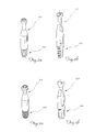
- FIGS 2a,2b and 3a, 3b show two pins/tie-bolts 110,210, respectively, which, in addition to the different threading, also have different lengths of the two top and bottom cylindrical sections and of the middle collar.
- tie-bolts and/or pins generally in a simple, low cost and versatile manner, by means of machining steps which are all cold-machining steps, without the need for subsequent intermediate machine-tool operations, with obvious advantages in terms of reduction of the tooling, production downtime and therefore final costs of the workpiece.
- the top cylindrical part ( Fig. 1c ) with associated inset seat may be obtained in a single pass, omitting step 1b, and in the same way closing of the cylindrical top part ( Fig. 1e ) may be obtained in a single pass 1e, omitting step 1d.
Landscapes
- Engineering & Computer Science (AREA)
- Mechanical Engineering (AREA)
- Forging (AREA)
- Slide Fasteners, Snap Fasteners, And Hook Fasteners (AREA)
- Joining Of Building Structures In Genera (AREA)
Abstract
a) providing a solid workpiece (10a) made of suitable material and having a suitable length in the longitudinal direction and width/diameter in the transverse direction;
wherein the length in the longitudinal direction of the initial workpiece is less than the lenght in the longitudinal direction of the finished pin/tie-bolt;
c) compressing the solid workpiece (10b) inside a second mould (20c) associated with a second punch (30c) with formation of a workpiece (10c) having a length in the longitudinal direction elongated to the final desired size and with an internal longitudinal cavity (11c) having a suitable final depth;
e) compressing in the transverse direction the workpiece (10d) inside a fourth mould (20e) with a longitudinally directed stretching and partial closing of the longitudinal internal cavity with formation of a workpiece (10e) which has a cylindrical top part (10f1) closed to the final desired diameter, a hollow conical connecting collar (13e) with the final size and a hollow cylindrical middle part (10f2) of larger diameter than the cylindrical top part (10f1) and with the final size.
Description
- The present invention relates to a method for producing shaped pins/tie-bolts, particularly, but not exclusively, to be associated with devices for joining two parts arranged at 90° relative to each other.
- It is known, for example in the furnishing goods sector, that there exists the need to assemble furniture such as cupboards, sets of drawers and the like, using flat parts such as side pieces, cross pieces and the like which must be fastened together in a relative right-angled position in order to ensure a final square arrangement of the assembled furniture.
- It is also known that, in order to achieve stable fastening between the various parts, screw/female thread means are widely used, these essentially consisting of a cylindrical tie-bolt, to be concealingly inserted inside a corresponding seat/bushes of one of the two parts and designed to form the part reacting against a grub screw which engages in the transverse direction with said cylindrical member, being screwed onto the female thread of a bush integral with the other part to be joined and thus causing pulling together of the two parts which bear against each other, remaining fastened together.
- Although performing their function, these joining devices have the drawback, however, consisting in the difficulty of producing said pins/tie-bolts which, since they must ensure, in the form of a single body, numerous configurational variations in order to allow correct positioning and mating with the other parts of the joining device, require complicated machining operations and the need for subsequent machine-tool finishing of the semifinished part.
- DE-GM-93 19 728 also discloses a method for forming a solid workpiece which envisages insertion of the said workpiece inside moulds where it is shortened and shaped to the final size of the finished workpiece.
- Although fulfilling its function, this method envisages however the need to start with a workpiece having an initial size larger than its final size, thereby producing a large amount of machining swarf and wasted material.
- The technical problem which is posed, therefore, is to develop a method for the simple and low-cost production of shaped pins/tie-bolts, particularly, but not exclusively suitable for association with a device for joining together two parts, for example the component parts of a piece of furniture or the like.
- In connection with this problem it is also required that this method should allow the production of pins/tie-bolts which are in any case shaped, but sufficiently strong, with a substantial saving in material, and, if necessary, provided with means for operation using normal standardized tools by any user, even without specialized skills.
- These results are achieved according to the present invention by a method according to the characteristic features of Claim 1.
- Further details may be obtained from the following description of a non-limiting example of embodiment of the subject of the present invention provided with reference to the accompanying drawings in which:
- Figs. 1a-1f
- show he various steps for production of a pin/tie-bolt according to the present invention;
- Figs. 2a,2b
- show a side view and partially sectioned view, respectively, of a first embodiment of a pin/tie-bolt according to the present invention; and
- Figs. 3a,3b
- show a side view and partially sectioned view, respectively, of a second embodiment of a pin/tie-bolt according to the present invention.
- As shown in
Fig. 1 and assuming solely for the sake of simplification of the description and without any limitation of meaning a pair of reference axes having, respectively, a longitudinal direction coinciding with the axis of rotation of the tie-bolt and a transverse direction Y-Y, the method for producing a pin/tie-bolt according to the present invention comprises essentially the following steps: - a) providing a
solid workpiece 10a made of suitable material and having a suitable length in the longitudinal direction smaller than the length in the longitudinal direction of the finished pin/tie-bolt and width/diameter in the transverse direction greater than or the same as the width/diameter in the transverse direction of the finished pin/tie-bolt; - b) closing the
solid workpiece 10a inside a first mould 20b with compression of the solid workpiece and simultaneous insertion in the longitudinal direction X-X of a punch 30b; during this step theworkpiece 10a stretches in the longitudinal direction owing to compression of the mould 20b and, encountering the punch 30b, produces a workpiece 10b which is elongated and has an internal cavity 11b extending in the longitudinal direction and of suitable length; during this step thebottom part 12b of the pin/tie-bolt is also compressed and pre-shaped so as to prepare the same for the next processing step; - c) further compressing the workpiece 10b inside a second mould 20c associated with a second punch 30c; during this step the compression produces a workpiece 10c, the top part of which according to the orientational layout in the figures is still cylindrical, and further elongated to the final desired size and with an internal axial cavity 11c having a suitable final depth; during this step shaping of the bottom part 12c of the workpiece 10c is also completed;
- d) compressing the workpiece 10c inside a
third mould 20d; during this step the compression produces a workpiece 10d, the top part of which according to the orientational layout in the figures is deformed so as to reduce partly the diameter of the cylindrical top part with formation of aconical collar 13d connecting together the cylindrical top part 10d1 of smaller diameter and the cylindrical middle part 10d2 of larger diameter; - e) further compressing the workpiece 10d inside a fourth mould 20e; during this finishing and sizing step the compression produces a workpiece 10e, the top part of which is further elongated and which has a cylindrical top part 10f1 closed to the final desired diameter, conical connecting collar with the final size and cylindrical middle part 10f2 of larger diameter than the cylindrical top part 10f1 and with the final size;
- f) final shaping pressing by means of a
punch 30f so as to obtain a workpiece 10f with ahead 14f having an inset, for example cross-like, seat for operation by means of a tool; - g) although not shown a further final step involving rolling of the pin/tie-bolt so as to form a
bottom shank 112 which is self-tapping (Fig. 2a, 2b ) or provided with a thread 212 (Figs. 3a, 3b ) suitable for mating with a corresponding female thread (not shown). - The same
figures 2a,2b and 3a, 3b show two pins/tie-bolts 110,210, respectively, which, in addition to the different threading, also have different lengths of the two top and bottom cylindrical sections and of the middle collar. - It is therefore clear how, with the method according to the invention, it is possible to obtain tie-bolts and/or pins generally in a simple, low cost and versatile manner, by means of machining steps which are all cold-machining steps, without the need for subsequent intermediate machine-tool operations, with obvious advantages in terms of reduction of the tooling, production downtime and therefore final costs of the workpiece.
- It also pointed out how with the method according to the invention it is possible to achieve further economies of scale due to the small initial dimensions of the
initial workpiece 10a which, since the final dimensions are achieved by means of elongation, allows a reduction in the amount of material needed while achieving the same technical, i.e. mechanical strength, characteristics. - It is also envisaged that, if permitted by the corresponding dimensional values, the top cylindrical part (
Fig. 1c ) with associated inset seat may be obtained in a single pass, omitting step 1b, and in the same way closing of the cylindrical top part (Fig. 1e ) may be obtained in a single pass 1e, omitting step 1d. - Although described in connection with certain constructional forms and certain preferred examples of embodiment of the invention, it is understood that the scope of protection of the present patent is defined solely by the following claims.
Claims (6)
- Method for producing a pin/tie-bolt (110;210) extending in the longitudinal direction (X-X), comprising the steps of:a) providing a solid workpiece (10a) made of suitable material and having a suitable length in the longitudinal direction and width/diameter in the transverse direction;e) compressing in the transverse direction the workpiece (10d) inside a fourth mould (20e) with a longitudinally directed stretching and partial closing of the longitudinal internal cavity with formation of a workpiece (10e) which has a cylindrical top part (10f1) closed to the final desired diameter, a conical connecting collar (13e) with the final size and a cylindrical middle part (10f2) of larger diameter than the cylindrical top part (10f1) and with the final size;
characterized in that
the length in the longitudinal direction of the initial solid workpiece (10a) is less than the length in the longitudinal direction of the finished pin/tie-bolt and in that it comprises a preliminary step ofc) compressing the solid workpiece (10b) inside a second mould (20c) associated with a second punch (30c) with formation of a workpiece (10c) having a length in the longitudinal direction elongated to the final desired size and with an internal longitudinal cavity (11c) having a suitable final depth. - Method according to Claim 1, characterized in that the step c) is preceded by a pre-forming step which envisages:b) closing the solid workpiece (10a) inside a first mould (20b) with compression of the solid workpiece and simultaneous insertion in the longitudinal direction (X-X) of a first punch (30b) of suitable length in the axial direction and simultaneous compression and shaping of the bottom part (12b) of the pin/tie-bolt so as to prepare the same for following step c).
- Method according to Claim 1, characterized in that the step e) is preceded by a pre-forming step which envisages:d) compressing the hollow part of the workpiece (10c) leaving the second mould (20c) inside a third mould (20d) so as to form a workpiece (10d), the top part of which has a smaller diameter, a conical collar (13d) connecting together the cylindrical top part (10d1) of smaller diameter and a cylindrical middle part (10d2) of larger diameter;
- Method according to Claim 1, characterized in that it comprises a further step involving:g) rolling the pin/tie-bolt so as to produce a threaded bottom shank (112;212).
- Method according to Claim 1, characterized in that it comprises a further step involving:f) punching the top end in a coaxial direction in order to form a head (14f) with an inset seat suitable for operation by means of a tool;
- Method according to Claim 1, characterized in that the forming steps are cold-forming steps.
Applications Claiming Priority (1)
| Application Number | Priority Date | Filing Date | Title |
|---|---|---|---|
| IT001532A ITMI20091532A1 (en) | 2009-09-04 | 2009-09-04 | PROCEDURE FOR THE PRODUCTION OF A PIN / TIE ROD |
Publications (2)
| Publication Number | Publication Date |
|---|---|
| EP2292347A1 true EP2292347A1 (en) | 2011-03-09 |
| EP2292347B1 EP2292347B1 (en) | 2012-03-14 |
Family
ID=42102609
Family Applications (1)
| Application Number | Title | Priority Date | Filing Date |
|---|---|---|---|
| EP10174806A Active EP2292347B1 (en) | 2009-09-04 | 2010-09-01 | Method for producing a pin/tie-bolt |
Country Status (3)
| Country | Link |
|---|---|
| EP (1) | EP2292347B1 (en) |
| AT (1) | ATE549109T1 (en) |
| IT (1) | ITMI20091532A1 (en) |
Citations (4)
| Publication number | Priority date | Publication date | Assignee | Title |
|---|---|---|---|---|
| JPH01202333A (en) * | 1988-02-05 | 1989-08-15 | Sakamura Kikai Seisakusho:Kk | Manufacture of bolt for robot having conical guide part |
| DE9319728U1 (en) * | 1993-12-22 | 1994-06-16 | Moehling Gmbh & Co | Bolts with a shape in the form of a tip, ball or the like. |
| DE19918196A1 (en) * | 1999-04-22 | 2000-10-26 | Heinrich Hofsaes Gmbh & Co | Adjusting screw for hinges of doors on furniture carcasses has screw portion, narrower neck portion and head and is produced by cold flow press or cold press process |
| JP2008213040A (en) * | 2007-01-22 | 2008-09-18 | Nishio Seimitsu Kk | Hollow-forging member and producing method thereof |
-
2009
- 2009-09-04 IT IT001532A patent/ITMI20091532A1/en unknown
-
2010
- 2010-09-01 AT AT10174806T patent/ATE549109T1/en active
- 2010-09-01 EP EP10174806A patent/EP2292347B1/en active Active
Patent Citations (4)
| Publication number | Priority date | Publication date | Assignee | Title |
|---|---|---|---|---|
| JPH01202333A (en) * | 1988-02-05 | 1989-08-15 | Sakamura Kikai Seisakusho:Kk | Manufacture of bolt for robot having conical guide part |
| DE9319728U1 (en) * | 1993-12-22 | 1994-06-16 | Moehling Gmbh & Co | Bolts with a shape in the form of a tip, ball or the like. |
| DE19918196A1 (en) * | 1999-04-22 | 2000-10-26 | Heinrich Hofsaes Gmbh & Co | Adjusting screw for hinges of doors on furniture carcasses has screw portion, narrower neck portion and head and is produced by cold flow press or cold press process |
| JP2008213040A (en) * | 2007-01-22 | 2008-09-18 | Nishio Seimitsu Kk | Hollow-forging member and producing method thereof |
Also Published As
| Publication number | Publication date |
|---|---|
| EP2292347B1 (en) | 2012-03-14 |
| ITMI20091532A1 (en) | 2011-03-05 |
| ATE549109T1 (en) | 2012-03-15 |
Similar Documents
| Publication | Publication Date | Title |
|---|---|---|
| US20070204668A1 (en) | Method and apparatus for plastic working of hollow rack bar and hollow rack bar | |
| WO2007031052A2 (en) | Hollow shaft and method for the production thereof | |
| CN109108203B (en) | Ball stud cold heading forming die and forming process | |
| KR101930335B1 (en) | Universal joint manufacturing method using the pipe | |
| US20080118301A1 (en) | Ball joint element and method of forming same | |
| KR20110129694A (en) | Input shaft of steering system for vehicles and manufacturing method thereof | |
| KR20110084215A (en) | Method and device for the non-cutting production of an outside thread on hollow metal work pieces | |
| WO2019101881A2 (en) | Connection system for connecting a damping unit of a motor vehicle inside a wheel suspension of said vehicle | |
| JP2010046704A (en) | Method, apparatus and die for manufacturing bolt | |
| KR101808320B1 (en) | L-bolt and its manufacturing method and manufacturing apparatus | |
| EP1477250B1 (en) | Method of making self-piercing nuts | |
| EP2292347B1 (en) | Method for producing a pin/tie-bolt | |
| EP2458131A2 (en) | Method for manufacturing the insertion end of a drill | |
| EP2790850B1 (en) | Method of manufacturing a steering knuckle | |
| CN112719178B (en) | Method for manufacturing bearing pin for welding of vehicle | |
| KR20180029300A (en) | Method for manufacturing long hollow type drive shaft through cold forging precess | |
| DE10100668B4 (en) | Method for producing a ball joint housing | |
| JP5151315B2 (en) | Method for producing hollow molded body | |
| CN109079084B (en) | Cold upsetting and cold forging forming die for connecting fork or joint fork and forming process thereof | |
| WO2008145092A1 (en) | Method for producing hollow shaft base bodies and hollow shaft base body produced according to said method | |
| JP2001276954A (en) | Manufacturing method of housing for ball joint | |
| JPH0890135A (en) | Joint metal tool and manufacture of this half-made product | |
| KR20140016037A (en) | Method for manufacturing flange structure | |
| CN204470310U (en) | Bracelet rod extrusion forming machine | |
| KR101861070B1 (en) | Manufacturing apparatus of insert type axis for hinge |
Legal Events
| Date | Code | Title | Description |
|---|---|---|---|
| PUAI | Public reference made under article 153(3) epc to a published international application that has entered the european phase |
Free format text: ORIGINAL CODE: 0009012 |
|
| AK | Designated contracting states |
Kind code of ref document: A1 Designated state(s): AL AT BE BG CH CY CZ DE DK EE ES FI FR GB GR HR HU IE IS IT LI LT LU LV MC MK MT NL NO PL PT RO SE SI SK SM TR |
|
| AX | Request for extension of the european patent |
Extension state: BA ME RS |
|
| 17P | Request for examination filed |
Effective date: 20110803 |
|
| GRAP | Despatch of communication of intention to grant a patent |
Free format text: ORIGINAL CODE: EPIDOSNIGR1 |
|
| RIC1 | Information provided on ipc code assigned before grant |
Ipc: B21K 1/56 20060101ALI20110909BHEP Ipc: B21K 21/08 20060101ALI20110909BHEP Ipc: B21H 3/02 20060101AFI20110909BHEP Ipc: B21K 1/46 20060101ALI20110909BHEP |
|
| GRAS | Grant fee paid |
Free format text: ORIGINAL CODE: EPIDOSNIGR3 |
|
| GRAA | (expected) grant |
Free format text: ORIGINAL CODE: 0009210 |
|
| AK | Designated contracting states |
Kind code of ref document: B1 Designated state(s): AL AT BE BG CH CY CZ DE DK EE ES FI FR GB GR HR HU IE IS IT LI LT LU LV MC MK MT NL NO PL PT RO SE SI SK SM TR |
|
| REG | Reference to a national code |
Ref country code: GB Ref legal event code: FG4D |
|
| REG | Reference to a national code |
Ref country code: CH Ref legal event code: EP Ref country code: AT Ref legal event code: REF Ref document number: 549109 Country of ref document: AT Kind code of ref document: T Effective date: 20120315 |
|
| REG | Reference to a national code |
Ref country code: IE Ref legal event code: FG4D |
|
| REG | Reference to a national code |
Ref country code: DE Ref legal event code: R096 Ref document number: 602010001042 Country of ref document: DE Effective date: 20120510 |
|
| REG | Reference to a national code |
Ref country code: NL Ref legal event code: VDEP Effective date: 20120314 |
|
| PG25 | Lapsed in a contracting state [announced via postgrant information from national office to epo] |
Ref country code: HR Free format text: LAPSE BECAUSE OF FAILURE TO SUBMIT A TRANSLATION OF THE DESCRIPTION OR TO PAY THE FEE WITHIN THE PRESCRIBED TIME-LIMIT Effective date: 20120314 Ref country code: LT Free format text: LAPSE BECAUSE OF FAILURE TO SUBMIT A TRANSLATION OF THE DESCRIPTION OR TO PAY THE FEE WITHIN THE PRESCRIBED TIME-LIMIT Effective date: 20120314 Ref country code: NO Free format text: LAPSE BECAUSE OF FAILURE TO SUBMIT A TRANSLATION OF THE DESCRIPTION OR TO PAY THE FEE WITHIN THE PRESCRIBED TIME-LIMIT Effective date: 20120614 |
|
| LTIE | Lt: invalidation of european patent or patent extension |
Effective date: 20120314 |
|
| PG25 | Lapsed in a contracting state [announced via postgrant information from national office to epo] |
Ref country code: FI Free format text: LAPSE BECAUSE OF FAILURE TO SUBMIT A TRANSLATION OF THE DESCRIPTION OR TO PAY THE FEE WITHIN THE PRESCRIBED TIME-LIMIT Effective date: 20120314 Ref country code: GR Free format text: LAPSE BECAUSE OF FAILURE TO SUBMIT A TRANSLATION OF THE DESCRIPTION OR TO PAY THE FEE WITHIN THE PRESCRIBED TIME-LIMIT Effective date: 20120615 Ref country code: LV Free format text: LAPSE BECAUSE OF FAILURE TO SUBMIT A TRANSLATION OF THE DESCRIPTION OR TO PAY THE FEE WITHIN THE PRESCRIBED TIME-LIMIT Effective date: 20120314 |
|
| REG | Reference to a national code |
Ref country code: AT Ref legal event code: MK05 Ref document number: 549109 Country of ref document: AT Kind code of ref document: T Effective date: 20120314 |
|
| PG25 | Lapsed in a contracting state [announced via postgrant information from national office to epo] |
Ref country code: CY Free format text: LAPSE BECAUSE OF FAILURE TO SUBMIT A TRANSLATION OF THE DESCRIPTION OR TO PAY THE FEE WITHIN THE PRESCRIBED TIME-LIMIT Effective date: 20120314 |
|
| PG25 | Lapsed in a contracting state [announced via postgrant information from national office to epo] |
Ref country code: CZ Free format text: LAPSE BECAUSE OF FAILURE TO SUBMIT A TRANSLATION OF THE DESCRIPTION OR TO PAY THE FEE WITHIN THE PRESCRIBED TIME-LIMIT Effective date: 20120314 Ref country code: SE Free format text: LAPSE BECAUSE OF FAILURE TO SUBMIT A TRANSLATION OF THE DESCRIPTION OR TO PAY THE FEE WITHIN THE PRESCRIBED TIME-LIMIT Effective date: 20120314 Ref country code: EE Free format text: LAPSE BECAUSE OF FAILURE TO SUBMIT A TRANSLATION OF THE DESCRIPTION OR TO PAY THE FEE WITHIN THE PRESCRIBED TIME-LIMIT Effective date: 20120314 Ref country code: PL Free format text: LAPSE BECAUSE OF FAILURE TO SUBMIT A TRANSLATION OF THE DESCRIPTION OR TO PAY THE FEE WITHIN THE PRESCRIBED TIME-LIMIT Effective date: 20120314 Ref country code: RO Free format text: LAPSE BECAUSE OF FAILURE TO SUBMIT A TRANSLATION OF THE DESCRIPTION OR TO PAY THE FEE WITHIN THE PRESCRIBED TIME-LIMIT Effective date: 20120314 Ref country code: SI Free format text: LAPSE BECAUSE OF FAILURE TO SUBMIT A TRANSLATION OF THE DESCRIPTION OR TO PAY THE FEE WITHIN THE PRESCRIBED TIME-LIMIT Effective date: 20120314 Ref country code: IS Free format text: LAPSE BECAUSE OF FAILURE TO SUBMIT A TRANSLATION OF THE DESCRIPTION OR TO PAY THE FEE WITHIN THE PRESCRIBED TIME-LIMIT Effective date: 20120714 Ref country code: BE Free format text: LAPSE BECAUSE OF FAILURE TO SUBMIT A TRANSLATION OF THE DESCRIPTION OR TO PAY THE FEE WITHIN THE PRESCRIBED TIME-LIMIT Effective date: 20120314 |
|
| PG25 | Lapsed in a contracting state [announced via postgrant information from national office to epo] |
Ref country code: SK Free format text: LAPSE BECAUSE OF FAILURE TO SUBMIT A TRANSLATION OF THE DESCRIPTION OR TO PAY THE FEE WITHIN THE PRESCRIBED TIME-LIMIT Effective date: 20120314 Ref country code: PT Free format text: LAPSE BECAUSE OF FAILURE TO SUBMIT A TRANSLATION OF THE DESCRIPTION OR TO PAY THE FEE WITHIN THE PRESCRIBED TIME-LIMIT Effective date: 20120716 |
|
| PLBE | No opposition filed within time limit |
Free format text: ORIGINAL CODE: 0009261 |
|
| STAA | Information on the status of an ep patent application or granted ep patent |
Free format text: STATUS: NO OPPOSITION FILED WITHIN TIME LIMIT |
|
| PG25 | Lapsed in a contracting state [announced via postgrant information from national office to epo] |
Ref country code: DK Free format text: LAPSE BECAUSE OF FAILURE TO SUBMIT A TRANSLATION OF THE DESCRIPTION OR TO PAY THE FEE WITHIN THE PRESCRIBED TIME-LIMIT Effective date: 20120314 Ref country code: NL Free format text: LAPSE BECAUSE OF FAILURE TO SUBMIT A TRANSLATION OF THE DESCRIPTION OR TO PAY THE FEE WITHIN THE PRESCRIBED TIME-LIMIT Effective date: 20120314 Ref country code: AT Free format text: LAPSE BECAUSE OF FAILURE TO SUBMIT A TRANSLATION OF THE DESCRIPTION OR TO PAY THE FEE WITHIN THE PRESCRIBED TIME-LIMIT Effective date: 20120314 |
|
| 26N | No opposition filed |
Effective date: 20121217 |
|
| REG | Reference to a national code |
Ref country code: DE Ref legal event code: R097 Ref document number: 602010001042 Country of ref document: DE Effective date: 20121217 |
|
| PG25 | Lapsed in a contracting state [announced via postgrant information from national office to epo] |
Ref country code: ES Free format text: LAPSE BECAUSE OF FAILURE TO SUBMIT A TRANSLATION OF THE DESCRIPTION OR TO PAY THE FEE WITHIN THE PRESCRIBED TIME-LIMIT Effective date: 20120625 Ref country code: MC Free format text: LAPSE BECAUSE OF NON-PAYMENT OF DUE FEES Effective date: 20120930 |
|
| REG | Reference to a national code |
Ref country code: IE Ref legal event code: MM4A |
|
| REG | Reference to a national code |
Ref country code: FR Ref legal event code: ST Effective date: 20130531 |
|
| PG25 | Lapsed in a contracting state [announced via postgrant information from national office to epo] |
Ref country code: BG Free format text: LAPSE BECAUSE OF FAILURE TO SUBMIT A TRANSLATION OF THE DESCRIPTION OR TO PAY THE FEE WITHIN THE PRESCRIBED TIME-LIMIT Effective date: 20120614 Ref country code: IE Free format text: LAPSE BECAUSE OF NON-PAYMENT OF DUE FEES Effective date: 20120901 |
|
| PG25 | Lapsed in a contracting state [announced via postgrant information from national office to epo] |
Ref country code: FR Free format text: LAPSE BECAUSE OF NON-PAYMENT OF DUE FEES Effective date: 20121001 |
|
| PG25 | Lapsed in a contracting state [announced via postgrant information from national office to epo] |
Ref country code: AL Free format text: LAPSE BECAUSE OF FAILURE TO SUBMIT A TRANSLATION OF THE DESCRIPTION OR TO PAY THE FEE WITHIN THE PRESCRIBED TIME-LIMIT Effective date: 20120314 Ref country code: MT Free format text: LAPSE BECAUSE OF FAILURE TO SUBMIT A TRANSLATION OF THE DESCRIPTION OR TO PAY THE FEE WITHIN THE PRESCRIBED TIME-LIMIT Effective date: 20120314 |
|
| PG25 | Lapsed in a contracting state [announced via postgrant information from national office to epo] |
Ref country code: TR Free format text: LAPSE BECAUSE OF FAILURE TO SUBMIT A TRANSLATION OF THE DESCRIPTION OR TO PAY THE FEE WITHIN THE PRESCRIBED TIME-LIMIT Effective date: 20120314 |
|
| PG25 | Lapsed in a contracting state [announced via postgrant information from national office to epo] |
Ref country code: SM Free format text: LAPSE BECAUSE OF FAILURE TO SUBMIT A TRANSLATION OF THE DESCRIPTION OR TO PAY THE FEE WITHIN THE PRESCRIBED TIME-LIMIT Effective date: 20120314 Ref country code: LU Free format text: LAPSE BECAUSE OF NON-PAYMENT OF DUE FEES Effective date: 20120901 |
|
| PG25 | Lapsed in a contracting state [announced via postgrant information from national office to epo] |
Ref country code: HU Free format text: LAPSE BECAUSE OF FAILURE TO SUBMIT A TRANSLATION OF THE DESCRIPTION OR TO PAY THE FEE WITHIN THE PRESCRIBED TIME-LIMIT Effective date: 20100901 |
|
| REG | Reference to a national code |
Ref country code: CH Ref legal event code: PL |
|
| GBPC | Gb: european patent ceased through non-payment of renewal fee |
Effective date: 20140901 |
|
| PG25 | Lapsed in a contracting state [announced via postgrant information from national office to epo] |
Ref country code: CH Free format text: LAPSE BECAUSE OF NON-PAYMENT OF DUE FEES Effective date: 20140930 Ref country code: LI Free format text: LAPSE BECAUSE OF NON-PAYMENT OF DUE FEES Effective date: 20140930 Ref country code: MK Free format text: LAPSE BECAUSE OF FAILURE TO SUBMIT A TRANSLATION OF THE DESCRIPTION OR TO PAY THE FEE WITHIN THE PRESCRIBED TIME-LIMIT Effective date: 20120314 Ref country code: GB Free format text: LAPSE BECAUSE OF NON-PAYMENT OF DUE FEES Effective date: 20140901 |
|
| REG | Reference to a national code |
Ref country code: DE Ref legal event code: R081 Ref document number: 602010001042 Country of ref document: DE Owner name: F.LLI MAURI S.P.A., IT Free format text: FORMER OWNER: F.LLI MAURI S.R.L., GARLATE, LECCO, IT |
|
| P01 | Opt-out of the competence of the unified patent court (upc) registered |
Effective date: 20230321 |
|
| PGFP | Annual fee paid to national office [announced via postgrant information from national office to epo] |
Ref country code: DE Payment date: 20230921 Year of fee payment: 14 |
|
| PGFP | Annual fee paid to national office [announced via postgrant information from national office to epo] |
Ref country code: IT Payment date: 20230925 Year of fee payment: 14 |