EP2292311A1 - Non-cylindrical filter elements - Google Patents
Non-cylindrical filter elements Download PDFInfo
- Publication number
- EP2292311A1 EP2292311A1 EP10192390A EP10192390A EP2292311A1 EP 2292311 A1 EP2292311 A1 EP 2292311A1 EP 10192390 A EP10192390 A EP 10192390A EP 10192390 A EP10192390 A EP 10192390A EP 2292311 A1 EP2292311 A1 EP 2292311A1
- Authority
- EP
- European Patent Office
- Prior art keywords
- filter element
- panels
- filtration
- aperture
- element according
- Prior art date
- Legal status (The legal status is an assumption and is not a legal conclusion. Google has not performed a legal analysis and makes no representation as to the accuracy of the status listed.)
- Withdrawn
Links
- 238000001914 filtration Methods 0.000 claims abstract description 63
- 238000007789 sealing Methods 0.000 abstract description 3
- 239000000463 material Substances 0.000 description 34
- 239000012530 fluid Substances 0.000 description 23
- 239000000356 contaminant Substances 0.000 description 10
- 238000010521 absorption reaction Methods 0.000 description 5
- 150000001875 compounds Chemical class 0.000 description 5
- 238000000034 method Methods 0.000 description 5
- -1 polyethylene Polymers 0.000 description 5
- 239000000126 substance Substances 0.000 description 5
- 239000011324 bead Substances 0.000 description 4
- 125000002915 carbonyl group Chemical group [*:2]C([*:1])=O 0.000 description 4
- 230000002378 acidificating effect Effects 0.000 description 3
- 230000000274 adsorptive effect Effects 0.000 description 3
- XAGFODPZIPBFFR-UHFFFAOYSA-N aluminium Chemical compound [Al] XAGFODPZIPBFFR-UHFFFAOYSA-N 0.000 description 3
- 230000007423 decrease Effects 0.000 description 3
- 238000009434 installation Methods 0.000 description 3
- 239000004033 plastic Substances 0.000 description 3
- 229920003023 plastic Polymers 0.000 description 3
- 239000004698 Polyethylene Substances 0.000 description 2
- 239000004743 Polypropylene Substances 0.000 description 2
- 230000002745 absorbent Effects 0.000 description 2
- 239000002250 absorbent Substances 0.000 description 2
- 150000007513 acids Chemical class 0.000 description 2
- 229910052782 aluminium Inorganic materials 0.000 description 2
- 239000000835 fiber Substances 0.000 description 2
- 125000002485 formyl group Chemical class [H]C(*)=O 0.000 description 2
- 239000011521 glass Substances 0.000 description 2
- 238000004519 manufacturing process Methods 0.000 description 2
- 229910052751 metal Inorganic materials 0.000 description 2
- 239000002184 metal Substances 0.000 description 2
- 229920000515 polycarbonate Polymers 0.000 description 2
- 239000004417 polycarbonate Substances 0.000 description 2
- 229920000573 polyethylene Polymers 0.000 description 2
- 239000002861 polymer material Substances 0.000 description 2
- 229920001155 polypropylene Polymers 0.000 description 2
- 239000000758 substrate Substances 0.000 description 2
- 229920000742 Cotton Polymers 0.000 description 1
- JOYRKODLDBILNP-UHFFFAOYSA-N Ethyl urethane Chemical compound CCOC(N)=O JOYRKODLDBILNP-UHFFFAOYSA-N 0.000 description 1
- 239000004831 Hot glue Substances 0.000 description 1
- 229920000297 Rayon Polymers 0.000 description 1
- RTAQQCXQSZGOHL-UHFFFAOYSA-N Titanium Chemical compound [Ti] RTAQQCXQSZGOHL-UHFFFAOYSA-N 0.000 description 1
- 239000002253 acid Substances 0.000 description 1
- 239000011230 binding agent Substances 0.000 description 1
- 229920002678 cellulose Polymers 0.000 description 1
- 239000001913 cellulose Substances 0.000 description 1
- 239000002131 composite material Substances 0.000 description 1
- 238000010276 construction Methods 0.000 description 1
- 230000003247 decreasing effect Effects 0.000 description 1
- 230000001419 dependent effect Effects 0.000 description 1
- 229920001971 elastomer Polymers 0.000 description 1
- 239000011152 fibreglass Substances 0.000 description 1
- 239000002657 fibrous material Substances 0.000 description 1
- 239000006260 foam Substances 0.000 description 1
- 238000007373 indentation Methods 0.000 description 1
- 230000007246 mechanism Effects 0.000 description 1
- 150000002739 metals Chemical class 0.000 description 1
- 239000011368 organic material Substances 0.000 description 1
- 239000002245 particle Substances 0.000 description 1
- 229920000139 polyethylene terephthalate Polymers 0.000 description 1
- 239000005020 polyethylene terephthalate Substances 0.000 description 1
- 229920001296 polysiloxane Polymers 0.000 description 1
- 229920002635 polyurethane Polymers 0.000 description 1
- 239000004814 polyurethane Substances 0.000 description 1
- 230000000717 retained effect Effects 0.000 description 1
- 239000005060 rubber Substances 0.000 description 1
- 125000006850 spacer group Chemical group 0.000 description 1
- 239000010936 titanium Substances 0.000 description 1
- 229910052719 titanium Inorganic materials 0.000 description 1
- 230000007704 transition Effects 0.000 description 1
- 150000003673 urethanes Chemical class 0.000 description 1
Images



Classifications
-
- B—PERFORMING OPERATIONS; TRANSPORTING
- B01—PHYSICAL OR CHEMICAL PROCESSES OR APPARATUS IN GENERAL
- B01D—SEPARATION
- B01D46/00—Filters or filtering processes specially modified for separating dispersed particles from gases or vapours
- B01D46/52—Particle separators, e.g. dust precipitators, using filters embodying folded corrugated or wound sheet material
- B01D46/521—Particle separators, e.g. dust precipitators, using filters embodying folded corrugated or wound sheet material using folded, pleated material
-
- B—PERFORMING OPERATIONS; TRANSPORTING
- B01—PHYSICAL OR CHEMICAL PROCESSES OR APPARATUS IN GENERAL
- B01D—SEPARATION
- B01D39/00—Filtering material for liquid or gaseous fluids
- B01D39/14—Other self-supporting filtering material ; Other filtering material
- B01D39/16—Other self-supporting filtering material ; Other filtering material of organic material, e.g. synthetic fibres
- B01D39/1607—Other self-supporting filtering material ; Other filtering material of organic material, e.g. synthetic fibres the material being fibrous
-
- B—PERFORMING OPERATIONS; TRANSPORTING
- B01—PHYSICAL OR CHEMICAL PROCESSES OR APPARATUS IN GENERAL
- B01D—SEPARATION
- B01D46/00—Filters or filtering processes specially modified for separating dispersed particles from gases or vapours
- B01D46/0002—Casings; Housings; Frame constructions
- B01D46/0005—Mounting of filtering elements within casings, housings or frames
-
- B—PERFORMING OPERATIONS; TRANSPORTING
- B01—PHYSICAL OR CHEMICAL PROCESSES OR APPARATUS IN GENERAL
- B01D—SEPARATION
- B01D46/00—Filters or filtering processes specially modified for separating dispersed particles from gases or vapours
- B01D46/0027—Filters or filtering processes specially modified for separating dispersed particles from gases or vapours with additional separating or treating functions
- B01D46/0036—Filters or filtering processes specially modified for separating dispersed particles from gases or vapours with additional separating or treating functions by adsorption or absorption
-
- B—PERFORMING OPERATIONS; TRANSPORTING
- B01—PHYSICAL OR CHEMICAL PROCESSES OR APPARATUS IN GENERAL
- B01D—SEPARATION
- B01D46/00—Filters or filtering processes specially modified for separating dispersed particles from gases or vapours
- B01D46/10—Particle separators, e.g. dust precipitators, using filter plates, sheets or pads having plane surfaces
-
- B—PERFORMING OPERATIONS; TRANSPORTING
- B01—PHYSICAL OR CHEMICAL PROCESSES OR APPARATUS IN GENERAL
- B01D—SEPARATION
- B01D46/00—Filters or filtering processes specially modified for separating dispersed particles from gases or vapours
- B01D46/56—Filters or filtering processes specially modified for separating dispersed particles from gases or vapours with multiple filtering elements, characterised by their mutual disposition
- B01D46/58—Filters or filtering processes specially modified for separating dispersed particles from gases or vapours with multiple filtering elements, characterised by their mutual disposition connected in parallel
-
- B—PERFORMING OPERATIONS; TRANSPORTING
- B01—PHYSICAL OR CHEMICAL PROCESSES OR APPARATUS IN GENERAL
- B01D—SEPARATION
- B01D2271/00—Sealings for filters specially adapted for separating dispersed particles from gases or vapours
- B01D2271/02—Gaskets, sealings
-
- B—PERFORMING OPERATIONS; TRANSPORTING
- B01—PHYSICAL OR CHEMICAL PROCESSES OR APPARATUS IN GENERAL
- B01D—SEPARATION
- B01D2271/00—Sealings for filters specially adapted for separating dispersed particles from gases or vapours
- B01D2271/02—Gaskets, sealings
- B01D2271/027—Radial sealings
-
- B—PERFORMING OPERATIONS; TRANSPORTING
- B01—PHYSICAL OR CHEMICAL PROCESSES OR APPARATUS IN GENERAL
- B01D—SEPARATION
- B01D2275/00—Filter media structures for filters specially adapted for separating dispersed particles from gases or vapours
- B01D2275/10—Multiple layers
-
- B—PERFORMING OPERATIONS; TRANSPORTING
- B01—PHYSICAL OR CHEMICAL PROCESSES OR APPARATUS IN GENERAL
- B01D—SEPARATION
- B01D2275/00—Filter media structures for filters specially adapted for separating dispersed particles from gases or vapours
- B01D2275/20—Shape of filtering material
- B01D2275/206—Special forms, e.g. adapted to a certain housing
Definitions
- the present invention relates to a fluid filter for removing contaminants from a gaseous stream, such as an air stream.
- Filter elements are used in many industries to remove airborne contaminants to protect people, the environment, and often, a critical manufacturing process or the products that are manufactured by the process.
- Non-cylindrical filter elements are provided.
- the filter elements have at least two flat or planar filtration panels. Fluid, such as air, to be filtered enters the filter element through the panels, preferably through each of the panels.
- An outlet aperture is provided, which has generally the same shape as the cross-sectional shape of the filter.
- a filter element having three filter elements will be generally triangular in shape and have a generally triangular outlet aperture.
- the design of the present filter element can be such that both axial and radial seals are formed between the outlet aperture and any outlet duct or piping.
- the filter element can include an integrally molded outlet flange or collar for connecting to an outlet duct.
- the filter element of the present disclosure by having a non-circular outlet aperture, increases the outlet area to thus decrease outlet velocity and decrease pressure drop.
- the non-circular cross-section limits the possible orientations for adjoining ductwork, which is desired for some installations; a circular outlet has infinite orientations, which may be a non-preferred configuration for some installations.
- Filter element 10 is a fluid filter; that is, filter element 10 filters out or removes contaminants from a fluid stream.
- filter element 10 is a gas filter, configured for removal of contaminants from a gas stream.
- the gas being filtered is air.
- Filter element 10 is particularly suitable for use in an aircraft or other lightweight vehicle, for filtering cabin air. In a passenger aircraft, filter element 10 would generally be located in a cargo hold, below the passenger cabin.
- filter element 10 in many embodiments, is removably positioned in a housing, duct, or other structure.
- the housing, duct or other structure may or may not complete enclose or envelope filter element 10.
- Filter element 10 has a first end 12 and an opposite second end 14.
- Filter element includes filtration panels 16 and support structure 18, which will be described below. Together, panels 16 and support structure 18, between first end 12 and second end 14, define a filter interior 15. Panels 16 provide fluid access into and out from interior 15. Second end 14 includes an aperture 20, which provides fluid access to and from interior 15. In FIGS. 2 , 4A and 4B , a duct 44 is attached to aperture 20. In the preferred configuration, panels 16 provide fluid access into interior 15, and are thus the inlet into interior 15 of filter 10. Thus, fluid to be filtered passes through panels 16 and panels 16 provide filtration. In line with panels 16 being the inlet into filter 10, aperture 20 provides access out from interior 15, and thus is the outlet from interior 15 of filter 10.
- Panels 16 are radially positioned in relation to interior 15, and aperture 20 is axially positioned in relation to interior 15. With such a configuration, the fluid being filtered changes direction, e.g., turns, when moving from panels 16 (e.g., the inlet) to aperture 20 (e.g., the outlet). Generally, no air or other fluid passes out from interior 15 through panels 16.
- Filter element 10 is generally a non-cylindrical element.
- filter element 10 is a three-sided filter element 11, composed of three panels 16, which are generally flat or planar.
- generally flat or “generally planar”
- the panel may not be completely flat or planar (i.e., having a surface angle of 0 degrees), but may include a slight dip, indentation variation, bend, or the like on its surface or structure; overall, the overall surface angle of a "generally planar” or “generally flat” panel, from end-to-end, is no more than 10 degrees, preferably no more than 5 degrees.
- filter element 10 has no rounded or curved surfaces, e.g., panels 16, that provide filtration.
- Filter element 10 includes at least two filtration portions or panels 16; preferably filter element 10 includes at least three filtration panels 16. For three-sided filter element 11, panels 16 are indicated as first panel 16a, second panel 16b, and third panel 16b. It is understood that filter element 10 could have any number of panels 16, however, as the number of panels 16 increases the cost of designing and assembling such a filter 10 generally increases, thus, less panels 16 are preferred. Preferred numbers of panels 16 include three, four, six, and eight.
- the at least two panels 16 are positioned angled to other or they may be opposite each other.
- the at least two panels 16 may be evenly spaced.
- a filter element having two panels 16 may have the panels 16 opposite to and parallel to each other.
- filter element 10 has three panels 16a, 16b, 16c spaced apart approximately 120 degrees.
- a filter element having two panels 16 may have panels 16 angled with respect to each other, for example, at an angle of 90 degrees. It is understood that other degrees, other than 0 degrees (i.e., having the panels 16 planar to or co-planar with each other), are suitable.
- each of panels 16a, 16b, 16c is the same size, shape and filtration material, although it is not necessary that all panels have the same size, shape and/or filtration material.
- Panels 16 are planar or flat; that is, they are not rounded or curved. The planar or flat characteristic is due to the rigid material used for panels 16. In future embodiments, it may be possible to provide non-planar or curved panels, however, the present application is directed to using planar, non-curved filtration panels 16.
- Panels 16 are held together by a support structure 18, which can be any combination of suitable frames, pieces, and materials to provide support to panels 16 and define interior 15 and aperture 20.
- suitable materials for any portion of support structure 18 include metals (e.g., aluminum, titanium), polymeric or plastic materials (e.g., polyethylene, polyethylene terephthalate, polypropylene, polycarbonate, urethane or polyurethane), composite materials, or any combinations thereof.
- support structure 18 includes aluminum metal bent as a frame to support panels 16 and a hard polymer material molded to engulf the metal frame and seal interior 15 from the exterior of element 10.
- support structure 18 includes hard plastic molded as a frame to support panels 16 and a soft polymer material molded to engulf the hard plastic frame and seal interior 15 from the exterior of element 10.
- Support structure 18 may include details and features to attach filter 10 to mounting brackets or other supporting structures.
- Panels 16 of filter element 10 filter particulate and chemical contaminants from the fluid passing therethrough.
- Panels 16 may include a single feature or layer that accomplishes both chemical and particulate removal from the fluid passing therethrough. However, as in a preferred embodiment, panels 16 include multiple features or layers. Referring to FIG. 4A , panel 16c is illustrated having four layers, first media layer 22, second media layer 24, third medial layer 26 and fourth media layer 28.
- a first example of a suitable layer, for any of media layers 22, 24, 26, 28 is a low pressure drop, rigid article having a plurality of passages therethrough, the passages having surfaces with adsorptive material. Fluid passes through the passages following the direction of the passage, which is generally in a straight line. Contaminants present in the fluid are adsorbed, absorbed, trapped, retained, reacted, or otherwise removed from the fluid by the adsorptive material.
- the rigid article can be configured for removal of specific contaminants.
- the article can be designed for the removal of acidic materials, of basic materials, organic materials, or any combination thereof.
- a suitable layer for any of media layers 22, 24, 26, 28 is a low pressure drop fibrous article having a plurality of passages therethrough, the fibrous material having been impregnated with various materials to adsorb, absorb, or react with contaminants.
- Pending U.S. patent application having serial number 10/928,776 (Dallas et al.), filed Aug. 27, 2004 entitled “Acidic Impregnated Filter Element, and Methods” provides impregnated porous elements specifically designed for the removal of basic or alkaline compounds; this application is incorporated herein by reference.
- Pending U.S. patent application having serial number 10/927,708 (Dallas et al.), filed Aug.
- a third example for a suitable layer for any of media layers 22, 24, 26, 28 is a fibrous or particulate filtration layer.
- Suitable examples of a particulate layer include mats of randomly placed non-woven fibers, thin layers of conventional filtration media, and pleated conventional filtration media.
- a preferred filtration media to use is HEPA media.
- HEPA filters are known in the art of filters as "high-efficiency particulate air" filters.
- HEPA media is the media of the filter that provides the filtration efficiency. HEPA media has a minimum efficiency of 99.97% removal when tested with essentially monodispersed 0.3 micron particles.
- the media may be any suitable HEPA media and may be made from cellulose, polymeric materials (e.g., viscose, polypropylene, polycarbonate, etc.), glass or fiberglass, or natural materials (e.g., cotton). Other HEPA media materials are known. Microfibrous glass is a preferred material for HEPA media.
- a suitable HEPA media for aircraft applications is that commercially available as H&V "HB-7633".
- any of the fibrous or media materials may be electrostatically treated and/or include one or more layers of material.
- One or more layers of fine fiber such as taught by U.S. Patent No. 6,673,136 (Gillingham et al. ), may be included.
- first media layer 22 is a pleated HEPA filter element configured for particulate removal
- second media layer 24 is a rigid media having impregnated absorbent materials (such as taught by U.S. Patent No. 6,645,271 )
- third media layer 26 is a rigid media having impregnated absorbent material (such as taught by U.S. Patent No. 6,645,271 )
- fourth media layer 28 is a rigid media configured for carbonyl-containing compound removal, particularly for aldehyde removal (such as taught by U.S. patent application no. 10/947,732 ).
- fluid to be filtered would first pass through the HEPA filter, then through two rigid layers to remove acids and bases, and then through a layer to remove aldehydes.
- HEPA filter HEPA filter
- this is an exemplary configuration for the media layers, and that other arrangements are suitable.
- none, one, two, or any number of the media layers may be rigid and/or impregnated, or the various layers may be impregnated with different materials and/or arranged to provide a different path through the layers.
- the filtered fluid such as air, arrives in interior 15 of filter element 10. From interior 15, the fluid exits filter element 10 via aperture 20.
- Aperture 20 is present at second end 14 of element 10.
- Aperture 20 includes an outlet aperture 30 that provides access into and out from interior 15.
- outlet aperture 30 is a three-sided outlet aperture 31, as will be further described below.
- Surrounding aperture 30 is an outlet collar or flange 32.
- Collar 32 preferably has a circular outer perimeter, for reasons which will be described later.
- Outlet aperture 30 preferably has the same number of sides as there are number of panels 16.
- the aperture is a three-sided outlet aperture 31.
- Aperture 31, and any non-round aperture 30, need not be a true polygon, but can include rounded or curved sides and/or corners. See for example, FIG. 3A .
- Aperture 31 has a general triangular shaped, but with rounded angles or corners and curved sides; aperture 31 could be referred to as having a tri-oval or a tri-lobal shape.
- outlet aperture 30 is selected to correspond to the overall shape of filter element 10, which is dependent on the number of panels 16.
- Outlet aperture 30 preferably follows the same general shape as interior 15, formed by panels 16 and support structure 18. Having outlet aperture 30 generally correspond to the shape of interior 15 allows a larger outlet aperture area than if a circular outlet were used. For example, for aperture 31, the three corners extend farther out than would a circular outlet, thus obtaining more outlet area. Increased outlet area is desired as it decreases the velocity of the exiting fluid, thus decreasing pressure losses.
- Collar 32 is configured to receive duct 44 (see FIGS. 2 and 4A ) and provide a leak-free seal therebetween.
- the particular configuration of collar 32 provides both axial and radial sealing to duct 44.
- collar 32 includes an inner perimeter surface 34, a stop or longitudinal surface 36, a chamfered edge 38 on the inner surface 34, and outer perimeter surface 40 opposite inner surface 34, and a retaining lip 42 at outer surface 40.
- Inner surface 34, stop 36 and chambered edge 38 have the same general shape as aperture 30, which in the illustrated embodiment, is aperture 31.
- Outer perimeter surface 40 and retaining lip 42 have a generally circular shape.
- Collar 32 can be formed, typically molded, together with support structure 18; collar 32 may be integral with support structure 18. Such a configuration eliminates the need for a separate flange to be attached to filter element 10.
- duct 44 is configured to fit within collar 32 and specifically, within inner perimeter surface 34.
- Duct 44 is specifically configured to fit with the tri-oval or tri-lobal shape of aperture 31.
- Duct 44 includes a transition region 46, which changes from tri-oval or tri-lobal to circular, thus allowing filter element 11 to be connected to circular ductwork.
- duct 44 is slid into collar 30, facilitated by chamfered surface 38.
- Duct 44 is pushed in to seal against both inner surface 34 and stop 36.
- a radial seal is formed between duct 44 and inner surface 34 and an axial seal is formed between duct 44 and stop 36.
- a band clamp 50 (seen in FIG. 4B ) is used to tighten against collar 30 and duct 44.
- Band clamp 50 is positioned on collar 32 against outer surface 40, between retaining lip 42 of collar 32 and bead 48 on duct 44. Positioning between lip 42 and bead 48 improves the stability of clamp 50 and reduces the chance of it pulling off.
- collar 32 has a circular outer perimeter.
- band clamp 50 When band clamp 50 is positioned on collar 32 behind retaining lip 42, band clamp 50 contacts collar 32 continuously around the perimeter and, thus, the pressure exerted by band clamp 50 is a uniformly distributed load around collar 32 and duct 44.
- filter element 10 according to the present invention is illustrated.
- the particular embodiment of filter element 10 of these figures is filter element 100. It is to be understood that any of the features from filter element 10 could be used for filter element 100, in any combination, and vice versa.
- Filter element 100 has a first end 112 and an opposite second end 114.
- Filter element includes filtration panels 116 and support structure 118. Together, panels 116 and support structure 118, between first end 112 and second end 114, define a filter interior 115. Panels 116 provide fluid access into and out from interior 115, thus providing an inlet into interior 115. Second end 114 includes an aperture 120, which provides fluid access to and from interior 115, and thus providing and outlet from interior 115.
- first end 112 includes indicia thereon; it is understood that any filter element embodiment may include indicia, or, no indicia may be present. Such indicia can be used to identify the manufacturer of filter element 100, or to convey, for example, installation instructions.
- Filter element 100 is a non-cylindrical element, particularly, a three-sided filter element composed of three planar or flat panels 116. Filter element 100 has no rounded or curved surfaces that provide filtration.
- Filter element 100 includes at least two filtration portions or panels 116; in this embodiment, filter element 100 has three panels 116, which are indicated as first panel 116a, second panel 116b, and third panel 116b.
- each of panels 116a, 116b, 116c is the same size, shape and filtration material, although it is not necessary that all panels have the same size, shape and/or filtration material.
- Panels 116 are preferably planar or flat; that is, they are not rounded or curved.
- Panels 116 filter particulate and chemical contaminants from the fluid passing therethrough.
- Panels 116 may include a single feature or layer that accomplishes both chemical and particulate removal from the fluid passing therethrough.
- each panel 116 of this embodiment is composed of multiple layers, similar to filter element 11. The same materials suitable for panels 16 are suitable for panels 116.
- aperture 120 of filter element 100 provides access into and out from interior 115.
- aperture 120 is a three-sided outlet aperture, as will be further described below, defined by structure 122, which is similar to collar 32 of filter element 11 in many aspects.
- Structure 122 includes an outer surface 124 and an inner perimeter surface 134.
- outer surface 124 and inner surface 134 of structure 122 have generally the same shape, i.e., they are both generally triangular, unlike for filter element 11 wherein outer surface 40 is generally circular and inner surface 34 is generally triangular.
- Aperture 120 and structure 122 have the same number of sides as there are number of panels 116, i.e., three for this embodiment. Aperture 120 and structure 122 have a generally triangular shape, but with rounded angles or corners. The shape of aperture 120, and in this embodiment, of structure 122, is selected to correspond to the overall shape of filter element 100.
- structure 122 is similar to collar 32 of filter element 11, except that, for example, structure 122 does not extend away from structure 118 in the same manner that collar 32 extends away from structure 18.
- Structure 122 includes a channel, trough, or other recessed area which retains a seal 136.
- Structure 122 in particular seal 136, has a low or no-clearance; that is, structure 122 extends no more than about 1 cm, preferably no more than about 0.5 cm, past support structure 118 of filter element 100. In preferred embodiments, structure 122 is flush with or recessed in toward end 114.
- filter element 100 will be operably sealed against bracket 150 at structure 122, in particular at seal 136, to provide a leak-free seal.
- Bracket 150 includes a protrusion 155 extending toward filter element 100.
- Protrusion 155 can be a radiused or sloped bead, and have a height of at least about 0.1 cm (1mm), or at least about 0.25 cm.
- filter element 100 Prior to use, filter element 100 is slid into placed against bracket 150. Having structure 122 with a low or no-clearance facilitates sliding filter element 100 into its position, with minimal clearance needed between bracket 150 and filter element 100.
- seal 136 When properly seated, filter element 100, via seal 136, forms an axial seal with bracket 150. Depending on the configuration of protrusion 155, a radial seal may also be formed. Seal 136 is sufficiently deformable, flexible and/or resilient to allow protrusion 155 to embed into seal 136; seal 136 is generally a low-durometer material. Examples of suitable material for seal 136 include urethanes, polyethylenes, silicone, rubbers, and other similar materials. Seal 136 may be, for example, a rolled seal, may be formed-in-place, such as by a one-component or multiple-component foam or gel that is poured into place. The engagement of seal 136 with protrusion 155 and bracket 150 should be a continuous seal, with no breaks.
- Filter element 100 may be seated in a generally horizontal position, as illustrated in the figures, with the outlet being generally horizontal out from interior 115, or, filter element 100 may be seated in a generally vertical position, with the outlet being generally vertical above or below interior 115.
- Filter element 100 includes three mounting elements 140 and three mounting elements 145.
- mounting elements 140 function both as handles, to facilitate moving and lifting of filter element 100, and as mounting mechanisms, to mount and lock filter element in a desired position, for example, for use.
- Mounting elements 145 also mount and lock filter element 100 in the desired position. It is not necessary that all three mounting elements 140 and three mounting elements 145 are used; this will depend on the housing, duct, or other structure to which filter element 100 is mounted. For example, only two mounting elements 140 together with all three mounting elements 145 may be used. Other configurations of mounting elements can also be used.
- mounting elements 140 may be used for mounting of element 100 and a separate structure can be used to facilitate moving and lifting of the filter element, or, mounting elements 140 may be used solely as handles.
- Filter element 10 filter element 100 Panel size 17.5 x 25 inches # of panels 16 3 3 panel thickness 4.6 inches # layers in panel 16 4 layer 1 pleated HEPA filter (having a thickness of about 1.5 inches) with hot melt adhesive spacer beads between the pleats pleated HEPA filter (having a thickness of about 1.5 inches) layer 2 rigid absorption filtration media layer (having a thickness of about 1.04 inches) layer 3 rigid absorption filtration media layer (having a thickness of about 1.04 inches) layer 4 rigid absorption filtration media layer (having a thickness of about 1.04 inches) A 25.31 inches 25.96 inch B 22.75 inches 22.53 inches c 17.00 inches 17.14 inches D 3.80 inch radius E 2.75 inch radius F 16.00 inch radius G 15.25 inch radius H 15.00 inch diameter I 25.00 inches 25.00 inches J 11.56 inches
- the widest dimension, in one direction is about 26.3 inches, and, in another direction, is about 22.8 inches.
- collar 32 extend pasts panels 16 by about 2 inches.
- the approximate diameter of aperture 31 is 15.25 inches, with the corners of aperture 31 being radiused to 2.75 inches.
- Such an outlet aperture has an area of about 94.7 square inches; a comparable circular outlet would have an area of about 38.5 square inches.
- Circumscribing aperture 31 is an outer surface 40, which follows the shape of aperture 31. Outer surface 40 has an approximate diameter of 10 inches with the corners being radiused to 3.5 inches.
- said filter element includes:
- the support structure may define the non-circular aperture.
- the non-circular aperture may have an inner perimeter surface and an outer perimeter surface.
- said filter element may comprise:
- said filter element, the inner perimeter surface may comprise:
- the non-circular aperture may comprise a seal.
- the seal may be within a channel.
- the at least two generally planar filtration panels may consist of three generally planar filtration panels; and the non-circular aperture is a tri-oval or tri-lobal aperture.
- the at least two generally planar filtration panels may comprise a multiple layers of filtration material.
- the multiple layers of filtration material may include at least one layer of HEPA media.
- the multiple layers of filtration materials may include at least one layer of rigid filtration material configured for absorption of a chemical contaminant.
- the multiple layers of filtration materials may include at least two layers of rigid filtration material configured for absorption, the at least two layers being different.
- a filter element may comprise:
- the non-circular aperture may be a tri-oval or tri-lobal aperture.
- the seal may comprise a seal recessed in a channel.
Landscapes
- Chemical & Material Sciences (AREA)
- Chemical Kinetics & Catalysis (AREA)
- Filtering Of Dispersed Particles In Gases (AREA)
- Filters And Equalizers (AREA)
- Thermistors And Varistors (AREA)
- Piezo-Electric Or Mechanical Vibrators, Or Delay Or Filter Circuits (AREA)
Abstract
Description
- This application is being filed on 3 February 2006, as a PCT International Patent application in the name of Donaldson Company, Inc., a U.S. national corporation, applicant for the designation of all countries except the US, and Jarren B. Mills, Daniel E. Adamek, and Richard P. DeJong, all citizens of the U.S., and claims priority to
U.S. Provisional Application Serial Number 60/650,019 filed February 4, 2005 U.S. Provisional Application Serial Number 60/733,978 filed November 3, 2005 - The present invention relates to a fluid filter for removing contaminants from a gaseous stream, such as an air stream.
- Filter elements are used in many industries to remove airborne contaminants to protect people, the environment, and often, a critical manufacturing process or the products that are manufactured by the process.
- There is always a need to design different filter elements.
- Non-cylindrical filter elements are provided. Preferably, the filter elements have at least two flat or planar filtration panels. Fluid, such as air, to be filtered enters the filter element through the panels, preferably through each of the panels. An outlet aperture is provided, which has generally the same shape as the cross-sectional shape of the filter. A filter element having three filter elements will be generally triangular in shape and have a generally triangular outlet aperture.
- The design of the present filter element can be such that both axial and radial seals are formed between the outlet aperture and any outlet duct or piping. The filter element can include an integrally molded outlet flange or collar for connecting to an outlet duct.
- Various problems are solved by the design of the present disclosure. The filter element of the present disclosure, by having a non-circular outlet aperture, increases the outlet area to thus decrease outlet velocity and decrease pressure drop. The non-circular cross-section limits the possible orientations for adjoining ductwork, which is desired for some installations; a circular outlet has infinite orientations, which may be a non-preferred configuration for some installations.
- Referring now to the drawings, wherein like reference numerals and letters indicate corresponding structure throughout the several views:
-
FIG. 1 is a perspective view of a filter element according to the present invention; -
FIG. 2 a perspective view of the filter element ofFIG. 1 operably connected to an outlet duct; -
FIG. 3A is an end view of the filter element ofFIG. 1 ; -
FIG. 3B is similar toFIG. 3A ; -
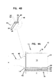
FIG. 4A is a cross-sectional view of the filter element taken along line 4-4 ofFIG. 3A , the filter element including the outlet duct thereon; -
FIG. 4B is an enlarged section of a portion ofFIG. 4A detailing the outlet seal; -
FIG. 5 is a perspective view of a second embodiment of a filter element according to the present invention; -
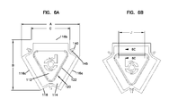
FIG. 6A is an end view of the filter element ofFIG. 5 ; -
FIG. 6B is similar toFIG. 6A ; and -
FIG. 6C is a cross-sectional view of a portion of the filter element ofFIG. 6A taken along line 6-6. - Referring now to the Figures, a filter element according to the present invention is shown at 10 in
FIGS. 1 through 4B .Filter element 10 is a fluid filter; that is,filter element 10 filters out or removes contaminants from a fluid stream. In many embodiments,filter element 10 is a gas filter, configured for removal of contaminants from a gas stream. In most embodiments, the gas being filtered is air.Filter element 10 is particularly suitable for use in an aircraft or other lightweight vehicle, for filtering cabin air. In a passenger aircraft,filter element 10 would generally be located in a cargo hold, below the passenger cabin. - In use,
filter element 10, in many embodiments, is removably positioned in a housing, duct, or other structure. The housing, duct or other structure may or may not complete enclose orenvelope filter element 10. -
Filter element 10 has afirst end 12 and an oppositesecond end 14. Filter element includesfiltration panels 16 andsupport structure 18, which will be described below. Together,panels 16 andsupport structure 18, betweenfirst end 12 andsecond end 14, define afilter interior 15.Panels 16 provide fluid access into and out frominterior 15.Second end 14 includes anaperture 20, which provides fluid access to and frominterior 15. InFIGS. 2 ,4A and 4B , aduct 44 is attached toaperture 20. In the preferred configuration,panels 16 provide fluid access intointerior 15, and are thus the inlet intointerior 15 offilter 10. Thus, fluid to be filtered passes throughpanels 16 andpanels 16 provide filtration. In line withpanels 16 being the inlet intofilter 10,aperture 20 provides access out frominterior 15, and thus is the outlet frominterior 15 offilter 10.Panels 16 are radially positioned in relation tointerior 15, andaperture 20 is axially positioned in relation tointerior 15. With such a configuration, the fluid being filtered changes direction, e.g., turns, when moving from panels 16 (e.g., the inlet) to aperture 20 (e.g., the outlet). Generally, no air or other fluid passes out frominterior 15 throughpanels 16. -
Filter element 10 is generally a non-cylindrical element. In the particular embodiment illustrated,filter element 10 is a three-sided filter element 11, composed of threepanels 16, which are generally flat or planar. By the terms "generally flat" or "generally planar", what is intended it that the panel may not be completely flat or planar (i.e., having a surface angle of 0 degrees), but may include a slight dip, indentation variation, bend, or the like on its surface or structure; overall, the overall surface angle of a "generally planar" or "generally flat" panel, from end-to-end, is no more than 10 degrees, preferably no more than 5 degrees. In some embodiments,filter element 10 has no rounded or curved surfaces, e.g.,panels 16, that provide filtration. -
Filter element 10 includes at least two filtration portions orpanels 16; preferably filterelement 10 includes at least threefiltration panels 16. For three-sided filter element 11,panels 16 are indicated asfirst panel 16a,second panel 16b, andthird panel 16b. It is understood thatfilter element 10 could have any number ofpanels 16, however, as the number ofpanels 16 increases the cost of designing and assembling such afilter 10 generally increases, thus,less panels 16 are preferred. Preferred numbers ofpanels 16 include three, four, six, and eight. - The at least two
panels 16 are positioned angled to other or they may be opposite each other. The at least twopanels 16 may be evenly spaced. For example, a filter element having twopanels 16 may have thepanels 16 opposite to and parallel to each other. As another example,filter element 10 has threepanels panels 16 may havepanels 16 angled with respect to each other, for example, at an angle of 90 degrees. It is understood that other degrees, other than 0 degrees (i.e., having thepanels 16 planar to or co-planar with each other), are suitable. - Preferably, each of
panels Panels 16 are planar or flat; that is, they are not rounded or curved. The planar or flat characteristic is due to the rigid material used forpanels 16. In future embodiments, it may be possible to provide non-planar or curved panels, however, the present application is directed to using planar,non-curved filtration panels 16. -
Panels 16 are held together by asupport structure 18, which can be any combination of suitable frames, pieces, and materials to provide support topanels 16 and define interior 15 andaperture 20. Examples of suitable materials for any portion ofsupport structure 18 include metals (e.g., aluminum, titanium), polymeric or plastic materials (e.g., polyethylene, polyethylene terephthalate, polypropylene, polycarbonate, urethane or polyurethane), composite materials, or any combinations thereof. - In one embodiment,
support structure 18 includes aluminum metal bent as a frame to supportpanels 16 and a hard polymer material molded to engulf the metal frame and seal interior 15 from the exterior ofelement 10. In another embodiment,support structure 18 includes hard plastic molded as a frame to supportpanels 16 and a soft polymer material molded to engulf the hard plastic frame and seal interior 15 from the exterior ofelement 10.Support structure 18 may include details and features to attachfilter 10 to mounting brackets or other supporting structures. -
Panels 16 of filter element 10 (or, for the specific embodiment illustrated,panels Panels 16 may include a single feature or layer that accomplishes both chemical and particulate removal from the fluid passing therethrough. However, as in a preferred embodiment,panels 16 include multiple features or layers. Referring toFIG. 4A ,panel 16c is illustrated having four layers,first media layer 22,second media layer 24, thirdmedial layer 26 andfourth media layer 28. - A first example of a suitable layer, for any of
media layers - Examples of such rigid articles are taught in
U.S. Patent No. 6,645,271 (Sequin et al. ), the entire disclosure of which is incorporated herein by reference. PendingU.S. patent application having serial number 10/947,732 (Ding et al.), filed Sept. 23, 2004 - Another example of a suitable layer for any of
media layers U.S. patent application having serial number 10/928,776 (Dallas et al.), filed Aug. 27, 2004U.S. patent application having serial number 10/927,708 (Dallas et al.), filed Aug. 27, 2004U.S. patent application having entitled " Impregnated Filter Element, and Methods" provides impregnated porous elements specifically designed for the removal of carbonyl-containing compounds; this application is incorporated herein by reference. Additional details regarding removal of alkaline materials, acidic materials, carbonyl-containing compounds, and organics, are provided in pendingserial number 11/016,013 (Ding et al.), filed Dec. 17, 2004PCT application having serial number US05/30577, filed August 25, 2005 . - A third example for a suitable layer for any of
media layers - HEPA filters are known in the art of filters as "high-efficiency particulate air" filters. HEPA media is the media of the filter that provides the filtration efficiency. HEPA media has a minimum efficiency of 99.97% removal when tested with essentially monodispersed 0.3 micron particles. The media may be any suitable HEPA media and may be made from cellulose, polymeric materials (e.g., viscose, polypropylene, polycarbonate, etc.), glass or fiberglass, or natural materials (e.g., cotton). Other HEPA media materials are known. Microfibrous glass is a preferred material for HEPA media. A suitable HEPA media for aircraft applications is that commercially available as H&V "HB-7633".
- Any of the fibrous or media materials may be electrostatically treated and/or include one or more layers of material. One or more layers of fine fiber, such as taught by
U.S. Patent No. 6,673,136 (Gillingham et al. ), may be included. - Any or all of these various media layers may be provided in any order to provide
panel 16. - Referring again to
FIG. 4A ,panel 16 is illustrated as havingfirst media layer 22,second media layer 24,third media layer 26 andfourth media layer 28. In a preferred construction,first media layer 22 is a pleated HEPA filter element configured for particulate removal,second media layer 24 is a rigid media having impregnated absorbent materials (such as taught byU.S. Patent No. 6,645,271 ),third media layer 26 is a rigid media having impregnated absorbent material (such as taught byU.S. Patent No. 6,645,271 ), andfourth media layer 28 is a rigid media configured for carbonyl-containing compound removal, particularly for aldehyde removal (such as taught byU.S. patent application no. 10/947,732 ). Thus, in use, fluid to be filtered would first pass through the HEPA filter, then through two rigid layers to remove acids and bases, and then through a layer to remove aldehydes. It is understood that this is an exemplary configuration for the media layers, and that other arrangements are suitable. For example, none, one, two, or any number of the media layers may be rigid and/or impregnated, or the various layers may be impregnated with different materials and/or arranged to provide a different path through the layers. - The filtered fluid, such as air, arrives in
interior 15 offilter element 10. Frominterior 15, the fluid exits filterelement 10 viaaperture 20. -
Aperture 20 is present atsecond end 14 ofelement 10.Aperture 20 includes anoutlet aperture 30 that provides access into and out frominterior 15. In the particular embodiment,outlet aperture 30 is a three-sided outlet aperture 31, as will be further described below. Surroundingaperture 30 is an outlet collar orflange 32.Collar 32 preferably has a circular outer perimeter, for reasons which will be described later. -
Outlet aperture 30 preferably has the same number of sides as there are number ofpanels 16. For three-sided filter element 11, the aperture is a three-sided outlet aperture 31.Aperture 31, and anynon-round aperture 30, need not be a true polygon, but can include rounded or curved sides and/or corners. See for example,FIG. 3A .Aperture 31 has a general triangular shaped, but with rounded angles or corners and curved sides;aperture 31 could be referred to as having a tri-oval or a tri-lobal shape. - The shape of
outlet aperture 30 is selected to correspond to the overall shape offilter element 10, which is dependent on the number ofpanels 16.Outlet aperture 30 preferably follows the same general shape as interior 15, formed bypanels 16 andsupport structure 18. Havingoutlet aperture 30 generally correspond to the shape ofinterior 15 allows a larger outlet aperture area than if a circular outlet were used. For example, foraperture 31, the three corners extend farther out than would a circular outlet, thus obtaining more outlet area. Increased outlet area is desired as it decreases the velocity of the exiting fluid, thus decreasing pressure losses. -
Collar 32 is configured to receive duct 44 (seeFIGS. 2 and4A ) and provide a leak-free seal therebetween. The particular configuration ofcollar 32 provides both axial and radial sealing toduct 44. As best seen inFIGS. 3A and4B ,collar 32 includes aninner perimeter surface 34, a stop orlongitudinal surface 36, a chamferededge 38 on theinner surface 34, andouter perimeter surface 40 oppositeinner surface 34, and a retaininglip 42 atouter surface 40.Inner surface 34, stop 36 and chamberededge 38 have the same general shape asaperture 30, which in the illustrated embodiment, isaperture 31.Outer perimeter surface 40 and retaininglip 42 have a generally circular shape. -
Collar 32 can be formed, typically molded, together withsupport structure 18;collar 32 may be integral withsupport structure 18. Such a configuration eliminates the need for a separate flange to be attached to filterelement 10. - Referring to
FIGS. 2 and4A ,duct 44 is configured to fit withincollar 32 and specifically, withininner perimeter surface 34.Duct 44 is specifically configured to fit with the tri-oval or tri-lobal shape ofaperture 31. By havingduct 44 formed to the same shape asaperture 31, only three proper orientations ofduct 44 are available, which in some configurations is more preferable than an infinite number of orientations, which would be the case if the duct was circular and formed to a circular outlet aperture.Duct 44 includes atransition region 46, which changes from tri-oval or tri-lobal to circular, thus allowingfilter element 11 to be connected to circular ductwork. - To connect
duct 44 to filterelement 10 viaaperture 20, as illustrated inFIGS. 4A and 4B ,duct 44 is slid intocollar 30, facilitated bychamfered surface 38.Duct 44 is pushed in to seal against bothinner surface 34 and stop 36. A radial seal is formed betweenduct 44 andinner surface 34 and an axial seal is formed betweenduct 44 and stop 36. A band clamp 50 (seen inFIG. 4B ) is used to tighten againstcollar 30 andduct 44.Band clamp 50 is positioned oncollar 32 againstouter surface 40, between retaininglip 42 ofcollar 32 andbead 48 onduct 44. Positioning betweenlip 42 andbead 48 improves the stability ofclamp 50 and reduces the chance of it pulling off. - As stated above,
collar 32 has a circular outer perimeter. When band clamp 50 is positioned oncollar 32 behind retaininglip 42, band clamp 50contacts collar 32 continuously around the perimeter and, thus, the pressure exerted byband clamp 50 is a uniformly distributed load aroundcollar 32 andduct 44. - Referring to
FIGS. 5 and6A, 6B, 6C, a second embodiment of afilter element 10 according to the present invention is illustrated. The particular embodiment offilter element 10 of these figures isfilter element 100. It is to be understood that any of the features fromfilter element 10 could be used forfilter element 100, in any combination, and vice versa. -
Filter element 100 has afirst end 112 and an oppositesecond end 114. Filter element includesfiltration panels 116 andsupport structure 118. Together,panels 116 andsupport structure 118, betweenfirst end 112 andsecond end 114, define afilter interior 115.Panels 116 provide fluid access into and out frominterior 115, thus providing an inlet intointerior 115.Second end 114 includes anaperture 120, which provides fluid access to and frominterior 115, and thus providing and outlet frominterior 115. In this embodiment,first end 112 includes indicia thereon; it is understood that any filter element embodiment may include indicia, or, no indicia may be present. Such indicia can be used to identify the manufacturer offilter element 100, or to convey, for example, installation instructions. -
Filter element 100 is a non-cylindrical element, particularly, a three-sided filter element composed of three planar orflat panels 116.Filter element 100 has no rounded or curved surfaces that provide filtration. -
Filter element 100 includes at least two filtration portions orpanels 116; in this embodiment,filter element 100 has threepanels 116, which are indicated asfirst panel 116a,second panel 116b, andthird panel 116b. Preferably, each ofpanels Panels 116 are preferably planar or flat; that is, they are not rounded or curved. -
Panels 116 filter particulate and chemical contaminants from the fluid passing therethrough.Panels 116 may include a single feature or layer that accomplishes both chemical and particulate removal from the fluid passing therethrough. Although not specifically illustrated, eachpanel 116 of this embodiment is composed of multiple layers, similar to filterelement 11. The same materials suitable forpanels 16 are suitable forpanels 116. -
Aperture 120 offilter element 100 provides access into and out frominterior 115. In the particular embodiment,aperture 120 is a three-sided outlet aperture, as will be further described below, defined bystructure 122, which is similar tocollar 32 offilter element 11 in many aspects.Structure 122 includes anouter surface 124 and aninner perimeter surface 134. In this embodiment,outer surface 124 andinner surface 134 ofstructure 122 have generally the same shape, i.e., they are both generally triangular, unlike forfilter element 11 whereinouter surface 40 is generally circular andinner surface 34 is generally triangular. -
Aperture 120 andstructure 122 have the same number of sides as there are number ofpanels 116, i.e., three for this embodiment.Aperture 120 andstructure 122 have a generally triangular shape, but with rounded angles or corners. The shape ofaperture 120, and in this embodiment, ofstructure 122, is selected to correspond to the overall shape offilter element 100. - Referring to
FIG. 6C , an enlarged of a portion ofstructure 122 is illustrated, in close proximity to a mountingbracket 150, onto whichfilter element 100 will be seated. As provided above,structure 122 is similar tocollar 32 offilter element 11, except that, for example,structure 122 does not extend away fromstructure 118 in the same manner thatcollar 32 extends away fromstructure 18.Structure 122 includes a channel, trough, or other recessed area which retains aseal 136. -
Structure 122, inparticular seal 136, has a low or no-clearance; that is,structure 122 extends no more than about 1 cm, preferably no more than about 0.5 cm,past support structure 118 offilter element 100. In preferred embodiments,structure 122 is flush with or recessed in towardend 114. - In use,
filter element 100 will be operably sealed againstbracket 150 atstructure 122, in particular atseal 136, to provide a leak-free seal.Bracket 150 includes a protrusion 155 extending towardfilter element 100. Protrusion 155 can be a radiused or sloped bead, and have a height of at least about 0.1 cm (1mm), or at least about 0.25 cm. - Prior to use,
filter element 100 is slid into placed againstbracket 150. Havingstructure 122 with a low or no-clearance facilitates slidingfilter element 100 into its position, with minimal clearance needed betweenbracket 150 andfilter element 100. - When properly seated,
filter element 100, viaseal 136, forms an axial seal withbracket 150. Depending on the configuration of protrusion 155, a radial seal may also be formed.Seal 136 is sufficiently deformable, flexible and/or resilient to allow protrusion 155 to embed intoseal 136;seal 136 is generally a low-durometer material. Examples of suitable material forseal 136 include urethanes, polyethylenes, silicone, rubbers, and other similar materials.Seal 136 may be, for example, a rolled seal, may be formed-in-place, such as by a one-component or multiple-component foam or gel that is poured into place. The engagement ofseal 136 with protrusion 155 andbracket 150 should be a continuous seal, with no breaks. -
Filter element 100 may be seated in a generally horizontal position, as illustrated in the figures, with the outlet being generally horizontal out frominterior 115, or,filter element 100 may be seated in a generally vertical position, with the outlet being generally vertical above or belowinterior 115. -
Filter element 100 includes three mountingelements 140 and three mountingelements 145. In this embodiment, mountingelements 140 function both as handles, to facilitate moving and lifting offilter element 100, and as mounting mechanisms, to mount and lock filter element in a desired position, for example, for use. Mountingelements 145 also mount and lockfilter element 100 in the desired position. It is not necessary that all three mountingelements 140 and three mountingelements 145 are used; this will depend on the housing, duct, or other structure to whichfilter element 100 is mounted. For example, only two mountingelements 140 together with all three mountingelements 145 may be used. Other configurations of mounting elements can also be used. - It is understood that mounting
elements 140 may be used for mounting ofelement 100 and a separate structure can be used to facilitate moving and lifting of the filter element, or, mountingelements 140 may be used solely as handles. - Referring to the reference numerals in
FIGS. 3B ,4A ,6A and 6B , the following properties and dimensions are suitable examples forfilter elements Filter element 10filter element 100Panel size 17.5 x 25 inches # of panels 163 3 panel thickness 4.6 inches # layers in panel 164 layer 1 pleated HEPA filter (having a thickness of about 1.5 inches) with hot melt adhesive spacer beads between the pleats pleated HEPA filter (having a thickness of about 1.5 inches) layer 2 rigid absorption filtration media layer (having a thickness of about 1.04 inches) layer 3 rigid absorption filtration media layer (having a thickness of about 1.04 inches) layer 4rigid absorption filtration media layer (having a thickness of about 1.04 inches) A 25.31 inches 25.96 inch B 22.75 inches 22.53 inches c 17.00 inches 17.14 inches D 3.80 inch radius E 2.75 inch radius F 16.00 inch radius G 15.25 inch radius H 15.00 inch diameter I 25.00 inches 25.00 inches J 11.56 inches - Additionally, for an embodiment of
filter element 10, the widest dimension, in one direction, is about 26.3 inches, and, in another direction, is about 22.8 inches. Additionally, in this embodiment,collar 32 extendpasts panels 16 by about 2 inches. The approximate diameter ofaperture 31 is 15.25 inches, with the corners ofaperture 31 being radiused to 2.75 inches. Such an outlet aperture has an area of about 94.7 square inches; a comparable circular outlet would have an area of about 38.5 square inches. Circumscribingaperture 31 is anouter surface 40, which follows the shape ofaperture 31.Outer surface 40 has an approximate diameter of 10 inches with the corners being radiused to 3.5 inches. - It is to be understood, however, that even though numerous characteristics and advantages of the present invention have been set forth in the foregoing description, together with details of the structure and function of the invention, the disclosure is illustrative only, and changes may be made in detail, especially in matters of shape, size and arrangement of parts within the principles of the invention to the full extent indicated by the broad general meaning of the terms in which the appended claims are expressed.
- Subsequently some important aspects of the invention are summarized:
- According to a first aspect a filter element is provided comprising:
- at least two generally planar filtration panels;
- a support structure supporting the at least two planar filtration panels, and together with the at least two planar filtration panels, defining an interior; and
- a non-circular aperture axially positioned in relation to the at least two generally planar filtration panels.
- Preferably, said filter element includes:
- an inlet being the at least two filtration panels; and
- an outlet defined by the non-circular aperture.
- The support structure may define the non-circular aperture.
- The non-circular aperture may have an inner perimeter surface and an outer perimeter surface.
- Preferably, said filter element may comprise:
- a stop on the inner perimeter surface.
- Preferably, said filter element, the inner perimeter surface may comprise:
- a chamfered surface.
- The non-circular aperture may comprise a seal.
- The seal may be within a channel.
- It is further preferred, that the at least two generally planar filtration panels may consist of three generally planar filtration panels; and
the non-circular aperture is a tri-oval or tri-lobal aperture. - The at least two generally planar filtration panels may comprise a multiple layers of filtration material.
- The multiple layers of filtration material may include at least one layer of HEPA media.
- The multiple layers of filtration materials may include at least one layer of rigid filtration material configured for absorption of a chemical contaminant.
- The multiple layers of filtration materials may include at least two layers of rigid filtration material configured for absorption, the at least two layers being different. According to a second aspect a filter element may comprise:
- three generally planar filtration panels;
- a support structure supporting the three generally planar filtration panels,
- the support structure:
- together with the three generally planar filtration panels, defining an interior; and
- comprising a non-circular aperture axially positioned in relation to the three generally planar filtration panels;
- the filter element further comprising a seal around the non-circular aperture.
- The non-circular aperture may be a tri-oval or tri-lobal aperture.
- The seal may comprise a seal recessed in a channel.
Claims (15)
- A filter element (100) having a first end (112) and an opposite second end (114), comprising:(a) three filtration panels (116a, 116b, 116c), a first (116a), a second (116b), and a third (116c) filtration panel;(b) a support structure (118) supporting the filtration panels (116a, 116b, 116c), the support structure (118):(i) together with the filtration panels (116a, 116b, 116c), between the first end (112) and the second end (114), defining an interior (115); and(ii) the second end (114) comprising an aperture (120) providing an outlet from interior (115);(c) three mounting elements (145) to mount and lock filter element (100) in a desired position; and(d) a seal (136) around the aperture (120).
- A filter element according to claim 1, wherein:(a) the mounting elements (145) are positioned on the support structure (118) adjacent the second end (114).
- A filter element according to any one of the preceding claims, wherein:(a) a first one of the mounting elements (145) is positioned between the first (116a) and the second (116b) filtration panel;(b) a second one of the mounting elements (145) is positioned between the first (116a) and the third (116c) filtration panel; and(c) a third one of the mounting elements (145) is positioned between the second (116b) and the third (116c) filtration panel.
- A filter element according to any one of the preceding claims, including:(a) at least one mounting element (140) functioning as a handle positioned on the support structure (118).
- A filter element according to claim 4, wherein:(a) a first one of the at least one mounting element (140) functioning as a handle, is positioned between the first (116a) and the second (116b) filtration panel.
- A filter element according to any one of the preceding claims 4 and 5, wherein:(a) a second one of the at least one mounting element (140) functioning as a handle, is positioned between the first (116a) and the third (116c) filtration panel.
- A filter element according to any one of the preceding claims 4 to 6, wherein:(a) a third one of the at least one mounting element (140) functioning as a handle, is positioned between the second (116b) and the third (116c) filtration panel.
- A filter element according to any one of the preceding claims, including:(a) a recessed location between the first (116a) and the second (116b) filtration panel;(b) a recessed location between the first (116a) and third (116c) filtration panel; and,(c) a recessed location between the second (116b) and third (116c) filtration panel.
- A filter element according to any one of the preceding claims, wherein:(a) the seal (136) is a triangular shaped seal.
- A filter element according to any one of the preceding claims, wherein:(a) the seal (136) is positioned in a triangular shaped recessed area.
- A filter element according to any one of the preceding claims, wherein:(a) the seal (136) is a formed-in-place seal.
- A filter element according to any one of the preceding claims, wherein:(a) the aperture (120) is a non-circular, preferably triangular, aperture (120) having three sides and three corners;(i) each one of the three corners being directed toward a portion of the support structure (118) between two adjacent ones of the first (116a), second (116b) and third (116c) filtration panels.
- A filter element according to any one of the preceding claims, wherein:(a) each one of the first (116a), second (116b) and third (116c) filtration panels is a planar filtration panel.
- A filter element according to any one of the preceding claims, including:(a) one of the at least one mounting element (140) functioning as a handle, positioned on the support structure (118) between the first (116a) and the second (116b) filtration panel, being spaced from the second end (114).
- A filtration element according to any one of the preceding claims, wherein:(a) the filter element (100) has no rounded or curved surfaces that provide filtration.
Applications Claiming Priority (4)
| Application Number | Priority Date | Filing Date | Title |
|---|---|---|---|
| US65001905P | 2005-02-04 | 2005-02-04 | |
| US73397805P | 2005-11-03 | 2005-11-03 | |
| US11/275,904 US7520913B2 (en) | 2005-02-04 | 2006-02-02 | Non-cylindrical filter elements, and methods |
| EP06720198A EP1846137B1 (en) | 2005-02-04 | 2006-02-03 | Non-cylindrical filter elements |
Related Parent Applications (1)
| Application Number | Title | Priority Date | Filing Date |
|---|---|---|---|
| EP06720198.8 Division | 2006-02-03 |
Publications (1)
| Publication Number | Publication Date |
|---|---|
| EP2292311A1 true EP2292311A1 (en) | 2011-03-09 |
Family
ID=36754707
Family Applications (2)
| Application Number | Title | Priority Date | Filing Date |
|---|---|---|---|
| EP06720198A Expired - Lifetime EP1846137B1 (en) | 2005-02-04 | 2006-02-03 | Non-cylindrical filter elements |
| EP10192390A Withdrawn EP2292311A1 (en) | 2005-02-04 | 2006-02-03 | Non-cylindrical filter elements |
Family Applications Before (1)
| Application Number | Title | Priority Date | Filing Date |
|---|---|---|---|
| EP06720198A Expired - Lifetime EP1846137B1 (en) | 2005-02-04 | 2006-02-03 | Non-cylindrical filter elements |
Country Status (7)
| Country | Link |
|---|---|
| US (6) | US7520913B2 (en) |
| EP (2) | EP1846137B1 (en) |
| AT (1) | ATE550085T1 (en) |
| BR (1) | BRPI0607135A2 (en) |
| CA (1) | CA2595912A1 (en) |
| DK (1) | DK1846137T3 (en) |
| WO (1) | WO2006084094A2 (en) |
Cited By (3)
| Publication number | Priority date | Publication date | Assignee | Title |
|---|---|---|---|---|
| DE102011083657A1 (en) | 2011-09-28 | 2013-03-28 | Mahle International Gmbh | filter element |
| WO2016007299A1 (en) * | 2014-07-09 | 2016-01-14 | Caterpillar Inc. | Air filtration element |
| CN113769510A (en) * | 2021-09-24 | 2021-12-10 | 南京澳博工业智能科技研究院有限公司 | Filter element adjustable flue gas dust removal device |
Families Citing this family (69)
| Publication number | Priority date | Publication date | Assignee | Title |
|---|---|---|---|---|
| US6348084B1 (en) | 1999-11-05 | 2002-02-19 | Donaldson Company, Inc. | Filter element, air cleaner, and methods |
| US8449638B2 (en) | 1999-11-05 | 2013-05-28 | Donaldson Company, Inc. | Filter element, air cleaner, and methods |
| US6610126B2 (en) | 2001-06-06 | 2003-08-26 | Donaldson Company, Inc. | Filter element having sealing members and methods |
| US6966940B2 (en) | 2002-04-04 | 2005-11-22 | Donaldson Company, Inc. | Air filter cartridge |
| JP4344687B2 (en) | 2002-05-09 | 2009-10-14 | ドナルドソン カンパニー,インコーポレイティド | Air filter having fluted filter media |
| ATE503551T1 (en) * | 2003-11-12 | 2011-04-15 | Donaldson Co Inc | AIR FILTER WITH A SLIDING BRACKET FOR FILTRATION ELEMENT |
| WO2005094655A2 (en) | 2004-03-24 | 2005-10-13 | Donaldson Company, Inc. | Filter elements; air cleaner; assembly; and, methods |
| US7905936B2 (en) | 2004-04-30 | 2011-03-15 | Donaldson Company, Inc. | Filter arrangements; housing; assemblies; and, methods |
| WO2005107924A2 (en) | 2004-04-30 | 2005-11-17 | Donaldson Company, Inc. | Filter arrangements; housings; assemblies; and, methods |
| WO2006009766A1 (en) | 2004-06-18 | 2006-01-26 | Donaldson Company, Inc. | Air cleaner arrangements; serviceable filter cartridge; and, methods |
| US7520913B2 (en) * | 2005-02-04 | 2009-04-21 | Donaldson Company, Inc. | Non-cylindrical filter elements, and methods |
| WO2006093960A2 (en) * | 2005-02-28 | 2006-09-08 | Donaldson Company, Inc. | Filter arrangement and methods |
| US8114183B2 (en) * | 2005-09-20 | 2012-02-14 | Cummins Filtration Ip Inc. | Space optimized coalescer |
| US8409316B2 (en) | 2005-11-09 | 2013-04-02 | Donaldson Company, Inc. | Seal arrangement for filter element; filter element assembly; and, methods |
| EP2664372A1 (en) | 2006-10-06 | 2013-11-20 | Donaldson Company, Inc. | Air cleaner, replaceable filter cartridges, and methods |
| WO2008064001A1 (en) * | 2006-11-13 | 2008-05-29 | Peter Lambe | Emission control device |
| US8404029B2 (en) | 2007-06-14 | 2013-03-26 | Donaldson Company, Inc. | Crankcase ventilation filter arrangments; components; and, methods |
| US8066791B2 (en) | 2007-07-20 | 2011-11-29 | Donaldson Company, Inc. | Air cleaner arrangements with internal and external support for cartridge; components; and, methods |
| US8292984B2 (en) | 2007-07-20 | 2012-10-23 | Donaldson Company, Inc. | Air cleaner arrangments with end support for cartridge; components; and, methods |
| MX342896B (en) | 2007-11-15 | 2016-10-18 | Donaldson Company Inc * | Air filter arrangements; assemblies; and, methods. |
| US8425644B2 (en) | 2008-01-31 | 2013-04-23 | Anders Sundvik | High flow V-bank filter |
| JP5405198B2 (en) * | 2009-06-04 | 2014-02-05 | 日東電工株式会社 | Filter carrier |
| WO2011041129A1 (en) | 2009-10-02 | 2011-04-07 | Donaldson Company, Inc. | Filter cartridge with centerboard, dust collectors, and methods |
| USD640347S1 (en) * | 2010-05-14 | 2011-06-21 | Peerless Mfg. Co. | Filter cartridge |
| USD639901S1 (en) * | 2010-05-14 | 2011-06-14 | Peerless Mfg. Co. | Filter cartridge |
| USD639900S1 (en) * | 2010-05-14 | 2011-06-14 | Peerless Mfg. Co. | Filter cartridge |
| USD638098S1 (en) | 2010-05-14 | 2011-05-17 | Peerless Mfg. Co. | Filter cartridge assembly |
| US8440002B2 (en) | 2010-05-27 | 2013-05-14 | General Electric Company | Long life pyramidal filter for gas turbine inlet system |
| US8715399B2 (en) | 2010-08-16 | 2014-05-06 | Peerless Mfg. Co. | Particulate filtering with filter cartridges having cylindrical segment shapes |
| US8715384B2 (en) | 2011-06-23 | 2014-05-06 | General Electric Company | Inlet air pulse filtration system |
| WO2013063497A2 (en) | 2011-10-26 | 2013-05-02 | Donaldson Company, Inc | Filter assemblies; components and features thereof: and, methods of use and assembly |
| US9387425B2 (en) | 2011-10-26 | 2016-07-12 | Donaldson Company, Inc. | Filter assemblies; components and features thereof; and, methods of use and assembly |
| WO2014138034A1 (en) | 2013-03-04 | 2014-09-12 | Donaldson Company, Inc. | Air filter systems and methods of using the same |
| WO2014138474A1 (en) | 2013-03-08 | 2014-09-12 | Donaldson Company, Inc. | Filtration system for a gas turbine air intake and methods |
| WO2014143778A1 (en) | 2013-03-15 | 2014-09-18 | Donaldson Company, Inc. | Ovate tubular filter cartridges and filter systems using the same |
| DE102013208162A1 (en) * | 2013-05-03 | 2014-11-06 | Bayerische Motorenwerke Aktiengesellschaft | filter element |
| US10359011B2 (en) | 2013-05-22 | 2019-07-23 | Donaldson Company, Inc. | Vertical air intake system; air cleaner; and filter element |
| WO2014194275A2 (en) | 2013-05-31 | 2014-12-04 | Donaldson Company, Inc. | Filter cartridge arrangements and assemblies; preferred features; methods of assembly and use |
| DE102013017034A1 (en) * | 2013-10-15 | 2015-04-16 | Mann + Hummel Gmbh | Filter device, in particular gas filter |
| DE102014014978A1 (en) * | 2014-10-13 | 2016-04-14 | Mann+Hummel Gmbh | Filter element, in particular for gas filtration |
| US10350534B2 (en) | 2013-10-15 | 2019-07-16 | Mann+Hummel Gmbh | Filter element, in particular for gas filtration |
| US9410510B2 (en) * | 2014-03-24 | 2016-08-09 | Caterpillar Inc. | Air cleaner arrangement |
| CN105413321A (en) * | 2014-09-12 | 2016-03-23 | 曼·胡默尔有限公司 | Filter Element for a Filter Device for Gas Filtration |
| PL3363521T3 (en) * | 2015-04-10 | 2022-11-14 | Mann+Hummel Gmbh | Filter element and filter system |
| AU2017217863B2 (en) | 2016-02-12 | 2022-09-29 | Donaldson Company, Inc. | Filter elements, air cleaner assemblies, and methods of use and assembly |
| DE102016002247A1 (en) * | 2016-02-26 | 2017-08-31 | Mann + Hummel Gmbh | Filter element, in particular for gas filtration |
| WO2018102712A2 (en) | 2016-12-01 | 2018-06-07 | Donaldson Company, Inc. | Filter elements, air cleaner assemblies, and methods of use and assembly |
| EP3401000A1 (en) | 2017-05-09 | 2018-11-14 | Donaldson Company, Inc. | Adapter and air filter cartridge being adapted for use with such an adapter |
| USD885545S1 (en) | 2017-08-09 | 2020-05-26 | Donaldson Company, Inc. | Filter cartridge |
| MX2020001477A (en) | 2017-08-09 | 2020-03-20 | Donaldson Co Inc | Filter cartridges; air cleaner assemblies; housings; features; components; and, methods. |
| USD885546S1 (en) | 2017-08-09 | 2020-05-26 | Donaldson Company, Inc. | Filter cartridge |
| DE112018006269T5 (en) | 2017-12-08 | 2020-08-20 | Cummins Filtration Ip, Inc. | Oval seal with stabilizing contour |
| FR3078490B1 (en) | 2018-03-05 | 2022-10-14 | Cummins Filtration Sarl | FILTERING ELEMENT AND HOUSING HAVING NON-CIRCULAR CROSS-SECTIONS |
| USD884866S1 (en) | 2018-05-08 | 2020-05-19 | Cummins Filtration Ip, Inc. | Filter element |
| US10918978B2 (en) | 2018-05-08 | 2021-02-16 | Cummins Filtration Ip, Inc. | Oval filter with exterior elliptical radial seal and internal support structure |
| USD1002792S1 (en) | 2019-02-05 | 2023-10-24 | Donaldson Company, Inc. | Filter cartridge |
| MX2022001891A (en) * | 2019-08-23 | 2022-03-11 | Cummins Filtration Ip Inc | FILTER UNITS AND ELEMENTS USING WRAPPED AND MULTILAYERED FILTER MEDIA. |
| USD969289S1 (en) | 2020-03-05 | 2022-11-08 | Cummins Filtration Inc. | Filter element |
| WO2022026295A1 (en) * | 2020-07-27 | 2022-02-03 | Cummins Filtration Inc. | Filter assembly with reuleaux sealing interface |
| US11992800B2 (en) * | 2020-11-24 | 2024-05-28 | Cummins Filtration Inc. | Arched air filter |
| USD1067404S1 (en) | 2022-01-07 | 2025-03-18 | Donaldson Company, Inc. | Filter cartridge |
| USD1064220S1 (en) | 2022-01-07 | 2025-02-25 | Donaldson Company, Inc. | Filter cartridge |
| US11883769B2 (en) | 2022-02-03 | 2024-01-30 | Pall Corporation | Mist and vapor eliminating filter, device, system and method of use |
| CN116603283A (en) * | 2022-02-08 | 2023-08-18 | 景津装备股份有限公司 | Triangular fluid hole upper lug parallel feeding chamber type filter plate and corresponding chamber type filter press |
| USD1114976S1 (en) | 2023-08-23 | 2026-02-24 | Donaldson Company, Inc. | Filter cartridge |
| USD1112684S1 (en) | 2023-08-23 | 2026-02-10 | Donaldson Company, Inc. | Filter cartridge |
| WO2025059559A1 (en) * | 2023-09-15 | 2025-03-20 | Donaldson Company, Inc. | Filter cartridge |
| EP4650029B1 (en) * | 2024-05-17 | 2026-01-28 | Donaldson Company, Inc. | Filter elements and assemblies |
| US12434181B1 (en) | 2024-11-01 | 2025-10-07 | Donaldson Company, Inc. | Air cleaner and filtration assemblies |
Citations (7)
| Publication number | Priority date | Publication date | Assignee | Title |
|---|---|---|---|---|
| US1601304A (en) | 1924-10-25 | 1926-09-28 | Force Naomi | Sewing-thread spool holder |
| EP0082106A2 (en) * | 1981-12-16 | 1983-06-22 | DELBAG-LUFTFILTER GmbH | Compact universal large-scale filter system of the unit construction principle for cleaning air |
| US20020112458A1 (en) * | 2001-02-20 | 2002-08-22 | Schneider Kirk A. | Air filtering system having easily removable and replaceable filter element, and methods |
| US6645271B2 (en) | 2001-06-08 | 2003-11-11 | Donaldson Company, Inc. | Adsorption element and methods |
| US6673136B2 (en) | 2000-09-05 | 2004-01-06 | Donaldson Company, Inc. | Air filtration arrangements having fluted media constructions and methods |
| WO2004071616A2 (en) * | 2003-02-11 | 2004-08-26 | Donaldson Company, Inc. | Air cleaner arrangements, serviceable filter elements, and method of assembly |
| DE102004005904A1 (en) * | 2004-02-05 | 2005-09-01 | Carl Freudenberg Kg | Polygonal tubular, pleated, filter element e.g. for use in vehicle air-conditioning or combustion air systems, is formed of edge-linked panel sections |
Family Cites Families (174)
| Publication number | Priority date | Publication date | Assignee | Title |
|---|---|---|---|---|
| FR2214505A1 (en) | 1973-01-24 | 1974-08-19 | Cfea | Filter element for air, oil or petrol - is mfd. from folded paper, felt or porous plastics, in cylindrical shape |
| DE7530381U (en) | 1975-09-25 | 1976-04-08 | Fa. Carl Freudenberg, 6940 Weinheim | FILTER KIT |
| US4242115A (en) | 1979-02-05 | 1980-12-30 | Donaldson Company, Inc. | Air cleaner assembly |
| US4410427A (en) | 1981-11-02 | 1983-10-18 | Donaldson Company, Inc. | Fluid filtering device |
| GB2159434B (en) | 1984-06-01 | 1988-05-18 | Coopers Filters Ltd | Air cleaner for i.c. engine |
| US4715954A (en) * | 1984-07-19 | 1987-12-29 | Degraffenreid Howard T | Triangular filter cartridge and apparatus |
| US4613438A (en) * | 1984-07-19 | 1986-09-23 | Degraffenreid Howard T | Triangular filter cartridge and apparatus |
| US4720292B1 (en) | 1986-07-14 | 1991-09-10 | Cylindrical air filter with lightweight housing and radially directed seal | |
| US4746340A (en) | 1986-10-28 | 1988-05-24 | Donaldson Company, Inc. | Air cleaner apparatus |
| GB8821717D0 (en) | 1988-09-16 | 1988-10-19 | Atomic Energy Authority Uk | Air filter |
| USD326706S (en) | 1989-12-06 | 1992-06-02 | Ab Ph. Nederman & Co. | Air filter housing for use in a factory, laboratory or the like |
| DE4024898A1 (en) | 1990-08-06 | 1992-02-13 | Mann & Hummel Filter | INTAKE AIR FILTER FOR THE COMBUSTION ENGINE OF A VEHICLE |
| US5106397A (en) | 1990-12-26 | 1992-04-21 | Ford Motor Company | Air cleaner/noise silencer assembly |
| DE4241586C1 (en) | 1992-12-10 | 1994-01-27 | Mann & Hummel Filter | Air filter |
| US5401285A (en) | 1993-09-17 | 1995-03-28 | Donaldson Company, Inc. | Air cleaner having scavenger arrangement for precleaner and filter thereof |
| US5487767A (en) | 1993-09-30 | 1996-01-30 | Dana Corporation | Radially sealed air filters |
| US5486287A (en) | 1994-09-26 | 1996-01-23 | Murphy Marketing, Inc. | Wastewater straining device |
| US5613992A (en) | 1994-11-23 | 1997-03-25 | Donaldson Company, Inc. | Reverse flow air filter arrangement and method |
| DE19519438A1 (en) | 1995-05-26 | 1996-11-28 | Mann & Hummel Filter | Air filters, in particular for cleaning combustion air for internal combustion engines |
| US5772883A (en) | 1996-04-26 | 1998-06-30 | Donaldson Company, Inc. | Slanted inline filter |
| US5895574A (en) | 1996-04-26 | 1999-04-20 | Donaldson Company, Inc. | Rolled liquid filter using fluted media |
| USD399944S (en) | 1996-04-26 | 1998-10-20 | Donaldson Company, Inc. | Conical filter |
| WO1997040918A1 (en) | 1996-04-26 | 1997-11-06 | Donaldson Company, Inc. | Fluted filter media |
| US5820646A (en) | 1996-04-26 | 1998-10-13 | Donaldson Company, Inc. | Inline filter apparatus |
| USD425189S (en) | 1996-04-26 | 2000-05-16 | Donaldson Company, Inc. | Combined filter element and frame therefor |
| USD398046S (en) | 1996-04-26 | 1998-09-08 | Donaldson Company, Inc. | Combined filter element and frame therefor |
| US5792247A (en) | 1996-04-26 | 1998-08-11 | Donaldson Company, Inc. | Integrated resonator and filter apparatus |
| US5902364A (en) | 1996-04-26 | 1999-05-11 | Donaldson Company, Inc. | Conical filter |
| USD417268S (en) | 1996-04-26 | 1999-11-30 | Donaldson Company, Inc. | Oval filter |
| US5730766A (en) | 1996-11-05 | 1998-03-24 | Bha Group, Inc. | Non-round unitary filter cartridge |
| CA2272344C (en) | 1996-12-01 | 2006-03-28 | Clifford Roy Warner | A magnetic decontamination device |
| US6051042A (en) | 1997-09-12 | 2000-04-18 | Donaldson Company, Inc. | Air cleaner assembly |
| DE19821676A1 (en) | 1998-05-14 | 1999-11-18 | Freudenberg Carl Fa | Filter cassette with a filter element inserted in a rigid frame |
| US6221122B1 (en) | 1999-02-26 | 2001-04-24 | Donaldson Company, Inc. | Filter element and methods |
| US6190432B1 (en) | 1999-02-26 | 2001-02-20 | Donaldson Company, Inc. | Filter arrangement; sealing system; and methods |
| US6235195B1 (en) | 1999-02-26 | 2001-05-22 | Donaldson Company, Inc. | Filter element incorporating a handle member |
| USD461003S1 (en) | 1999-02-26 | 2002-07-30 | Donaldson Company, Inc. | Filter element having sealing system |
| US6179890B1 (en) | 1999-02-26 | 2001-01-30 | Donaldson Company, Inc. | Air cleaner having sealing arrangement between media arrangement and housing |
| USD437401S1 (en) | 1999-02-26 | 2001-02-06 | Donaldson Company, Inc. | In-line air cleaner |
| US6210469B1 (en) | 1999-02-26 | 2001-04-03 | Donaldson Company, Inc. | Air filter arrangement having first and second filter media dividing a housing and methods |
| USD447549S1 (en) | 1999-02-26 | 2001-09-04 | Donaldson Company, Inc. | Filter frame holding flexible, irregular media |
| USD450827S1 (en) | 1999-02-26 | 2001-11-20 | Donaldson Company, Inc. | Filter element having sealing system |
| US6676721B1 (en) | 2000-06-02 | 2004-01-13 | Donaldson Company, Inc. | Multistage air cleaner including pulse cleaning system |
| DE19930614A1 (en) | 1999-07-02 | 2001-01-04 | Mann & Hummel Filter | Filter insert |
| DE19935297A1 (en) | 1999-07-27 | 2001-02-01 | Mahle Filtersysteme Gmbh | Filter body of a fluid filter, especially an air filter |
| USD437402S1 (en) | 1999-11-05 | 2001-02-06 | Donaldson Company, Inc. | Filter element with centerpiece |
| USD444219S1 (en) | 1999-11-05 | 2001-06-26 | Donaldson Company, Inc. | Centerpiece for filter element |
| US6348084B1 (en) | 1999-11-05 | 2002-02-19 | Donaldson Company, Inc. | Filter element, air cleaner, and methods |
| US6572667B1 (en) | 1999-11-09 | 2003-06-03 | Filterwerk Mann & Hummel Gmbh | Filter system |
| US6348085B1 (en) | 1999-11-10 | 2002-02-19 | Donaldson Company, Inc. | Filter arrangement and methods |
| US6416605B1 (en) | 1999-11-24 | 2002-07-09 | Donaldson Company, Inc. | Method for manufacturing fluted media |
| IT1309947B1 (en) | 1999-12-10 | 2002-02-05 | Virgis Filter Snc | AIR FILTER WITH SEALING COLLAR IN TWO COMPONENTS |
| USD450828S1 (en) | 2000-06-13 | 2001-11-20 | Donaldson Company, Inc. | Fluted filter element having a handle |
| US6368374B1 (en) | 2000-06-13 | 2002-04-09 | Donaldson Company, Inc. | Filter arrangement and methods |
| US6482247B2 (en) | 2000-06-23 | 2002-11-19 | Nelson Industries, Inc. | Multi-panel fluid filter with equalized contaminant passages |
| US6387162B1 (en) | 2000-06-30 | 2002-05-14 | Donaldson Company Inc. | Air filter assembly having non-cylindrical filter elements, for filtering air with particulate matter |
| USD499177S1 (en) | 2000-06-30 | 2004-11-30 | Donaldson Company, Inc. | Filter element having oval shape |
| US7264656B2 (en) | 2000-06-30 | 2007-09-04 | Donaldson Company, Inc. | Air filter assembly having non-cylindrical filter elements, for filtering air with particulate matter |
| DE10052524A1 (en) | 2000-10-23 | 2002-04-25 | Beko Technologies Gmbh | Filter used for removing pollutants from a gas stream has an inlet elbow partially formed in the housing head and in the element head |
| USD477659S1 (en) | 2000-12-04 | 2003-07-22 | Donaldson Company, Inc. | Air filter element for engine air cleaner |
| USD471623S1 (en) | 2000-12-04 | 2003-03-11 | Donaldson Company, Inc. | Safety filter element for engine air cleaner |
| US6652614B2 (en) | 2000-12-04 | 2003-11-25 | Donaldson Company, Inc. | Filter system; element configuration; and methods |
| US6743317B2 (en) | 2000-12-19 | 2004-06-01 | Robert M. Wydeven | Method of sealing, housing and constructing honeycomb filters |
| US6571962B2 (en) | 2001-04-30 | 2003-06-03 | Fleetguard, Inc. | Cartridge filter element with housing seal retainer |
| US6447567B1 (en) | 2001-05-14 | 2002-09-10 | Baldwin Filters, Inc. | Air filter element with integral radial seal gasket |
| US6852141B2 (en) | 2001-06-06 | 2005-02-08 | Donaldson Company, Inc. | Filter element having center piece and methods |
| USD460169S1 (en) | 2001-06-06 | 2002-07-09 | Donaldson Company Inc. | Filter element having an inlet grid |
| US6610126B2 (en) | 2001-06-06 | 2003-08-26 | Donaldson Company, Inc. | Filter element having sealing members and methods |
| US6517598B2 (en) | 2001-06-06 | 2003-02-11 | Donaldson Company, Inc. | Filter element having flange and methods |
| DE10152552A1 (en) | 2001-10-24 | 2003-05-08 | Mann & Hummel Filter | Filter element, in particular for the filtration of liquids |
| US6638332B1 (en) | 2001-10-31 | 2003-10-28 | Fleetguard, Inc. | Filter with multi-purpose end cap |
| CN1319624C (en) | 2001-12-03 | 2007-06-06 | 唐纳森公司 | Media, filter element using corrugated media sheet, corrugated sheet, and methods |
| USD473637S1 (en) | 2001-12-03 | 2003-04-22 | Donaldson Company, Inc. | Fluted filter element |
| USD464129S1 (en) | 2001-12-20 | 2002-10-08 | Donaldson Company, Inc. | Filter element with pinched seal |
| USD483459S1 (en) | 2002-01-23 | 2003-12-09 | Donaldson Company, Inc. | Air filter element for engine |
| US6966940B2 (en) | 2002-04-04 | 2005-11-22 | Donaldson Company, Inc. | Air filter cartridge |
| JP4344687B2 (en) | 2002-05-09 | 2009-10-14 | ドナルドソン カンパニー,インコーポレイティド | Air filter having fluted filter media |
| DE10220724A1 (en) | 2002-05-10 | 2003-11-20 | Mann & Hummel Filter | Filter element for cleaning a fluid flow |
| DE10222800B4 (en) | 2002-05-23 | 2013-06-27 | Mann + Hummel Gmbh | Filter in a filter housing |
| CN101306277B (en) | 2002-07-10 | 2011-11-02 | 唐纳森公司 | Fluted filter medium and process for its manufacture |
| JP4141226B2 (en) | 2002-10-17 | 2008-08-27 | 和興フィルタテクノロジー株式会社 | Filter device |
| JP4443513B2 (en) | 2002-10-28 | 2010-03-31 | ドナルドソン カンパニー,インコーポレイティド | Air cleaner, replaceable filter cartridge and method |
| US7537631B2 (en) | 2002-10-28 | 2009-05-26 | Donaldson Company, Inc. | Filter cartridges; air cleaners; and methods |
| USD481101S1 (en) | 2002-11-07 | 2003-10-21 | Donaldson Company, Inc. | Filter element |
| USD497202S1 (en) | 2002-11-22 | 2004-10-12 | Donaldson Company, Inc. | Filter for engine |
| US7282075B2 (en) | 2002-12-11 | 2007-10-16 | Donaldson Company, Inc. | Z-filter media with reverse-flow cleaning systems and methods |
| USD484584S1 (en) | 2003-01-22 | 2003-12-30 | Donaldson Company, Inc. | Filter element for engine |
| US20040159239A1 (en) * | 2003-02-14 | 2004-08-19 | Nagem Daniel A. | Multi-phase HVAC filtration system |
| DE10354400A1 (en) | 2003-03-14 | 2004-09-23 | Mann + Hummel Gmbh | Air filter for IC engine comprises cylindrical filter insert, filter medium being held at one end by plate with axial gripping components and at opposite end by hollow cylindrical collar with concentric sealing ring |
| ATE469692T1 (en) | 2003-03-18 | 2010-06-15 | Donaldson Co Inc | IMPROVED METHOD FOR WINDING Z-FILTER MEDIA |
| US6902598B2 (en) | 2003-05-02 | 2005-06-07 | Fleetguard, Inc. | Filter with efficiently sealed end |
| US20070137152A1 (en) | 2003-10-17 | 2007-06-21 | Jian Xu | Precleaner arrangement for use in air filtration, method of operation of precleaner and air cleaner comprising the precleaner arrangement |
| ATE503551T1 (en) | 2003-11-12 | 2011-04-15 | Donaldson Co Inc | AIR FILTER WITH A SLIDING BRACKET FOR FILTRATION ELEMENT |
| CN100484608C (en) | 2003-11-17 | 2009-05-06 | 唐纳森公司 | Separator structures, apparatus and methods for gas/liquid separation |
| US20050130508A1 (en) | 2003-12-10 | 2005-06-16 | Sheng-Hsing Yeh | Structure of connector |
| KR20060127066A (en) | 2003-12-22 | 2006-12-11 | 도날드슨 캄파니 인코포레이티드 | Filter element having a seal configuration and a method of manufacturing the same |
| WO2005077487A1 (en) | 2004-02-10 | 2005-08-25 | Donaldson Company, Inc. | Media arrangement; filter constructions; and, methods |
| EP1722880B2 (en) | 2004-02-17 | 2018-10-03 | Donaldson Company, Inc. | Air cleaner arrangements; serviceable filter elements; and, methods |
| WO2005094655A2 (en) | 2004-03-24 | 2005-10-13 | Donaldson Company, Inc. | Filter elements; air cleaner; assembly; and, methods |
| USD506539S1 (en) | 2004-03-24 | 2005-06-21 | Donaldson Company, Inc. | Filter cartridge |
| EP2301646B1 (en) | 2004-04-13 | 2013-06-05 | Donaldson Company, Inc. | Filter cartridge for liquid filtration |
| US7905936B2 (en) | 2004-04-30 | 2011-03-15 | Donaldson Company, Inc. | Filter arrangements; housing; assemblies; and, methods |
| US7494017B2 (en) | 2004-05-17 | 2009-02-24 | Parker-Hannifin Corporation | Filter element with off-axis end cap |
| US7186282B2 (en) | 2004-06-08 | 2007-03-06 | Kwang Yang Motor Co., Ltd. | Motor-vehicle air cleaner |
| DE602005024558D1 (en) | 2004-06-08 | 2010-12-16 | Donaldson Co Inc | Z-FILTER MEDIA PACKAGE ARRANGEMENT |
| US8034145B2 (en) | 2004-06-14 | 2011-10-11 | Donaldson Company, Inc. | Air filter arrangement; assembly; and, methods |
| WO2006009766A1 (en) | 2004-06-18 | 2006-01-26 | Donaldson Company, Inc. | Air cleaner arrangements; serviceable filter cartridge; and, methods |
| ATE457810T1 (en) | 2004-07-20 | 2010-03-15 | Donaldson Co Inc | Z-FILTER MEDIA PACKING ASSEMBLY, FILTER CARTRIDGE, AIR PURIFICATION DEVICE ASSEMBLY AND METHOD |
| US7132673B2 (en) | 2004-07-30 | 2006-11-07 | E.A. Fischione Instruments, Inc. | Device and method for milling of material using ions |
| EP2246108B1 (en) | 2004-08-06 | 2016-07-13 | Donaldson Company, Inc. | Air filter arrangement |
| BRPI0514607B1 (en) | 2004-08-25 | 2019-10-01 | Donaldson Company, Inc. | SUITABLE AIR FILTER CARTRIDGE FOR REMOVABLE INSTALLATION AND AIR FILTER ASSEMBLY UNDERSTANDING THE SAME |
| US7569090B2 (en) | 2004-11-12 | 2009-08-04 | Donaldson Company, Inc. | Method of forming filter arrangements; and, apparatus |
| USD520619S1 (en) | 2004-12-15 | 2006-05-09 | Donaldson Company, Inc. | Air cleaner for engine |
| ATE548102T1 (en) | 2005-01-13 | 2012-03-15 | Donaldson Co Inc | AIR FILTER ARRANGEMENT |
| CN102512889B (en) | 2005-01-13 | 2015-11-25 | 唐纳森公司 | Air filter cartridge and air cleaner assembly |
| US8557007B2 (en) | 2005-01-19 | 2013-10-15 | Donaldson Company, Inc. | Air/oil separator and inlet baffle arrangement |
| US7520913B2 (en) * | 2005-02-04 | 2009-04-21 | Donaldson Company, Inc. | Non-cylindrical filter elements, and methods |
| WO2006093960A2 (en) | 2005-02-28 | 2006-09-08 | Donaldson Company, Inc. | Filter arrangement and methods |
| US8951321B2 (en) | 2005-03-31 | 2015-02-10 | Donaldson Company, Inc. | Pulse jet air cleaner components; features; assemblies; and, methods |
| US7524349B2 (en) | 2005-05-03 | 2009-04-28 | Donaldson Company, Inc. | Air cleaner; air filter cartridge and method of manufacturing |
| US7608124B2 (en) | 2005-06-28 | 2009-10-27 | Geyer Iii Robert E | Particulate filtration system |
| EP1754525B1 (en) | 2005-08-16 | 2011-01-19 | Donaldson Company, Inc. | Air cleaner having anti-rotational arrangement and method |
| BRPI0617353A2 (en) | 2005-10-11 | 2011-07-26 | Donaldson Co Inc | Air Filter Arrangement, Mounting and Methods |
| CN101351626B (en) | 2005-10-28 | 2012-05-23 | 唐纳森公司 | Suspended particle separator and method of use |
| US8409316B2 (en) | 2005-11-09 | 2013-04-02 | Donaldson Company, Inc. | Seal arrangement for filter element; filter element assembly; and, methods |
| JP2007275786A (en) | 2006-04-07 | 2007-10-25 | Aisan Ind Co Ltd | Fuel filter |
| US7625419B2 (en) | 2006-05-10 | 2009-12-01 | Donaldson Company, Inc. | Air filter arrangement; assembly; and, methods |
| USD600790S1 (en) | 2006-05-10 | 2009-09-22 | Donaldson Company, Inc. | Filter cartridge |
| EP2444139B1 (en) | 2006-06-22 | 2019-04-10 | Donaldson Company, Inc. | Air cleaner assembly |
| US7713321B2 (en) | 2006-06-22 | 2010-05-11 | Donaldson Company, Inc. | Air cleaner arrangements; components thereof; and, methods |
| US20080041026A1 (en) | 2006-08-18 | 2008-02-21 | Engel Donald F | Air cleaner assembly; components; and, methods |
| DE202006014784U1 (en) | 2006-09-26 | 2008-02-07 | Hengst Gmbh & Co.Kg | Ring filter insert for a filter |
| EP2664372A1 (en) | 2006-10-06 | 2013-11-20 | Donaldson Company, Inc. | Air cleaner, replaceable filter cartridges, and methods |
| CN102743937B (en) | 2007-02-02 | 2015-09-16 | 唐纳森公司 | Air filtration media bag, filter element, air filtration media and method |
| CN102861484B (en) | 2007-02-26 | 2016-06-29 | 唐纳森公司 | Air filter;Air cleaner assembly and method |
| WO2008115985A2 (en) | 2007-03-20 | 2008-09-25 | Donaldson Company, Inc. | Aerosol separator assembly; components; and, methods |
| WO2008124437A2 (en) | 2007-04-03 | 2008-10-16 | Donaldson Company, Inc. | Air cleaner; air filter cartridge and method of manufacturing |
| MX2009005654A (en) | 2007-04-27 | 2009-07-14 | Donaldson Co Inc | Liquid filter assembly, system, and methods. |
| JP2008292691A (en) | 2007-05-23 | 2008-12-04 | Sony Corp | Display device |
| US8404029B2 (en) | 2007-06-14 | 2013-03-26 | Donaldson Company, Inc. | Crankcase ventilation filter arrangments; components; and, methods |
| CN103721492B (en) | 2007-06-14 | 2016-01-06 | 唐纳森公司 | Crankcase ventilation filter device, parts and method |
| EP2829310A1 (en) | 2007-06-26 | 2015-01-28 | Donaldson Company, Inc. | Filtration media pack |
| US8066791B2 (en) | 2007-07-20 | 2011-11-29 | Donaldson Company, Inc. | Air cleaner arrangements with internal and external support for cartridge; components; and, methods |
| US8292984B2 (en) | 2007-07-20 | 2012-10-23 | Donaldson Company, Inc. | Air cleaner arrangments with end support for cartridge; components; and, methods |
| WO2009018454A2 (en) | 2007-08-02 | 2009-02-05 | Donaldson Company, Inc. | Crankcase ventilation filter assembly; components; and, methods |
| EP2190554B1 (en) | 2007-09-07 | 2013-01-09 | Donaldson Company, Inc. | Air filter assembly |
| DE202007014821U1 (en) | 2007-10-02 | 2009-02-26 | Mann+Hummel Gmbh | Filter element V-seal |
| DE202007014822U1 (en) | 2007-10-02 | 2009-02-19 | Mann+Hummel Gmbh | Filter element Zackendichtung |
| DE202007013822U1 (en) | 2007-10-02 | 2009-02-19 | Mann+Hummel Gmbh | Filter element and filter system |
| MX342896B (en) | 2007-11-15 | 2016-10-18 | Donaldson Company Inc * | Air filter arrangements; assemblies; and, methods. |
| DE202007018076U1 (en) | 2007-12-21 | 2009-05-07 | Mann+Hummel Gmbh | Filter device, in particular liquid filter |
| DE202007018072U1 (en) | 2007-12-21 | 2009-05-07 | Mann + Hummel Gmbh | Filter device, in particular air filter for internal combustion engines |
| CN101939079B (en) | 2008-02-05 | 2013-06-12 | 应用材料公司 | Systems and methods for treating flammable effluent gases from manufacturing processes |
| BRPI0906482B1 (en) | 2008-02-14 | 2019-09-17 | Donaldson Company, Inc. | COVER PRE-CLEANER, MOTOR TYPE VEHICLE WITH RAIN COVER PRE-CLEANER AND PRE-CLEAN AIR METHOD |
| USD635233S1 (en) | 2008-06-02 | 2011-03-29 | Donaldson Company, Inc. | Filter cartridge |
| US8361181B2 (en) | 2008-06-06 | 2013-01-29 | Donaldson Company, Inc. | Air cleaner assemblies; filter cartridges therefor; features; and, methods |
| CN102159297B (en) | 2008-07-22 | 2014-12-17 | 唐纳森公司 | Air cleaner assembly and its parts |
| MX2011001291A (en) | 2008-08-06 | 2011-03-15 | Donaldson Co Inc | Z-media having flute closures, methods and apparatus. |
| US8097061B2 (en) | 2008-09-18 | 2012-01-17 | Cummins Filtration Ip, Inc. | Elliptical seal interface for filter assembly |
| DE202008015440U1 (en) | 2008-11-20 | 2010-04-08 | Mann+Hummel Gmbh | Intake air filter for internal combustion engines |
| DE202008017059U1 (en) | 2008-12-23 | 2010-05-12 | Mann + Hummel Gmbh | Filter device for internal combustion engines |
| DE102009008450B4 (en) | 2009-02-11 | 2011-07-21 | Mann + Hummel GmbH, 71638 | Filter element and filter system |
| DE102011106502A1 (en) | 2011-06-15 | 2012-12-20 | Mann + Hummel Gmbh | Filter element and housing for a filter element |
| DE102011078057A1 (en) | 2011-06-24 | 2013-01-10 | Mahle International Gmbh | Plate filter element |
| JP6062934B2 (en) | 2011-06-30 | 2017-01-25 | ドナルドソン カンパニー,インコーポレイティド | Crankcase ventilation filter system, parts, features and methods of assembly and use |
| WO2013003769A2 (en) | 2011-06-30 | 2013-01-03 | Donaldson Company, Inc. | Air/oil separator assemblies; components; and, methods |
| WO2013063497A2 (en) | 2011-10-26 | 2013-05-02 | Donaldson Company, Inc | Filter assemblies; components and features thereof: and, methods of use and assembly |
| US9387425B2 (en) | 2011-10-26 | 2016-07-12 | Donaldson Company, Inc. | Filter assemblies; components and features thereof; and, methods of use and assembly |
| EP2802400B1 (en) | 2012-01-13 | 2020-03-04 | MANN+HUMMEL GmbH | Air filter element having a specific retaining geometry |
| DE112013000555A5 (en) | 2012-01-13 | 2014-09-18 | Mann + Hummel Gmbh | Air filter element with holding geometry |
| BR112014017200B1 (en) | 2012-01-13 | 2020-12-08 | Mann+Hummel Gmbh | air filter element and air filter |
| DE102012016955A1 (en) | 2012-08-28 | 2014-03-06 | Mann+Hummel Gmbh | Filter arrangement and method for producing a filter holder |
| PL2742986T3 (en) | 2012-12-17 | 2018-10-31 | Mann + Hummel Gmbh | Air filter system, air filter element and method for exchanging an air filter element |
| WO2014194275A2 (en) | 2013-05-31 | 2014-12-04 | Donaldson Company, Inc. | Filter cartridge arrangements and assemblies; preferred features; methods of assembly and use |
-
2006
- 2006-02-02 US US11/275,904 patent/US7520913B2/en active Active
- 2006-02-03 BR BRPI0607135-0A patent/BRPI0607135A2/en not_active IP Right Cessation
- 2006-02-03 AT AT06720198T patent/ATE550085T1/en active
- 2006-02-03 EP EP06720198A patent/EP1846137B1/en not_active Expired - Lifetime
- 2006-02-03 EP EP10192390A patent/EP2292311A1/en not_active Withdrawn
- 2006-02-03 WO PCT/US2006/003778 patent/WO2006084094A2/en not_active Ceased
- 2006-02-03 CA CA002595912A patent/CA2595912A1/en not_active Abandoned
- 2006-02-03 DK DK06720198.8T patent/DK1846137T3/en active
-
2009
- 2009-04-16 US US12/386,482 patent/US8128724B2/en not_active Expired - Lifetime
-
2012
- 2012-03-05 US US13/412,076 patent/US8747512B2/en not_active Expired - Lifetime
-
2014
- 2014-06-06 US US14/297,738 patent/US9610529B2/en not_active Expired - Lifetime
-
2017
- 2017-04-03 US US15/477,235 patent/US10279302B2/en not_active Expired - Lifetime
-
2019
- 2019-05-06 US US16/404,040 patent/US10653991B2/en not_active Expired - Lifetime
Patent Citations (7)
| Publication number | Priority date | Publication date | Assignee | Title |
|---|---|---|---|---|
| US1601304A (en) | 1924-10-25 | 1926-09-28 | Force Naomi | Sewing-thread spool holder |
| EP0082106A2 (en) * | 1981-12-16 | 1983-06-22 | DELBAG-LUFTFILTER GmbH | Compact universal large-scale filter system of the unit construction principle for cleaning air |
| US6673136B2 (en) | 2000-09-05 | 2004-01-06 | Donaldson Company, Inc. | Air filtration arrangements having fluted media constructions and methods |
| US20020112458A1 (en) * | 2001-02-20 | 2002-08-22 | Schneider Kirk A. | Air filtering system having easily removable and replaceable filter element, and methods |
| US6645271B2 (en) | 2001-06-08 | 2003-11-11 | Donaldson Company, Inc. | Adsorption element and methods |
| WO2004071616A2 (en) * | 2003-02-11 | 2004-08-26 | Donaldson Company, Inc. | Air cleaner arrangements, serviceable filter elements, and method of assembly |
| DE102004005904A1 (en) * | 2004-02-05 | 2005-09-01 | Carl Freudenberg Kg | Polygonal tubular, pleated, filter element e.g. for use in vehicle air-conditioning or combustion air systems, is formed of edge-linked panel sections |
Cited By (7)
| Publication number | Priority date | Publication date | Assignee | Title |
|---|---|---|---|---|
| DE102011083657A1 (en) | 2011-09-28 | 2013-03-28 | Mahle International Gmbh | filter element |
| WO2013045285A1 (en) | 2011-09-28 | 2013-04-04 | Mahle International Gmbh | Filter element |
| RU2603163C2 (en) * | 2011-09-28 | 2016-11-20 | Мале Интернэшнл Гмбх | Filtering element |
| WO2016007299A1 (en) * | 2014-07-09 | 2016-01-14 | Caterpillar Inc. | Air filtration element |
| US9551306B2 (en) | 2014-07-09 | 2017-01-24 | Caterpillar Inc. | Air filtration element |
| CN113769510A (en) * | 2021-09-24 | 2021-12-10 | 南京澳博工业智能科技研究院有限公司 | Filter element adjustable flue gas dust removal device |
| CN113769510B (en) * | 2021-09-24 | 2023-03-14 | 南京澳博工业智能科技研究院有限公司 | Filter element adjustable flue gas dust removal device |
Also Published As
| Publication number | Publication date |
|---|---|
| US10653991B2 (en) | 2020-05-19 |
| US20170203246A1 (en) | 2017-07-20 |
| US8128724B2 (en) | 2012-03-06 |
| CA2595912A1 (en) | 2006-08-10 |
| WO2006084094A3 (en) | 2006-11-16 |
| US8747512B2 (en) | 2014-06-10 |
| US20090199520A1 (en) | 2009-08-13 |
| US9610529B2 (en) | 2017-04-04 |
| EP1846137A2 (en) | 2007-10-24 |
| ATE550085T1 (en) | 2012-04-15 |
| US7520913B2 (en) | 2009-04-21 |
| US10279302B2 (en) | 2019-05-07 |
| US20120159910A1 (en) | 2012-06-28 |
| DK1846137T3 (en) | 2012-07-09 |
| US20190291039A1 (en) | 2019-09-26 |
| WO2006084094A2 (en) | 2006-08-10 |
| US20060174598A1 (en) | 2006-08-10 |
| BRPI0607135A2 (en) | 2009-08-11 |
| EP1846137B1 (en) | 2012-03-21 |
| US20150027094A1 (en) | 2015-01-29 |
Similar Documents
| Publication | Publication Date | Title |
|---|---|---|
| US10653991B2 (en) | Filter elements, air filter arrangements; and, methods | |
| US8172920B2 (en) | Filter and method | |
| EP3763432B1 (en) | Filter element and air cleaner | |
| AU723870B2 (en) | Inline filter apparatus | |
| US8540805B2 (en) | Filter assembly for use in a turbine system | |
| EP1807170B1 (en) | Safety filter element | |
| CN112384291A (en) | Vehicle cabin filter assembly | |
| JP6570274B2 (en) | Filter and filter assembly method | |
| WO2006124334A2 (en) | Fluid filter with canted fanfold pleats | |
| CN112368061A (en) | Vehicle cabin filter assembly | |
| US11090596B2 (en) | Variable diameter top for a filter element | |
| CN101111297A (en) | Non-Cylindrical Filter Elements | |
| US20130008844A1 (en) | Fluid Filter | |
| KR20230089222A (en) | Refill type complex filter assembly for air conditioner and installation method thereof | |
| CN114845793A (en) | Pleated filter element for an air filter | |
| EP1976615B1 (en) | Method and apparatus for precluding telescoping in a fluted filter device | |
| US20090255225A1 (en) | Air filtration system |
Legal Events
| Date | Code | Title | Description |
|---|---|---|---|
| PUAI | Public reference made under article 153(3) epc to a published international application that has entered the european phase |
Free format text: ORIGINAL CODE: 0009012 |
|
| AC | Divisional application: reference to earlier application |
Ref document number: 1846137 Country of ref document: EP Kind code of ref document: P |
|
| AK | Designated contracting states |
Kind code of ref document: A1 Designated state(s): AT BE BG CH CY CZ DE DK EE ES FI FR GB GR HU IE IS IT LI LT LU LV MC NL PL PT RO SE SI SK TR |
|
| 17P | Request for examination filed |
Effective date: 20110909 |
|
| 17Q | First examination report despatched |
Effective date: 20151211 |
|
| STAA | Information on the status of an ep patent application or granted ep patent |
Free format text: STATUS: THE APPLICATION IS DEEMED TO BE WITHDRAWN |
|
| 18D | Application deemed to be withdrawn |
Effective date: 20160622 |