EP2292295B1 - Eyebrow embroidery machine - Google Patents
Eyebrow embroidery machine Download PDFInfo
- Publication number
- EP2292295B1 EP2292295B1 EP09011344A EP09011344A EP2292295B1 EP 2292295 B1 EP2292295 B1 EP 2292295B1 EP 09011344 A EP09011344 A EP 09011344A EP 09011344 A EP09011344 A EP 09011344A EP 2292295 B1 EP2292295 B1 EP 2292295B1
- Authority
- EP
- European Patent Office
- Prior art keywords
- bushing
- needle
- eyebrow embroidery
- eyebrow
- connecting sleeve
- Prior art date
- Legal status (The legal status is an assumption and is not a legal conclusion. Google has not performed a legal analysis and makes no representation as to the accuracy of the status listed.)
- Not-in-force
Links
- 210000004709 eyebrow Anatomy 0.000 title claims description 117
- 230000005540 biological transmission Effects 0.000 claims description 51
- 239000002184 metal Substances 0.000 claims description 4
- 229910052751 metal Inorganic materials 0.000 claims description 4
- 239000013013 elastic material Substances 0.000 claims description 3
- 230000003340 mental effect Effects 0.000 claims 1
- 239000008280 blood Substances 0.000 description 12
- 210000004369 blood Anatomy 0.000 description 12
- 238000009434 installation Methods 0.000 description 7
- 239000007788 liquid Substances 0.000 description 5
- XEEYBQQBJWHFJM-UHFFFAOYSA-N Iron Chemical compound [Fe] XEEYBQQBJWHFJM-UHFFFAOYSA-N 0.000 description 2
- 238000011109 contamination Methods 0.000 description 2
- 239000002537 cosmetic Substances 0.000 description 2
- 230000000694 effects Effects 0.000 description 2
- 208000035473 Communicable disease Diseases 0.000 description 1
- 239000003086 colorant Substances 0.000 description 1
- 230000006835 compression Effects 0.000 description 1
- 238000007906 compression Methods 0.000 description 1
- 238000002474 experimental method Methods 0.000 description 1
- 229910052742 iron Inorganic materials 0.000 description 1
- 238000012986 modification Methods 0.000 description 1
- 230000004048 modification Effects 0.000 description 1
- 230000000149 penetrating effect Effects 0.000 description 1
- 238000011160 research Methods 0.000 description 1
- 238000000638 solvent extraction Methods 0.000 description 1
Images


Classifications
-
- A—HUMAN NECESSITIES
- A61—MEDICAL OR VETERINARY SCIENCE; HYGIENE
- A61M—DEVICES FOR INTRODUCING MEDIA INTO, OR ONTO, THE BODY; DEVICES FOR TRANSDUCING BODY MEDIA OR FOR TAKING MEDIA FROM THE BODY; DEVICES FOR PRODUCING OR ENDING SLEEP OR STUPOR
- A61M37/00—Other apparatus for introducing media into the body; Percutany, i.e. introducing medicines into the body by diffusion through the skin
- A61M37/0076—Tattooing apparatus
Definitions
- the present invention relates to an eyebrow embroidery machine, in particular to an eyebrow embroidery machine with an anti-backflow and anti-leakage design to prevent any dye attached onto the eyebrow embroidery machine from flowing back to a motor of the eyebrow embroidery machine or leaking from the eyebrow embroidery machine by a capillary action to cause a short circuit or contaminate an operator's hand, when the eyebrow embroidery machine is placed horizontally.
- Most conventional eyebrow embroidery machines are composed of a transmission mechanism and a needle mechanism, and the transmission mechanism can drive an eyebrow embroidery needle in the needle mechanism to move reciprocally along the central axis of the eyebrow embroidery machine, such that an eyebrow embroidery operator can attach a liquid dye at the tip of the eyebrow embroidery needle to form a predetermined tattoo on a human body, and discard the eyebrow embroidery needle used after the embroidery job, and another brand new eyebrow embroidery needle is used for the next embroidery job to assure a sanitary usage and prevent blood-borne infectious diseases.
- the aforementioned needle mechanism generally includes a bushing and an eyebrow embroidery needle, and the needle head of the eyebrow embroidery needle is passed through the bushing and exposed to the outside from the bushing, and thus the dye adhered onto the eyebrow embroidery needle before the embroidery job takes place or the blood adhered onto the eyebrow embroidery needle before the embroidery job finishes is generally carried into the bushing, since the eyebrow embroidery needle is moved continuously back and forth.
- the dye or blood attached onto the internal wall surface of the bushing flows back into the motor along the internal wall surface of the bushing due to the capillary action, and causes an electric short circuit.
- the dye at the needle head may flow back into the bushing to contaminate the motor, if an operator places the eyebrow embroidery machine horizontally during the embroidery job.
- related cosmetic manufacturers generally design an eyebrow embroidery machine with an anti-backflow structure to avoid the aforementioned problems.
- a tattoo machine for eye or body tattooing that provides reliable operation of the needle, prevents the needle from falling out of its place, and avoids backflow of colorant is comprised of an upper holder containing a transmission shaft, a lower holder containing a needle, and a central holder connecting both of the upper and the lower holders; two flat sections being each made at where approaching both ends of the needle; two resilient members being each inserted to where above and beneath both flat sections; a sleeve being inserted to the lower end of the lower holder; and the needle being exposed out of the sleeve.
- an eyebrow embroidery machine 1 comprises a transmission mechanism 11 and a needle mechanism 13, wherein the transmission mechanism 11 includes a motor 111, and the motor 111 includes a transmission shaft 113 and drives the transmission shaft 113 to displace along the central axis of the eyebrow embroidery machine.
- the transmission mechanism 11 further includes a power cord 115 connected to an end away from the transmission shaft 113 for supplying electric power required for the operation of the motor 111.
- the needle mechanism 13 further includes a connecting sleeve 131, an eyebrow embroidery bushing 133, a needle bushing 135, an anti-backflow plastic cover 136 and an eyebrow embroidery needle 137, wherein an end of the connecting sleeve 131 is coupled to an end of the transmission mechanism 11, and another end of the connecting sleeve 131 is screwed to an end of the eyebrow embroidery bushing 133, and an end of the anti-backflow plastic cover 136 is sheathed onto the periphery of the needle bushing 135, and another end is clamped between an end of the transmission mechanism 11 and the connecting sleeve 131, and the needle bushing 135 is installed in the connecting sleeve 131.
- an end of the needle bushing 135 is screwed with the transmission shaft 113 of the transmission mechanism 11, and another end of the needle bushing 135 is inserted with the eyebrow embroidery needle 137, and the eyebrow embroidery needle 137 extends to the outside from another end of the eyebrow embroidery bushing 133 and is capable of attaching a liquid dye, so that the dye or blood flowing back into the eyebrow embroidery bushing 133 will be blocked by the anti-backflow plastic cover 136 and cannot flow into the transmission mechanism 11, so as to prevent a short circuit of the motor 111 installed in the transmission mechanism 11 or a contamination of the transmission shaft 113.
- the eyebrow embroidery machine 1 when the eyebrow embroidery machine 1 is used, other problems may occur.
- FIG. 1 when the eyebrow embroidery machine 1 is used, other problems may occur.
- the dye or blood flowing back into the eyebrow embroidery bushing 133 is blocked by the anti-backflow plastic cover 136, but the dye or blood may be accumulated at the screwed position (as indicated by the dotted circle A in FIG. 1 ) between the connecting sleeve 131 and the eyebrow embroidery bushing 133.
- the aforementioned situation may occur easily.
- two adjacent screw threads in a screw threaded structure are not arranged closely adjacent with each other, but a gap exists between any two adjacent screw threads, such that the dye or blood accumulated at the screwed position between the connecting sleeve 131 and the eyebrow embroidery bushing 133 will leak from the gap between the screw threads and flow to the external periphery of the eyebrow embroidery bushing 133.
- the speed of the leakage and the flow of the dye will be increased, resulting in the inconvenience of holding the eyebrow embroidery machine and the contamination to the operator's hand that ruins the product image and hygiene of the eyebrow embroidery machine.
- the transmission mechanism 11 and the needle mechanism 13 are connected by screwing the connecting sleeve 131 with the transmission mechanism 11, as well as screwing the needle bushing 135 with the transmission shaft 113, such that when the operator changes the needle mechanism 13, the operator has to align the transmission shaft 113 and the needle bushing 135 at the corresponding screwed position precisely before the transmission mechanism 11 and the needle mechanism 13 can be installed successfully. Since the needle bushing 135 is smaller, therefore the operator may shift from the predetermined screwed position, which makes the installation more difficult and inconvenient, and results in a longer waiting time before having an eyebrow embroidery service. Obviously, the conventional eyebrow embroidery machine still has problems in its use and installation.
- the eyebrow embroidery machine comprises a connecting sleeve, an eyebrow embroidery needle module, an eyebrow embroidery bushing and a transmission mechanism, wherein an internal screw thread is formed inside an end of the connecting sleeve, and a protruding rib is formed inside the connecting sleeve and proximate to the internal screw thread, and the anti-backflow plastic cover is made of an elastic material, and has an end sheathed and fixed onto the periphery of the eyebrow embroidery needle module and a flange at another end attached closely to the protruding rib and proximate to a side of the internal screw thread, and the eyebrow embroidery needle module is installed in the connecting sleeve.
- the eyebrow embroidery needle module further includes a needle bushing with a substantially H-shaped axial cross-section, and the needle bushing has a core link rod installed at an end proximate to the internal screw thread and an eyebrow embroidery needle installed at another end.
- At least one circular flange is disposed around the external periphery of an end of the eyebrow embroidery bushing, and an end of the circular flange is embedded into another end of the connecting sleeve, such that the circular flange can be attached to an internal wall surface of the connecting sleeve watertightly, and the eyebrow embroidery needle passes through the eyebrow embroidery bushing and extends to the outside from another end of the eyebrow embroidery bushing, such that the operator can adhere a liquid dye onto a needle head.
- a power cord is connected to an end of the transmission mechanism for supplying electric power required for the operation of a motor, and an external screw thread is formed at another end for screwing and connecting the internal screw thread of the connecting sleeve.
- a transmission rod of the motor is connected to an end of the core link rod and is driven by the motor to move the core link rod, the anti-backflow plastic cover and the eyebrow embroidery needle along the central axis of the eyebrow embroidery machine reciprocally, so that the structure of the needle bushing of the present disclosure can prevent the dye adhered onto the eyebrow embroidery needle from flowing back into the needle bushing due to a capillary action, and the dye will not flow back into the core link rod.
- the circular flange formed at the eyebrow embroidery bushing the dye in the eyebrow embroidery bushing can be prevented from leaking out of the eyebrow embroidery bushing or contaminating the operator's hand that affects the product image of the eyebrow embroidery machine.
- Another objective of the present disclosure is to install provide a first magnet at an end of the transmission rod and a second magnet at an end of the core link rod, and the magnets will attract each other, so that when an operator screws the transmission mechanism with an assembled connecting sleeve, the attraction of the magnets can connect the transmission rod and the core link rod quickly to improve the assembling efficiency.
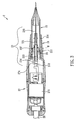
- the eyebrow embroidery machine 2 comprises a connecting sleeve 21, an eyebrow embroidery needle module 23, a watertight O-ring 24, an eyebrow embroidery bushing 25 and a transmission mechanism 27, wherein the connecting sleeve 21 contains a penetrating containing space, an internal screw thread 210 formed on an internal side of an end of the connecting sleeve 21, and a protruding rib 211 formed at a position proximate to the internal screw thread 210.
- At least one circular flange 251 is formed at an external periphery of an end of the eyebrow embroidery bushing 25, wherein the circular flange 251 is integrally formed with the eyebrow embroidery bushing 25 or a standalone circular flange 251 is sheathed or attached onto the eyebrow embroidery bushing 25 individually.
- the circular flange 251 When an end of the eyebrow embroidery bushing 25 is embedded or inserted into another end of the connecting sleeve 21, the circular flange 251 will be pressed and abutted against the connecting sleeve 21 watertightly, such that a relatively large frictional force is produced between the circular flange 251 and an internal wall surface of the connecting sleeve 21, and the eyebrow embroidery bushing 25 will not be separated from the connecting sleeve 21 easily by vibrations.
- the eyebrow embroidery needle module 23 further includes a needle bushing 231 having a substantially H-shaped axial cross-section for partitioning the needle bushing 231 into two independent containing spaces, and an anti-backflow plastic cover 237 sheathed onto the external periphery of the needle bushing 231, wherein the anti-backflow plastic cover 237 is made of an elastic material and has an end fixed onto the needle bushing 231 and another end extended towards the internal screw thread 210, such that a flange 2371 at another end is attached closely with the protruding rib 211 and proximate to a side of the internal screw thread 210 to install the eyebrow embroidery needle module 23 in the connecting sleeve 21, and the dye flowing back into the connecting sleeve 21 is blocked by the anti-backflow plastic cover 237 to prevent any backflow of the dye into the internal screw thread 210.
- the needle bushing 231 includes a core link rod 233 installed in a containing space proximate to an end of the internal screw thread 210, and an eyebrow embroidery needle 235 installed at a containing space proximate to another end of the internal screw thread 210, and a needle head of the eyebrow embroidery needle 235 is passed through the eyebrow embroidery bushing 25 and exposed from another end of the eyebrow embroidery bushing 25, such that an operator can attach a liquid dye onto the needle head.
- the structure of the needle bushing 231 in accordance with the present disclosure can block a portion of the dye at the another end of the needle bushing 231 effectively.
- the watertight O-ring 24 is screwed and engaged with an end of the connecting sleeve 21 through the internal screw thread 210 and attached closed to abut a flange 2371 at another end of the anti-backflow plastic cover 237, such that the flange 2371 at the another end of the anti-backflow plastic cover 237 can be installed between the watertight O-ring 2 and the protruding rib 211 watertightly, such that the dye will not leak from the another end of the anti-backflow plastic cover 237 easily or flow back to the internal screw thread 210.
- the dye or blood entering into the connecting sleeve 21 can be blocked at the another end of the connecting sleeve 21 effectively, so that the dye entering into the eyebrow embroidery bushing 25 and flowing back to an end of the eyebrow embroidery bushing 25 is blocked by the watertight O-ring 24 and accumulated at a position (as indicated by the dotted circle B in FIG. 3 ) proximate to the protruding rib 211.
- a power cord 28 is connected to an end of the transmission mechanism 27 for supplying electric power through the power cord 28, and a motor 271 installed in the transmission mechanism 27 includes a transmission rod 273 extended into another end of the transmission mechanism 27.
- the motor 271 is turned on, the transmission rod 273 is driven to move the transmission rod 273 reciprocally back and forth along the central axis of the eyebrow embroidery machine 2.
- an external screw thread 270 formed at the another end of the transmission mechanism 27 can be screwed with the internal screw thread 210 of the connecting sleeve 21, such that the watertight O-ring 24 and the flange 2371 at the another end of the anti-backflow plastic cover 237 are forcedly pressed between the protruding rib 211 and an end of the transmission mechanism 27 to define a watertight status, and an end of the transmission rod 273 is connected to an end of the core link rod 233.
- the transmission rod 273 is driven by the motor 271
- the core link rod 233, the needle bushing 231, the anti-backflow plastic cover 237 and the eyebrow embroidery needle 235 can be moved reciprocally along the central axis of the eyebrow embroidery machine 2.
- a first magnet 274 is installed at an end of the transmission rod 273 and a second magnet 234 is installed at an end of the core link rod 233, such that the first magnet 274 and the second magnet 234 can be attracted with each other to improve the efficiency of installing the transmission mechanism 27 with the needle mechanism.
- the first magnet 274 and the second magnet 234 will attract each other automatically, so that the transmission rod 273 can be connected to the core link rod 233, and the operator no longer needs to align the transmission rod 273 with the core link rod 233 precisely anymore, and the operator can complete the installation quickly and securely to reduce the installation time and improve the convenience of the installation effectively.
- the other component is a metal piece (such as an iron nugget), instead of installing both magnets between the transmission rod and the core link rod.
- the dye or blood adhered onto the eyebrow embroidery needle 235 can be blocked and prevented from flowing back into the needle bushing 231 or the eyebrow embroidery bushing 25 due to the capillary action, and the dye or blood cannot flow back to an end of the connecting sleeve 21. In other words, the dye or blood will not touch the motor 271 to cause a possible short circuit.
- the dye or blood flowing back into the eyebrow embroidery bushing 25 can be blocked by the circular flange 251 and cannot leak from the external periphery of an end of the eyebrow embroidery bushing or contaminate the operator's hand 25 to affect the product image of the eyebrow embroidery machine.
Landscapes
- Health & Medical Sciences (AREA)
- Engineering & Computer Science (AREA)
- Biomedical Technology (AREA)
- Dermatology (AREA)
- Medical Informatics (AREA)
- Anesthesiology (AREA)
- Virology (AREA)
- Heart & Thoracic Surgery (AREA)
- Hematology (AREA)
- Life Sciences & Earth Sciences (AREA)
- Animal Behavior & Ethology (AREA)
- General Health & Medical Sciences (AREA)
- Public Health (AREA)
- Veterinary Medicine (AREA)
- Sewing Machines And Sewing (AREA)
Priority Applications (2)
| Application Number | Priority Date | Filing Date | Title |
|---|---|---|---|
| PL09011344T PL2292295T3 (pl) | 2009-09-03 | 2009-09-03 | Urządzenie do haftowania brwi |
| EP09011344A EP2292295B1 (en) | 2009-09-03 | 2009-09-03 | Eyebrow embroidery machine |
Applications Claiming Priority (1)
| Application Number | Priority Date | Filing Date | Title |
|---|---|---|---|
| EP09011344A EP2292295B1 (en) | 2009-09-03 | 2009-09-03 | Eyebrow embroidery machine |
Publications (2)
| Publication Number | Publication Date |
|---|---|
| EP2292295A1 EP2292295A1 (en) | 2011-03-09 |
| EP2292295B1 true EP2292295B1 (en) | 2012-06-06 |
Family
ID=41571445
Family Applications (1)
| Application Number | Title | Priority Date | Filing Date |
|---|---|---|---|
| EP09011344A Not-in-force EP2292295B1 (en) | 2009-09-03 | 2009-09-03 | Eyebrow embroidery machine |
Country Status (2)
| Country | Link |
|---|---|
| EP (1) | EP2292295B1 (pl) |
| PL (1) | PL2292295T3 (pl) |
Families Citing this family (3)
| Publication number | Priority date | Publication date | Assignee | Title |
|---|---|---|---|---|
| ES2541334B1 (es) * | 2013-12-17 | 2016-04-25 | Richard BONATTI ANDRADA | Varilla porta-agujas para una máquina de tatuar |
| CN106178246A (zh) * | 2016-09-28 | 2016-12-07 | 周李肖 | 一种纹绣眉成型装置 |
| CN108396472B (zh) * | 2018-05-20 | 2023-06-30 | 贵州省施秉县舞水云台旅游商品开发有限公司 | 一种带有清洗装置的刺绣机 |
Family Cites Families (5)
| Publication number | Priority date | Publication date | Assignee | Title |
|---|---|---|---|---|
| US5471102A (en) * | 1994-05-09 | 1995-11-28 | Becker; Gregory R. | Reciprocating shaft device |
| DE29919199U1 (de) * | 1999-10-22 | 2000-01-20 | MediUm-TECH GmbH, 12681 Berlin | Tattoo- und/oder Permanent-Make-up-Farben-Handgerät |
| US20070060937A1 (en) * | 2005-08-30 | 2007-03-15 | Liu Chen H | Safety needle holder |
| KR100789398B1 (ko) * | 2006-08-11 | 2007-12-28 | 봄텍전자 주식회사 | 문신장치 |
| US7380480B1 (en) * | 2007-02-23 | 2008-06-03 | Cheng-Kun Chen | Safety needle device for tattooing body and eyebrows |
-
2009
- 2009-09-03 EP EP09011344A patent/EP2292295B1/en not_active Not-in-force
- 2009-09-03 PL PL09011344T patent/PL2292295T3/pl unknown
Also Published As
| Publication number | Publication date |
|---|---|
| PL2292295T3 (pl) | 2012-11-30 |
| EP2292295A1 (en) | 2011-03-09 |
Similar Documents
| Publication | Publication Date | Title |
|---|---|---|
| US8181554B2 (en) | Eyebrow embroidery machine | |
| US20170072177A1 (en) | Non-resilient Tattooing Needle and Tattooing Device | |
| US20240167477A1 (en) | Fluid pump assembly | |
| CN105702166B (zh) | 卷轴装置及应用该卷轴装置的电子装置 | |
| ATE546178T1 (de) | Spritzenanordnung und diese enthaltende infusionspumpenanordnung | |
| EP2292295A1 (en) | Eyebrow embroidery machine | |
| WO2006042266A3 (en) | Non-magnetic medical infusion device | |
| US11432918B2 (en) | Oral cavity washing device | |
| RU2012149273A (ru) | Мобильное устройство для введения интраоклурной линзы | |
| WO2014201753A1 (zh) | 牛奶发泡机 | |
| KR102864254B1 (ko) | 살균 모듈 및 이를 구비한 정수기 | |
| KR20230019910A (ko) | 낚시용 릴 | |
| JP2017510420A5 (ja) | ニードルのニードル先端部の取り付け並びに取り外し装置 | |
| CN105343967A (zh) | 注射泵的推拉盒组件和注射泵 | |
| CN211158103U (zh) | 一种美容仪 | |
| JP2019105350A (ja) | バルブ装置 | |
| JP6942336B2 (ja) | 排水栓装置及び栓蓋電動ユニット | |
| KR200460164Y1 (ko) | 눈썹 자수 기계 | |
| CN212346302U (zh) | 一种机头可升降的厨师机 | |
| CN209750854U (zh) | 一种夹持器 | |
| JP2019090337A (ja) | 蠕動ポンプ装置 | |
| CN104878810B (zh) | 一种起泡器快速拆装装置和水龙头 | |
| WO2010064215A3 (en) | A universal tape machine (utm) head assembly for a carton sealing machine | |
| CN207384564U (zh) | 胰岛素自动注射装置 | |
| CN211408776U (zh) | 一种可拆卸沥水架 |
Legal Events
| Date | Code | Title | Description |
|---|---|---|---|
| PUAI | Public reference made under article 153(3) epc to a published international application that has entered the european phase |
Free format text: ORIGINAL CODE: 0009012 |
|
| AK | Designated contracting states |
Kind code of ref document: A1 Designated state(s): AT BE BG CH CY CZ DE DK EE ES FI FR GB GR HR HU IE IS IT LI LT LU LV MC MK MT NL NO PL PT RO SE SI SK SM TR |
|
| AX | Request for extension of the european patent |
Extension state: AL BA RS |
|
| 17P | Request for examination filed |
Effective date: 20110719 |
|
| GRAP | Despatch of communication of intention to grant a patent |
Free format text: ORIGINAL CODE: EPIDOSNIGR1 |
|
| GRAC | Information related to communication of intention to grant a patent modified |
Free format text: ORIGINAL CODE: EPIDOSCIGR1 |
|
| GRAS | Grant fee paid |
Free format text: ORIGINAL CODE: EPIDOSNIGR3 |
|
| GRAA | (expected) grant |
Free format text: ORIGINAL CODE: 0009210 |
|
| AK | Designated contracting states |
Kind code of ref document: B1 Designated state(s): AT BE BG CH CY CZ DE DK EE ES FI FR GB GR HR HU IE IS IT LI LT LU LV MC MK MT NL NO PL PT RO SE SI SK SM TR |
|
| REG | Reference to a national code |
Ref country code: GB Ref legal event code: FG4D |
|
| REG | Reference to a national code |
Ref country code: AT Ref legal event code: REF Ref document number: 560703 Country of ref document: AT Kind code of ref document: T Effective date: 20120615 Ref country code: CH Ref legal event code: EP |
|
| REG | Reference to a national code |
Ref country code: IE Ref legal event code: FG4D |
|
| REG | Reference to a national code |
Ref country code: DE Ref legal event code: R096 Ref document number: 602009007414 Country of ref document: DE Effective date: 20120802 |
|
| REG | Reference to a national code |
Ref country code: NL Ref legal event code: VDEP Effective date: 20120606 |
|
| PG25 | Lapsed in a contracting state [announced via postgrant information from national office to epo] |
Ref country code: NO Free format text: LAPSE BECAUSE OF FAILURE TO SUBMIT A TRANSLATION OF THE DESCRIPTION OR TO PAY THE FEE WITHIN THE PRESCRIBED TIME-LIMIT Effective date: 20120906 Ref country code: SE Free format text: LAPSE BECAUSE OF FAILURE TO SUBMIT A TRANSLATION OF THE DESCRIPTION OR TO PAY THE FEE WITHIN THE PRESCRIBED TIME-LIMIT Effective date: 20120606 Ref country code: FI Free format text: LAPSE BECAUSE OF FAILURE TO SUBMIT A TRANSLATION OF THE DESCRIPTION OR TO PAY THE FEE WITHIN THE PRESCRIBED TIME-LIMIT Effective date: 20120606 Ref country code: CY Free format text: LAPSE BECAUSE OF FAILURE TO SUBMIT A TRANSLATION OF THE DESCRIPTION OR TO PAY THE FEE WITHIN THE PRESCRIBED TIME-LIMIT Effective date: 20120606 Ref country code: LT Free format text: LAPSE BECAUSE OF FAILURE TO SUBMIT A TRANSLATION OF THE DESCRIPTION OR TO PAY THE FEE WITHIN THE PRESCRIBED TIME-LIMIT Effective date: 20120606 |
|
| REG | Reference to a national code |
Ref country code: AT Ref legal event code: MK05 Ref document number: 560703 Country of ref document: AT Kind code of ref document: T Effective date: 20120606 |
|
| REG | Reference to a national code |
Ref country code: LT Ref legal event code: MG4D Effective date: 20120606 |
|
| PG25 | Lapsed in a contracting state [announced via postgrant information from national office to epo] |
Ref country code: LV Free format text: LAPSE BECAUSE OF FAILURE TO SUBMIT A TRANSLATION OF THE DESCRIPTION OR TO PAY THE FEE WITHIN THE PRESCRIBED TIME-LIMIT Effective date: 20120606 Ref country code: HR Free format text: LAPSE BECAUSE OF FAILURE TO SUBMIT A TRANSLATION OF THE DESCRIPTION OR TO PAY THE FEE WITHIN THE PRESCRIBED TIME-LIMIT Effective date: 20120606 Ref country code: SI Free format text: LAPSE BECAUSE OF FAILURE TO SUBMIT A TRANSLATION OF THE DESCRIPTION OR TO PAY THE FEE WITHIN THE PRESCRIBED TIME-LIMIT Effective date: 20120606 Ref country code: GR Free format text: LAPSE BECAUSE OF FAILURE TO SUBMIT A TRANSLATION OF THE DESCRIPTION OR TO PAY THE FEE WITHIN THE PRESCRIBED TIME-LIMIT Effective date: 20120907 |
|
| REG | Reference to a national code |
Ref country code: PL Ref legal event code: T3 |
|
| PG25 | Lapsed in a contracting state [announced via postgrant information from national office to epo] |
Ref country code: RO Free format text: LAPSE BECAUSE OF FAILURE TO SUBMIT A TRANSLATION OF THE DESCRIPTION OR TO PAY THE FEE WITHIN THE PRESCRIBED TIME-LIMIT Effective date: 20120606 Ref country code: BE Free format text: LAPSE BECAUSE OF FAILURE TO SUBMIT A TRANSLATION OF THE DESCRIPTION OR TO PAY THE FEE WITHIN THE PRESCRIBED TIME-LIMIT Effective date: 20120606 Ref country code: AT Free format text: LAPSE BECAUSE OF FAILURE TO SUBMIT A TRANSLATION OF THE DESCRIPTION OR TO PAY THE FEE WITHIN THE PRESCRIBED TIME-LIMIT Effective date: 20120606 Ref country code: IS Free format text: LAPSE BECAUSE OF FAILURE TO SUBMIT A TRANSLATION OF THE DESCRIPTION OR TO PAY THE FEE WITHIN THE PRESCRIBED TIME-LIMIT Effective date: 20121006 Ref country code: NL Free format text: LAPSE BECAUSE OF FAILURE TO SUBMIT A TRANSLATION OF THE DESCRIPTION OR TO PAY THE FEE WITHIN THE PRESCRIBED TIME-LIMIT Effective date: 20120606 Ref country code: CZ Free format text: LAPSE BECAUSE OF FAILURE TO SUBMIT A TRANSLATION OF THE DESCRIPTION OR TO PAY THE FEE WITHIN THE PRESCRIBED TIME-LIMIT Effective date: 20120606 Ref country code: EE Free format text: LAPSE BECAUSE OF FAILURE TO SUBMIT A TRANSLATION OF THE DESCRIPTION OR TO PAY THE FEE WITHIN THE PRESCRIBED TIME-LIMIT Effective date: 20120606 Ref country code: SK Free format text: LAPSE BECAUSE OF FAILURE TO SUBMIT A TRANSLATION OF THE DESCRIPTION OR TO PAY THE FEE WITHIN THE PRESCRIBED TIME-LIMIT Effective date: 20120606 |
|
| PG25 | Lapsed in a contracting state [announced via postgrant information from national office to epo] |
Ref country code: PT Free format text: LAPSE BECAUSE OF FAILURE TO SUBMIT A TRANSLATION OF THE DESCRIPTION OR TO PAY THE FEE WITHIN THE PRESCRIBED TIME-LIMIT Effective date: 20121008 |
|
| PLBE | No opposition filed within time limit |
Free format text: ORIGINAL CODE: 0009261 |
|
| STAA | Information on the status of an ep patent application or granted ep patent |
Free format text: STATUS: NO OPPOSITION FILED WITHIN TIME LIMIT |
|
| PG25 | Lapsed in a contracting state [announced via postgrant information from national office to epo] |
Ref country code: MC Free format text: LAPSE BECAUSE OF NON-PAYMENT OF DUE FEES Effective date: 20120930 Ref country code: DK Free format text: LAPSE BECAUSE OF FAILURE TO SUBMIT A TRANSLATION OF THE DESCRIPTION OR TO PAY THE FEE WITHIN THE PRESCRIBED TIME-LIMIT Effective date: 20120606 Ref country code: ES Free format text: LAPSE BECAUSE OF FAILURE TO SUBMIT A TRANSLATION OF THE DESCRIPTION OR TO PAY THE FEE WITHIN THE PRESCRIBED TIME-LIMIT Effective date: 20120917 |
|
| 26N | No opposition filed |
Effective date: 20130307 |
|
| REG | Reference to a national code |
Ref country code: IE Ref legal event code: MM4A |
|
| REG | Reference to a national code |
Ref country code: DE Ref legal event code: R097 Ref document number: 602009007414 Country of ref document: DE Effective date: 20130307 |
|
| PG25 | Lapsed in a contracting state [announced via postgrant information from national office to epo] |
Ref country code: BG Free format text: LAPSE BECAUSE OF FAILURE TO SUBMIT A TRANSLATION OF THE DESCRIPTION OR TO PAY THE FEE WITHIN THE PRESCRIBED TIME-LIMIT Effective date: 20120906 Ref country code: IE Free format text: LAPSE BECAUSE OF NON-PAYMENT OF DUE FEES Effective date: 20120903 |
|
| PG25 | Lapsed in a contracting state [announced via postgrant information from national office to epo] |
Ref country code: MT Free format text: LAPSE BECAUSE OF FAILURE TO SUBMIT A TRANSLATION OF THE DESCRIPTION OR TO PAY THE FEE WITHIN THE PRESCRIBED TIME-LIMIT Effective date: 20120606 |
|
| PGFP | Annual fee paid to national office [announced via postgrant information from national office to epo] |
Ref country code: GB Payment date: 20130828 Year of fee payment: 5 Ref country code: FR Payment date: 20130911 Year of fee payment: 5 |
|
| PG25 | Lapsed in a contracting state [announced via postgrant information from national office to epo] |
Ref country code: TR Free format text: LAPSE BECAUSE OF FAILURE TO SUBMIT A TRANSLATION OF THE DESCRIPTION OR TO PAY THE FEE WITHIN THE PRESCRIBED TIME-LIMIT Effective date: 20120606 |
|
| REG | Reference to a national code |
Ref country code: CH Ref legal event code: PL |
|
| PG25 | Lapsed in a contracting state [announced via postgrant information from national office to epo] |
Ref country code: SM Free format text: LAPSE BECAUSE OF FAILURE TO SUBMIT A TRANSLATION OF THE DESCRIPTION OR TO PAY THE FEE WITHIN THE PRESCRIBED TIME-LIMIT Effective date: 20120606 Ref country code: LU Free format text: LAPSE BECAUSE OF NON-PAYMENT OF DUE FEES Effective date: 20120903 |
|
| PG25 | Lapsed in a contracting state [announced via postgrant information from national office to epo] |
Ref country code: LI Free format text: LAPSE BECAUSE OF NON-PAYMENT OF DUE FEES Effective date: 20130930 Ref country code: CH Free format text: LAPSE BECAUSE OF NON-PAYMENT OF DUE FEES Effective date: 20130930 Ref country code: HU Free format text: LAPSE BECAUSE OF FAILURE TO SUBMIT A TRANSLATION OF THE DESCRIPTION OR TO PAY THE FEE WITHIN THE PRESCRIBED TIME-LIMIT Effective date: 20090903 |
|
| GBPC | Gb: european patent ceased through non-payment of renewal fee |
Effective date: 20140903 |
|
| REG | Reference to a national code |
Ref country code: FR Ref legal event code: ST Effective date: 20150529 |
|
| PG25 | Lapsed in a contracting state [announced via postgrant information from national office to epo] |
Ref country code: MK Free format text: LAPSE BECAUSE OF FAILURE TO SUBMIT A TRANSLATION OF THE DESCRIPTION OR TO PAY THE FEE WITHIN THE PRESCRIBED TIME-LIMIT Effective date: 20120606 Ref country code: GB Free format text: LAPSE BECAUSE OF NON-PAYMENT OF DUE FEES Effective date: 20140903 |
|
| PG25 | Lapsed in a contracting state [announced via postgrant information from national office to epo] |
Ref country code: FR Free format text: LAPSE BECAUSE OF NON-PAYMENT OF DUE FEES Effective date: 20140930 |
|
| PGFP | Annual fee paid to national office [announced via postgrant information from national office to epo] |
Ref country code: IT Payment date: 20160919 Year of fee payment: 8 |
|
| PGFP | Annual fee paid to national office [announced via postgrant information from national office to epo] |
Ref country code: PL Payment date: 20160729 Year of fee payment: 8 |
|
| PGFP | Annual fee paid to national office [announced via postgrant information from national office to epo] |
Ref country code: DE Payment date: 20161129 Year of fee payment: 8 |
|
| REG | Reference to a national code |
Ref country code: DE Ref legal event code: R119 Ref document number: 602009007414 Country of ref document: DE |
|
| PG25 | Lapsed in a contracting state [announced via postgrant information from national office to epo] |
Ref country code: DE Free format text: LAPSE BECAUSE OF NON-PAYMENT OF DUE FEES Effective date: 20180404 |
|
| PG25 | Lapsed in a contracting state [announced via postgrant information from national office to epo] |
Ref country code: IT Free format text: LAPSE BECAUSE OF NON-PAYMENT OF DUE FEES Effective date: 20170903 |
|
| PG25 | Lapsed in a contracting state [announced via postgrant information from national office to epo] |
Ref country code: PL Free format text: LAPSE BECAUSE OF NON-PAYMENT OF DUE FEES Effective date: 20170903 |