EP2292037B1 - Inter-cell interference avoidance for downlink transmission - Google Patents
Inter-cell interference avoidance for downlink transmission Download PDFInfo
- Publication number
- EP2292037B1 EP2292037B1 EP09770377.1A EP09770377A EP2292037B1 EP 2292037 B1 EP2292037 B1 EP 2292037B1 EP 09770377 A EP09770377 A EP 09770377A EP 2292037 B1 EP2292037 B1 EP 2292037B1
- Authority
- EP
- European Patent Office
- Prior art keywords
- codebook
- threshold
- interfering
- channel
- base station
- Prior art date
- Legal status (The legal status is an assumption and is not a legal conclusion. Google has not performed a legal analysis and makes no representation as to the accuracy of the status listed.)
- Not-in-force
Links
Images


Classifications
-
- H—ELECTRICITY
- H04—ELECTRIC COMMUNICATION TECHNIQUE
- H04B—TRANSMISSION
- H04B7/00—Radio transmission systems, i.e. using radiation field
- H04B7/02—Diversity systems; Multi-antenna system, i.e. transmission or reception using multiple antennas
- H04B7/022—Site diversity; Macro-diversity
- H04B7/024—Co-operative use of antennas of several sites, e.g. in co-ordinated multipoint or co-operative multiple-input multiple-output [MIMO] systems
-
- H—ELECTRICITY
- H04—ELECTRIC COMMUNICATION TECHNIQUE
- H04B—TRANSMISSION
- H04B7/00—Radio transmission systems, i.e. using radiation field
- H04B7/02—Diversity systems; Multi-antenna system, i.e. transmission or reception using multiple antennas
- H04B7/04—Diversity systems; Multi-antenna system, i.e. transmission or reception using multiple antennas using two or more spaced independent antennas
- H04B7/06—Diversity systems; Multi-antenna system, i.e. transmission or reception using multiple antennas using two or more spaced independent antennas at the transmitting station
- H04B7/0613—Diversity systems; Multi-antenna system, i.e. transmission or reception using multiple antennas using two or more spaced independent antennas at the transmitting station using simultaneous transmission
- H04B7/0615—Diversity systems; Multi-antenna system, i.e. transmission or reception using multiple antennas using two or more spaced independent antennas at the transmitting station using simultaneous transmission of weighted versions of same signal
- H04B7/0619—Diversity systems; Multi-antenna system, i.e. transmission or reception using multiple antennas using two or more spaced independent antennas at the transmitting station using simultaneous transmission of weighted versions of same signal using feedback from receiving side
- H04B7/0636—Feedback format
- H04B7/0639—Using selective indices, e.g. of a codebook, e.g. pre-distortion matrix index [PMI] or for beam selection
-
- H—ELECTRICITY
- H04—ELECTRIC COMMUNICATION TECHNIQUE
- H04B—TRANSMISSION
- H04B7/00—Radio transmission systems, i.e. using radiation field
- H04B7/02—Diversity systems; Multi-antenna system, i.e. transmission or reception using multiple antennas
- H04B7/04—Diversity systems; Multi-antenna system, i.e. transmission or reception using multiple antennas using two or more spaced independent antennas
- H04B7/06—Diversity systems; Multi-antenna system, i.e. transmission or reception using multiple antennas using two or more spaced independent antennas at the transmitting station
- H04B7/0613—Diversity systems; Multi-antenna system, i.e. transmission or reception using multiple antennas using two or more spaced independent antennas at the transmitting station using simultaneous transmission
- H04B7/0615—Diversity systems; Multi-antenna system, i.e. transmission or reception using multiple antennas using two or more spaced independent antennas at the transmitting station using simultaneous transmission of weighted versions of same signal
- H04B7/0619—Diversity systems; Multi-antenna system, i.e. transmission or reception using multiple antennas using two or more spaced independent antennas at the transmitting station using simultaneous transmission of weighted versions of same signal using feedback from receiving side
- H04B7/0658—Feedback reduction
-
- H—ELECTRICITY
- H04—ELECTRIC COMMUNICATION TECHNIQUE
- H04L—TRANSMISSION OF DIGITAL INFORMATION, e.g. TELEGRAPHIC COMMUNICATION
- H04L25/00—Baseband systems
- H04L25/02—Details ; arrangements for supplying electrical power along data transmission lines
- H04L25/03—Shaping networks in transmitter or receiver, e.g. adaptive shaping networks
- H04L25/03006—Arrangements for removing intersymbol interference
- H04L25/03821—Inter-carrier interference cancellation [ICI]
-
- H—ELECTRICITY
- H04—ELECTRIC COMMUNICATION TECHNIQUE
- H04L—TRANSMISSION OF DIGITAL INFORMATION, e.g. TELEGRAPHIC COMMUNICATION
- H04L25/00—Baseband systems
- H04L25/02—Details ; arrangements for supplying electrical power along data transmission lines
- H04L25/03—Shaping networks in transmitter or receiver, e.g. adaptive shaping networks
- H04L25/03891—Spatial equalizers
- H04L25/03961—Spatial equalizers design criteria
- H04L25/03968—Spatial equalizers design criteria mean-square error [MSE]
-
- H—ELECTRICITY
- H04—ELECTRIC COMMUNICATION TECHNIQUE
- H04W—WIRELESS COMMUNICATION NETWORKS
- H04W72/00—Local resource management
- H04W72/50—Allocation or scheduling criteria for wireless resources
- H04W72/54—Allocation or scheduling criteria for wireless resources based on quality criteria
- H04W72/541—Allocation or scheduling criteria for wireless resources based on quality criteria using the level of interference
-
- H—ELECTRICITY
- H04—ELECTRIC COMMUNICATION TECHNIQUE
- H04B—TRANSMISSION
- H04B7/00—Radio transmission systems, i.e. using radiation field
- H04B7/02—Diversity systems; Multi-antenna system, i.e. transmission or reception using multiple antennas
- H04B7/04—Diversity systems; Multi-antenna system, i.e. transmission or reception using multiple antennas using two or more spaced independent antennas
- H04B7/0413—MIMO systems
- H04B7/0417—Feedback systems
-
- H—ELECTRICITY
- H04—ELECTRIC COMMUNICATION TECHNIQUE
- H04L—TRANSMISSION OF DIGITAL INFORMATION, e.g. TELEGRAPHIC COMMUNICATION
- H04L1/00—Arrangements for detecting or preventing errors in the information received
- H04L1/0001—Systems modifying transmission characteristics according to link quality, e.g. power backoff
- H04L1/0002—Systems modifying transmission characteristics according to link quality, e.g. power backoff by adapting the transmission rate
-
- H—ELECTRICITY
- H04—ELECTRIC COMMUNICATION TECHNIQUE
- H04L—TRANSMISSION OF DIGITAL INFORMATION, e.g. TELEGRAPHIC COMMUNICATION
- H04L1/00—Arrangements for detecting or preventing errors in the information received
- H04L1/004—Arrangements for detecting or preventing errors in the information received by using forward error control
- H04L1/0041—Arrangements at the transmitter end
Definitions
- the present application relates generally to wireless communication networks and, more specifically, to an interference avoidance of edge-cells in a wireless communications network.
- a base station such as base station 101, 102, or 103, may employ directional antennas to support a plurality of sectors within the coverage area.
- base stations 102 and 103 are depicted approximately in the center of coverage areas 120 and 125, respectively.
- the use of directional antennas may locate the base station near the edge of the coverage area, for example, at the point of a cone-shaped or pear-shaped coverage area.
- the connection to network 130 from base station 101 may comprise a broadband connection, for example, a fiber optic line, to servers located in a central office or another operating company point-of-presence.
- the servers may provide communication to an Internet gateway for internet protocol-based communications and to a public switched telephone network gateway for voice-based communications.
- voice-based communications in the form of voice-over-IP (VoIP)
- VoIP voice-over-IP
- the traffic may be forwarded directly to the Internet gateway instead of the PSTN gateway.
- the servers, Internet gateway, and public switched telephone network gateway are not shown in FIGURE 1A .
- the connection to network 130 may be provided by different network nodes and equipment.
- Transmitter 205 comprises a multi-codeword MIMO encoder 220 and a plurality of antennas 225, each of which is operable to transmit a different data stream 230 generated by encoder 220.
- Receiver 210 comprises a spatial processing block 250 and a plurality of antennas 255, each of which is operable to receive a combined data stream 260 from a plurality of sources including antennas 225 of transmitter 205.
- Spatial processing block 250 is operable to decode the combined data stream 260 into data streams 265, which are substantially identical to the data streams 230 transmitted by antennas 225.
- Demultiplexer 305 is operable to demultiplex the information block into a plurality of smaller information blocks, or streams 340.
- Each CRC block 310 is operable to add CRC data to the associated stream 340.
- each coder 315 is operable to code the stream 340 and each modulator 320 is operable to modulate the coded stream 340.
- the resulting streams are processed through a precoding algorithm 325 and transmitted from separate antennas 225.
- Precoding 325 is used for multi-layer beamforming in order to maximize the throughput performance of a multiple receive antenna system.
- the multiple streams of the signals are emitted from the transmit antennas with independent and appropriate weighting per each antenna such that the link through-put is maximized at the receiver output.
- Precoding algorithms for multi-codeword MIMO can be sub-divided into linear and nonlinear precoding types.
- Linear precoding approaches can achieve reasonable throughput performance with lower complexity relateved to nonlinear precoding approaches.
- Linear precoding includes unitary precoding and zero-forcing (hereinafter "ZF") precoding.
- Nonlinear precoding can achieve near optimal capacity at the expense of complexity.
- Nonlinear precoding is designed based on the concept of Dirty paper coding (hereinafter "DPC") which shows that any known interference at the transmitter can be subtracted without the penalty of radio resources if the optimal precoding scheme can be applied on the transmit signal.
- DPC Dirty paper coding
- FIGURE 4 illustrates wireless subscriber station 116 according to embodiments of the present disclosure.
- the embodiment of wireless subscriber station 116 illustrated in FIGURE 4 is for illustration only. Other embodiments of the wireless subscriber station 116 could be used without departing from the scope of this disclosure.
- Main processor 440 also is operable to estimate the channel matrix from the serving base station (e.g., BS 102). Main processor 440 further is operable to estimate channel matrices from the strong interfering base stations (e.g., BS 103) when the subscriber station (e.g., SS 116) is in an edge-cell (e.g., the edge of two or more coverage areas 120, 125).
- the serving base station e.g., BS 102
- Main processor 440 further is operable to estimate channel matrices from the strong interfering base stations (e.g., BS 103) when the subscriber station (e.g., SS 116) is in an edge-cell (e.g., the edge of two or more coverage areas 120, 125).
- N T is the number of transmit antennas at BS 102 and BS 103
- N R is the number of receive antennas at the user equipments.
- H 11 , H 12 , H 21 , and H 22 are the respective channel gains; where Y i is the N R ⁇ 1 vector of received signal at subscriber station i; X i is the N T ⁇ 1 vector of transmitted signal at base station i; and N i is the N R ⁇ 1 AWGN noise vector.
- SS 116 is denoted as "1" such that Y 1 is the the N R ⁇ 1 vector of received signal at SS 116.
- each subscriber stations indirectly feeds back the codebook vector that will cause the highest interference to the subscriber stations own signal.
- the codebook vector is fed-back to the interfering base station.
- the interfering base station excludes the reported codebook vector from the codebook and performs codebook vector selection on a restricted. In this way, the cell-edge throughput can be improved.
- the user equipment will only report the codebook vector which causes the strongest interference and even with restrict codebook, the interference caused by the interfering base station (interfering eNB) may still be very high if not the highest.
- FIGURES 5A and 5B illustrate a codebook partitioner 470 according to embodiments of the present disclosure.
- the embodiments of the codebook partitioner 470 shown in FIGURES 5A and 5B are for illustration only. Other embodiments of the codebook partitioner 470 can be used without departing from the scope of this disclosure.
- interfering base stations can avoid interference with each other by choosing different codebook vectors within a standardized codebook.
- BS 102 and BS 103 share information related to all the channel matrices.
- BS 102 and BS 103 iteratively find good precoding vectors and matrices that avoid interference in the others respective signals.
- BS 102 receives and process the channel feedback information received from SS 116 in step 820.
- BS 102 processes the channel feedback information and identifies that the interfering base station is BS 103. Then BS 102 forwards the channel feedback information related to all the channel matrices obtained from SS 116 to BS 103 in step 825.
- step 905 an algorithm is initialized.
- BS 102 computes a possible precoding vector or matrix for BS 103 (let P 2 be the precoding vector or matrix). Also, BS 102 searches the precoding vector or matrix to maximize (or minimize) some performance measures based on the assumption that BS 103 is using P 2 (let P 1 be the resulting precoding vector or matrix) . For example, BS 102 can search the precoding vector or matrix which maximizes the SNR or throughput.
- BS 103 may choose to follow a recommendation based on the SINR improvement reports from various base stations.
- a rank of the requests can be ordered based on ⁇ CQI and the channel between BS 103 and SS 115.
- serving base stations configure the target tolerable interference level threshold ⁇ 462 and a target channel (e.g., SINR) improvement ⁇ CQI for participating subscriber stations.
- BS 102 sends the configuration message and activation message as unified message to SS 116.
- SS 116 performs feedback information generation (discussed hereinabove with respect to FIGURE 10 , step 1015).
- SS 116 configures the IAM threshold ⁇ locally to be sent to BS 103.
- SS 116 reports the feedback information only if the channel (e.g., SINR) improvement ⁇ CQI is greater than the target channel improvement ⁇ CQI.
- SS 116 calculates that the channel improvement ⁇ CQI is not greater than the target channel improvement ⁇ CQI, then SS 116 does not send the feedback information to BS 102 or BS 103. In some such embodiments, if SS 116 calculates that the channel improvement ⁇ CQI is not greater than the target channel improvement ⁇ CQI, then SS 116 sends a message to BS 102 indicating that SS 116 cannot meet the target channel improvement ⁇ CQI. Accordingly, based on the feedback information related to the average SINR for SS 116, BS 102 may decide to choose different strategies to serve SS 116.
Description
- The present application relates generally to wireless communication networks and, more specifically, to an interference avoidance of edge-cells in a wireless communications network.
- In a wireless communications network, multiple base stations (also referred to as "eNBs") use a standardized codebook for precoding transmission to their respective user equipments (UEs), using multiple transmit antennas. A typical problem of this procedure occurs where several base stations are serving their intended UEs while interfering with each other's signal. This scenario is called "inter-cell interference." Inter-cell interference constrains the throughput of the wireless network.
-
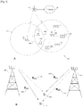
FIGURE 1B illustrates an exemplarywireless network 100. In such example, base station (BS) 102 is the serving base station for subscriber station (SS) 116, e.g., communications to and from SS 116 are conducted throughBS 102. BS 103 is the serving base station for SS 115, e.g., communications to and from SS 115 are conducted through BS 103. SS 116 is located in proximity to SS 115. Further, BS 102 is communicating withSS 116 using the same frequency band that BS 103 is using to communicate withSS 115. Therefore, SS 116 receivescommunications 140 fromBS 102. However, SS 116 also receives communications 145 (e.g., interfering communications) from BS 103. Further, SS 115 receivescommunications 150 fromBS 103. Additionally, SS 115 also receives communications 155 (e.g., interfering communications) from BS 102. Since SS 116 and SS 115 are in close proximity and using the same frequency band simultaneously, the communications between the subscriber stations, SS 116 and SS 115, and their respective base stations, BS 102 and BS 103, interfere with each other. -
Document EP 1 912 347 A1 discloses a method, base station and user equipment for transmitting data in a mobile communications system, wherein said data is transmitted on at least one channel between at least one base station with multiple antennas and at least one user equipment. The base station applies preceding to the data based on a set of predefined codebooks. A first tracking mode with a first codebook from said set of predefined codebooks is used for said precoding, and at least a second tracking mode with at least a second codebook from said set of predefined codebooks is used for said precoding. The base station switches between said first tracking mode and said second tracking mode depending on at least one condition of said channel. - A subscriber station capable of performing interference avoidance is provided. The subscriber station includes a plurality of receive antennas and a processor configured to perform channel estimation. The processor identifies a first signal from a serving base station and a second signal from an interfering base station. The processor also generates and transmits compressed feedback information. The compressed feedback information includes a threshold information and codebook vector information for the interfering base station. The compressed feedback information is used by the serving base station or the interfering base station to select codebook vector information in order to avoid interference in communications between the serving base station and the subscriber station.
- A wireless communications network is provided. The network includes a plurality of base stations and a plurality of subscriber stations. At least two of said base stations are capable of performing interference avoidance. At least one base station including a receiver capable of receiving compressed feedback information from at least one subscriber station. The compressed feedback information comprising at least one of a recommended set of codebook information and a restricted set of codebook information. The base station also includes a controller configured to use the compressed feedback information to select codebook vector information in order to avoid interference in communications between the serving base station and the subscriber station.
- A method of interference avoidance is provided. The method includes transmitting compressed feedback information. The compressed feedback information includes an interference avoidance message indicating at least one of a preferred set of codebook information and a restricted set of codebook information. The compressed feedback information is used to select, at least in part, a codebook.
- Before undertaking the DETAILED DESCRIPTION OF THE INVENTION below, it may be advantageous to set forth definitions of certain words and phrases used throughout this patent document: the terms "include" and "comprise," as well as derivatives thereof, mean inclusion without limitation; the term "or," is inclusive, meaning and/or; the phrases "associated with" and "associated therewith," as well as derivatives thereof, may mean to include, be included within, interconnect with, contain, be contained within, connect to or with, couple to or with, be communicable with, cooperate with, interleave, juxtapose, be proximate to, be bound to or with, have, have a property of, or the like; and the term "controller" means any device, system or part thereof that controls at least one operation, such a device may be implemented in hardware, firmware or software, or some combination of at least two of the same. It should be noted that the functionality associated with any particular controller may be centralized or distributed, whether locally or remotely. Definitions for certain words and phrases are provided throughout this patent document, those of ordinary skill in the art should understand that in many, if not most instances, such definitions apply to prior, as well as future uses of such defined words and phrases.
- For a more complete understanding of the present disclosure and its advantages, reference is now made to the following description taken in conjunction with the accompanying drawings, in which like reference numerals represent like parts:
-
FIGURE 1A illustrates exemplarywireless network 100 that is capable of decoding data streams according to an exemplary embodiment of the disclosure; -
FIGURE 1B illustrates exemplarywireless network 100 according to embodiments of the present disclosure; -
FIGURE 2 illustrates aMIMO system 200 that is capable of decoding data streams according to an embodiment of the present disclosure; -
FIGURE 3 illustrates details of multi-codeword MIMO encoder according to an embodiment of the present disclosure; -
FIGURE 4 illustrates wireless subscriber station according to embodiments of the present disclosure; -
FIGURES 5A and 5B illustrate acodebook partitioner 470 according to embodiments of the present disclosure; -
FIGURE 6 illustrates a time diagram for interference avoidance according to embodiments of the present disclosure; -
FIGURE 7 illustrates a process for interference avoidance according to embodiments of the present disclosure; -
FIGURE 8 illustrates another process for interference avoidance according to embodiments of the present disclosure; -
FIGURE 9 illustrates a process for codebook selection according to embodiments of the present disclosure; and -
FIGURE 10 illustrates another process for interference avoidance according to embodiments of the present disclosure. -
FIGURES 1 through 10 , discussed below, and the various embodiments used to describe the principles of the present disclosure in this patent document are by way of illustration only and should not be construed in any way to limit the scope of the disclosure. Those skilled in the art will understand that the principles of the present disclosure may be implemented in any suitably arranged wireless communication network. - With regard to the following description, it is noted that the LTE term "node B" is another term for "base station" used below. Further, the term "cell" is a logic concept which can represent a "base station" or a "sector" belongs to a "base station". In this patent, "cell" and "base station" are used interchangeably to indicate the actual transmission units (may be "sector" or "base station" etc.) in the wireless system. Also, the LTE term "user equipment" or "UE" is another term for "subscriber station" used below.
-
FIGURE 1A illustrates exemplarywireless network 100 that is capable of decoding data streams according to one embodiment of the present disclosure. In the illustrated embodiment,wireless network 100 includes base station (BS) 101, base station (BS) 102, and base station (BS) 103.Base station 101 communicates withbase station 102 andbase station 103.Base station 101 also communicates with Internet protocol (IP)network 130, such as the Internet, a proprietary IP network, or other data network. -
Base station 102 provides wireless broadband access tonetwork 130, viabase station 101, to a first plurality of subscriber stations withincoverage area 120 ofbase station 102. The first plurality of subscriber stations includes subscriber station (SS) 111, subscriber station (SS) 112, subscriber station (SS) 113, subscriber station (SS) 114, subscriber station (SS) 115 and subscriber station (SS) 116. Subscriber station (SS) may be any wireless communication device, such as, but not limited to, a mobile phone, mobile PDA and any mobile station (MS). In an exemplary embodiment,SS 111 may be located in a small business (SB),SS 112 may be located in an enterprise (E),SS 113 may be located in a WiFi hotspot (HS),SS 114 may be located in a residence,SS 115 may be a mobile (M) device, andSS 116 may be a mobile (M) device. -
Base station 103 provides wireless broadband access tonetwork 130, viabase station 101, to a second plurality of subscriber stations withincoverage area 125 ofbase station 103. The second plurality of subscriber stations includessubscriber station 115 andsubscriber station 116. In alternate embodiments,base stations base station 101. - In other embodiments,
base station 101 may be in communication with either fewer or more base stations. Furthermore, while only six subscriber stations are shown inFIGURE 1A , it is understood thatwireless network 100 may provide wireless broadband access to more than six subscriber stations. It is noted thatsubscriber station 115 andsubscriber station 116 are on the edge of bothcoverage area 120 andcoverage area 125.Subscriber station 115 andsubscriber station 116 each communicate with bothbase station 102 andbase station 103 and may be said to be cell-edge devices interfering with each other. For example, the communications betweenBS 102 andSS 116 may be interfering with the communications betweenBS 103 andSS 115. Additionally, the communications betweenBS 103 andSS 115 may be interfering with the communications betweenBS 102 andSS 116. - In an exemplary embodiment, base stations 101-103 may communicate with each other and with subscriber stations 111-116 using an IEEE-802.16 wireless metropolitan area network standard, such as, for example, an IEEE-802.16e standard. In another embodiment, however, a different wireless protocol may be employed, such as, for example, a HIPERMAN wireless metropolitan area network standard.
Base station 101 may communicate through direct line-of-sight or non-line-of-sight withbase station 102 andbase station 103, depending on the technology used for the wireless backhaul.Base station 102 andbase station 103 may each communicate through non-line-of-sight with subscriber stations 111-116 using OFDM and/or OFDMA techniques. -
Base station 102 may provide a T1 level service tosubscriber station 112 associated with the enterprise and a fractional T1 level service tosubscriber station 111 associated with the small business.Base station 102 may provide wireless backhaul forsubscriber station 113 associated with the WiFi hotspot, which may be located in an airport, cafe, hotel, or college campus.Base station 102 may provide digital subscriber line (DSL) level service tosubscriber stations - Subscriber stations 111-116 may use the broadband access to
network 130 to access voice, data, video, video teleconferencing, and/or other broadband services. In an exemplary embodiment, one or more of subscriber stations 111-116 may be associated with an access point (AP) of a WiFi WLAN.Subscriber station 116 may be any of a number of mobile devices, including a wireless-enabled laptop computer, personal data assistant, notebook, handheld device, or other wireless-enabled device.Subscriber station 114 may be, for example, a wireless-enabled personal computer, a laptop computer, a gateway, or another device. - Dotted lines show the approximate extents of
coverage areas coverage areas - Also, the coverage areas associated with base stations are not constant over time and may be dynamic (expanding or contracting or changing shape) based on changing transmission power levels of the base station and/or the subscriber stations, weather conditions, and other factors. In an embodiment, the radius of the coverage areas of the base stations, for example,
coverage areas base stations - As is well known in the art, a base station, such as
base station FIGURE 1 ,base stations coverage areas - The connection to network 130 from
base station 101 may comprise a broadband connection, for example, a fiber optic line, to servers located in a central office or another operating company point-of-presence. The servers may provide communication to an Internet gateway for internet protocol-based communications and to a public switched telephone network gateway for voice-based communications. In the case of voice-based communications in the form of voice-over-IP (VoIP), the traffic may be forwarded directly to the Internet gateway instead of the PSTN gateway. The servers, Internet gateway, and public switched telephone network gateway are not shown inFIGURE 1A . In another embodiment, the connection to network 130 may be provided by different network nodes and equipment. - In accordance with an embodiment of the present disclosure, one or more of base stations 101-103 and/or one or more of subscriber stations 111-116 comprises a receiver that is operable to decode a plurality of data streams received as a combined data stream from a plurality of transmit antennas using an MMSE-SIC algorithm. As described in more detail below, the receiver is operable to determine a decoding order for the data streams based on a decoding prediction metric for each data stream that is calculated based on a strength-related characteristic of the data stream. Thus, in general, the receiver is able to decode the strongest data stream first, followed by the next strongest data stream, and so on. As a result, the decoding performance of the receiver is improved as compared to a receiver that decodes streams in a random or pre-determined order without being as complex as a receiver that searches all possible decoding orders to find the optimum order.
-
FIGURE 2 illustrates aMIMO system 200 that is capable of decoding data streams according to an embodiment of the present disclosure.MIMO system 200 comprises atransmitter 205 and areceiver 210 that are operable to communicate over awireless interface 215. -
Transmitter 205 comprises amulti-codeword MIMO encoder 220 and a plurality ofantennas 225, each of which is operable to transmit adifferent data stream 230 generated byencoder 220.Receiver 210 comprises aspatial processing block 250 and a plurality ofantennas 255, each of which is operable to receive a combineddata stream 260 from a plurality ofsources including antennas 225 oftransmitter 205.Spatial processing block 250 is operable to decode the combineddata stream 260 intodata streams 265, which are substantially identical to the data streams 230 transmitted byantennas 225. -
Spatial processing block 250 is operable to decodedata streams 265 from the combineddata stream 260 using an MMSE-SIC procedure that selects an order for decoding thestreams 265 based on a decoding prediction metric (DPM) for eachstream 265. The DPM for eachdata stream 265 is based on a strength-related characteristic associated with thedata stream 265. Thus, for example, the DPM may be based on a capacity of the channel associated with thedata stream 265, an effective signal-to-interference and noise ratio (SINR) for thedata stream 265 and/or any other suitable strength-related characteristic. Using this process for decoding,receiver 210 is able to provide better performance than a receiver that decodes streams in a random order without introducing the complexity of a receiver that searches all possible decoding orders to find an optimum decoding order. -
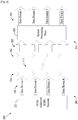
FIGURE 3 illustrates details ofmulti-codeword MIMO encoder 220 according to an embodiment of the present disclosure. For this embodiment,encoder 220 comprises a demultiplexer (demux) 305, a plurality of cyclic redundancy code (CRC) blocks 310, a plurality of coders 315, a plurality of modulators 320, and a pre-coder 325.Encoder 220 is operable to receive an information block and to generatedata streams 230 based on the information block for transmission overantennas 225. Although the illustrated embodiment shows two sets of components 310, 315 and 320 to generate twostreams 230a-b for transmission by twoantennas 225a b, it will be understood thatencoder 220 may comprise any suitable number of component sets 310, 315, 320 and 325 based on any suitable number ofstreams 230 to be generated. -
Demultiplexer 305 is operable to demultiplex the information block into a plurality of smaller information blocks, or streams 340. Each CRC block 310 is operable to add CRC data to the associated stream 340. Following the addition of CRC data, each coder 315 is operable to code the stream 340 and each modulator 320 is operable to modulate the coded stream 340. After coding and modulation, the resulting streams, which are equivalent todata streams 230, are processed through aprecoding algorithm 325 and transmitted fromseparate antennas 225. - Because
encoder 220 is a multi-codeword MIMO encoder, different modulation and coding may be used on each of the individual streams 340. Thus, for example, coder 315a may perform different coding fromcoder 315b andmodulator 320a may perform different modulation frommodulator 320b. Using multi-codeword transmission, a CRC check may optionally be performed on each of the codewords before the codeword is canceled form the overall signal atreceiver 210. When this check is performed, interference propagation may be avoided in the cancellation process by ensuring that only correctly received codewords are canceled. -
Precoding 325 is used for multi-layer beamforming in order to maximize the throughput performance of a multiple receive antenna system. The multiple streams of the signals are emitted from the transmit antennas with independent and appropriate weighting per each antenna such that the link through-put is maximized at the receiver output. Precoding algorithms for multi-codeword MIMO can be sub-divided into linear and nonlinear precoding types. Linear precoding approaches can achieve reasonable throughput performance with lower complexity relateved to nonlinear precoding approaches. Linear precoding includes unitary precoding and zero-forcing (hereinafter "ZF") precoding. Nonlinear precoding can achieve near optimal capacity at the expense of complexity. Nonlinear precoding is designed based on the concept of Dirty paper coding (hereinafter "DPC") which shows that any known interference at the transmitter can be subtracted without the penalty of radio resources if the optimal precoding scheme can be applied on the transmit signal. -
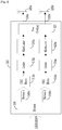
FIGURE 4 illustrateswireless subscriber station 116 according to embodiments of the present disclosure. The embodiment ofwireless subscriber station 116 illustrated inFIGURE 4 is for illustration only. Other embodiments of thewireless subscriber station 116 could be used without departing from the scope of this disclosure. -
Wireless subscriber station 116 comprisesantenna 405, radio frequency (RF)transceiver 410, transmit (TX)processing circuitry 415,microphone 420, and receive (RX)processing circuitry 425.SS 116 also comprisesspeaker 430,main processor 440, input/output (I/O) interface (IF) 345,keypad 450,display 455,memory 460 and acodebook partitioner 470.Memory 460 further comprises basic operating system (OS)program 461 andthreshold ε 462. - Radio frequency (RF)
transceiver 410 receives fromantenna 405 an incoming RF signal transmitted by a base station ofwireless network 100. Radio frequency (RF)transceiver 410 down-converts the incoming RF signal to produce an intermediate frequency (IF) or a baseband signal. The IF or baseband signal is sent to receiver (RX)processing circuitry 425 that produces a processed baseband signal by filtering, decoding, and/or digitizing the baseband or IF signal. Receiver (RX)processing circuitry 425 transmits the processed baseband signal to speaker 430 (i.e., voice data) or tomain processor 440 for further processing (e.g., web browsing). - Transmitter (TX)
processing circuitry 415 receives analog or digital voice data frommicrophone 420 or other outgoing baseband data (e.g., web data, e-mail, interactive video game data) frommain processor 440. Transmitter (TX)processing circuitry 415 encodes, multiplexes, and/or digitizes the outgoing baseband data to produce a processed baseband or IF signal. Radio frequency (RF)transceiver 410 receives the outgoing processed baseband or IF signal from transmitter (TX)processing circuitry 415. Radio frequency (RF)transceiver 410 up-converts the baseband or IF signal to a radio frequency (RF) signal that is transmitted viaantenna 405. - In some embodiments of the present disclosure,
main processor 440 is a microprocessor or microcontroller.Memory 460 is coupled tomain processor 440.Memory 460 can be any computer readable medium, for example, thememory 460 can be any electronic, magnetic, electromagnetic, optical, electro-optical, electro-mechanical, and/or other physical device that can contain, store, communicate, propagate, or transmit a computer program, software, firmware, or data for use by the microprocessor or other computer-related system or method. According to such embodiments, part ofmemory 460 comprises a random access memory (RAM) and another part ofmemory 460 comprises a Flash memory, which acts as a read-only memory (ROM). -
Main processor 440 executes basic operating system (OS)program 461 stored inmemory 460 in order to control the overall operation ofwireless subscriber station 116. In one such operation,main processor 440 controls the reception of forward channel signals and the transmission of reverse channel signals by radio frequency (RF)transceiver 410, receiver (RX)processing circuitry 425, and transmitter (TX)processing circuitry 415, in accordance with well-known principles. -
Main processor 440 is capable of executing other processes and programs resident inmemory 460.Main processor 440 can move data into or out ofmemory 460, as required by an executing process.Main processor 440 is also coupled to I/O interface 445. I/O interface 445 providesmobile station 116 with the ability to connect to other devices such as laptop computers and handheld computers. I/O interface 445 is the communication path between these accessories andmain controller 440. -
Main processor 440 is also coupled tokeypad 450 anddisplay unit 455. The operator ofSS 116 useskeypad 450 to enter data intoSS 116.Display 455 may be a liquid crystal display capable of rendering text and/or at least limited graphics from web sites. Alternate embodiments may use other types of displays. -
Main processor 440 also is operable to estimate the channel matrix from the serving base station (e.g., BS 102).Main processor 440 further is operable to estimate channel matrices from the strong interfering base stations (e.g., BS 103) when the subscriber station (e.g., SS 116) is in an edge-cell (e.g., the edge of two ormore coverage areas 120, 125). -
Codebook partitioner 470 is coupled tomain processor 440.Codebook partitioner 470 is configured to divide a codebook into two subsets. Based on the estimated channel matrices, thecodebook partitioner 470 searches the codebook vector or matrix which maximizes the subscriber station's own receive signal power, or some other performance measures together with the codebook vectors or matrices from the interfering base stations, subject to aninterference threshold ε 462. The codebook partitioner 470 divides the codebook based on the channel estimations performed by themain processor 440. Thecodebook partitioner 470 creates a preferred set corresponding to codebook information, e.g., codebook vectors or matrices, that will cause an interference in a received signal to be less than or equal to (≤) thethreshold ε 462. Thecodebook partitioner 470 also creates a restricted set. The restricted set is the complement of the preferred set. As such, the restricted set corresponds to codebook information, e.g., codebook vectors or matrices, that will cause the interference in the received signal to be greater than (>) thethreshold ε 462. - In some embodiments, codebook
partitioner 470 is a plurality of instructions contained withinmemory 460. In such embodiments, codebookpartitioner 470 is configured to cause themain processor 440 to perform the functions described herein above with respect to thecomponent codebook partitioner 470. For example, in such embodiments themain processor 440 divides the codebook into the preferred set and the restricted set. - The
threshold ε 462 is a configurable parameter indicating an interference thatSS 116 is able to tolerate. In some embodiments, themain processor 440 is operable to adjustthreshold ε 462. Thethreshold ε 462 is adjusted to increase or decrease an identified number of codebook vectors or matrices that will cause an interference in a received signal to be less than or equal to (≤) thethreshold ε 462. In some embodiments,BS 102, e.g., the serving base station, is operable to adjustthreshold ε 462. Thethreshold ε 462 is adjusted to increase or decrease an identified number of codebook vectors or matrices that will cause an interference in a received signal to be less than or equal to (≤) thethreshold ε 462. - Conventionally, in a so called "closed-loop MIMO system," a feedback based mechanism is used to provide information related to the channel gains from BS 102 (e.g., the serving base station) to
SS 116 based on various criteria. For example, after performing the channel estimation using the training signals,SS 116 informsBS 102 which codebook vector or matrix that maximizes the signal-to-noise ratio (SNR) of the received signal based on the channel fromBS 102 toSS 116.SS 116 also includes a value of the expected SNR. Then,BS 102 adapts the format of the data based on the information fed back from theSS 116.BS 102 transmits the data toSS 116. In this way, the performance (mainly the throughput) of the wireless system improves under the standardized codebook constraint. - When the two adjacent subscriber stations (
SS 116 and SS 115) are scheduled to receive their data in the same frequency band, inter-cell interference can occur. The received signals forSS 116 andSS 115 are represented by Equation 1:
- For use with
Equation 1, NT is the number of transmit antennas atBS 102 andBS 103, NR is the number of receive antennas at the user equipments. InEquation 1, H 11, H 12, H 21, and H 22 are the respective channel gains; where Yi is the NR ×1 vector of received signal at subscriber station i; Xi is the NT ×1 vector of transmitted signal at base station i; and Ni is the NR ×1 AWGN noise vector. InEquation 1,SS 116 is denoted as "1" such that Y1 is the the NR ×1 vector of received signal atSS 116. Further,SS 115 is denoted as "2" such that Y2 is the the NR ×1 vector of received signal atSS 115. Additionally,BS 102 is denoted as "1" such that X1 is the NT ×1 vector of transmitted signal atBS 102. Further,BS 103 is denoted as "2" such that X2 is the NT ×1 vector of transmitted signal atBS 103. - Conventionally subscriber stations only reports to serving base stations about the preferred codebook vector or matrix based on the channels from the serving base station to the served subscriber station. For example,
SS 116 chooses the transmitted codebook vector atBS 102 based on H 11 andSS 115 chooses the transmitted codebook vector atBS 103 based on H 22. By doing this, a strong interference may be created to the received signal at the other subscriber stations from different cells using the same bandwidth. Especially for the case where the subscriber stations are cell-edge users, the received power level of the interference signal and that of the intended signal are usually comparable which leads a very low signal-to-interference-and-noise ratio (SINR) at the subscriber station. In this particular example, the transmitted signal fromBS 102 to SS 116 (X 1) 140 may cause strong interference for the received signal at SS 115 (X 2) 150 and vice-versa. When either of the subscriber stations inFIGURES 1A and 1B is at a cell-edge, the throughput of the cell-edge subscriber station suffers greatly from the interference because the received power levels of the intended signal and interference are comparable. This is one of the reasons why the average cell-edge throughput is significantly lower than the average cell throughput. - Using Precoding Matrix Indicator (PMI) Restriction, each subscriber stations indirectly feeds back the codebook vector that will cause the highest interference to the subscriber stations own signal. The codebook vector is fed-back to the interfering base station. Then the interfering base station excludes the reported codebook vector from the codebook and performs codebook vector selection on a restricted. In this way, the cell-edge throughput can be improved. However, using this approach, the user equipment will only report the codebook vector which causes the strongest interference and even with restrict codebook, the interference caused by the interfering base station (interfering eNB) may still be very high if not the highest.
- In some embodiments, the cell-edge throughput is improved by coordinating between
BS 102,BS 103 andSS 116 in a unified way. WhenSS 116 is a cell-edge user,SS 116 may experience a low throughput. The low throughput ofSS 116 results mainly the interference fromBS 103. However, interference avoidance operations, conducted byBS 103, result in the significant reduction or elimination of the interference. This can be shown as follows for the case where NT = 4 and NR = 2. The singular value decomposition (SVD) of the interfering channel matrix H21 is defined by Equation 2:
- In
Equation 2, U is a 2X2 unitary matrix, Λ is a 2×4 matrix, and V is a 4X4 unitary matrix. Further, Λ has a structure as defined by Equation 3:
- Therefore, as long as the first two elements of VX 2 are zero, there will be no interference for
signal X 1 140 atSS 116. In other words, as long as NT > NR there are some codebook vectors that can be used byBS 103 that will cause little or even no interference for the signal fromBS 102. As such, ifSS 116 estimates the channel matrix H 21,SS 116 can send (inform)BS 103 through BS 102 a recommended direction to transmit in terms of little or no interference to the signal betweenBS 102 andSS 116. -
FIGURES 5A and 5B illustrate acodebook partitioner 470 according to embodiments of the present disclosure. The embodiments of thecodebook partitioner 470 shown inFIGURES 5A and 5B are for illustration only. Other embodiments of thecodebook partitioner 470 can be used without departing from the scope of this disclosure. - In some embodiments, illustrated in
FIGURE 5A , where there is one strong interference in the received signal,SS 116 can divide the standardized codebook into two subsets. The codebook partitioner 470 divides the codebook by creating a first set 505 (set one) and a second set 510 (set two) based on the configurableparameter threshold ε 462. Set one 505, also referred to as the preferable set, contains the codebook vectors or matrices that will cause interference to the receive signals less thanthreshold ε 462. Set two 510, also referred to as the restricted set, contains the complement of thefirst set 505. - The
main processor 440 estimates the channel matrices for BS 103 (e.g., an interfering base station). Thecodebook partitioner 470 receives the interfering channel gain H21. Thecodebook partitioner 470 appliesEquation 4 to identify codebook information for the preferred set and for the restricted set.
- f(H 21 ,Pi,ε) is a checking function. The checking function checks whether the precoding vector Pi satisfies a specified criteria. If a Pi satisfies the specified criteria, Pi is placed in the
preferred set S 1 505. If Pi does not satisfy the specified criteria, Pi is placed in the restrictedset S 2 510.Equation 4 illustrates the checking function according to one exemplary criterion. InEquation 4, V is a filter atSS 116. -
SS 116 then sends feedback information toBS 103. The feedback information (also referred herein as precoding matrix information) is related to the indices of the codebook vectors or matrices of either set, or both, depending on predetermined criteria. For example, one criterion might be the cardinality of the set. That is,SS 116 may use one bit to indicate which set of the indices are chosen, either from the preferable set or the restricted set. - In some embodiments illustrated in
FIGURE 5B , where there are several strong interferences in the received signal,SS 116 can feedback a combination of the precoding vectors and matrices for each interfering base station such that a total interference level is less than (<) atolerable threshold ε 462. In such embodiments, the checking function is f(H 21,...H K1,P 2,...,P K ,ε). In the checking function, K is the number of base stations seen bySS 116 such that K-1 is the number of interfering base stations. Further, H21, ...H K1 515 are the channel matrices from the K-1 interfering base stations toSS 116,P 2 ,K,P K are the K-1 codebooks for the K-1 interfering base stations, whileS i 525 andŜ i 530 are the preferred set and restricted set for an interfering base station "i". - In one example,
SS 116 divides the interferencelevel threshold ε 462 into several components. Each of the components corresponds to one interference level for one particular interfering base station. In such example, the information related to the codebook vectors and matrices is obtained for each interfering base stations using methods as described above with respect toFIGURE 5A . - At least some of the components in
FIGURES 3 ,4 ,5A and 5B may be implemented in software while other components may be implemented by configurable hardware or a mixture of software and configurable hardware. -
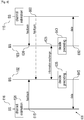
FIGURE 6 illustrates a time diagram for interference avoidance according to embodiments of the present disclosure. The embodiment of the time diagram 600 shown inFIGURE 6 is for illustration only. Other embodiments of the time diagram 600 can be used without departing from the scope of this disclosure. - In an example wherein
SS 116 andSS 115 are edge-cell subscriber stations located in proximity to each other, the communications betweenSS 115 andBS 103 can cause interference in the signals betweenSS 116 andBS 102. Further, the communications betweenSS 116 andBS 102 can cause interference in the signals betweenSS 115 and BS 106. -
SS 116 performs channel estimation instep 605.SS 116 performs measurements based on reference signals received fromBS 102 and fromBS 103.SS 116 divides the codebook and identifies thepreferred set 505 and restrictedset 510. Thereafter,SS 116 sends feedback information (e.g., a precoding matrix information message) toBS 102 instep 615. The feedback information includes the codebook information such as thepreferred set 505, restricted set 510 or both. - Additionally,
SS 115 performs channel estimation in step 610.SS 115 performs measurements based on reference signals received fromBS 103 and fromBS 102.SS 115 divides the codebook and identifies thepreferred set 505 and restrictedset 510. Thereafter,SS 115 sends feedback information toBS 103 instep 620. The feedback information includes the codebook information such as thepreferred set 505, restricted set 510 or both. -
BS 102 andBS 103 exchange information instep 625.BS 102 sends the feedback information received fromSS 116 toBS 103. Additionally,BS 103 sends feedback information received fromSS 115 toBS 102. The exchange of information instep 625 may occur simultaneously or at different times such thatBS 102 sends sends the feedback information received fromSS 116 toBS 103 either before or afterBS 103 sends the feedback information received fromSS 115 toBS 102. - In
step 635,BS 102 decides the precoding to be utilized in future transmissions.BS 102 determines if a codebook vector or matrix identified within the preferred set fromSS 115 can be utilized without significant impairment to the communications toSS 116. For example,BS 102 can determine if an average SNR will pass beyond a base station threshold ζ. Thereafter,BS 102 selects a codebook and transmits data toSS 116 instep 645. - In
step 640,BS 103 decides the precoding to be utilized in future transmissions.BS 103 determines if a codebook vector or matrix identified within the preferred set fromSS 116 can be utilized without significant impairment to the communications toSS 115. For example,BS 103 can determine if an average SNR will pass beyond a base station threshold ζ. Thereafter,BS 103 selects a codebook and transmits data toSS 115 instep 650. - In some embodiments,
SS 115 sends the feedback information directly toBS 102 instep 660. In such embodiments,BS 103 does not need to exchange information withBS 102 instep 625.BS 102 can use the feedback information received fromSS 115 to decided precoding instep 635. However, in such embodiments,BS 102 can still send the feedback information received fromSS 116 toBS 103. - It will be understood that illustration of the sequence of the operations by
SS 116 andSS 115 can occur in any order or simultaneously. For example, the channel estimation performed bySS 115 may occur before, after or concurrently with the channel estimation performed bySS 116. Further, the illustration of the sequence of the operations byBS 102 andBS 103 can occur in any order or simultaneously. For example, the decideprecoding 640 performed byBS 103 may occur before, after or concurrently with the decideprecoding 635 performed byBS 102. -
FIGURE 7 illustrates a process for interference avoidance according to embodiments of the present disclosure. The embodiment of theinterference avoidance process 700 shown inFIGURE 7 is for illustration only. Other embodiments of theinterference avoidance process 700 can be used without departing from the scope of this disclosure. - In some embodiments, interfering base stations can avoid interference with each other by choosing different codebook vectors within a standardized codebook. This is achieved by allowing the base stations to choose codebook vectors or matrices to transmit their own signals in the space which creates little or even no interference to the other cells' subscriber stations in the same bandwidth.
- In
step 705,SS 116 performs channel estimation.SS 116 may be, for example, a cell-edge subscriber station.SS 116 estimates the channel matrix from BS 102 (e.g., the serving base station). Further,SS 116 estimates the channel matrices from BS 103 (e.g., a strong interfering base station).SS 116 estimates the channel matrices fromBS 102 andBS 103, respectively, through reference signals. -
SS 116 generates feedback information instep 710.SS 116 identifies preferred codebook vectors or matrices. Based on the estimated channel matrices,SS 116 searches for a codebook vector or matrix that maximizes a receive signal power forSS 116. Thus,SS 116 generates a precoding vector or matrix for its own serving cell (e.g. from BS 102) to maximize the received power forSS 116. Additionally,SS 116 can search for a codebook vector or matrix that maximizes some other performance measures.SS 116 searches the codebook vector or matrix fromBS 102 together with the codebook vectors or matrices fromBS 103 subject to the configurableparameter threshold ε 462. Thus,SS 116 identifies or calculates a number of precoding vectors or matrices such that, when used byBS 103, an interference in the signal betweenSS 116 andBS 102 will be belowthreshold ε 462. In some embodiments,SS 116 identifies only the codebook vectors or matrices fromBS 103 that will cause an interference in the received signal fromBS 102. For example, the codebook information to each interfering base station can be either the combination of the precoding vectors or matrices that will create interference less than or equal to the threshold ε 462 or the combination of the precoding vectors or matrices that will create interference greater than thethreshold ε 462. In some additional and alternative embodiments,SS 116 divides the standardized codebook into apreferred set 505 and arestricted set 510. - In
step 715,SS 116 sends the feedback information (also referred to as precoding matrix message) toBS 102. The feedback information includes codebook information related to the codebook vectors or matrices. The feedback information is reported by SS 16 toBS 102. Additionally, information related to the average SNR (or some other performance measures) together with the SNR improvement (or some other performance measures) whenBS 103 is using the preferred codebook vectors or matrices are also reported. - For example, for all the channels connected to
SS 116,SS 116 sends feedback information including codebook information related to either the directions of strong eigen-channels or those of the weak eigen-channels.SS 116 sends this codebook information either toBS 102 or toBS 103 directly. - For the system shown in
FIGURES 1A and 1B , the interfering channel matrix received atSS 116 isH 21 140.SS 116 can send the direction of the eigen-channels ofH 21 140 where the corresponding singular value is substantial. Furthermore,SS 116 may also elect to feedback the receive channel vector from each antenna toBS 103 directly or indirectly throughBS 102. For example, for the interferingchannel matrix H 21 140,SS 116 can feedback quantized directions of h 1 ,KhNR , where is defined by Equation 5:
-
SS 116 may also send, directly toBS 103, the feedback information related to the interfering channel gains with or without the scheduling information. For example,SS 116 can send the scheduling information to theBS 103. Upon receiving the scheduling information,BS 103 may get the information about interference level and information related to the channel matrices from previous coordination betweenBS 103 andSS 116 for the particular frequency band. -
BS 102 receives the feedback information instep 720.BS 102 processes the information and identifies that the interfering base station isBS 103. ThenBS 102 forwards the feedback information toBS 103 instep 725. -
BS 103 receives the feedback information fromBS 102 instep 730. In some embodiments,BS 103 receives the feedback information directly fromSS 116 instep 730. - In
steps BS 102 andBS 103 respectively select codebook vectors or matrices for future transmissions. Instep 740, upon receiving feedback information from eitherBS 102 orSS 116,BS 103 chooses a codebook vector or matrix to send toSS 115 (.e.g., the intended subscriber station for BS 103).BS 103 can select the codebook vector or matrix to send toSS 115 based on the feedback information fromSS 116.BS 102 also chooses a codebook vector or matrix to send toSS 116 instep 735. - For example,
BS 103 may choose to restrict the codebook vectors or matrices, orBS 103 can choose the codebook vectors or matrices from the preferred set based on the average SNR values ofSS 115. To be specific,BS 103 may decide the precoding vectors or matrices toSS 115 depending on the performance improvement forSS 116 and whether an average SNR for the communications betweenBS 103 andSS 115 passes beyond a certain base station threshold ζ. As another example, ifBS 103 identifies that one or more of the codebook vectors or matrices in thepreferred set 505 can be used without affecting the SINR of the signal betweenBS 103 andSS 115,BS 103 may select one of the codebook vectors or matrices in the preferred set. Additionally,BS 103 may avoid selection of a codebook vector or matrix in the restricted set if the restricted set is the feedback information that is provided. - In some embodiments,
SS 116 sends a special indicator to enable a dynamic inter-cell interference coordination. This dynamic overload indicator is obtained in the "Feedback Information Generating"step 710 where either all (or most of) the combinations of the codebook vectors or matrices will bring an interference level greater than the threshold ε 462 or all the combinations will produce an interference level smaller than thethreshold ε 462. After obtaining this indicator,BS 102 andBS 103 can jointly perform inter-cell interference coordination to avoid inter-cell interference. - For example,
BS 102schedules SS 116 to another frequency band (or other resource blocks) ifBS 102 receives the dynamic overload indicator fromSS 116 indicating that all (or most of) the combinations of the codebook vectors or matrices cannot bring the interference level to be smaller thanthreshold ε 462. - In some such embodiments, where the SNR between
BS 102 andSS 116 reaches a predetermined level,SS 116 is configured to raise the threshold ε 462 such that all the combinations will produce an interference level smaller than thethreshold ε 462. In some additional and alternative embodiments, where the SNR is above a certain threshold ζ,BS 102 is configured to adjust thethreshold ε 462. In such embodiments,BS 102 can send a separate signal toSS 116 orBS 102 can include the adjustment command within existing signaling betweenBS 102 andSS 116. - In an additional example,
BS 102 may request thatBS 103 not schedule subscriber stations (e.g., SS 115) in the particular frequency bands (resource blocks) upon receiving the dynamic overload indicator fromSS 116. - In some such embodiments,
SS 116 informsBS 102 that all (or most of) the combinations of the codebook vectors or matrices cannot bring the interference level to be smaller thanthreshold ε 462. Thereafter,BS 102 utilizes other means, such as, but not limited to, using a different frequency band, to transmit toSS 116. -
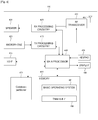
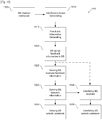
FIGURE 8 illustrates another process for interference avoidance according to embodiments of the present disclosure. The embodiment of theinterference avoidance process 800 shown inFIGURE 8 is for illustration only. Other embodiments of theinterference avoidance process 800 can be used without departing from the scope of this disclosure. - In some embodiments, interfering base stations can avoid interference with each other by choosing different codebook vectors within a standardized codebook. In such embodiments,
BS 102 andBS 103 share information related to all the channel matrices.BS 102 andBS 103 iteratively find good precoding vectors and matrices that avoid interference in the others respective signals. - In
step 805,SS 116 performs channel estimation.SS 116 may be, for example, a cell-edge subscriber station.SS 116 estimates the channel matrix from BS 102 (e.g., the serving base station). Further,SS 116 estimates the channel matrices from BS 103 (e.g., a strong interfering base station).SS 116 estimates the channel matrices fromBS 102 andBS 103, respectively, through reference signals. -
SS 116 generates channel feedback information instep 810 based on the estimated channel matrices.SS 116 sends, toBS 102, channel feedback information related to the channel matrices toBS 102 and the channel matrices toBS 103 instep 815. In some embodiments,SS 116 sends the channel feedback information directly toBS 103 instep 815. - For example, for all the interfering channels connected to
SS 116,SS 116 sends channel feedback information related to either the directions of strong eigen-channels or those of the weak eigen-channels of H H H (where H is the interfering channel matrix). The channel feedback information is sent either toBS 102 or toBS 103 directly. For the system shown inFIGURES 1A and 1B , the interfering channel matrix received atSS 116 is H21. SS 116 can send the direction of the eigen-channels of
- In some additional embodiments,
SS 116 sends quantized information about


-
BS 102 receives and process the channel feedback information received fromSS 116 instep 820.BS 102 processes the channel feedback information and identifies that the interfering base station isBS 103. ThenBS 102 forwards the channel feedback information related to all the channel matrices obtained fromSS 116 toBS 103 instep 825. -
BS 103 receives the channel feedback information fromBS 102 instep 830. In some embodiments,BS 103 receives the channel feedback information directly fromSS 116 instep 830. - In
steps 835,BS 102 andBS 103 respectively iteratively select codebook vectors or matrices for future transmissions.BS 103 andBS 102 iteratively select codebook vectors or matrices for future transmissions independent of each other. Upon receiving information from eitherBS 102 orSS 116,BS 103 chooses a codebook vector or matrix to send to SS 115 (e.g., the intended subscriber station for BS 103).BS 102 also chooses a codebook vector or matrix to send toSS 116. -
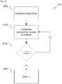
FIGURE 9 illustrates a process for codebook selection according to embodiments of the present disclosure. The embodiment of thecodebook selection process 900 shown inFIGURE 9 is for illustration only. Other embodiments of thecodebook selection process 900 can be used without departing from the scope of this disclosure. - The codebook
selection process step 835 forBS 102 is detailed inFIGURE 9 .BS 102 andBS 103 each apply an iterative method to find the codebook vector or matrix. Without loss of generality, the procedures performed atBS 102 are illustrated. However, it will be understood that the procedures outlined forBS 102 apply equally toBS 103. In such embodiments, the precoding vector or matrix ofBS 102 depends on the precoding vector or matrix of BS 103 (since it will determine the interference caused to SS 116). - In
step 905, an algorithm is initialized.BS 102 computes a possible precoding vector or matrix for BS 103 (let P 2 be the precoding vector or matrix). Also,BS 102 searches the precoding vector or matrix to maximize (or minimize) some performance measures based on the assumption thatBS 103 is using P 2 (let P 1 be the resulting precoding vector or matrix) . For example,BS 102 can search the precoding vector or matrix which maximizes the SNR or throughput. - In
step 910,BS 102 computes a precoding vector and matrix forBS 103 to maximize or minimize some performance measures based on the fact thatBS 102 is using P 1 (update the resulting vector or matrix to P 2).BS 102 further updates its precoding vector or matrix under some performance measures based on the assumption thatBS 103 is using P 2 (update the resulting vector or matrix to P 1). - In
step 915,BS 102 determines if P 1 and P 2 are stable such that a steady state has been achieved. If P 1 and P 2 are not stable, thenBS 102 returns to step 910. If P 1 and P 2 are stable (no change or minimal change), thenBS 102 uses P 1 as the precoding vector or matrix. A similar procedure will take place inBS 103 to find P 2. -
FIGURE 10 illustrates a process for interference avoidance according to embodiments of the present disclosure. The embodiment of theinterference avoidance process 1000 shown inFIGURE 10 is for illustration only. Other embodiments of theinterference avoidance process 1000 can be used without departing from the scope of this disclosure. - In some embodiments,
SS 116 sends an interference avoidance message toBS 102. In such embodiments, the interference avoidance message (IAM) is a value that represents the codebook information, e.g., represents either the preferred set or restricted set of the codebook, or both. For example, the IAM may be a single PMI vector and a variable. In response,BS 103 calculates the preferred set based on the single PMI vector and variable. - In
step 1005,SS 116 performs channel estimation.SS 116 may be, for example, a cell-edge subscriber station.SS 116 estimates the channel matrix from BS 102 (e.g., the serving base station). Further,SS 116 estimates the channel matrices from BS 103 (e.g., a strong interfering base station).SS 116 estimates the channel matrices fromBS 102 andBS 103, respectively, through reference signals. - Then,
BS 102 sends a configuration message toSS 116 instep 1010. The configuration message includes thethreshold ε 462. In some embodiments, the configuration message contains commands forSS 116 to adjust thethreshold ε 462. Threshold ε 462 indicates the interference level atSS 116. In some embodiments, thethreshold ε 462 may represent a target interference level (e.g., tolerable interference level) forSS 116. Receiving the threshold ε 462 bySS 116 triggers precoding vector or matrix reporting for inter-cell interference avoidance (or mitigation). - In
step 1015,SS 116 performs feedback information generation.SS 116 identifies preferred codebook vectors or matrices. Based on the estimated channel matrices,SS 116 searches for a codebook vector or matrix that maximizes a receive signal power forSS 116. Additionally,SS 116 can search for a codebook vector or matrix that maximizes some other performance measures.SS 116 searches the codebook vector or matrix fromBS 102 together with the codebook vectors or matrices fromBS 103 subject to the configurableparameter threshold ε 462. In some embodiments,SS 116 identifies only the codebook vectors or matrices fromBS 103 that will cause an interference in the received signal fromBS 102. For example, the codebook information to each interfering base station can be either the combination of the precoding vectors or matrices that will create interference less than or equal to the threshold ε 462 or the combination of the precoding vectors or matrices that will create interference greater than thethreshold ε 462. In some additional and alternative embodiments,SS 116 divides the standardized codebook into apreferred set 505 and arestricted set 510. From the interference level parameter (i.e., threshold ε 462) obtained fromBS 102,SS 116 also computes the IAM. The IAM indicates the set of recommended or restricted precoding vectors or matrices for the interfering base stations (e.g., BS 103). - In some embodiments,
BS 102 andSS 116 negotiate to feedback the combination of the precoding vectors or matrices that will create interference less than or equal tothreshold ε 462. Additionally, ifSS 116 cannot find any combination of the precoding vectors or matrices that will create interference less than or equal tothreshold ε 462,SS 116 can feedback codebook vector or matrix only forBS 102. - In additional and alternative embodiments,
BS 102 andSS 116 negotiate to feedback the combination of the precoding vectors or matrices that will create interference greater thanthreshold ε 462. Additionally, ifSS 116 cannot find any combination of the precoding vectors or matrices that will create interference greater thanthreshold ε 462,SS 116 can feedback codebook vector or matrix only forBS 102. -
SS 116 sends feedback information toBS 102 instep 1020. The feedback information thatSS 116 sends includes several elements. In some embodiments, the feedback information includes one or more of: - 1. Codebook information, e.g., information related to the codebook vector or matrix which maximizes the receive signal power (or some other performance measures) for BS 102 (e.g., the serving base station) and the information related to the codebook vector or matrix which maximizes the receive signal power (or some other performance measures) for BS 103 (e.g., the interfering base station).
- 2. Information related to the average signal-to-interference-and-noise-ratio (SINR) improvement or some other performance measures. For example, this information can represent the achievable average SINR (or some other performance measures) when
BS 102 is using the precoding vector or matrix feedback fromSS 116. - 3. The corresponding IAM for each of the interfering base stations (e.g., for BS 103). The IAM sent by
SS 116 was computed bySS 116 instep 1015 usingthreshold ε 462. - In some embodiments, the information related to the average SINR improvement is a change in channel quality information (ΔCQI) when
BS 103 is using the recommended set of precoding vectors or matrices. - For example, ΔCQI can be the difference between the expected SINR when
BS 103 is using the recommended set and an expected SINR whenBS 103 is not using the recommended set. - In another example, ΔCQI can be the difference between the worst case SINR when
BS 103 is using the recommended sets and the worst case SINR whenBS 103 is not using the recommended sets. - In yet another example, ΔCQI can be the difference between the worst case SINR when
BS 103 is using the recommended sets and the expected SINR whenBS 103 is not using the recommended sets - In still another example, ΔCQI can be the difference between the expected SINR when
BS 103 is using the recommended sets and the worst case SINR whenBS 103 is not using the recommended sets. - In some embodiments,
SS 116 sends the feedback information directly toBS 103. In such embodiments,SS 116 sends one or more of the codebook information related to codebook vector or matrices for the interference channel, the IAM message indicating the set of recommended (e.g., preferred) or restricted precoding vectors or matrices, and the information related to SINR improvement if the set is applied atBS 103. -
BS 102 receives the feedback information instep 1025.BS 102 processes the information and identifies that the interfering base station isBS 103. ThenBS 102 forwards the feedback information toBS 103 instep 1030. The IAM indicating the recommended (preferred) or the restricted set of the precoding vectors or matrices are reported toBS 103. The corresponding IAMs for different base stations and the SINR (or other performance measures) improvements are forwarded to their respective base stations as well. -
BS 103 receives the feedback information fromBS 102 instep 1035. In some embodiments,BS 103 receives the feedback information directly fromSS 116 instep 1035. - In
steps BS 102 andBS 103 respectively select codebook vectors or matrices for future transmissions. Instep 1045, upon receiving information from eitherBS 102 orSS 116,BS 103 chooses a codebook vector or matrix to send toSS 115 (.e.g., the intended subscriber station for BS 103) based on the feedback information (e.g., one or more of the precoding codebook vector or matrix, the IAM, and the SINR improvement ΔCQI). -
BS 102 also chooses a codebook vector or matrix to send toSS 116 instep 1040.BS 102 may choose a codebook vector or matrix to send toSS 116 based on the feedback information (e.g., one or more of the precoding codebook vector or matrix, the IAM, and the SINR improvement ΔCQI) received from another base station or subscriber station. - In some embodiments, when
BS 103 receives a request fromBS 102,BS 103 chooses to follow the recommendation based the SINR improvement report. OnceBS 103 decides to follow the recommendation,BS 103 may choose a precoding codebook vector or matrix among the set specified by the IAM. In some such embodiments,BS 103 chooses the precoding codebook vector or matrix which maximizes the SINR (or other performance measures) fromBS 103 toSS 115 within the set. - In some embodiments, when
BS 103 receives multiple requests from different base stations,BS 103 may choose to follow a recommendation based on the SINR improvement reports from various base stations. A rank of the requests can be ordered based on ΔCQI and the channel betweenBS 103 andSS 115. - In some embodiments,
BS 102 sends an activation message indicating which subscriber stations are allowed to participate in the interference avoidance process. In such embodiments,BS 102 sends the activation message toSS 116 indicating thatSS 116 is to report feedback information (e.g., reporting the preferred set or restricted set or sending the IAM). In some embodiments,BS 102 sends the activation message to subscriber stations, such asSS 114, indicating that those respective subscriber stations will not participate in interference avoidance.SS 114 may or may not be an edge-cell device. - In some embodiments, by default all subscriber stations participate in the interference avoidance process and report feedback information. In such embodiments,
BS 102 sends a deactivation message to subscriber stations that are not to participate in the interference avoidance process. - In some embodiments, the IAM includes a distance measurement. In such embodiments,
SS 116 generates the IAM based on a distance measure that partitions the precoding codebook vectors into two parts. Part one (preferable set S1 505) contains the codebook vectors or matrices that will cause interference to the receive signals less thanthreshold ε 462; while part two (restricted set S2 510) contains the complement of the first set. The IAM is actually a threshold to distinguish these two sets under different distance measures. Thecodebook partitioner 470 appliesEquation 4 to identify codebook information for the preferred set and for the restricted set. - Again, f(H 21 ,Pi,ε) is a checking function. The checking function checks whether the precoding vector Pi satisfies a specified criteria. If a Pi satisfies the specified criteria, Pi is placed in the
preferred set S 1 505. If Pi does not satisfy the specified criteria, Pi is placed in the restrictedset S 2 510.Equation 4 illustrates the checking function according to one exemplary criterion. InEquation 4, V is a filter atSS 116. - Once the two sets are formed, the
codebook partitioner 470 computes the distance from the elements in one particular set to the precoding codebook vector or matrix that maximizes the interference power (or other performance measure) received atSS 116. An IAM threshold δ can then be used to distinguish these two sets. The IAM threshold δ is a threshold of the distance measurements. - In such manner, the
subscriber station 116 is configured to generate the IAM as compressed feedback information. The compressed feedback information can include a portion of the preferred set and the IAM threshold δ. For example, theSS 116 can generate the compressed feedback information including one vector from the preferred set and IAM threshold δ. In response, either the serving base station or the interfering base station (e.g., which ever receives the compressed feedback information) uses the compressed feedback information to recreate the entire preferred set. Illustration of the compressed feedback signal including the preferred set and IAM threshold δ is for example, embodiments wherein the compressed feedback signal includes the restricted set and the IAM threshold δ can be used without departing from the scope of this disclosure. - For example, a chordal distance can be used to measure the distance between different precoding codebook matrices and set the threshold to be the maximum distance from the elements of preferred set to the precoding matrix which maximizes the interference power.
- In some embodiments,
BS 102 configures the target tolerable interferencelevel threshold ε 462 and a target SINR improvement ΔCQI.BS 102 sends the target tolerable interferencelevel threshold ε 462 and a target SINR improvement ΔCQI toSS 116 in the configuration message discussed hereinabove with respect toFIGURE 10 ,step 1010. Then,SS 116 performs feedback information generation (discussed hereinabove with respect toFIGURE 10 , step 1015). In such embodiments,SS 116 reports the feedback information only if the SINR improvement ΔCQI is greater than the target SINR improvement ΔCQI. IfSS 116 calculates that the SINR improvement ΔCQI is not greater than the target SINR improvement ΔCQI, thenSS 116 does not send the feedback information toBS 102 orBS 103. In some such embodiments, ifSS 116 calculates that the SINR improvement ΔCQI is not greater than the target SINR improvement ΔCQI, thenSS 116 sends a message toBS 102 indicating thatSS 116 cannot meet the target SINR improvement ΔCQI. Accordingly, based on the feedback information related to the average SINR forSS 116,BS 102 may decide to choose different strategies to serveSS 116. For example, when the average SINR (or some other performance measures) is large forSS 116,BS 102 may choose not to do anything. When the average SINR (or some other performance measures) is small forSS 116,BS 102 may choose to rescheduleSS 116 on different resource blocks. - In some embodiments,
SS 116 configures the target tolerable interferencelevel threshold ε 462 and a target channel (e.g., SINR) improvement ΔCQI. In such embodiments,BS 102 sends the activation message, discussed hereinabove, toSS 116 instep 1010. Then,SS 116 performs feedback information generation (discussed hereinabove with respect toFIGURE 10 , step 1015).SS 116 configures the IAM threshold δ locally to be sent toBS 103. For example, IAM threshold δ is computed based on the locally configured tolerable interferencelevel threshold ε 462 through different distance measures. In such embodiments,SS 116 includes a locally configurable target tolerable interferencelevel threshold ε 462. After estimating the channels to BS 103 (e.g., the interfering base stations),SS 116 can partition the precoding codebook vectors and matrices into twosets - In some embodiments, serving base stations configure the target tolerable interference
level threshold ε 462 and a target channel (e.g., SINR) improvement ΔCQI for participating subscriber stations. In such embodiments,BS 102 sends the configuration message and activation message as unified message toSS 116. Then,SS 116 performs feedback information generation (discussed hereinabove with respect toFIGURE 10 , step 1015).SS 116 configures the IAM threshold δ locally to be sent toBS 103.SS 116 reports the feedback information only if the channel (e.g., SINR) improvement ΔCQI is greater than the target channel improvement ΔCQI. IfSS 116 calculates that the channel improvement ΔCQI is not greater than the target channel improvement ΔCQI, thenSS 116 does not send the feedback information toBS 102 orBS 103. In some such embodiments, ifSS 116 calculates that the channel improvement ΔCQI is not greater than the target channel improvement ΔCQI, thenSS 116 sends a message toBS 102 indicating thatSS 116 cannot meet the target channel improvement ΔCQI. Accordingly, based on the feedback information related to the average SINR forSS 116,BS 102 may decide to choose different strategies to serveSS 116. For example, when the average SINR (or some other performance measures) is large forSS 116,BS 102 may choose not to do anything. When the average SINR (or some other channel performance measures) is small forSS 116,BS 102 may choose to rescheduleSS 116 on different resource blocks. In some additional and alternative embodiments,SS 116 sends the feedback information only when both the interference is above the interferencelevel threshold ε 462 and a channel performance improvement is above the target improvement ΔCQI. - In some embodiments, serving base stations transmits only a target channel improvement ΔCQI for its subscriber stations. In such embodiments,
BS 102 sends the configuration message and activation message as unified message toSS 116. Then,SS 116 performs feedback information generation (discussed hereinabove with respect toFIGURE 10 , step 1015).SS 116 configures the IAM threshold δ locally to be sent toBS 103.SS 116 reports the feedback information only if the channel (e.g., SINR) improvement ΔCQI is greater than the target channel improvement ΔCQI. IfSS 116 calculates that the channel improvement ΔCQI is not greater than the target channel improvement ΔCQI, thenSS 116 does not send the feedback information toBS 102 orBS 103. In some such embodiments, ifSS 116 calculates that the channel improvement ΔCQI is not greater than the target SINR improvement ΔCQI, thenSS 116 sends a message toBS 102 indicating thatSS 116 cannot meet the target channel improvement ΔCQI. Accordingly, based on the feedback information related to, for example, the average SINR forSS 116,BS 102 may decide to choose different strategies to serveSS 116. For example, when the average SINR (or some other performance measures) is large forSS 116,BS 102 may choose not to do anything. When the average SINR (or some other performance measures) is small forSS 116,BS 102 may choose to rescheduleSS 116 on different resource blocks. - Although the present disclosure has been described with an exemplary embodiment, various changes and modifications may be suggested to one skilled in the art. It is intended that the present disclosure encompass such changes and modifications as fall within the scope of the appended claims.
Claims (15)
- An apparatus of a user equipment, UE, to be provided a service from a base station, BS, in a wireless communications network, the apparatus comprising:at least one transceiver (410);at least one processor (440) operatively coupled to the at least one transceiver (410),wherein the at least one processor (440) is configured to:receive a mixed signal including a first signal transmitted from the BS and a second signal transmitted from an interfering BS, wherein the second signal is transmitted for another UE;identify the second signal included in the mixed signal;identify a channel gain regarding a channel between the interfering BS and the UE based on the identified second signal;determine, among a plurality of codebooks, at least one codebook for the interfering BS based on the channel gain; andtransmit feedback information for indicating the at least one codebook.
- The apparatus of claim 1, wherein, in order to determine the at least one codebook, the at least one processor (440) is configured to:identify a parameter by using the channel gain and one of the plurality of codebooks; anddetermine the one of the plurality of codebooks as one of the at least one codebook based on comparing the parameter and a threshold.
- The apparatus of claim 2, wherein the at least one processor (440) is configured to:determine the one of the plurality of codebooks as one of the at least one codebook if the parameter exceeds the threshold,wherein one of the at least one codebook is selected for data transmission by the interfering BS.
- The apparatus of claim 2, wherein the at least one processor (440) is configured to:determine the one of the plurality of codebooks as one of the at least one codebook if the parameter is smaller than the threshold,wherein the at least one codebook is excluded among the plurality of codebooks for data transmission by the interfering BS.
- The apparatus of claim 2, wherein the at least one processor (440) is further configured to:
receive a configuration message from the serving base station, the configuration message including the threshold. - The apparatus of claim 1, wherein the at least one processor (440) is further configured to:transmit distance information,wherein a number of the at least one codebook is greater than one, andwherein the distance information indicates a difference one of the at least one codebook and another one of the at least one codebook.
- The apparatus of claim 1, wherein the at least one processor (440) is further configured to:receive, from the interfering BS, data via the channel;wherein the data is pre-coded by a codebook determined based on the at least one codebook.
- A method of for operating a user equipment, UE, to be provided a service from a base station in a wireless communications network, the method comprising:receiving a mixed signal including a first signal transmitted from the BS and a second signal transmitted from an interfering BS, wherein the second signal is transmitted for another UE;identifying the second signal included in the mixed signal;identifying a channel gain regarding a channel between the interfering BS and the UE based on the identified second signal;determining, among a plurality of codebooks, at least one codebook for the interfering BS based on the channel gain;transmitting feedback information for indicating at least one codebook.
- The method of claim 8, wherein determining the at least one codebook comprising:identifying a parameter by using the channel gain and one of the plurality of codebooks; anddetermining the one of the plurality of codebooks as one of the at least one codebook based on comparing the parameter and a threshold.
- The method of claim 9, wherein determining the one of the plurality of codebooks as one of the at least one codebook comprises:determining the one of the plurality of codebooks as one of the at least one codebook if the parameter exceeds the threshold,wherein one of the at least one codebook is selected for data transmission by the interfering BS.
- The method of claim 9, wherein determining the one of the plurality of codebooks as one of the at least one codebook comprises:determining the one of the plurality of codebooks as one of the at least one codebook if the parameter is smaller than the threshold,wherein the at least one codebook is excluded among the plurality of codebooks for data transmission by the interfering BS.
- The method of claim 9, further comprising receiving a configuration message from the serving base station, the configuration message including the threshold.
- The method of claim 8, further comprising
receiving, from interfering BS, data via the channel,
wherein the data is pre-coded by a codebook determined based on the at least one codebook. - The method of claim 8, further comprising:transmitting distance information,wherein a number of the at least one codebook is greater than one, andwherein the distance information indicates a difference one of the at least one codebook and another one of the at least one codebook.
- The method of claim 9,
wherein a number of the at least one codebook is adjusted based on a channel quality regarding the channel by adjusting the threshold.
Priority Applications (1)
| Application Number | Priority Date | Filing Date | Title |
|---|---|---|---|
| EP18205506.1A EP3461207B1 (en) | 2008-06-25 | 2009-06-24 | Inter-cell interference avoidance for downlink transmission |
Applications Claiming Priority (4)
| Application Number | Priority Date | Filing Date | Title |
|---|---|---|---|
| US13309408P | 2008-06-25 | 2008-06-25 | |
| US13384608P | 2008-07-03 | 2008-07-03 | |
| US12/454,531 US8238954B2 (en) | 2008-06-25 | 2009-05-19 | Inter-cell interference avoidance for downlink transmission |
| PCT/KR2009/003396 WO2009157705A2 (en) | 2008-06-25 | 2009-06-24 | Inter-cell interference avoidance for downlink transmission |
Related Child Applications (2)
| Application Number | Title | Priority Date | Filing Date |
|---|---|---|---|
| EP18205506.1A Division EP3461207B1 (en) | 2008-06-25 | 2009-06-24 | Inter-cell interference avoidance for downlink transmission |
| EP18205506.1A Division-Into EP3461207B1 (en) | 2008-06-25 | 2009-06-24 | Inter-cell interference avoidance for downlink transmission |
Publications (3)
| Publication Number | Publication Date |
|---|---|
| EP2292037A2 EP2292037A2 (en) | 2011-03-09 |
| EP2292037A4 EP2292037A4 (en) | 2016-05-04 |
| EP2292037B1 true EP2292037B1 (en) | 2018-12-26 |
Family
ID=41445103
Family Applications (2)
| Application Number | Title | Priority Date | Filing Date |
|---|---|---|---|
| EP18205506.1A Active EP3461207B1 (en) | 2008-06-25 | 2009-06-24 | Inter-cell interference avoidance for downlink transmission |
| EP09770377.1A Not-in-force EP2292037B1 (en) | 2008-06-25 | 2009-06-24 | Inter-cell interference avoidance for downlink transmission |
Family Applications Before (1)
| Application Number | Title | Priority Date | Filing Date |
|---|---|---|---|
| EP18205506.1A Active EP3461207B1 (en) | 2008-06-25 | 2009-06-24 | Inter-cell interference avoidance for downlink transmission |
Country Status (5)
| Country | Link |
|---|---|
| US (1) | US8238954B2 (en) |
| EP (2) | EP3461207B1 (en) |
| KR (1) | KR101578133B1 (en) |
| CN (1) | CN102077637B (en) |
| WO (1) | WO2009157705A2 (en) |
Families Citing this family (30)
| Publication number | Priority date | Publication date | Assignee | Title |
|---|---|---|---|---|
| US6807405B1 (en) | 1999-04-28 | 2004-10-19 | Isco International, Inc. | Method and a device for maintaining the performance quality of a code-division multiple access system in the presence of narrow band interference |
| JP5284459B2 (en) * | 2008-03-28 | 2013-09-11 | エルジー エレクトロニクス インコーポレイティド | Inter-cell interference avoidance method in multi-cell environment |
| US9867203B2 (en) | 2008-07-11 | 2018-01-09 | Qualcomm Incorporated | Synchronous TDM-based communication in dominant interference scenarios |
| US8385483B2 (en) | 2008-11-11 | 2013-02-26 | Isco International, Llc | Self-adaptive digital RF bandpass and bandstop filter architecture |
| EP2192698A1 (en) * | 2008-11-28 | 2010-06-02 | Alcatel Lucent | Selection of Precoding Vectors for Radio Base Station with multiple antennas |
| KR101687589B1 (en) * | 2009-04-24 | 2016-12-20 | 한국전자통신연구원 | Coordinated Communication Methods in Radio Communication Systems and Device for Performing the same |
| US9565011B2 (en) * | 2009-06-04 | 2017-02-07 | Qualcomm Incorporated | Data transmission with cross-subframe control in a wireless network |
| US8718658B2 (en) * | 2009-06-25 | 2014-05-06 | Samsung Electronics Co., Ltd. | Communication system for distributedly managing interference using feedback message |
| US8699610B2 (en) * | 2009-07-30 | 2014-04-15 | Lg Electronics Inc. | Feedback scheme for multi-cell interference mitigation consideration legacy mobile users |
| KR101578650B1 (en) * | 2009-08-18 | 2015-12-21 | 삼성전자주식회사 | Method for trasmitting and receiving data using precoding matrix and terminal of enabling the method |
| US8737505B2 (en) * | 2009-12-15 | 2014-05-27 | Electronics And Telecommunications Research Institute | Method and apparatus of codebook transformation for interference mitigation in codebook-based precoding |
| US8948800B2 (en) * | 2010-03-30 | 2015-02-03 | Qualcomm Incorporated | Systems, apparatuses, and methods to facilitate coordinated scheduling in wireless communication systems |
| US9609536B2 (en) | 2010-04-13 | 2017-03-28 | Qualcomm Incorporated | Measurement of received power and received quality in a wireless communication network |
| US8509194B2 (en) * | 2010-10-26 | 2013-08-13 | Qualcomm Incorporated | Dirty paper coding and reference signal design |
| US8687727B2 (en) * | 2010-11-05 | 2014-04-01 | Intel Corporation | Coordinated multi-point transmission using interference feedback |
| US10531437B2 (en) * | 2012-05-04 | 2020-01-07 | Nokia Solutions And Networks Oy | Configuration of a shared frequency band between wireless communications systems |
| CN102647770B (en) * | 2012-05-07 | 2018-11-09 | 南京中兴软件有限责任公司 | A kind of method of communication, equipment and base station |
| US9780843B2 (en) * | 2012-11-16 | 2017-10-03 | Avago Technologies General Ip (Singapore) Pte. Ltd. | Interference suppression and alignment for cellular networks |
| US9319916B2 (en) | 2013-03-15 | 2016-04-19 | Isco International, Llc | Method and appartus for signal interference processing |
| DE102013113457B4 (en) * | 2013-12-04 | 2017-07-06 | Intel IP Corporation | METHOD AND DEVICE FOR DETECTING AN INTERFERENCE SCENARIOS |
| US9525466B2 (en) * | 2014-04-14 | 2016-12-20 | Lg Electronics Inc. | Method of performing interference cancellation and apparatus therefor |
| US9668223B2 (en) | 2014-05-05 | 2017-05-30 | Isco International, Llc | Method and apparatus for increasing performance of communication links of communication nodes |
| FI3651386T3 (en) | 2015-05-04 | 2023-11-15 | Isco Int Llc | Method and apparatus for increasing the performance of communication paths for communication nodes |
| US9615263B2 (en) * | 2015-05-27 | 2017-04-04 | Telefonaktiebolaget L M Ericsson (Publ) | Method to improve the performance in cell range expansion using location based codebook subset restriction |
| WO2017210056A1 (en) | 2016-06-01 | 2017-12-07 | Isco International, Llc | Method and apparatus for performing signal conditioning to mitigate interference detected in a communication system |
| US10298279B2 (en) | 2017-04-05 | 2019-05-21 | Isco International, Llc | Method and apparatus for increasing performance of communication paths for communication nodes |
| US10812121B2 (en) | 2017-08-09 | 2020-10-20 | Isco International, Llc | Method and apparatus for detecting and analyzing passive intermodulation interference in a communication system |
| US10284313B2 (en) | 2017-08-09 | 2019-05-07 | Isco International, Llc | Method and apparatus for monitoring, detecting, testing, diagnosing and/or mitigating interference in a communication system |
| US11523377B2 (en) * | 2020-02-14 | 2022-12-06 | T-Mobile Usa, Inc. | LTE resource allocation controller |
| EP4197108A1 (en) * | 2021-06-22 | 2023-06-21 | Huawei Technologies Co., Ltd. | Devices and methods for sounding for coordinated beamforming |
Family Cites Families (14)
| Publication number | Priority date | Publication date | Assignee | Title |
|---|---|---|---|---|
| US5768254A (en) * | 1995-09-29 | 1998-06-16 | Lucent Technologies Inc. | Multiple access cellular communication with signal cancellation to reduce co-channel interference |
| US6137991A (en) | 1996-12-19 | 2000-10-24 | Ericsson Telefon Ab L M | Estimating downlink interference in a cellular communications system |
| GB2412036A (en) | 2004-03-08 | 2005-09-14 | Ipwireless Inc | Mitigation of intercell and intracell interference in a cellular communication system |
| KR100969845B1 (en) * | 2005-10-27 | 2010-07-13 | 퀄컴 인코포레이티드 | Precoding for segment sensitive scheduling in wireless communication systems |
| KR100923913B1 (en) * | 2005-11-17 | 2009-10-28 | 삼성전자주식회사 | Apparatus and method for canceling multi user interference |
| US7426198B2 (en) * | 2006-02-06 | 2008-09-16 | Motorola, Inc. | Method and apparatus for performing spatial-division multiple access |
| US7689177B2 (en) * | 2006-05-24 | 2010-03-30 | Samsung Electronics Co., Ltd. | Method and apparatus for transmitting/receiving feedback information and system supporting the same in a multi-user multi-antenna system |
| JP4845640B2 (en) * | 2006-08-23 | 2011-12-28 | 富士通株式会社 | Wireless communication system and wireless communication method |
| US8023457B2 (en) * | 2006-10-02 | 2011-09-20 | Freescale Semiconductor, Inc. | Feedback reduction for MIMO precoded system by exploiting channel correlation |
| CN1972150A (en) * | 2006-10-10 | 2007-05-30 | 中国科学技术大学 | A transmitting and receiving method for limited feedback linear discrete code |
| EP1912347A1 (en) * | 2006-10-11 | 2008-04-16 | Nokia Siemens Networks Gmbh & Co. Kg | Method, mobile station and base station for transmitting data in a mobile communication system |
| US8073069B2 (en) * | 2007-01-05 | 2011-12-06 | Apple Inc. | Multi-user MIMO-SDMA for finite rate feedback systems |
| CN101159462A (en) * | 2007-11-01 | 2008-04-09 | 中国科学技术大学 | Limiting feedback precoding interference suppression method of multi-antenna multi-cell system |
| US8521089B2 (en) * | 2008-03-31 | 2013-08-27 | Intel Corporation | Reducing co-channel interference |
-
2009
- 2009-05-19 US US12/454,531 patent/US8238954B2/en active Active
- 2009-06-24 CN CN200980124586.XA patent/CN102077637B/en active Active
- 2009-06-24 EP EP18205506.1A patent/EP3461207B1/en active Active
- 2009-06-24 EP EP09770377.1A patent/EP2292037B1/en not_active Not-in-force
- 2009-06-24 WO PCT/KR2009/003396 patent/WO2009157705A2/en active Application Filing
- 2009-06-24 KR KR1020117001743A patent/KR101578133B1/en active IP Right Grant
Also Published As
| Publication number | Publication date |
|---|---|
| EP3461207B1 (en) | 2022-08-10 |
| US8238954B2 (en) | 2012-08-07 |
| KR101578133B1 (en) | 2015-12-17 |
| EP3461207A1 (en) | 2019-03-27 |
| CN102077637B (en) | 2014-03-12 |
| EP2292037A2 (en) | 2011-03-09 |
| KR20110025838A (en) | 2011-03-11 |
| EP2292037A4 (en) | 2016-05-04 |
| WO2009157705A3 (en) | 2010-04-15 |
| CN102077637A (en) | 2011-05-25 |
| US20090325590A1 (en) | 2009-12-31 |
| WO2009157705A2 (en) | 2009-12-30 |
Similar Documents
| Publication | Publication Date | Title |
|---|---|---|
| EP2292037B1 (en) | Inter-cell interference avoidance for downlink transmission | |
| EP2291932B1 (en) | Downlink wireless transmission schemes with inter-cell interference mitigation | |
| US8442566B2 (en) | Coordinated multipoint (CoMP) joint transmission using channel information feedback and higher rank dedicated beam-forming | |
| EP2944111B1 (en) | Channel state information feedback design in advanced wireless communication systems | |
| KR101241910B1 (en) | A collaborative mimo using a sounding channel in a multi-cell environment | |
| US9407343B2 (en) | Method and apparatus for mitigating downlink interference | |
| Benjebbour et al. | System-level performance of downlink NOMA combined with SU-MIMO for future LTE enhancements | |
| US8488440B2 (en) | Coordinated linear beamforming in downlink multi-cell wireless networks | |
| US8369429B2 (en) | Method and apparatus for transmitting precoding matrix index in a wireless communication system using CoMP scheme | |
| US9544031B2 (en) | Method of variable rate single user and multi user MIMO feedback for mobile communications system | |
| US8699589B2 (en) | System and method for multi-cell joint codebook feedback in wireless communications systems | |
| US20100273492A1 (en) | Downlink single-user multi-cell mimo systems for interference mitigation | |
| KR20170091664A (en) | Method and apparatus of downlink signaling for partially precoded csi-rs and csi feedback | |
| EP3163767B1 (en) | Method for reporting precoding matrix index for high-frequency band communication in wireless communication system, and apparatus therefor | |
| US9319115B2 (en) | Method for providing precoding information in a multi-user MIMO system | |
| EP2517375B1 (en) | Telecommunication transmission method and system |
Legal Events
| Date | Code | Title | Description |
|---|---|---|---|
| PUAI | Public reference made under article 153(3) epc to a published international application that has entered the european phase |
Free format text: ORIGINAL CODE: 0009012 |
|
| 17P | Request for examination filed |
Effective date: 20101223 |
|
| AK | Designated contracting states |
Kind code of ref document: A2 Designated state(s): AT BE BG CH CY CZ DE DK EE ES FI FR GB GR HR HU IE IS IT LI LT LU LV MC MK MT NL NO PL PT RO SE SI SK TR |
|
| AX | Request for extension of the european patent |
Extension state: AL BA RS |
|
| DAX | Request for extension of the european patent (deleted) | ||
| RAP1 | Party data changed (applicant data changed or rights of an application transferred) |
Owner name: SAMSUNG ELECTRONICS CO., LTD. |
|
| A4 | Supplementary search report drawn up and despatched |
Effective date: 20160405 |
|
| RIC1 | Information provided on ipc code assigned before grant |
Ipc: H04W 24/08 20090101AFI20160330BHEP Ipc: H04B 7/04 20060101ALI20160330BHEP |
|
| STAA | Information on the status of an ep patent application or granted ep patent |
Free format text: STATUS: EXAMINATION IS IN PROGRESS |
|
| 17Q | First examination report despatched |
Effective date: 20180213 |
|
| REG | Reference to a national code |
Ref country code: DE Ref legal event code: R079 Ref document number: 602009056411 Country of ref document: DE Free format text: PREVIOUS MAIN CLASS: H04W0024080000 Ipc: H04W0072080000 |
|
| GRAP | Despatch of communication of intention to grant a patent |
Free format text: ORIGINAL CODE: EPIDOSNIGR1 |
|
| STAA | Information on the status of an ep patent application or granted ep patent |
Free format text: STATUS: GRANT OF PATENT IS INTENDED |
|
| RIC1 | Information provided on ipc code assigned before grant |
Ipc: H04L 1/00 20060101ALI20180702BHEP Ipc: H04B 7/04 20060101ALI20180702BHEP Ipc: H04W 72/08 20090101AFI20180702BHEP |
|
| INTG | Intention to grant announced |
Effective date: 20180731 |
|
| GRAS | Grant fee paid |
Free format text: ORIGINAL CODE: EPIDOSNIGR3 |
|
| GRAA | (expected) grant |
Free format text: ORIGINAL CODE: 0009210 |
|
| STAA | Information on the status of an ep patent application or granted ep patent |
Free format text: STATUS: THE PATENT HAS BEEN GRANTED |
|
| AK | Designated contracting states |
Kind code of ref document: B1 Designated state(s): AT BE BG CH CY CZ DE DK EE ES FI FR GB GR HR HU IE IS IT LI LT LU LV MC MK MT NL NO PL PT RO SE SI SK TR |
|
| REG | Reference to a national code |
Ref country code: GB Ref legal event code: FG4D |
|
| REG | Reference to a national code |
Ref country code: CH Ref legal event code: EP |
|
| REG | Reference to a national code |
Ref country code: AT Ref legal event code: REF Ref document number: 1083180 Country of ref document: AT Kind code of ref document: T Effective date: 20190115 |
|
| REG | Reference to a national code |
Ref country code: DE Ref legal event code: R096 Ref document number: 602009056411 Country of ref document: DE |
|
| REG | Reference to a national code |
Ref country code: IE Ref legal event code: FG4D |
|
| REG | Reference to a national code |
Ref country code: NL Ref legal event code: FP |
|
| PG25 | Lapsed in a contracting state [announced via postgrant information from national office to epo] |
Ref country code: NO Free format text: LAPSE BECAUSE OF FAILURE TO SUBMIT A TRANSLATION OF THE DESCRIPTION OR TO PAY THE FEE WITHIN THE PRESCRIBED TIME-LIMIT Effective date: 20190326 Ref country code: LT Free format text: LAPSE BECAUSE OF FAILURE TO SUBMIT A TRANSLATION OF THE DESCRIPTION OR TO PAY THE FEE WITHIN THE PRESCRIBED TIME-LIMIT Effective date: 20181226 Ref country code: HR Free format text: LAPSE BECAUSE OF FAILURE TO SUBMIT A TRANSLATION OF THE DESCRIPTION OR TO PAY THE FEE WITHIN THE PRESCRIBED TIME-LIMIT Effective date: 20181226 Ref country code: BG Free format text: LAPSE BECAUSE OF FAILURE TO SUBMIT A TRANSLATION OF THE DESCRIPTION OR TO PAY THE FEE WITHIN THE PRESCRIBED TIME-LIMIT Effective date: 20190326 Ref country code: LV Free format text: LAPSE BECAUSE OF FAILURE TO SUBMIT A TRANSLATION OF THE DESCRIPTION OR TO PAY THE FEE WITHIN THE PRESCRIBED TIME-LIMIT Effective date: 20181226 Ref country code: FI Free format text: LAPSE BECAUSE OF FAILURE TO SUBMIT A TRANSLATION OF THE DESCRIPTION OR TO PAY THE FEE WITHIN THE PRESCRIBED TIME-LIMIT Effective date: 20181226 |
|
| REG | Reference to a national code |
Ref country code: LT Ref legal event code: MG4D |
|
| PG25 | Lapsed in a contracting state [announced via postgrant information from national office to epo] |
Ref country code: GR Free format text: LAPSE BECAUSE OF FAILURE TO SUBMIT A TRANSLATION OF THE DESCRIPTION OR TO PAY THE FEE WITHIN THE PRESCRIBED TIME-LIMIT Effective date: 20190327 Ref country code: SE Free format text: LAPSE BECAUSE OF FAILURE TO SUBMIT A TRANSLATION OF THE DESCRIPTION OR TO PAY THE FEE WITHIN THE PRESCRIBED TIME-LIMIT Effective date: 20181226 |
|
| REG | Reference to a national code |
Ref country code: AT Ref legal event code: MK05 Ref document number: 1083180 Country of ref document: AT Kind code of ref document: T Effective date: 20181226 |
|
| PG25 | Lapsed in a contracting state [announced via postgrant information from national office to epo] |
Ref country code: PL Free format text: LAPSE BECAUSE OF FAILURE TO SUBMIT A TRANSLATION OF THE DESCRIPTION OR TO PAY THE FEE WITHIN THE PRESCRIBED TIME-LIMIT Effective date: 20181226 Ref country code: PT Free format text: LAPSE BECAUSE OF FAILURE TO SUBMIT A TRANSLATION OF THE DESCRIPTION OR TO PAY THE FEE WITHIN THE PRESCRIBED TIME-LIMIT Effective date: 20190426 Ref country code: CZ Free format text: LAPSE BECAUSE OF FAILURE TO SUBMIT A TRANSLATION OF THE DESCRIPTION OR TO PAY THE FEE WITHIN THE PRESCRIBED TIME-LIMIT Effective date: 20181226 Ref country code: ES Free format text: LAPSE BECAUSE OF FAILURE TO SUBMIT A TRANSLATION OF THE DESCRIPTION OR TO PAY THE FEE WITHIN THE PRESCRIBED TIME-LIMIT Effective date: 20181226 |
|
| PG25 | Lapsed in a contracting state [announced via postgrant information from national office to epo] |
Ref country code: SK Free format text: LAPSE BECAUSE OF FAILURE TO SUBMIT A TRANSLATION OF THE DESCRIPTION OR TO PAY THE FEE WITHIN THE PRESCRIBED TIME-LIMIT Effective date: 20181226 Ref country code: EE Free format text: LAPSE BECAUSE OF FAILURE TO SUBMIT A TRANSLATION OF THE DESCRIPTION OR TO PAY THE FEE WITHIN THE PRESCRIBED TIME-LIMIT Effective date: 20181226 Ref country code: RO Free format text: LAPSE BECAUSE OF FAILURE TO SUBMIT A TRANSLATION OF THE DESCRIPTION OR TO PAY THE FEE WITHIN THE PRESCRIBED TIME-LIMIT Effective date: 20181226 Ref country code: IS Free format text: LAPSE BECAUSE OF FAILURE TO SUBMIT A TRANSLATION OF THE DESCRIPTION OR TO PAY THE FEE WITHIN THE PRESCRIBED TIME-LIMIT Effective date: 20190426 |
|
| REG | Reference to a national code |
Ref country code: DE Ref legal event code: R097 Ref document number: 602009056411 Country of ref document: DE |
|
| PG25 | Lapsed in a contracting state [announced via postgrant information from national office to epo] |
Ref country code: AT Free format text: LAPSE BECAUSE OF FAILURE TO SUBMIT A TRANSLATION OF THE DESCRIPTION OR TO PAY THE FEE WITHIN THE PRESCRIBED TIME-LIMIT Effective date: 20181226 Ref country code: DK Free format text: LAPSE BECAUSE OF FAILURE TO SUBMIT A TRANSLATION OF THE DESCRIPTION OR TO PAY THE FEE WITHIN THE PRESCRIBED TIME-LIMIT Effective date: 20181226 |
|
| PLBE | No opposition filed within time limit |
Free format text: ORIGINAL CODE: 0009261 |
|
| STAA | Information on the status of an ep patent application or granted ep patent |
Free format text: STATUS: NO OPPOSITION FILED WITHIN TIME LIMIT |
|
| 26N | No opposition filed |
Effective date: 20190927 |
|
| PG25 | Lapsed in a contracting state [announced via postgrant information from national office to epo] |
Ref country code: MC Free format text: LAPSE BECAUSE OF FAILURE TO SUBMIT A TRANSLATION OF THE DESCRIPTION OR TO PAY THE FEE WITHIN THE PRESCRIBED TIME-LIMIT Effective date: 20181226 |
|
| REG | Reference to a national code |
Ref country code: CH Ref legal event code: PL |
|
| PG25 | Lapsed in a contracting state [announced via postgrant information from national office to epo] |
Ref country code: SI Free format text: LAPSE BECAUSE OF FAILURE TO SUBMIT A TRANSLATION OF THE DESCRIPTION OR TO PAY THE FEE WITHIN THE PRESCRIBED TIME-LIMIT Effective date: 20181226 |
|
| REG | Reference to a national code |
Ref country code: BE Ref legal event code: MM Effective date: 20190630 |
|
| PG25 | Lapsed in a contracting state [announced via postgrant information from national office to epo] |
Ref country code: TR Free format text: LAPSE BECAUSE OF FAILURE TO SUBMIT A TRANSLATION OF THE DESCRIPTION OR TO PAY THE FEE WITHIN THE PRESCRIBED TIME-LIMIT Effective date: 20181226 |
|
| PG25 | Lapsed in a contracting state [announced via postgrant information from national office to epo] |
Ref country code: IE Free format text: LAPSE BECAUSE OF NON-PAYMENT OF DUE FEES Effective date: 20190624 |
|
| PG25 | Lapsed in a contracting state [announced via postgrant information from national office to epo] |
Ref country code: BE Free format text: LAPSE BECAUSE OF NON-PAYMENT OF DUE FEES Effective date: 20190630 Ref country code: CH Free format text: LAPSE BECAUSE OF NON-PAYMENT OF DUE FEES Effective date: 20190630 Ref country code: LI Free format text: LAPSE BECAUSE OF NON-PAYMENT OF DUE FEES Effective date: 20190630 Ref country code: LU Free format text: LAPSE BECAUSE OF NON-PAYMENT OF DUE FEES Effective date: 20190624 |
|
| PGFP | Annual fee paid to national office [announced via postgrant information from national office to epo] |
Ref country code: FR Payment date: 20200526 Year of fee payment: 12 Ref country code: DE Payment date: 20200520 Year of fee payment: 12 Ref country code: NL Payment date: 20200521 Year of fee payment: 12 |
|
| PGFP | Annual fee paid to national office [announced via postgrant information from national office to epo] |
Ref country code: GB Payment date: 20200522 Year of fee payment: 12 Ref country code: IT Payment date: 20200622 Year of fee payment: 12 |
|
| PG25 | Lapsed in a contracting state [announced via postgrant information from national office to epo] |
Ref country code: CY Free format text: LAPSE BECAUSE OF FAILURE TO SUBMIT A TRANSLATION OF THE DESCRIPTION OR TO PAY THE FEE WITHIN THE PRESCRIBED TIME-LIMIT Effective date: 20181226 |
|
| PG25 | Lapsed in a contracting state [announced via postgrant information from national office to epo] |
Ref country code: MT Free format text: LAPSE BECAUSE OF FAILURE TO SUBMIT A TRANSLATION OF THE DESCRIPTION OR TO PAY THE FEE WITHIN THE PRESCRIBED TIME-LIMIT Effective date: 20181226 Ref country code: HU Free format text: LAPSE BECAUSE OF FAILURE TO SUBMIT A TRANSLATION OF THE DESCRIPTION OR TO PAY THE FEE WITHIN THE PRESCRIBED TIME-LIMIT; INVALID AB INITIO Effective date: 20090624 |
|
| REG | Reference to a national code |
Ref country code: DE Ref legal event code: R119 Ref document number: 602009056411 Country of ref document: DE |
|
| REG | Reference to a national code |
Ref country code: NL Ref legal event code: MM Effective date: 20210701 |
|
| GBPC | Gb: european patent ceased through non-payment of renewal fee |
Effective date: 20210624 |
|
| PG25 | Lapsed in a contracting state [announced via postgrant information from national office to epo] |
Ref country code: GB Free format text: LAPSE BECAUSE OF NON-PAYMENT OF DUE FEES Effective date: 20210624 Ref country code: DE Free format text: LAPSE BECAUSE OF NON-PAYMENT OF DUE FEES Effective date: 20220101 |
|
| PG25 | Lapsed in a contracting state [announced via postgrant information from national office to epo] |
Ref country code: NL Free format text: LAPSE BECAUSE OF NON-PAYMENT OF DUE FEES Effective date: 20210701 Ref country code: FR Free format text: LAPSE BECAUSE OF NON-PAYMENT OF DUE FEES Effective date: 20210630 |
|
| PG25 | Lapsed in a contracting state [announced via postgrant information from national office to epo] |
Ref country code: MK Free format text: LAPSE BECAUSE OF FAILURE TO SUBMIT A TRANSLATION OF THE DESCRIPTION OR TO PAY THE FEE WITHIN THE PRESCRIBED TIME-LIMIT Effective date: 20181226 |
|
| PG25 | Lapsed in a contracting state [announced via postgrant information from national office to epo] |
Ref country code: IT Free format text: LAPSE BECAUSE OF NON-PAYMENT OF DUE FEES Effective date: 20210624 |