EP2292003B1 - Supporting apparatus of display device - Google Patents
Supporting apparatus of display device Download PDFInfo
- Publication number
- EP2292003B1 EP2292003B1 EP08874719.1A EP08874719A EP2292003B1 EP 2292003 B1 EP2292003 B1 EP 2292003B1 EP 08874719 A EP08874719 A EP 08874719A EP 2292003 B1 EP2292003 B1 EP 2292003B1
- Authority
- EP
- European Patent Office
- Prior art keywords
- sliding
- supporting apparatus
- relative
- sliding member
- unit
- Prior art date
- Legal status (The legal status is an assumption and is not a legal conclusion. Google has not performed a legal analysis and makes no representation as to the accuracy of the status listed.)
- Active
Links
Images


Classifications
-
- F—MECHANICAL ENGINEERING; LIGHTING; HEATING; WEAPONS; BLASTING
- F16—ENGINEERING ELEMENTS AND UNITS; GENERAL MEASURES FOR PRODUCING AND MAINTAINING EFFECTIVE FUNCTIONING OF MACHINES OR INSTALLATIONS; THERMAL INSULATION IN GENERAL
- F16M—FRAMES, CASINGS OR BEDS OF ENGINES, MACHINES OR APPARATUS, NOT SPECIFIC TO ENGINES, MACHINES OR APPARATUS PROVIDED FOR ELSEWHERE; STANDS; SUPPORTS
- F16M11/00—Stands or trestles as supports for apparatus or articles placed thereon ; Stands for scientific apparatus such as gravitational force meters
- F16M11/20—Undercarriages with or without wheels
- F16M11/24—Undercarriages with or without wheels changeable in height or length of legs, also for transport only, e.g. by means of tubes screwed into each other
-
- F—MECHANICAL ENGINEERING; LIGHTING; HEATING; WEAPONS; BLASTING
- F16—ENGINEERING ELEMENTS AND UNITS; GENERAL MEASURES FOR PRODUCING AND MAINTAINING EFFECTIVE FUNCTIONING OF MACHINES OR INSTALLATIONS; THERMAL INSULATION IN GENERAL
- F16M—FRAMES, CASINGS OR BEDS OF ENGINES, MACHINES OR APPARATUS, NOT SPECIFIC TO ENGINES, MACHINES OR APPARATUS PROVIDED FOR ELSEWHERE; STANDS; SUPPORTS
- F16M11/00—Stands or trestles as supports for apparatus or articles placed thereon ; Stands for scientific apparatus such as gravitational force meters
- F16M11/02—Heads
- F16M11/04—Means for attachment of apparatus; Means allowing adjustment of the apparatus relatively to the stand
- F16M11/043—Allowing translations
- F16M11/048—Allowing translations adapted to forward-backward translation movement
-
- F—MECHANICAL ENGINEERING; LIGHTING; HEATING; WEAPONS; BLASTING
- F16—ENGINEERING ELEMENTS AND UNITS; GENERAL MEASURES FOR PRODUCING AND MAINTAINING EFFECTIVE FUNCTIONING OF MACHINES OR INSTALLATIONS; THERMAL INSULATION IN GENERAL
- F16M—FRAMES, CASINGS OR BEDS OF ENGINES, MACHINES OR APPARATUS, NOT SPECIFIC TO ENGINES, MACHINES OR APPARATUS PROVIDED FOR ELSEWHERE; STANDS; SUPPORTS
- F16M11/00—Stands or trestles as supports for apparatus or articles placed thereon ; Stands for scientific apparatus such as gravitational force meters
- F16M11/02—Heads
- F16M11/04—Means for attachment of apparatus; Means allowing adjustment of the apparatus relatively to the stand
- F16M11/06—Means for attachment of apparatus; Means allowing adjustment of the apparatus relatively to the stand allowing pivoting
- F16M11/10—Means for attachment of apparatus; Means allowing adjustment of the apparatus relatively to the stand allowing pivoting around a horizontal axis
-
- F—MECHANICAL ENGINEERING; LIGHTING; HEATING; WEAPONS; BLASTING
- F16—ENGINEERING ELEMENTS AND UNITS; GENERAL MEASURES FOR PRODUCING AND MAINTAINING EFFECTIVE FUNCTIONING OF MACHINES OR INSTALLATIONS; THERMAL INSULATION IN GENERAL
- F16M—FRAMES, CASINGS OR BEDS OF ENGINES, MACHINES OR APPARATUS, NOT SPECIFIC TO ENGINES, MACHINES OR APPARATUS PROVIDED FOR ELSEWHERE; STANDS; SUPPORTS
- F16M13/00—Other supports for positioning apparatus or articles; Means for steadying hand-held apparatus or articles
- F16M13/02—Other supports for positioning apparatus or articles; Means for steadying hand-held apparatus or articles for supporting on, or attaching to, an object, e.g. tree, gate, window-frame, cycle
-
- Y—GENERAL TAGGING OF NEW TECHNOLOGICAL DEVELOPMENTS; GENERAL TAGGING OF CROSS-SECTIONAL TECHNOLOGIES SPANNING OVER SEVERAL SECTIONS OF THE IPC; TECHNICAL SUBJECTS COVERED BY FORMER USPC CROSS-REFERENCE ART COLLECTIONS [XRACs] AND DIGESTS
- Y10—TECHNICAL SUBJECTS COVERED BY FORMER USPC
- Y10S—TECHNICAL SUBJECTS COVERED BY FORMER USPC CROSS-REFERENCE ART COLLECTIONS [XRACs] AND DIGESTS
- Y10S248/00—Supports
- Y10S248/917—Video display screen support
- Y10S248/919—Adjustably orientable video screen support
Definitions
- the present disclosure may relate to a display device, and more particularly, may relate to an apparatus to support a display device.
- Display devices may be used for watching images.
- Flat display devices having an almost two-dimensional flat structure are being widely released. Since the flat display devices are lightweight, the devices may be mounted to walls. Supporting apparatuses for various wall-mount-type display devices are therefore being introduced.
- Such a supporting apparatus may include a fixing unit for fixing (or attaching) to a wall, a device connecting part on which a display device is placed, and a connection unit that connects the fixing unit to the device connecting part.
- the connection unit may include a plurality of links. Through operation of the links, the display device may move back and forth and swivel left and right relative to the wall.
- the links may perform the back-and-forth movement of the display device, and thus stress may concentrate on hinge shafts of the respective links so that the supporting apparatus is susceptible to breakage.
- the links may also overlap each other, and thus a back-and-forth width of the supporting apparatus may be increased, which may increase a distance from the wall to the display device.
- United States Patent Application Publication US 2006/0261227 discloses a universal flat panel display mounting system having a central hub and a plurality of telescoping arms pivotably connected to the hub, the arms coupleable to mount a flat panel display.
- United States Patent Application Publication US 2006/0065795 discloses a support for flat monitors, the support made up of a main pole support supporting a horizontal beam with arms for mounting the flat monitor or directly supporting arms for mounting the flat monitor.
- European Patent Application Publication EP 1 832 801 discloses a supporting device for display units, the supporting device having a stationary member secured to a base and an elevation member moveably coupled to the stationary member, the elevation member supporting a horizontal supporting member with connecting devices to connect to a display unit.
- German patent application DE 10 2004 020 267 A1 relates to a screen for a domestic appliance having a hinge system to allow pull-out and angular turning of the screen from a housing of the domestic appliance.
- the display screen can be moved out of a recess of the housing through a translational movement.
- the screen and two rods are connected via a hinge. Each of the rods is guided by a trough-hole of a respective shaft, which itself is rotatably mounted.
- Embodiments provide a supporting apparatus of a display device, which is adapted to achieve a small size, various install positions, and a simple structure.
- the supporting apparatus of the invention as defined by independent claim 1 comprises a fixing unit having a frame that extends along the fixing unit, and a height adjustment unit adapted to move relative to the fixing unit, wherein the height adjustment unit includes a plurality of operation levers and an elastic member adapted to couple to each of the respective operation levers and to maintain a position of the height adjustment unit relative to the fixing unit.
- the supporting apparatus of the invention further comprises a plurality of device connecting parts to support the display device, and a plurality of coupling units adapted to couple to the height adjustment unit and to each of the device connection parts.
- the fixing part is disposed in a middle part of the supporting apparatus, and the respective sliding units rotate on both sides of the fixing part, so that it is minimized that an install position of the supporting apparatus is limited. That is, the fixing part can be fixed to a narrow wall or a narrow indoor column, and thus, the install position of the supporting apparatus is diversified.
- the device connecting parts move forward through sliding operation of the sliding units, and thus, while the sliding units rotate relative to the height adjustment unit, stress, applied to hinge points of the sliding units, is distributed to the respective sliding members, thereby preventing breakage of the supporting apparatus.
- the height adjustment unit is configured to move up and down relative to the fixing part, and thus a user can conveniently adjust the height of the display device in the state where the display device is placed on the device connecting parts.
- the minimum movement distance of the height adjustment unit corresponds to respective gaps between catch recesses of a frame, and thus a user can precisely adjust the vertical height of the display device to a desired height, thereby meeting the user's taste.
- FIG. 1 is a perspective view illustrating a supporting apparatus of a display device according to an example embodiment. Other embodiments and configurations are also within the scope of the present invention.
- a supporting apparatus 1 of a display device may include a fixing unit 10, a height adjustment unit 20, a plurality of sliding units 30, a plurality of device connecting parts 50, and tilting friction parts 40.
- the fixing unit 10 may be fixed or attached to a mounting position such as a wall.
- the height adjustment unit 20 may be movable up and down relative to the fixing unit 10.
- the sliding units 30 may be rotatably connected to both sides of the height adjustment unit 20.
- the device connecting parts 50 may be respectively rotatable up and down relative to the sliding units 30, and the display device may be placed on seats of the device connecting parts 50.
- the tilting friction parts 40 may be disposed between the sliding units 30 and the device connecting parts 50 and may provide a friction force against an up-and-down tilting movement.
- the height adjustment unit 20 may vertically move along the fixing unit 10, and may be fixed after any movement using a coupling guide of the fixing unit and a movement maintaining device of the height adjustment unit 20. Since the sliding units 30 respectively include a plurality of sliding members, the device connecting parts 50 may be moved back and forth by sliding operation of the sliding members.
- the tilting friction parts 40 may be disposed between the sliding units 30 and the device connecting parts 50, and provide a friction force to maintain a tilting position of the device connecting parts 50. That is, when a user tilts an image display panel, the tilting friction parts 40 may provide friction force to the device connecting parts 50 to maintain the tilting position of the device connecting parts 50 coupled to the image display panel.
- the fixing unit 10 may include a vertically elongated frame 14 that guides vertical movement of the height adjustment unit 20.
- the fixing unit 10 may also include install brackets 11 coupled to upper and lower sides of the frame 14 to be fixed to a wall, for example.
- the install brackets 11 may be provided with a plurality of holes 12 through which a coupling member (including a screw) passes.
- the height adjustment unit 20 may include a movement member 21 that vertically moves along the fixing unit 10, and a movement maintaining device 24 to fix (or maintain) the movement member 21 at a moved position of the movement member 21.
- the sliding units 30 may be rotatably coupled to the both sides of the height adjustment unit 20.
- the fixing unit 10 may be disposed in a middle of the supporting apparatus 1, and the respective sliding units 30 are rotatable left and right relative to the fixing unit 10.
- the fixing unit 10 may be disposed in the middle of the supporting apparatus 1, thereby minimizing a limit of an install position of the supporting apparatus 1. That is, since the fixing unit 10 can be fixed to a narrow wall or a narrow indoor column, the install position of the supporting apparatus 1 may be diversified.
- FIG. 2 is a perspective view illustrating structure of a sliding unit (such as the sliding unit 30) according to an example embodiment.
- FIG. 3 is a cross-sectional view taken along line A-A of FIG. 2 .
- Other embodiments and configurations are also within the scope of the present invention.
- the sliding unit 30 includes a first sliding member 310 rotatably coupled to the height adjustment unit 20, and a second sliding member 330 capable of sliding relative to the first sliding member 310.
- the second sliding member 330 includes a rotation guide 350 to couple to the tilting friction part 40.
- the second sliding member 330 may slide relative to the first sliding member 310 when the device connecting part 50 moves relative to the fixing unit 10.
- the first sliding member 310 includes a sliding guide 314 for guiding the sliding of the second sliding member 330 relative to the first sliding member 310.
- the sliding guide 314 is recessed from an outside of the first sliding member 310 to an inside of the first sliding member 310.
- the sliding guide 314 is disposed in a sliding direction of the second sliding member 330 relative to the first sliding member 310.
- the second sliding member 330 slides into and out of an inner space of the first sliding member 310.
- the second sliding member 330 includes a guide-receiving part 332 for receiving the sliding guide 314.
- the guide-receiving part 332 is recessed in a side surface of the second sliding member 330.
- the shape and size of the guide-receiving part 332 correspond to the shape and size of the sliding guide 314.
- the first sliding member 310 includes a first guide member 320 on the inside thereof.
- the first guide member 320 may improve strength of the first sliding member 310 and may guide the sliding of the second sliding member 330 relative to the first sliding member 310.
- the second sliding member 330 includes a second guide member 340 on an outside thereof, that interacts with the first guide member 320.
- the first guide member 320 may include a plurality of coupling protrusions 322 that are provided on a first side surface of the first guide member 320 and are coupled to the first sliding member 310.
- the first sliding member 310 may include protrusion through holes 312 through which the coupling protrusions 322 may pass.
- a plurality of guide ribs 324 may protrude from a second side surface of the first guide member 320.
- the guide ribs 324 may be spaced from each other in a direction perpendicular to a sliding direction of the second sliding member 330.
- the respective guide ribs 324 may extend in the sliding direction of the second sliding member 330.
- the second guide member 340 may include a plurality of rib insertion grooves 342 into which the respective guide ribs 324 are inserted.
- the first guide member 320 is provided with the guide ribs 324, and the second guide member 340 is provided with the rib insertion grooves 342.
- the first guide member 320 may also be provided with a plurality of rib insertion grooves, and the second guide member 340 may be provided with a plurality of guide ribs.
- the first sliding member 310 may be provided with the first guide member 320 including the guide ribs 324, and the second sliding member 330 may be provided with the second guide member 340 including the rib insertion grooves 342.
- the first sliding member 310 may also be provided with a plurality of protruding guide ribs, and the second sliding member 330 may also be provided with a plurality of recessed rib insertion grooves.
- the sliding guide 314 and a side surface 311 of the first sliding member 310 facing the sliding guide 314 may be coupled with a limit-setting guide 317 that sets a sliding limit of the second sliding member 330 relative to the first sliding member 310.
- the sliding guide 314 and the side surface 311 of the first sliding member 310 respectively include a first through hole 315 and a second through hole 316 that receives the limit-setting guide 317.
- the second sliding member 330 includes an opening 334 that receives the limit-setting guide 317.
- the opening 334 may be elongated in the sliding direction of the second sliding member 330. In a state where the limit-setting guide 317 has passed through the opening 334, the second sliding member 330 may slide relative to the first sliding member 310.
- the limit-setting guide 317 may sequentially penetrate the first through hole 315, the opening 334, and the second through hole 316.
- the limit-setting guide 317 that has passed through the second through hole 316 may be coupled with a fixing member 318 to prevent the limit-setting guide 317 from being removed from the first through hole 315, the second through hole 316, and the opening 334.
- the limit-setting guide 317 may include a screw, and the fixing member 318 may be a nut coupled to the screw.
- the structure of the limit-setting guide 317 and the fixing member 318 is not limited to this structure and configuration.
- the second sliding member 330 may slide by a length of the opening 334. More particularly, the second sliding member 330 may slide by a length of the opening 334 with the left-and-right width of the limit-setting guide 317 subtracted from an entire length of the opening 334.
- the length of the opening 334 may be adjusted according to a kind of a display device, thereby adjusting a forward movement distance of the display device.
- FIGs. 11 and 12 show an image display panel 500 of the display device that moves back and forth.
- the rotation guide 350 may be rotatably coupled to the tilting friction part 40.
- the rotation guide 350 allows the tilting friction part 40 to rotate with respect to the rotation guide 350 so that the display device can move forward while maintaining a constant distance between the device connecting parts 50.
- the tilting friction parts 40 may be rotatable relative to the rotation guides 350.
- the tilting friction parts 40 may rotate relative to the sliding units 30.
- FIG. 4 is a perspective view illustrating structure of a tilting friction part (such as the tilting friction part 40) according to an example embodiment.
- a tilting friction part such as the tilting friction part 40
- Other embodiments and configurations are also within the scope of the present invention.
- the tilting friction part 40 includes a first arc member 410 coupled to the rotation guide 350 (of the sliding unit 30), and a second arc member 420 coupled to the device connecting part 50.
- the second arc member 420 may move relative to the first arc member 410.
- Interfaces of the respective first and second arc members 410 and 420 may be provided with a plurality of friction recesses 412 and 422 having an arc shape, which have an identical center of rotation at a specific position.
- the friction recesses 412 and 422 of the respective arc members 410 and 420 may be fitted onto each other. That is, the respective arc members 410 and 420 may be provided in a concave-convex structure such that protrusions of the first arc member 410 are inserted into the friction recesses 422 of the second arc member 420, and simultaneously protrusions of the second arc member 420 are inserted into the friction recesses 412 of the first arc member 410.
- Such arc members are respectively provided with the corresponding friction recesses 412 and 422, thereby improving a friction force and obtaining a great friction force using a small member. This may reduce the size of components of a supporting apparatus.
- the respective arc members 410 and 420 may be formed of resin. Such resin may reduce noise generated from interfaces of the respective friction recesses 412 and 422 and improve the friction force.
- the second arc member 420 may be coupled to the device connecting part 50 through a coupling member, and the second arc member 420 may be provided with coupling holes 424 for coupling to the coupling member.
- the rotation guide 350 may be provided with a stopper 352 to set a rotation limit of the tilting friction part 40 when the device connecting part 50 moves rearward. As shown in FIG. 4 , in a state where the device connecting part 50 and the sliding unit 30 are parallel to each other, the stopper 352 may come in close contact with a front surface of the first arc member 410 to prevent rotation of the first arc member 410, and thus prevent (or minimize) the device connecting part 50 from moving rearward.
- FIG. 5 is a perspective view illustrating structure of a height adjustment unit according to an example embodiment.
- FIG. 6 is a perspective view illustrating the height adjustment unit 20 of FIG. 5 with the movement member 21 removed.
- FIG. 7 is a perspective view illustrating the height adjustment unit 20 of FIG. 6 with the movement maintaining device 24 released from the frame 14.
- Other embodiments and configurations are also within the scope of the present invention.
- the movement member 21 may vertically slide along the frame 14 while at least partially surrounding the frame 14. In order to prevent the movement member 21 from being removed ahead of the frame 14, the movement member 21 may surround the entire front surface of the frame 14 and at least a portion of a rear surface of the frame 14.
- Both side surfaces and a rear surface of the movement member 21 may be referred to as removal prevention parts for preventing the movement member 21 from being removed ahead of the fixing unit 10.
- the removal prevention parts may guide the movement member 21 to slide relative to the frame 14 that extends along the fixing unit 10.
- the movement maintaining device 24 may be rotatably coupled to an inside of the movement member 21 through a hinge member so as to vertically move together with the movement member 21.
- the movement maintaining device 24 may be coupled to the frame 14 to maintain the movement member 21 relative to the frame 14 (or the fixing unit 10).
- Two sets of coupling parts 22 are respectively disposed on both sides of the movement member 21 to hinge the movement member 21 to the sliding units 30.
- the sliding units 30 may be rotatable back and forth about the coupling parts 22.
- the image display panel 500 disposed ahead of the sliding units 30 may move back or forth.
- a front surface of the movement member 21 may be provided with a plurality of coupling holes 23 through which a coupling member may pass.
- the coupling member may couple the movement maintaining device 24 to the movement member 21 in a state where the movement maintaining device 24 is fixed to the frame 14.
- the movement maintaining device 24 and the frame 14 may be selectively coupled to each other through operation of the movement maintaining device 24.
- the movement maintaining device 24 may be coupled to the movement member 21 in the state where the movement maintaining device 24 is coupled to the frame 14 so as to prevent movement of the movement maintaining device 24, thereby maintaining the state where the movement maintaining device 24 is coupled to the frame 14.
- the movement maintaining device 24 may include a couple of operation levers 240 and an elastic member 248.
- the operation levers 240 may include a first operation lever 240a and a second operation lever 240.
- the operation levers 240a and 240b may face each other.
- Coupling guides 141 are respectively disposed on both sides of the frame 14 such that the operation levers 240 are selectively coupled to the coupling guides 141.
- the coupling guides 141 are disposed in a vertical direction of the frame 14.
- surfaces of the respective coupling guides 141 facing each other may be provided with a plurality of catch recesses 142.
- Outside surfaces of the respective operation levers 240 may be respectively provided with a plurality of catch protrusions 242 inserted into portions of the catch recesses 142.
- Each operation lever 240 may be provided with the catch protrusions 242, and the catch protrusions 242 may be selectively inserted into portions of the catch recesses 142, respectively. As such, the catch protrusions 242 may be inserted into the catch recesses 142, so that the operation levers 240 and the frame 14 are firmly coupled to each other.
- the coupling guides 141 are provided with the catch recesses 142, and the operation levers 240 are provided with the catch protrusions 242 such that the protrusions are respectively disposed between the catch recesses 142, and the recesses are respectively disposed between the catch protrusions 242.
- the coupling guides 141 and the operation levers 240 respectively include concave-convex portions for engaging with each other.
- the elastic member 248 may be provided between the operation levers 240. One end of the elastic member 248 is coupled to the first operation lever 240a and the other end of the elastic member 248 is coupled to the second operation lever 240b.
- the elastic member 248 may apply an elastic force to the respective operation levers 240 in a direction in which the catch protrusions 242 of the respective operation levers 240 are inserted into the catch recesses 142 of the coupling guides 141.
- the operation levers 240 may include pivot-coupling holes 244 coupled to pivots provided to the movement member 21.
- the operation levers 240 may rotate in opposite directions from each other when being provided in a state to allow movement of the height adjustment unit 20 relative to the fixing unit 10. Accordingly, the elastic member 248 may move or rotate each of the levers 240a and 240b such that each of the levers 240a, 240b touches the coupling guide 141.
- Each respective operation lever 240 may be provided with a plurality of coupling holes 246 coupled with the coupling member that has penetrated the coupling holes 23 of the movement member 21.
- each operation lever 240 may be divided into an upper portion coupled to the elastic member 248, and a lower portion provided with the catch protrusions 242 (to be inserted into the catch recesses 142 of the coupling guides 141).
- the elastic force of the elastic member 248 maintains the state where the catch protrusions 242 of the respective operation levers 240 have been inserted in the catch recesses 142. In this state, the height adjustment unit 20 is maintained at a same position relative to the fixing unit 10 (and to the frame 14).
- the operation levers 240 are operated in a direction in which the upper portions of the respective operation levers 240 depart from each other.
- the first operation lever 240a may be pushed to the left side and rotated counter clockwise, and the second operation lever 240b may be pushed to the right side and rotated clockwise.
- the elastic member 248 may be elongated, and the catch protrusions 242 of the respective operation levers 240 may be released from the catch recesses 142 so as to allow the height adjustment unit 20 to vertically move relative to the fixing unit 10.
- the height adjustment unit 20 may be moved to a desired height relative to the fixing unit 10. After that, a force applied to the respective operation levers 240 may be removed, and then a restoring force of the elastic member 248 may cause the upper portions of the respective operation levers 240 to rotate in directions in which the operation levers 240 may be closer to each other. Accordingly, the catch protrusions 242 of the respective operation levers 240 are inserted into the catch recesses 142. The user may couple the coupling member to the respective coupling holes 23 and 246.
- FIGs. 8 to 10 are views illustrating operation of a supporting apparatus according to an example embodiment.
- FIG. 8 is the view illustrating a forward movement operation of a supporting apparatus.
- FIG. 9 is the view illustrating an up-and-down tilting operation of a supporting apparatus.
- FIG. 10 is the view illustrating an up-and-down operation of a supporting apparatus.
- Other embodiments and configurations are also within the scope of the present invention.
- FIGs. 11 and 12 are views illustrating back-and-forth operation of the image display panel 500 coupled to the supporting apparatus.
- the sliding units 30 coupled to both sides of the height adjustment unit 20 may rotate relative to the height adjustment unit 20.
- the device connecting parts 50 may move forward through interaction of the sliding members 310 and 330 respectively forming the sliding units 30. That is, the second sliding members 330 may slide relative to the first sliding members 310.
- the sliding units 30 may operate independently from each other. Thus, a sliding length of the sliding unit 30 coupled to one device connecting part 50 may be different from a sliding length of the sliding unit 30 coupled to the other device connecting part 50.
- a perpendicular distance between one device connecting part 50 and a wall may be different from or equal to a perpendicular distance between the other device connecting part 50 and the wall.
- the respective tilting friction parts 40 may rotate relative to the respective sliding units 30.
- Independent operation of the respective sliding units 30 may allow the display device, installed to the device connecting parts 50, to swivel left and right, for example.
- the sliding units 30 may allow the device connecting parts 50 to move forward, and thus a back-and-forth width of the supporting apparatus may be minimized in the state where the device connecting parts 50 has moved backward as shown in FIG. 1 . That is, since the second sliding members 330 are inserted into and withdrawn from inner spaces of the first sliding members 310, thicknesses of the sliding units 30 can be reduced, and thus the back-and-forth width of the supporting apparatus can be reduced.
- the device connecting parts 50 may move forward through the sliding operation of the sliding units 30, while the sliding units 30 rotate relative to the height adjustment unit 20, stress applied to hinge points of the sliding units 30 may be distributed to the respective sliding members 310 and 330, thereby preventing (or minimizing) breakage of the supporting apparatus.
- the fixing unit 10 may be mounted to a wall or a column having a narrow left-and-right width, so that the install position may be diversified.
- the device connecting parts 50 may be tilted upward or downward relative to the sliding units 30.
- the second arc member 420 may move relative to the first arc member 410.
- a rotation angle may be maintained by the friction force provided by the tilting friction part 40 (i.e., by the friction force between the first arc member 410 and the second arc member 420).
- the display device may be moved forward a predetermined distance before the display device is tilted up and down, thereby preventing a bottom surface of the display device from colliding with the wall during the up-and-down tilting movement.
- FIG. 10 shows that the height adjustment unit 20 has moved downward from the state of FIG. 1 .
- the height adjustment unit 20 may be vertically movable relative to the fixing unit 10, and thus a user can conveniently adjust the height of the display device in the state where the display device is placed on the device connecting parts 50.
- the minimum movement distance of the height adjustment unit 20 may correspond to the respective gaps between the catch recesses 142 of the frame 14, and thus a user can precisely adjust the vertical height of the display device to a desired height, thereby suiting the user's taste.
- the up-and-down tilting, left-and-right swiveling and back-and-forth movements of the display device may be preformed independently from each other.
- a user can independently or simultaneously perform the up-and-down tilting, left-and-right swiveling and back-and-forth movements of the display device.
- the user can watch the flat display device at any position and any angle.
- the sliding unit may include the first sliding member and the second sliding member that is slidable relative to the first sliding member.
- the sliding unit may also include three or more sliding members.
- the first sliding member is coupled to the height adjustment unit; a second sliding member is slidable relative to the first sliding member; and a third sliding member is slidable relative to the second sliding member and is coupled to the tilting friction part.
- the sliding units may also couple the height adjustment unit to the device connecting parts, and thus the sliding units may be referred to as connection units for connecting the height adjustment unit to the device connecting parts.
- Embodiments may provide a supporting apparatus of a display device that is adapted to achieve a small size, various install positions, and a simple structure.
- a supporting apparatus of a display device may include: a fixing unit fixed (or maintained) in a mounting position, sliding units rotatably connected to the fixing unit, and a device connecting part connected to the display device and rotatable relative to the sliding unit, wherein the sliding unit includes a first sliding member rotatable relative to the fixing unit, and a second sliding member slidable relative to the first sliding member.
- a supporting apparatus of a display device may include: a device connecting part configured to support an image display panel; a sliding unit configured to rotate the device connecting part and having a length that varies through sliding of a plurality of sliding members; a height adjustment unit coupled to a side of the sliding unit and that varies a height of the sliding unit; and a fixing unit configured to maintain (or keep) a position of the height adjustment unit.
- a supporting apparatus of a display device may include: a fixing unit configured to have a predetermined position; a height adjustment unit configured to move up and down relative to the fixing unit; connection units respectively connected to both sides of the height adjustment unit; and device connecting parts, on which the display device is placed, connected to the respective connection units.
- the fixing unit may be disposed in a middle part of the supporting apparatus, and the respective sliding units may rotate on both sides of the fixing unit so that it is minimized that an install position of the supporting apparatus is limited. That is, the fixing unit can be fixed to a narrow wall or a narrow indoor column, and thus the install position of the supporting apparatus may be diversified.
- the device connecting parts may move forward through sliding operation of the sliding units.
- stress applied to hinge points of the sliding units may be distributed to the respective sliding members, thereby preventing (or minimizing) breakage of the supporting apparatus.
- the height adjustment unit may be configured to move up and down relative to the fixing unit, and thus a user can conveniently adjust the height of the display device in the state where the display device is placed on the device connecting parts.
- the minimum movement distance of the height adjustment unit may correspond to respective gaps between catch recesses of a frame, and thus a user may precisely adjust the vertical height of the display device to a desired height, thereby meeting the user's taste.
- any reference in this specification to "one embodiment”, “an embodiment”, “example embodiment”, etc. means that a particular feature, structure, or characteristic described in connection with the embodiment is included in at least one embodiment of the invention.
- the appearances of such phrases in various places in the specification are not necessarily all referring to the same embodiment.
Landscapes
- Engineering & Computer Science (AREA)
- General Engineering & Computer Science (AREA)
- Mechanical Engineering (AREA)
- Devices For Indicating Variable Information By Combining Individual Elements (AREA)
Description
- The present disclosure may relate to a display device, and more particularly, may relate to an apparatus to support a display device.
- Display devices may be used for watching images. Flat display devices having an almost two-dimensional flat structure are being widely released. Since the flat display devices are lightweight, the devices may be mounted to walls. Supporting apparatuses for various wall-mount-type display devices are therefore being introduced.
- Such a supporting apparatus may include a fixing unit for fixing (or attaching) to a wall, a device connecting part on which a display device is placed, and a connection unit that connects the fixing unit to the device connecting part. The connection unit may include a plurality of links. Through operation of the links, the display device may move back and forth and swivel left and right relative to the wall.
- The links may perform the back-and-forth movement of the display device, and thus stress may concentrate on hinge shafts of the respective links so that the supporting apparatus is susceptible to breakage.
- The links may also overlap each other, and thus a back-and-forth width of the supporting apparatus may be increased, which may increase a distance from the wall to the display device.
- United States Patent Application Publication
US 2006/0261227 discloses a universal flat panel display mounting system having a central hub and a plurality of telescoping arms pivotably connected to the hub, the arms coupleable to mount a flat panel display. United States Patent Application PublicationUS 2006/0065795 discloses a support for flat monitors, the support made up of a main pole support supporting a horizontal beam with arms for mounting the flat monitor or directly supporting arms for mounting the flat monitor. European PatentApplication Publication EP 1 832 801 discloses a supporting device for display units, the supporting device having a stationary member secured to a base and an elevation member moveably coupled to the stationary member, the elevation member supporting a horizontal supporting member with connecting devices to connect to a display unit. - German
patent application DE 10 2004 020 267 A1 relates to a screen for a domestic appliance having a hinge system to allow pull-out and angular turning of the screen from a housing of the domestic appliance. The display screen can be moved out of a recess of the housing through a translational movement. The screen and two rods are connected via a hinge. Each of the rods is guided by a trough-hole of a respective shaft, which itself is rotatably mounted. - Embodiments provide a supporting apparatus of a display device, which is adapted to achieve a small size, various install positions, and a simple structure.
- The supporting apparatus of the invention as defined by
independent claim 1 comprises a fixing unit having a frame that extends along the fixing unit, and a height adjustment unit adapted to move relative to the fixing unit, wherein the height adjustment unit includes a plurality of operation levers and an elastic member adapted to couple to each of the respective operation levers and to maintain a position of the height adjustment unit relative to the fixing unit. - The supporting apparatus of the invention further comprises a plurality of device connecting parts to support the display device, and a plurality of coupling units adapted to couple to the height adjustment unit and to each of the device connection parts.
- The details of one or more embodiments are set forth in the accompanying drawings and the description below. Other features will be apparent from the description and drawings, and from the claims.
- According to the embodiments, the fixing part is disposed in a middle part of the supporting apparatus, and the respective sliding units rotate on both sides of the fixing part, so that it is minimized that an install position of the supporting apparatus is limited. That is, the fixing part can be fixed to a narrow wall or a narrow indoor column, and thus, the install position of the supporting apparatus is diversified.
- The device connecting parts move forward through sliding operation of the sliding units, and thus, while the sliding units rotate relative to the height adjustment unit, stress, applied to hinge points of the sliding units, is distributed to the respective sliding members, thereby preventing breakage of the supporting apparatus.
- The height adjustment unit is configured to move up and down relative to the fixing part, and thus a user can conveniently adjust the height of the display device in the state where the display device is placed on the device connecting parts.
- Also, the minimum movement distance of the height adjustment unit corresponds to respective gaps between catch recesses of a frame, and thus a user can precisely adjust the vertical height of the display device to a desired height, thereby meeting the user's taste.
-
-
Fig. 1 is a perspective view illustrating a supporting apparatus of a display device according to an embodiment. -
Fig. 2 is a perspective view illustrating structure of a sliding unit according to an embodiment. -
Fig. 3 is a cross-sectional view taken along line A-A ofFig. 2 . -
Fig. 4 is a perspective view illustrating structure of a tilting friction part according to an embodiment. -
Fig. 5 is a perspective view illustrating structure of a height adjustment unit according to an embodiment. -
Fig. 6 is a perspective view illustrating the height adjustment unit ofFig. 5 , with an up-and-down movement part removed. -
Fig. 7 is a perspective view illustrating the height adjustment unit ofFig. 6 , with a fixing unit released from a frame. -
Fig. 8 is a view illustrating a forward movement operation of a supporting apparatus according to an embodiment. -
Fig. 9 is a view illustrating an up-and-down tilting operation of a supporting apparatus. -
Fig. 10 is a view illustrating an up-and-down movement operation of a supporting apparatus. -
Figs. 11 and12 are views illustrating a back-and-forth operation of an image display panel coupled to a supporting apparatus. -
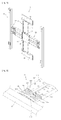
FIG. 1 is a perspective view illustrating a supporting apparatus of a display device according to an example embodiment. Other embodiments and configurations are also within the scope of the present invention. - As shown in
FIG. 1 , a supportingapparatus 1 of a display device may include afixing unit 10, aheight adjustment unit 20, a plurality ofsliding units 30, a plurality ofdevice connecting parts 50, and tiltingfriction parts 40. Thefixing unit 10 may be fixed or attached to a mounting position such as a wall. Theheight adjustment unit 20 may be movable up and down relative to thefixing unit 10. Thesliding units 30 may be rotatably connected to both sides of theheight adjustment unit 20. Thedevice connecting parts 50 may be respectively rotatable up and down relative to thesliding units 30, and the display device may be placed on seats of thedevice connecting parts 50. The tiltingfriction parts 40 may be disposed between thesliding units 30 and thedevice connecting parts 50 and may provide a friction force against an up-and-down tilting movement. - The
height adjustment unit 20 may vertically move along thefixing unit 10, and may be fixed after any movement using a coupling guide of the fixing unit and a movement maintaining device of theheight adjustment unit 20. Since the slidingunits 30 respectively include a plurality of sliding members, thedevice connecting parts 50 may be moved back and forth by sliding operation of the sliding members. - The tilting
friction parts 40 may be disposed between thesliding units 30 and thedevice connecting parts 50, and provide a friction force to maintain a tilting position of thedevice connecting parts 50. That is, when a user tilts an image display panel, the tiltingfriction parts 40 may provide friction force to thedevice connecting parts 50 to maintain the tilting position of thedevice connecting parts 50 coupled to the image display panel. - The
fixing unit 10 may include a verticallyelongated frame 14 that guides vertical movement of theheight adjustment unit 20. Thefixing unit 10 may also includeinstall brackets 11 coupled to upper and lower sides of theframe 14 to be fixed to a wall, for example. Theinstall brackets 11 may be provided with a plurality ofholes 12 through which a coupling member (including a screw) passes. - The
height adjustment unit 20 may include amovement member 21 that vertically moves along thefixing unit 10, and amovement maintaining device 24 to fix (or maintain) themovement member 21 at a moved position of themovement member 21. - The
sliding units 30 may be rotatably coupled to the both sides of theheight adjustment unit 20. Thus, thefixing unit 10 may be disposed in a middle of the supportingapparatus 1, and the respectivesliding units 30 are rotatable left and right relative to thefixing unit 10. - The
fixing unit 10 may be disposed in the middle of the supportingapparatus 1, thereby minimizing a limit of an install position of the supportingapparatus 1. That is, since thefixing unit 10 can be fixed to a narrow wall or a narrow indoor column, the install position of the supportingapparatus 1 may be diversified. -
FIG. 2 is a perspective view illustrating structure of a sliding unit (such as the sliding unit 30) according to an example embodiment.FIG. 3 is a cross-sectional view taken along line A-A ofFIG. 2 . Other embodiments and configurations are also within the scope of the present invention. - As shown in
FIGs. 2 and3 , the slidingunit 30 includes a first slidingmember 310 rotatably coupled to theheight adjustment unit 20, and a second slidingmember 330 capable of sliding relative to the first slidingmember 310. The second slidingmember 330 includes arotation guide 350 to couple to the tiltingfriction part 40. The second slidingmember 330 may slide relative to the first slidingmember 310 when thedevice connecting part 50 moves relative to the fixingunit 10. - The first sliding
member 310 includes a slidingguide 314 for guiding the sliding of the second slidingmember 330 relative to the first slidingmember 310. The slidingguide 314 is recessed from an outside of the first slidingmember 310 to an inside of the first slidingmember 310. The slidingguide 314 is disposed in a sliding direction of the second slidingmember 330 relative to the first slidingmember 310. - At least a portion of the second sliding
member 330 slides into and out of an inner space of the first slidingmember 310. The second slidingmember 330 includes a guide-receivingpart 332 for receiving the slidingguide 314. The guide-receivingpart 332 is recessed in a side surface of the second slidingmember 330. The shape and size of the guide-receivingpart 332 correspond to the shape and size of the slidingguide 314. - The first sliding
member 310 includes afirst guide member 320 on the inside thereof. Thefirst guide member 320 may improve strength of the first slidingmember 310 and may guide the sliding of the second slidingmember 330 relative to the first slidingmember 310. The second slidingmember 330 includes asecond guide member 340 on an outside thereof, that interacts with thefirst guide member 320. - The
first guide member 320 may include a plurality ofcoupling protrusions 322 that are provided on a first side surface of thefirst guide member 320 and are coupled to the first slidingmember 310. The first slidingmember 310 may include protrusion throughholes 312 through which thecoupling protrusions 322 may pass. - A plurality of
guide ribs 324 may protrude from a second side surface of thefirst guide member 320. Theguide ribs 324 may be spaced from each other in a direction perpendicular to a sliding direction of the second slidingmember 330. Therespective guide ribs 324 may extend in the sliding direction of the second slidingmember 330. Thesecond guide member 340 may include a plurality ofrib insertion grooves 342 into which therespective guide ribs 324 are inserted. - In at least one embodiment, the
first guide member 320 is provided with theguide ribs 324, and thesecond guide member 340 is provided with therib insertion grooves 342. However, thefirst guide member 320 may also be provided with a plurality of rib insertion grooves, and thesecond guide member 340 may be provided with a plurality of guide ribs. - In at least one embodiment, the first sliding
member 310 may be provided with thefirst guide member 320 including theguide ribs 324, and the second slidingmember 330 may be provided with thesecond guide member 340 including therib insertion grooves 342. However, the first slidingmember 310 may also be provided with a plurality of protruding guide ribs, and the second slidingmember 330 may also be provided with a plurality of recessed rib insertion grooves. - As shown in
FIG. 3 , the slidingguide 314 and aside surface 311 of the first slidingmember 310 facing the slidingguide 314 may be coupled with a limit-settingguide 317 that sets a sliding limit of the second slidingmember 330 relative to the first slidingmember 310. - The sliding
guide 314 and theside surface 311 of the first slidingmember 310 respectively include a first throughhole 315 and a second throughhole 316 that receives the limit-settingguide 317. - The second sliding
member 330 includes anopening 334 that receives the limit-settingguide 317. Theopening 334 may be elongated in the sliding direction of the second slidingmember 330. In a state where the limit-settingguide 317 has passed through theopening 334, the second slidingmember 330 may slide relative to the first slidingmember 310. - The limit-setting
guide 317 may sequentially penetrate the first throughhole 315, theopening 334, and the second throughhole 316. The limit-settingguide 317 that has passed through the second throughhole 316 may be coupled with a fixingmember 318 to prevent the limit-settingguide 317 from being removed from the first throughhole 315, the second throughhole 316, and theopening 334. For example, the limit-settingguide 317 may include a screw, and the fixingmember 318 may be a nut coupled to the screw. The structure of the limit-settingguide 317 and the fixingmember 318 is not limited to this structure and configuration. - When a
first end 334a of theopening 334 comes in contact with the limit-settingguide 317 while the second slidingmember 330 moves to a left side, the second slidingmember 330 may no longer slide to the left side. On the other hand, when asecond end 334b of theopening 334 comes in contact with the limit-settingguide 317 while the second slidingmember 330 moves to a right side, the second slidingmember 330 may no longer slide to the right side. - The second sliding
member 330 may slide by a length of theopening 334. More particularly, the second slidingmember 330 may slide by a length of theopening 334 with the left-and-right width of the limit-settingguide 317 subtracted from an entire length of theopening 334. The length of theopening 334 may be adjusted according to a kind of a display device, thereby adjusting a forward movement distance of the display device. -
FIGs. 11 and12 show animage display panel 500 of the display device that moves back and forth. - The
rotation guide 350 may be rotatably coupled to the tiltingfriction part 40. When the display device moves forward, therotation guide 350 allows the tiltingfriction part 40 to rotate with respect to therotation guide 350 so that the display device can move forward while maintaining a constant distance between thedevice connecting parts 50. - That is, when the sliding
units 30 slide in a state where the tiltingfriction parts 40 do not rotate relative to the respective slidingunits 30, the distance between thedevice connecting parts 50 may change. In order to maintain the constant distance between the device connecting parts 50 (i.e., at a position fixed to the display image panel), the tiltingfriction parts 40 may be rotatable relative to the rotation guides 350. - Since the
device connecting parts 50 move back and forth in the state the display device is placed on thedevice connecting parts 50, the left-and-right distance between thedevice connecting parts 50 may be maintained constant. As such, to move thedevice connecting parts 50 back and forth in the state where the left-and-right distance between thedevice connecting parts 50 is maintained constant, the tiltingfriction parts 40 may rotate relative to the slidingunits 30. -
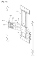
FIG. 4 is a perspective view illustrating structure of a tilting friction part (such as the tilting friction part 40) according to an example embodiment. Other embodiments and configurations are also within the scope of the present invention. - As shown in
FIG. 4 , the tiltingfriction part 40 includes afirst arc member 410 coupled to the rotation guide 350 (of the sliding unit 30), and asecond arc member 420 coupled to thedevice connecting part 50. Thesecond arc member 420 may move relative to thefirst arc member 410. - Interfaces of the respective first and
second arc members respective arc members respective arc members first arc member 410 are inserted into the friction recesses 422 of thesecond arc member 420, and simultaneously protrusions of thesecond arc member 420 are inserted into the friction recesses 412 of thefirst arc member 410. - Such arc members are respectively provided with the corresponding friction recesses 412 and 422, thereby improving a friction force and obtaining a great friction force using a small member. This may reduce the size of components of a supporting apparatus. For example, the
respective arc members - The
second arc member 420 may be coupled to thedevice connecting part 50 through a coupling member, and thesecond arc member 420 may be provided withcoupling holes 424 for coupling to the coupling member. - The
rotation guide 350 may be provided with astopper 352 to set a rotation limit of the tiltingfriction part 40 when thedevice connecting part 50 moves rearward. As shown inFIG. 4 , in a state where thedevice connecting part 50 and the slidingunit 30 are parallel to each other, thestopper 352 may come in close contact with a front surface of thefirst arc member 410 to prevent rotation of thefirst arc member 410, and thus prevent (or minimize) thedevice connecting part 50 from moving rearward. -
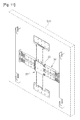
FIG. 5 is a perspective view illustrating structure of a height adjustment unit according to an example embodiment.FIG. 6 is a perspective view illustrating theheight adjustment unit 20 ofFIG. 5 with themovement member 21 removed.FIG. 7 is a perspective view illustrating theheight adjustment unit 20 ofFIG. 6 with themovement maintaining device 24 released from theframe 14. Other embodiments and configurations are also within the scope of the present invention. - As shown in
FIGs. 5 to 7 , themovement member 21 may vertically slide along theframe 14 while at least partially surrounding theframe 14. In order to prevent themovement member 21 from being removed ahead of theframe 14, themovement member 21 may surround the entire front surface of theframe 14 and at least a portion of a rear surface of theframe 14. - Both side surfaces and a rear surface of the
movement member 21 may be referred to as removal prevention parts for preventing themovement member 21 from being removed ahead of the fixingunit 10. The removal prevention parts may guide themovement member 21 to slide relative to theframe 14 that extends along the fixingunit 10. - The
movement maintaining device 24 may be rotatably coupled to an inside of themovement member 21 through a hinge member so as to vertically move together with themovement member 21. - When the height of the
movement member 21 has been adjusted, themovement maintaining device 24 may be coupled to theframe 14 to maintain themovement member 21 relative to the frame 14 (or the fixing unit 10). - Two sets of
coupling parts 22 are respectively disposed on both sides of themovement member 21 to hinge themovement member 21 to the slidingunits 30. Thus, the slidingunits 30 may be rotatable back and forth about thecoupling parts 22. When the slidingunits 30 slide simultaneously with rotating about thecoupling parts 22, theimage display panel 500 disposed ahead of the slidingunits 30 may move back or forth. - A front surface of the
movement member 21 may be provided with a plurality of coupling holes 23 through which a coupling member may pass. The coupling member may couple themovement maintaining device 24 to themovement member 21 in a state where themovement maintaining device 24 is fixed to theframe 14. - That is, the
movement maintaining device 24 and theframe 14 may be selectively coupled to each other through operation of themovement maintaining device 24. Themovement maintaining device 24 may be coupled to themovement member 21 in the state where themovement maintaining device 24 is coupled to theframe 14 so as to prevent movement of themovement maintaining device 24, thereby maintaining the state where themovement maintaining device 24 is coupled to theframe 14. - The
movement maintaining device 24 may include a couple of operation levers 240 and anelastic member 248. The operation levers 240 may include afirst operation lever 240a and asecond operation lever 240. The operation levers 240a and 240b may face each other. - Coupling guides 141 are respectively disposed on both sides of the
frame 14 such that the operation levers 240 are selectively coupled to the coupling guides 141. The coupling guides 141 are disposed in a vertical direction of theframe 14. - Surfaces of the respective coupling guides 141 facing each other may be provided with a plurality of catch recesses 142. Outside surfaces of the respective operation levers 240 may be respectively provided with a plurality of
catch protrusions 242 inserted into portions of the catch recesses 142. - Each
operation lever 240 may be provided with thecatch protrusions 242, and thecatch protrusions 242 may be selectively inserted into portions of the catch recesses 142, respectively. As such, thecatch protrusions 242 may be inserted into the catch recesses 142, so that the operation levers 240 and theframe 14 are firmly coupled to each other. - In this embodiment, the coupling guides 141 are provided with the catch recesses 142, and the operation levers 240 are provided with the
catch protrusions 242 such that the protrusions are respectively disposed between the catch recesses 142, and the recesses are respectively disposed between thecatch protrusions 242. Thus, the coupling guides 141 and the operation levers 240 respectively include concave-convex portions for engaging with each other. - The
elastic member 248 may be provided between the operation levers 240. One end of theelastic member 248 is coupled to thefirst operation lever 240a and the other end of theelastic member 248 is coupled to thesecond operation lever 240b. Theelastic member 248 may apply an elastic force to the respective operation levers 240 in a direction in which thecatch protrusions 242 of the respective operation levers 240 are inserted into the catch recesses 142 of the coupling guides 141. - The operation levers 240 may include pivot-
coupling holes 244 coupled to pivots provided to themovement member 21. The operation levers 240 may rotate in opposite directions from each other when being provided in a state to allow movement of theheight adjustment unit 20 relative to the fixingunit 10. Accordingly, theelastic member 248 may move or rotate each of thelevers levers coupling guide 141. - Each
respective operation lever 240 may be provided with a plurality ofcoupling holes 246 coupled with the coupling member that has penetrated the coupling holes 23 of themovement member 21. - Operation of the
height adjustment unit 20 will now be described. - With respect to the pivot-
coupling holes 244, eachoperation lever 240 may be divided into an upper portion coupled to theelastic member 248, and a lower portion provided with the catch protrusions 242 (to be inserted into the catch recesses 142 of the coupling guides 141). - As shown in
FIG. 6 , when an external force is not applied to the operation levers 240, the elastic force of theelastic member 248 maintains the state where thecatch protrusions 242 of the respective operation levers 240 have been inserted in the catch recesses 142. In this state, theheight adjustment unit 20 is maintained at a same position relative to the fixing unit 10 (and to the frame 14). - For a user to adjust the height of the display device in this state, the operation levers 240 are operated in a direction in which the upper portions of the respective operation levers 240 depart from each other.
- That is, as shown in
FIG. 7 , thefirst operation lever 240a may be pushed to the left side and rotated counter clockwise, and thesecond operation lever 240b may be pushed to the right side and rotated clockwise. When the respective operation levers 240 are operated, theelastic member 248 may be elongated, and thecatch protrusions 242 of the respective operation levers 240 may be released from the catch recesses 142 so as to allow theheight adjustment unit 20 to vertically move relative to the fixingunit 10. - While maintaining the state where the respective operation levers 240 have been rotated, the
height adjustment unit 20 may be moved to a desired height relative to the fixingunit 10. After that, a force applied to the respective operation levers 240 may be removed, and then a restoring force of theelastic member 248 may cause the upper portions of the respective operation levers 240 to rotate in directions in which the operation levers 240 may be closer to each other. Accordingly, thecatch protrusions 242 of the respective operation levers 240 are inserted into the catch recesses 142. The user may couple the coupling member to the respective coupling holes 23 and 246. -
FIGs. 8 to 10 are views illustrating operation of a supporting apparatus according to an example embodiment.FIG. 8 is the view illustrating a forward movement operation of a supporting apparatus.FIG. 9 is the view illustrating an up-and-down tilting operation of a supporting apparatus.FIG. 10 is the view illustrating an up-and-down operation of a supporting apparatus. Other embodiments and configurations are also within the scope of the present invention. -
FIGs. 11 and12 are views illustrating back-and-forth operation of theimage display panel 500 coupled to the supporting apparatus. - As shown in
FIGs. 1 ,8 ,11 and12 , when thedevice connecting parts 50 are pulled forward from the state illustrated inFIG. 1 , the slidingunits 30 coupled to both sides of theheight adjustment unit 20 may rotate relative to theheight adjustment unit 20. - Then, the
device connecting parts 50 may move forward through interaction of the slidingmembers units 30. That is, the second slidingmembers 330 may slide relative to the first slidingmembers 310. - The sliding
units 30 may operate independently from each other. Thus, a sliding length of the slidingunit 30 coupled to onedevice connecting part 50 may be different from a sliding length of the slidingunit 30 coupled to the otherdevice connecting part 50. - A perpendicular distance between one
device connecting part 50 and a wall may be different from or equal to a perpendicular distance between the otherdevice connecting part 50 and the wall. - While the respective
device connecting parts 50 move forward, the respectivetilting friction parts 40 may rotate relative to the respective slidingunits 30. Independent operation of the respective slidingunits 30 may allow the display device, installed to thedevice connecting parts 50, to swivel left and right, for example. - The sliding
units 30 may allow thedevice connecting parts 50 to move forward, and thus a back-and-forth width of the supporting apparatus may be minimized in the state where thedevice connecting parts 50 has moved backward as shown inFIG. 1 . That is, since the second slidingmembers 330 are inserted into and withdrawn from inner spaces of the first slidingmembers 310, thicknesses of the slidingunits 30 can be reduced, and thus the back-and-forth width of the supporting apparatus can be reduced. - Since the
device connecting parts 50 may move forward through the sliding operation of the slidingunits 30, while the slidingunits 30 rotate relative to theheight adjustment unit 20, stress applied to hinge points of the slidingunits 30 may be distributed to the respective slidingmembers - Since the
device connecting parts 50 may move back and forth, and left and right on both sides of the fixingunit 10, the fixingunit 10 may be mounted to a wall or a column having a narrow left-and-right width, so that the install position may be diversified. - As shown in
FIG. 9 , thedevice connecting parts 50 may be tilted upward or downward relative to the slidingunits 30. For example, when thedevice connecting part 50 is tilted downward, thesecond arc member 420 may move relative to thefirst arc member 410. In this case, a rotation angle may be maintained by the friction force provided by the tilting friction part 40 (i.e., by the friction force between thefirst arc member 410 and the second arc member 420). - In the state where the display device is adjacent to the wall, the display device may be moved forward a predetermined distance before the display device is tilted up and down, thereby preventing a bottom surface of the display device from colliding with the wall during the up-and-down tilting movement.
-
FIG. 10 shows that theheight adjustment unit 20 has moved downward from the state ofFIG. 1 . At this point, theheight adjustment unit 20 may be vertically movable relative to the fixingunit 10, and thus a user can conveniently adjust the height of the display device in the state where the display device is placed on thedevice connecting parts 50. - The minimum movement distance of the
height adjustment unit 20 may correspond to the respective gaps between the catch recesses 142 of theframe 14, and thus a user can precisely adjust the vertical height of the display device to a desired height, thereby suiting the user's taste. - The up-and-down tilting, left-and-right swiveling and back-and-forth movements of the display device may be preformed independently from each other. Thus, a user can independently or simultaneously perform the up-and-down tilting, left-and-right swiveling and back-and-forth movements of the display device. As a result, the user can watch the flat display device at any position and any angle.
- The sliding unit may include the first sliding member and the second sliding member that is slidable relative to the first sliding member. However, the sliding unit may also include three or more sliding members. For example, the following configuration may be provided: the first sliding member is coupled to the height adjustment unit; a second sliding member is slidable relative to the first sliding member; and a third sliding member is slidable relative to the second sliding member and is coupled to the tilting friction part.
- The sliding units may also couple the height adjustment unit to the device connecting parts, and thus the sliding units may be referred to as connection units for connecting the height adjustment unit to the device connecting parts.
- Embodiments may provide a supporting apparatus of a display device that is adapted to achieve a small size, various install positions, and a simple structure.
- In an example embodiment, a supporting apparatus of a display device may include: a fixing unit fixed (or maintained) in a mounting position, sliding units rotatably connected to the fixing unit, and a device connecting part connected to the display device and rotatable relative to the sliding unit, wherein the sliding unit includes a first sliding member rotatable relative to the fixing unit, and a second sliding member slidable relative to the first sliding member.
- In another example embodiment, a supporting apparatus of a display device may include: a device connecting part configured to support an image display panel; a sliding unit configured to rotate the device connecting part and having a length that varies through sliding of a plurality of sliding members; a height adjustment unit coupled to a side of the sliding unit and that varies a height of the sliding unit; and a fixing unit configured to maintain (or keep) a position of the height adjustment unit.
- In a further example embodiment, a supporting apparatus of a display device may include: a fixing unit configured to have a predetermined position; a height adjustment unit configured to move up and down relative to the fixing unit; connection units respectively connected to both sides of the height adjustment unit; and device connecting parts, on which the display device is placed, connected to the respective connection units.
- The fixing unit may be disposed in a middle part of the supporting apparatus, and the respective sliding units may rotate on both sides of the fixing unit so that it is minimized that an install position of the supporting apparatus is limited. That is, the fixing unit can be fixed to a narrow wall or a narrow indoor column, and thus the install position of the supporting apparatus may be diversified.
- The device connecting parts may move forward through sliding operation of the sliding units. Thus, while the sliding units rotate relative to the height adjustment unit, stress applied to hinge points of the sliding units may be distributed to the respective sliding members, thereby preventing (or minimizing) breakage of the supporting apparatus.
- The height adjustment unit may be configured to move up and down relative to the fixing unit, and thus a user can conveniently adjust the height of the display device in the state where the display device is placed on the device connecting parts.
- The minimum movement distance of the height adjustment unit may correspond to respective gaps between catch recesses of a frame, and thus a user may precisely adjust the vertical height of the display device to a desired height, thereby meeting the user's taste.
- Any reference in this specification to "one embodiment", "an embodiment", "example embodiment", etc., means that a particular feature, structure, or characteristic described in connection with the embodiment is included in at least one embodiment of the invention. The appearances of such phrases in various places in the specification are not necessarily all referring to the same embodiment. Further, when a particular feature, structure, or characteristic is described in connection with any embodiment, it is submitted that it is within the purview of one skilled in the art to effect such feature, structure, or characteristic in connection with other ones of the embodiments.
Claims (14)
- A supporting apparatus of a display device, the apparatus comprising:- a fixing unit (10) maintaining a mounted position and disposed in the middle of the supporting apparatus,- two sliding units (30) disposed left and right of the fixing unit, wherein each sliding unit (30) is adapted to rotate back and forth relative to the fixing unit (10), and wherein each of the sliding units (30) includes a first sliding member (310) adapted to rotate back and forth relative to the fixing unit, and a second sliding member (330) sliding relative to the first sliding member; and- two device connecting parts (50) each adapted to couple to the display device, wherein each of the device connecting parts (50) is rotatably coupled to a respective second sliding member (330) of the two sliding units (30), characterized in that, in use, when being fixed to the display device each of the device connecting parts (50) moves back and forth relative to the fixing unit (10) by a sliding operation of the first and second sliding members and a simultaneous back and forth rotation operation of the first sliding member (310).
- The supporting apparatus according to claim 1,
wherein the fixing unit (10) maintains the mounted position on a wall, and wherein the back and forth movement is a movement in which a distance between the respective device connecting part (50) and the wall changes. - The supporting apparatus according to claim 1,
wherein a portion of the second sliding member (330) slides into the first sliding member (310). - The supporting apparatus according to claim 1,
wherein the first sliding member (310) includes a sliding guide (314) to guide sliding of the second sliding member (330) relative to the first sliding member, and the second sliding member (330) includes a guide-receiving part (332) adapted to receive the sliding guide (314). - The supporting apparatus according to claim 1, wherein a first one of the sliding units (30) further includes a limit-setting member (317) adapted to set a sliding limit of the second sliding member (330) relative to the first sliding member (310).
- The supporting apparatus according to claim 5, wherein the second sliding member (330) includes an opening (334) to receive the limit-setting member (317), and the opening (334) is elongated along a sliding direction of the second sliding member (330) relative to the first sliding member (310).
- The supporting apparatus according to claim 6, wherein the first sliding member (310) includes a through hole (316) to receive the limit-setting member (317), and wherein the limit-setting member (317) is adapted to pass through both the through hole and the opening.
- The supporting apparatus according to claim 1, further comprising:- a height adjustment unit (20) adapted to move relative to the fixing unit (10), wherein a first one of the sliding units (30) is rotatably coupled to one side of the height adjustment unit (20), and a second one of the sliding units (30) is rotatably coupled to another side of the height adjustment unit (20).
- The supporting apparatus according to claim 8,
the first sliding member (310) adapted to rotate back and forth relative to the height adjustment unit (20). - The supporting apparatus according to claim 8,
wherein the height adjustment unit (20) comprises:- a movement member (21) adapted to move along a frame of the fixing unit (10),- two operation levers (240) adapted to couple to the movement member (21); and- an elastic member (248) adapted to rotate each of the levers such that the levers contact the frame (14). - The supporting apparatus according to claim 10, wherein the frame includes coupling guides provided with concave-convex portions to selectively couple to concave-convex portions of the operational levers based on the elastic member.
- The supporting apparatus according to claim 10,
wherein the operation levers are adapted to rotate in opposite directions from each other when being provided into a state to allow movement of the height adjustment unit relative to the fixing unit, and/or
wherein the elastic member is adapted to apply an elastic force to each of the respective operation levers. - The supporting apparatus according to claim 1, further comprising:- a tilting friction part (40) between each of the sliding units (30) and the respective device connecting part (50) to allow the device connecting part (50) to be moved relative to the respective sliding unit (30),wherein the tilting friction part (40) is rotatable relative to the respective sliding unit (30).
- The supporting apparatus according to claim 13, wherein the tilting friction part comprises:- a first arc member (410) coupled to the respective sliding unit; and- a second arc member (420) coupled to the respective device connecting part (50) and to move relative to the first arc member (410).
Applications Claiming Priority (3)
| Application Number | Priority Date | Filing Date | Title |
|---|---|---|---|
| KR1020080056243A KR101456713B1 (en) | 2008-06-16 | 2008-06-16 | Mounting apparatus of display device |
| KR1020080056244A KR101400552B1 (en) | 2008-06-16 | 2008-06-16 | Mounting apparatus of display device |
| PCT/KR2008/007807 WO2009154337A1 (en) | 2008-06-16 | 2008-12-30 | Supporting apparatus of display device |
Publications (3)
| Publication Number | Publication Date |
|---|---|
| EP2292003A1 EP2292003A1 (en) | 2011-03-09 |
| EP2292003A4 EP2292003A4 (en) | 2011-06-29 |
| EP2292003B1 true EP2292003B1 (en) | 2015-10-14 |
Family
ID=41413879
Family Applications (1)
| Application Number | Title | Priority Date | Filing Date |
|---|---|---|---|
| EP08874719.1A Active EP2292003B1 (en) | 2008-06-16 | 2008-12-30 | Supporting apparatus of display device |
Country Status (4)
| Country | Link |
|---|---|
| US (1) | US7918428B2 (en) |
| EP (1) | EP2292003B1 (en) |
| CN (1) | CN102067588B (en) |
| WO (1) | WO2009154337A1 (en) |
Cited By (1)
| Publication number | Priority date | Publication date | Assignee | Title |
|---|---|---|---|---|
| EP4253821A4 (en) * | 2021-05-31 | 2024-06-26 | Samsung Electronics Co., Ltd. | Wall mount and display apparatus having same |
Families Citing this family (20)
| Publication number | Priority date | Publication date | Assignee | Title |
|---|---|---|---|---|
| US8196760B1 (en) * | 2008-12-16 | 2012-06-12 | Peerless Industries, Inc. | Adjustable display mount |
| CN102235567A (en) * | 2010-04-23 | 2011-11-09 | 鸿富锦精密工业(深圳)有限公司 | Display device fixing frame |
| KR101666901B1 (en) * | 2010-07-20 | 2016-10-17 | 엘지전자 주식회사 | A refrigerator |
| CN102413647A (en) * | 2010-09-21 | 2012-04-11 | 昌硕科技(上海)有限公司 | Supporting module, and electronic device applying same |
| TWM423425U (en) * | 2011-09-16 | 2012-02-21 | Wistron Corp | Frame assembly and panel device therewith |
| WO2013093203A1 (en) * | 2011-12-19 | 2013-06-27 | Hidden View Oy | An arrangement for fastening elements to a wall |
| CN103511815B (en) * | 2012-06-28 | 2015-05-20 | 名硕电脑(苏州)有限公司 | Touch drawing board system and fixing module thereof |
| TWI524771B (en) * | 2012-08-14 | 2016-03-01 | 建碁股份有限公司 | Monitor supporting module |
| US9844265B2 (en) * | 2013-08-30 | 2017-12-19 | Echostar Technologies L.L.C. | Adjustable television nook mount |
| CN105020545B (en) * | 2014-04-24 | 2017-11-03 | 深圳Tcl新技术有限公司 | Flat-panel monitor and its mounting seat |
| US9655258B2 (en) * | 2014-05-30 | 2017-05-16 | Lg Electronics Inc. | Display device |
| KR102269968B1 (en) | 2014-12-08 | 2021-06-28 | 엘지전자 주식회사 | Display apparatus |
| TWI547172B (en) * | 2014-09-03 | 2016-08-21 | 鴻海精密工業股份有限公司 | Mounting apparatus for screens |
| US9797410B1 (en) * | 2015-02-17 | 2017-10-24 | Lawrence Tucker | Adjustable wall mounted fan |
| JP6690174B2 (en) * | 2015-09-30 | 2020-04-28 | ヤマハ株式会社 | Foot pedal device for drums |
| US10317006B2 (en) * | 2015-10-14 | 2019-06-11 | Wirepath Home Systems, Llc | Display mounts and related assemblies and methods |
| US10538962B2 (en) * | 2016-06-16 | 2020-01-21 | Hall Labs Llc | Easy installation headrail assembly |
| US10436381B2 (en) * | 2017-10-23 | 2019-10-08 | Qingdao Hisense Laser Display Co., Ltd. | Wall-hung bracket for projection screen |
| CN112616281B (en) * | 2020-12-25 | 2022-04-22 | 潍坊万德智能科技有限公司 | Industrial Internet of things data acquisition equipment based on 5G network |
| CN116147074B (en) * | 2021-11-19 | 2026-01-23 | 宁波奥克斯电气有限公司 | Air conditioner cabinet unit |
Citations (1)
| Publication number | Priority date | Publication date | Assignee | Title |
|---|---|---|---|---|
| DE102004020267A1 (en) * | 2004-04-26 | 2005-11-24 | BSH Bosch und Siemens Hausgeräte GmbH | An indicator screen for a domestic appliance has a hinge system to allow pull-out and angular turning of the screen from the housing |
Family Cites Families (10)
| Publication number | Priority date | Publication date | Assignee | Title |
|---|---|---|---|---|
| KR100377629B1 (en) * | 2001-06-05 | 2003-03-26 | 엘지전자 주식회사 | Grade control apparatus of display set for tepestry |
| KR20020035062A (en) * | 2002-04-09 | 2002-05-09 | 민정 | a device for a wall television which can regulate the width |
| US20060065795A1 (en) | 2004-09-30 | 2006-03-30 | Compx International | Support for flat monitors |
| US7600728B2 (en) * | 2005-04-28 | 2009-10-13 | Bretford Manufacturing, Inc. | Universal mounting system for a flat panel display |
| DE202005009133U1 (en) * | 2005-06-10 | 2005-10-20 | Gerhard, Markus | Flat television screen mount has telescopic U shaped bracket holding it in front of flue above wall hearth |
| KR20070022911A (en) * | 2005-08-22 | 2007-02-28 | 주식회사 대우일렉트로닉스 | Retention Bracket for Wall-Mounted Display Unit |
| KR20070084650A (en) * | 2006-02-21 | 2007-08-27 | 삼성전자주식회사 | Stand for display device and display device having same |
| KR20070091467A (en) | 2006-03-06 | 2007-09-11 | 삼성전자주식회사 | Supporting device for display device |
| KR101253569B1 (en) * | 2006-05-09 | 2013-04-11 | 삼성전자주식회사 | Supporting device for display device |
| KR100793754B1 (en) * | 2006-07-07 | 2008-01-10 | 엘지전자 주식회사 | Video display device |
-
2008
- 2008-12-30 EP EP08874719.1A patent/EP2292003B1/en active Active
- 2008-12-30 WO PCT/KR2008/007807 patent/WO2009154337A1/en not_active Ceased
- 2008-12-30 CN CN2008801298542A patent/CN102067588B/en active Active
-
2009
- 2009-01-07 US US12/350,018 patent/US7918428B2/en active Active
Patent Citations (1)
| Publication number | Priority date | Publication date | Assignee | Title |
|---|---|---|---|---|
| DE102004020267A1 (en) * | 2004-04-26 | 2005-11-24 | BSH Bosch und Siemens Hausgeräte GmbH | An indicator screen for a domestic appliance has a hinge system to allow pull-out and angular turning of the screen from the housing |
Cited By (1)
| Publication number | Priority date | Publication date | Assignee | Title |
|---|---|---|---|---|
| EP4253821A4 (en) * | 2021-05-31 | 2024-06-26 | Samsung Electronics Co., Ltd. | Wall mount and display apparatus having same |
Also Published As
| Publication number | Publication date |
|---|---|
| US20090308999A1 (en) | 2009-12-17 |
| CN102067588B (en) | 2013-04-24 |
| EP2292003A4 (en) | 2011-06-29 |
| EP2292003A1 (en) | 2011-03-09 |
| WO2009154337A1 (en) | 2009-12-23 |
| US7918428B2 (en) | 2011-04-05 |
| CN102067588A (en) | 2011-05-18 |
Similar Documents
| Publication | Publication Date | Title |
|---|---|---|
| EP2292003B1 (en) | Supporting apparatus of display device | |
| EP1742469B1 (en) | Supporting apparatus for display device | |
| KR100991782B1 (en) | Wall Mount Device for Display Unit | |
| US8317146B2 (en) | Supporting device and dual display unit having the same | |
| KR101135902B1 (en) | Supporting apparatus for display | |
| KR102736745B1 (en) | Display apparatus | |
| KR100609852B1 (en) | Display device | |
| KR20060016664A (en) | Monitor device | |
| CN101403937A (en) | Supporting device and dual display unit having the same | |
| KR100526598B1 (en) | Wall Mounting Type Speaker Assembly | |
| KR101456713B1 (en) | Mounting apparatus of display device | |
| KR100293037B1 (en) | Tilting device for PDP television | |
| KR20100012517A (en) | Mounting apparatus of display device | |
| KR101400552B1 (en) | Mounting apparatus of display device | |
| KR100545604B1 (en) | Mounting structure of flat panel display device | |
| KR20100081182A (en) | Supporting apparatus for display device | |
| KR200364211Y1 (en) | hinge unit of display equipment | |
| KR101353482B1 (en) | Stand and Electronic Equipment having it | |
| KR102941311B1 (en) | slide wall mount | |
| WO2007037565A1 (en) | Angle adjustment apparatus of display device | |
| KR100607207B1 (en) | Wall Mount Angle Adjuster | |
| KR100257727B1 (en) | Pdp watching direction control device | |
| KR100714225B1 (en) | Panel Display Tilting Wall Mount | |
| JP2011048115A (en) | Device for support of display panel | |
| KR101480548B1 (en) | Stand for display device |
Legal Events
| Date | Code | Title | Description |
|---|---|---|---|
| PUAI | Public reference made under article 153(3) epc to a published international application that has entered the european phase |
Free format text: ORIGINAL CODE: 0009012 |
|
| 17P | Request for examination filed |
Effective date: 20101203 |
|
| AK | Designated contracting states |
Kind code of ref document: A1 Designated state(s): AT BE BG CH CY CZ DE DK EE ES FI FR GB GR HR HU IE IS IT LI LT LU LV MC MT NL NO PL PT RO SE SI SK TR |
|
| AX | Request for extension of the european patent |
Extension state: AL BA MK RS |
|
| RIN1 | Information on inventor provided before grant (corrected) |
Inventor name: KIM, TAE-GEWN Inventor name: KIM, KYUNG-WOOK Inventor name: KIM, BYUNG-HEE |
|
| A4 | Supplementary search report drawn up and despatched |
Effective date: 20110601 |
|
| DAX | Request for extension of the european patent (deleted) | ||
| 17Q | First examination report despatched |
Effective date: 20120914 |
|
| GRAP | Despatch of communication of intention to grant a patent |
Free format text: ORIGINAL CODE: EPIDOSNIGR1 |
|
| INTG | Intention to grant announced |
Effective date: 20150512 |
|
| GRAS | Grant fee paid |
Free format text: ORIGINAL CODE: EPIDOSNIGR3 |
|
| GRAA | (expected) grant |
Free format text: ORIGINAL CODE: 0009210 |
|
| AK | Designated contracting states |
Kind code of ref document: B1 Designated state(s): AT BE BG CH CY CZ DE DK EE ES FI FR GB GR HR HU IE IS IT LI LT LU LV MC MT NL NO PL PT RO SE SI SK TR |
|
| REG | Reference to a national code |
Ref country code: GB Ref legal event code: FG4D |
|
| REG | Reference to a national code |
Ref country code: AT Ref legal event code: REF Ref document number: 755840 Country of ref document: AT Kind code of ref document: T Effective date: 20151015 Ref country code: CH Ref legal event code: EP |
|
| REG | Reference to a national code |
Ref country code: IE Ref legal event code: FG4D |
|
| REG | Reference to a national code |
Ref country code: DE Ref legal event code: R096 Ref document number: 602008040722 Country of ref document: DE |
|
| REG | Reference to a national code |
Ref country code: FR Ref legal event code: PLFP Year of fee payment: 8 |
|
| REG | Reference to a national code |
Ref country code: NL Ref legal event code: MP Effective date: 20151014 |
|
| REG | Reference to a national code |
Ref country code: LT Ref legal event code: MG4D |
|
| REG | Reference to a national code |
Ref country code: AT Ref legal event code: MK05 Ref document number: 755840 Country of ref document: AT Kind code of ref document: T Effective date: 20151014 |
|
| PG25 | Lapsed in a contracting state [announced via postgrant information from national office to epo] |
Ref country code: IS Free format text: LAPSE BECAUSE OF FAILURE TO SUBMIT A TRANSLATION OF THE DESCRIPTION OR TO PAY THE FEE WITHIN THE PRESCRIBED TIME-LIMIT Effective date: 20160214 Ref country code: IT Free format text: LAPSE BECAUSE OF FAILURE TO SUBMIT A TRANSLATION OF THE DESCRIPTION OR TO PAY THE FEE WITHIN THE PRESCRIBED TIME-LIMIT Effective date: 20151014 Ref country code: NL Free format text: LAPSE BECAUSE OF FAILURE TO SUBMIT A TRANSLATION OF THE DESCRIPTION OR TO PAY THE FEE WITHIN THE PRESCRIBED TIME-LIMIT Effective date: 20151014 Ref country code: ES Free format text: LAPSE BECAUSE OF FAILURE TO SUBMIT A TRANSLATION OF THE DESCRIPTION OR TO PAY THE FEE WITHIN THE PRESCRIBED TIME-LIMIT Effective date: 20151014 Ref country code: HR Free format text: LAPSE BECAUSE OF FAILURE TO SUBMIT A TRANSLATION OF THE DESCRIPTION OR TO PAY THE FEE WITHIN THE PRESCRIBED TIME-LIMIT Effective date: 20151014 Ref country code: LT Free format text: LAPSE BECAUSE OF FAILURE TO SUBMIT A TRANSLATION OF THE DESCRIPTION OR TO PAY THE FEE WITHIN THE PRESCRIBED TIME-LIMIT Effective date: 20151014 Ref country code: NO Free format text: LAPSE BECAUSE OF FAILURE TO SUBMIT A TRANSLATION OF THE DESCRIPTION OR TO PAY THE FEE WITHIN THE PRESCRIBED TIME-LIMIT Effective date: 20160114 |
|
| PG25 | Lapsed in a contracting state [announced via postgrant information from national office to epo] |
Ref country code: AT Free format text: LAPSE BECAUSE OF FAILURE TO SUBMIT A TRANSLATION OF THE DESCRIPTION OR TO PAY THE FEE WITHIN THE PRESCRIBED TIME-LIMIT Effective date: 20151014 Ref country code: FI Free format text: LAPSE BECAUSE OF FAILURE TO SUBMIT A TRANSLATION OF THE DESCRIPTION OR TO PAY THE FEE WITHIN THE PRESCRIBED TIME-LIMIT Effective date: 20151014 Ref country code: GR Free format text: LAPSE BECAUSE OF FAILURE TO SUBMIT A TRANSLATION OF THE DESCRIPTION OR TO PAY THE FEE WITHIN THE PRESCRIBED TIME-LIMIT Effective date: 20160115 Ref country code: PT Free format text: LAPSE BECAUSE OF FAILURE TO SUBMIT A TRANSLATION OF THE DESCRIPTION OR TO PAY THE FEE WITHIN THE PRESCRIBED TIME-LIMIT Effective date: 20160215 Ref country code: SE Free format text: LAPSE BECAUSE OF FAILURE TO SUBMIT A TRANSLATION OF THE DESCRIPTION OR TO PAY THE FEE WITHIN THE PRESCRIBED TIME-LIMIT Effective date: 20151014 Ref country code: LV Free format text: LAPSE BECAUSE OF FAILURE TO SUBMIT A TRANSLATION OF THE DESCRIPTION OR TO PAY THE FEE WITHIN THE PRESCRIBED TIME-LIMIT Effective date: 20151014 Ref country code: BE Free format text: LAPSE BECAUSE OF NON-PAYMENT OF DUE FEES Effective date: 20151231 Ref country code: PL Free format text: LAPSE BECAUSE OF FAILURE TO SUBMIT A TRANSLATION OF THE DESCRIPTION OR TO PAY THE FEE WITHIN THE PRESCRIBED TIME-LIMIT Effective date: 20151014 |
|
| REG | Reference to a national code |
Ref country code: DE Ref legal event code: R097 Ref document number: 602008040722 Country of ref document: DE |
|
| PG25 | Lapsed in a contracting state [announced via postgrant information from national office to epo] |
Ref country code: MC Free format text: LAPSE BECAUSE OF FAILURE TO SUBMIT A TRANSLATION OF THE DESCRIPTION OR TO PAY THE FEE WITHIN THE PRESCRIBED TIME-LIMIT Effective date: 20151014 Ref country code: LU Free format text: LAPSE BECAUSE OF FAILURE TO SUBMIT A TRANSLATION OF THE DESCRIPTION OR TO PAY THE FEE WITHIN THE PRESCRIBED TIME-LIMIT Effective date: 20151230 Ref country code: CZ Free format text: LAPSE BECAUSE OF FAILURE TO SUBMIT A TRANSLATION OF THE DESCRIPTION OR TO PAY THE FEE WITHIN THE PRESCRIBED TIME-LIMIT Effective date: 20151014 |
|
| REG | Reference to a national code |
Ref country code: CH Ref legal event code: PL |
|
| PLBE | No opposition filed within time limit |
Free format text: ORIGINAL CODE: 0009261 |
|
| STAA | Information on the status of an ep patent application or granted ep patent |
Free format text: STATUS: NO OPPOSITION FILED WITHIN TIME LIMIT |
|
| PG25 | Lapsed in a contracting state [announced via postgrant information from national office to epo] |
Ref country code: SK Free format text: LAPSE BECAUSE OF FAILURE TO SUBMIT A TRANSLATION OF THE DESCRIPTION OR TO PAY THE FEE WITHIN THE PRESCRIBED TIME-LIMIT Effective date: 20151014 Ref country code: RO Free format text: LAPSE BECAUSE OF FAILURE TO SUBMIT A TRANSLATION OF THE DESCRIPTION OR TO PAY THE FEE WITHIN THE PRESCRIBED TIME-LIMIT Effective date: 20151014 Ref country code: EE Free format text: LAPSE BECAUSE OF FAILURE TO SUBMIT A TRANSLATION OF THE DESCRIPTION OR TO PAY THE FEE WITHIN THE PRESCRIBED TIME-LIMIT Effective date: 20151014 Ref country code: DK Free format text: LAPSE BECAUSE OF FAILURE TO SUBMIT A TRANSLATION OF THE DESCRIPTION OR TO PAY THE FEE WITHIN THE PRESCRIBED TIME-LIMIT Effective date: 20151014 |
|
| 26N | No opposition filed |
Effective date: 20160715 |
|
| REG | Reference to a national code |
Ref country code: IE Ref legal event code: MM4A |
|
| PG25 | Lapsed in a contracting state [announced via postgrant information from national office to epo] |
Ref country code: IE Free format text: LAPSE BECAUSE OF NON-PAYMENT OF DUE FEES Effective date: 20151230 Ref country code: LI Free format text: LAPSE BECAUSE OF NON-PAYMENT OF DUE FEES Effective date: 20151231 Ref country code: CH Free format text: LAPSE BECAUSE OF NON-PAYMENT OF DUE FEES Effective date: 20151231 |
|
| REG | Reference to a national code |
Ref country code: FR Ref legal event code: PLFP Year of fee payment: 9 |
|
| PG25 | Lapsed in a contracting state [announced via postgrant information from national office to epo] |
Ref country code: SI Free format text: LAPSE BECAUSE OF FAILURE TO SUBMIT A TRANSLATION OF THE DESCRIPTION OR TO PAY THE FEE WITHIN THE PRESCRIBED TIME-LIMIT Effective date: 20151014 |
|
| PG25 | Lapsed in a contracting state [announced via postgrant information from national office to epo] |
Ref country code: BE Free format text: LAPSE BECAUSE OF FAILURE TO SUBMIT A TRANSLATION OF THE DESCRIPTION OR TO PAY THE FEE WITHIN THE PRESCRIBED TIME-LIMIT Effective date: 20151014 |
|
| PG25 | Lapsed in a contracting state [announced via postgrant information from national office to epo] |
Ref country code: BG Free format text: LAPSE BECAUSE OF FAILURE TO SUBMIT A TRANSLATION OF THE DESCRIPTION OR TO PAY THE FEE WITHIN THE PRESCRIBED TIME-LIMIT Effective date: 20151014 Ref country code: HU Free format text: LAPSE BECAUSE OF FAILURE TO SUBMIT A TRANSLATION OF THE DESCRIPTION OR TO PAY THE FEE WITHIN THE PRESCRIBED TIME-LIMIT; INVALID AB INITIO Effective date: 20081230 |
|
| PG25 | Lapsed in a contracting state [announced via postgrant information from national office to epo] |
Ref country code: CY Free format text: LAPSE BECAUSE OF FAILURE TO SUBMIT A TRANSLATION OF THE DESCRIPTION OR TO PAY THE FEE WITHIN THE PRESCRIBED TIME-LIMIT Effective date: 20151014 |
|
| PG25 | Lapsed in a contracting state [announced via postgrant information from national office to epo] |
Ref country code: MT Free format text: LAPSE BECAUSE OF FAILURE TO SUBMIT A TRANSLATION OF THE DESCRIPTION OR TO PAY THE FEE WITHIN THE PRESCRIBED TIME-LIMIT Effective date: 20151014 Ref country code: TR Free format text: LAPSE BECAUSE OF FAILURE TO SUBMIT A TRANSLATION OF THE DESCRIPTION OR TO PAY THE FEE WITHIN THE PRESCRIBED TIME-LIMIT Effective date: 20151014 |
|
| REG | Reference to a national code |
Ref country code: FR Ref legal event code: PLFP Year of fee payment: 10 |
|
| REG | Reference to a national code |
Ref country code: FR Ref legal event code: PLFP Year of fee payment: 11 |
|
| PGFP | Annual fee paid to national office [announced via postgrant information from national office to epo] |
Ref country code: GB Payment date: 20241105 Year of fee payment: 17 |
|
| PGFP | Annual fee paid to national office [announced via postgrant information from national office to epo] |
Ref country code: FR Payment date: 20241112 Year of fee payment: 17 |
|
| PGFP | Annual fee paid to national office [announced via postgrant information from national office to epo] |
Ref country code: DE Payment date: 20251105 Year of fee payment: 18 |