EP2291998B1 - Touch sensitive video signal display for a programmable multimedia controller - Google Patents
Touch sensitive video signal display for a programmable multimedia controller Download PDFInfo
- Publication number
- EP2291998B1 EP2291998B1 EP09739226.0A EP09739226A EP2291998B1 EP 2291998 B1 EP2291998 B1 EP 2291998B1 EP 09739226 A EP09739226 A EP 09739226A EP 2291998 B1 EP2291998 B1 EP 2291998B1
- Authority
- EP
- European Patent Office
- Prior art keywords
- video
- output display
- video output
- touch sensitive
- input
- Prior art date
- Legal status (The legal status is an assumption and is not a legal conclusion. Google has not performed a legal analysis and makes no representation as to the accuracy of the status listed.)
- Active
Links
Images


Classifications
-
- H—ELECTRICITY
- H04—ELECTRIC COMMUNICATION TECHNIQUE
- H04N—PICTORIAL COMMUNICATION, e.g. TELEVISION
- H04N21/00—Selective content distribution, e.g. interactive television or video on demand [VOD]
- H04N21/40—Client devices specifically adapted for the reception of or interaction with content, e.g. set-top-box [STB]; Operations thereof
- H04N21/43—Processing of content or additional data, e.g. demultiplexing additional data from a digital video stream; Elementary client operations, e.g. monitoring of home network or synchronising decoder's clock; Client middleware
- H04N21/443—OS processes, e.g. booting an STB, implementing a Java virtual machine in an STB or power management in an STB
-
- G—PHYSICS
- G06—COMPUTING OR CALCULATING; COUNTING
- G06F—ELECTRIC DIGITAL DATA PROCESSING
- G06F3/00—Input arrangements for transferring data to be processed into a form capable of being handled by the computer; Output arrangements for transferring data from processing unit to output unit, e.g. interface arrangements
- G06F3/01—Input arrangements or combined input and output arrangements for interaction between user and computer
- G06F3/048—Interaction techniques based on graphical user interfaces [GUI]
- G06F3/0484—Interaction techniques based on graphical user interfaces [GUI] for the control of specific functions or operations, e.g. selecting or manipulating an object, an image or a displayed text element, setting a parameter value or selecting a range
- G06F3/0486—Drag-and-drop
-
- G—PHYSICS
- G06—COMPUTING OR CALCULATING; COUNTING
- G06F—ELECTRIC DIGITAL DATA PROCESSING
- G06F3/00—Input arrangements for transferring data to be processed into a form capable of being handled by the computer; Output arrangements for transferring data from processing unit to output unit, e.g. interface arrangements
- G06F3/01—Input arrangements or combined input and output arrangements for interaction between user and computer
- G06F3/048—Interaction techniques based on graphical user interfaces [GUI]
- G06F3/0487—Interaction techniques based on graphical user interfaces [GUI] using specific features provided by the input device, e.g. functions controlled by the rotation of a mouse with dual sensing arrangements, or of the nature of the input device, e.g. tap gestures based on pressure sensed by a digitiser
- G06F3/0488—Interaction techniques based on graphical user interfaces [GUI] using specific features provided by the input device, e.g. functions controlled by the rotation of a mouse with dual sensing arrangements, or of the nature of the input device, e.g. tap gestures based on pressure sensed by a digitiser using a touch-screen or digitiser, e.g. input of commands through traced gestures
-
- H—ELECTRICITY
- H04—ELECTRIC COMMUNICATION TECHNIQUE
- H04N—PICTORIAL COMMUNICATION, e.g. TELEVISION
- H04N21/00—Selective content distribution, e.g. interactive television or video on demand [VOD]
- H04N21/40—Client devices specifically adapted for the reception of or interaction with content, e.g. set-top-box [STB]; Operations thereof
- H04N21/41—Structure of client; Structure of client peripherals
- H04N21/4104—Peripherals receiving signals from specially adapted client devices
- H04N21/4126—The peripheral being portable, e.g. PDAs or mobile phones
- H04N21/41265—The peripheral being portable, e.g. PDAs or mobile phones having a remote control device for bidirectional communication between the remote control device and client device
-
- H—ELECTRICITY
- H04—ELECTRIC COMMUNICATION TECHNIQUE
- H04N—PICTORIAL COMMUNICATION, e.g. TELEVISION
- H04N21/00—Selective content distribution, e.g. interactive television or video on demand [VOD]
- H04N21/40—Client devices specifically adapted for the reception of or interaction with content, e.g. set-top-box [STB]; Operations thereof
- H04N21/41—Structure of client; Structure of client peripherals
- H04N21/422—Input-only peripherals, i.e. input devices connected to specially adapted client devices, e.g. global positioning system [GPS]
- H04N21/42204—User interfaces specially adapted for controlling a client device through a remote control device; Remote control devices therefor
-
- H—ELECTRICITY
- H04—ELECTRIC COMMUNICATION TECHNIQUE
- H04N—PICTORIAL COMMUNICATION, e.g. TELEVISION
- H04N21/00—Selective content distribution, e.g. interactive television or video on demand [VOD]
- H04N21/40—Client devices specifically adapted for the reception of or interaction with content, e.g. set-top-box [STB]; Operations thereof
- H04N21/43—Processing of content or additional data, e.g. demultiplexing additional data from a digital video stream; Elementary client operations, e.g. monitoring of home network or synchronising decoder's clock; Client middleware
- H04N21/431—Generation of visual interfaces for content selection or interaction; Content or additional data rendering
- H04N21/4312—Generation of visual interfaces for content selection or interaction; Content or additional data rendering involving specific graphical features, e.g. screen layout, special fonts or colors, blinking icons, highlights or animations
- H04N21/4314—Generation of visual interfaces for content selection or interaction; Content or additional data rendering involving specific graphical features, e.g. screen layout, special fonts or colors, blinking icons, highlights or animations for fitting data in a restricted space on the screen, e.g. EPG data in a rectangular grid
-
- H—ELECTRICITY
- H04—ELECTRIC COMMUNICATION TECHNIQUE
- H04N—PICTORIAL COMMUNICATION, e.g. TELEVISION
- H04N21/00—Selective content distribution, e.g. interactive television or video on demand [VOD]
- H04N21/40—Client devices specifically adapted for the reception of or interaction with content, e.g. set-top-box [STB]; Operations thereof
- H04N21/43—Processing of content or additional data, e.g. demultiplexing additional data from a digital video stream; Elementary client operations, e.g. monitoring of home network or synchronising decoder's clock; Client middleware
- H04N21/431—Generation of visual interfaces for content selection or interaction; Content or additional data rendering
- H04N21/4312—Generation of visual interfaces for content selection or interaction; Content or additional data rendering involving specific graphical features, e.g. screen layout, special fonts or colors, blinking icons, highlights or animations
- H04N21/4316—Generation of visual interfaces for content selection or interaction; Content or additional data rendering involving specific graphical features, e.g. screen layout, special fonts or colors, blinking icons, highlights or animations for displaying supplemental content in a region of the screen, e.g. an advertisement in a separate window
-
- H—ELECTRICITY
- H04—ELECTRIC COMMUNICATION TECHNIQUE
- H04N—PICTORIAL COMMUNICATION, e.g. TELEVISION
- H04N21/00—Selective content distribution, e.g. interactive television or video on demand [VOD]
- H04N21/40—Client devices specifically adapted for the reception of or interaction with content, e.g. set-top-box [STB]; Operations thereof
- H04N21/43—Processing of content or additional data, e.g. demultiplexing additional data from a digital video stream; Elementary client operations, e.g. monitoring of home network or synchronising decoder's clock; Client middleware
- H04N21/436—Interfacing a local distribution network, e.g. communicating with another STB or one or more peripheral devices inside the home
- H04N21/43615—Interfacing a Home Network, e.g. for connecting the client to a plurality of peripherals
-
- H—ELECTRICITY
- H04—ELECTRIC COMMUNICATION TECHNIQUE
- H04N—PICTORIAL COMMUNICATION, e.g. TELEVISION
- H04N21/00—Selective content distribution, e.g. interactive television or video on demand [VOD]
- H04N21/40—Client devices specifically adapted for the reception of or interaction with content, e.g. set-top-box [STB]; Operations thereof
- H04N21/43—Processing of content or additional data, e.g. demultiplexing additional data from a digital video stream; Elementary client operations, e.g. monitoring of home network or synchronising decoder's clock; Client middleware
- H04N21/44—Processing of video elementary streams, e.g. splicing a video clip retrieved from local storage with an incoming video stream or rendering scenes according to encoded video stream scene graphs
- H04N21/44012—Processing of video elementary streams, e.g. splicing a video clip retrieved from local storage with an incoming video stream or rendering scenes according to encoded video stream scene graphs involving rendering scenes according to scene graphs, e.g. MPEG-4 scene graphs
-
- H—ELECTRICITY
- H04—ELECTRIC COMMUNICATION TECHNIQUE
- H04N—PICTORIAL COMMUNICATION, e.g. TELEVISION
- H04N21/00—Selective content distribution, e.g. interactive television or video on demand [VOD]
- H04N21/40—Client devices specifically adapted for the reception of or interaction with content, e.g. set-top-box [STB]; Operations thereof
- H04N21/47—End-user applications
- H04N21/472—End-user interface for requesting content, additional data or services; End-user interface for interacting with content, e.g. for content reservation or setting reminders, for requesting event notification, for manipulating displayed content
- H04N21/47205—End-user interface for requesting content, additional data or services; End-user interface for interacting with content, e.g. for content reservation or setting reminders, for requesting event notification, for manipulating displayed content for manipulating displayed content, e.g. interacting with MPEG-4 objects, editing locally
-
- H—ELECTRICITY
- H04—ELECTRIC COMMUNICATION TECHNIQUE
- H04N—PICTORIAL COMMUNICATION, e.g. TELEVISION
- H04N5/00—Details of television systems
- H04N5/76—Television signal recording
- H04N5/765—Interface circuits between an apparatus for recording and another apparatus
Definitions
- the present invention relates generally to a touch sensitive display which, when interconnected with a programmable multimedia controller, may be used to selectively connect one or more video signal sources to one or more video display devices.
- US 2007/0143801 A1 describes a system and method for a programmable multimedia controller having a front panel display which provides for a single video display and button functionality for configuration and control.
- US 2003/103088 A1 describes a user interface for a remote control that communicates with various items and components.
- US-A-5,745,710 describes a touch sensitive component for selecting a movie from a display screen.
- US 2008/0196068 A1 describes a portable device that functions as a remote control for controlling a TV display.
- a touch sensitive display which is interconnected with a programmable multimedia controller, enables a user to selectively connect a desired video input device with one or more video output display devices.
- Touch sensitive "buttons" or areas are presented on the touch sensitive display.
- Available video input devices may include cable television, satellite television, DVD players, DVR, VCR gaming systems or other sources and components.
- a video signal source such as cable television (Comcast ®), satellite (DirectTV ®), or digital television (local channels) offer a wide range of programming content on many channels such as CNN, ESPN and the like.
- the video input devices such as the satellite system and the DVD player, as well as the channels such as CNN and ESPN.
- the programmable media controller is also coupled to audio-only devices, such as radio, satellite radio, CD player, digital audio players, personal media devices and the like.
- audio-only devices such as radio, satellite radio, CD player, digital audio players, personal media devices and the like.
- vided input device also includes such audio only components.
- the video and audio devices, sources, channels, programming and content are sometimes collectively referred to herein as "media input.” It should also be understood that the terms "video input” and “video input device” as used herein also encompasses audio input devices, and that the term “video signal source” encompasses audio signal sources.
- the user can also choose, as described further herein, which channel to send to a particular video output display device if one of the television video signal sources is selected for one of the video output display devices.
- Available video output display devices may include televisions, CRTs, touch panels, flat panel displays or others which are located throughout a home or a commercial establishment.
- the user may select a desired video input device to be connected, by way of a video switch located within the programmable multimedia controller, to a desired video output display device.
- a desired video output display device button thus effectively selecting the video output display device associated with that button.
- the user touches a desired video input device button. This gesture causes the video switch to create a communication path between the selected video input device and the selected video output display device.
- a "tag" appears on the video output display device button which provides a visual cue of what video input device is currently connected to the output device associated with that button.
- the user may also select a video signal source to apply to that video input device.
- Touch sensitive buttons which represent or correspond to video signal sources, such as broadcast, cable or satellite channels or other sources, are presented on the touch sensitive display.
- Video signal source buttons may display a live stream of what is playing on the corresponding video signal source. In this fashion, the user is able to see currently playing programs before deciding which video signal source to choose.
- the video signal source may be streamed onto each button corresponding to each video output display device on which the chosen video signal is displayed. Thus, prior to changing any selections, the user is able to see what program is currently displayed on each of the video output display devices.
- the user may also "broadcast" a video signal source to multiple video output display devices. To do this, the user selects multiple video output display devices by touching the corresponding video output display device buttons. To broadcast a video signal from one video output device to all of the selected video output display devices, the user touches, drags and drops a video input device button onto one of the selected video output display device buttons. Additionally, the user may swap the video input devices (or video signal sources) connected to two different video output display devices.
- Fig. 1 is a block diagram of a programmable multimedia controller (PMC) 100, interconnected to a number of devices, according to an illustrative embodiment of the present invention.
- the term "programmable multimedia controller” should be interpreted broadly as a device capable of controlling, switching data between, or otherwise interoperating with, a variety of electronic devices, such as audio, video, telephony, data, security, motor-operated, relay-operated or other types of devices. By interacting with these devices, the PMC 100 may implement an integrated multimedia control solution.
- the PMC 100 is connected to a wide range of audio/video components, for example, a compact disk (CD) player 105, a digital video disc (DVD) player 110, an audio/video receiver 115, a television 120, speakers 122, a microphone 123, a video camera 124 and a personal media player 125.
- the programmable multimedia controller may also be connected to telephony devices such as a telephone network 130 and telephone handsets 132.
- the telephone network 130 may be a publicly switched telephone network (PSTN), an Integrated Services Digital Network (ISDN) or other communications network.
- PSTN publicly switched telephone network
- ISDN Integrated Services Digital Network
- the programmable multimedia controller may intercommunicate with variety of lighting and/or home automation systems 135. These devices may operate via the X10 protocol developed by Pico Electronics, the INSTEONTM protocol developed by SmartHome, Inc, the CEBus standard managed by the CEBus Industry Council, RS232, or another well known automation or control protocol.
- controller 100 may be connected to motor/relay operated devices 137 that may include, for example, a heating, ventilation and air conditioning (HVAC) system, an irrigation system, an automatic shade or blind system, an electronic door lock, or other types of devices.
- HVAC heating, ventilation and air conditioning
- a computer network such as the Internet 140, is connected to the PMC 100.
- a personal computer (PC) 145, video game systems 150, home or studio recording equipment 165 or other devices may also be connected.
- one or more remote control units 170 may be provided to manage the controller's functionality or to control devices connected to the controller.
- Such remote control units 170 may be interconnected to the controller via a wired network connection or a wireless connection such as an infra-red link, a radio-frequency link, a BluetoothTM link, a ZigBeeTM link, WI-FI, or another appropriate data connection.
- a touch sensitive display 300 is also connected to PMC 100. As described in detail below, touch sensitive display 300 may be used by a user to direct PMC 100 to establish communication paths between desired video input devices (e.g., DVD player 110) and desired video output display devices (e.g., television 120).
- desired video input devices e.g., DVD player 110
- desired video output display devices e.g., television 120.
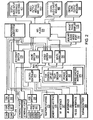
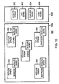
- Fig. 2 is a schematic block diagram showing a high-level hardware architecture of the programmable multimedia controller.
- the various components shown may be arranged on a "motherboard" of the controller, or on a plurality of cards interconnected by a backplane (not shown).
- a microcontroller 210 manages the general operation of the system.
- the microcontroller is a 32-bit model MCF5234 microcontroller available from Freescale Semiconductor Inc.
- the microcontroller 210 is coupled to an audio switch 215 and a video switch 220 via a bus 218.
- the audio switch 215 and the video switch 220 are preferably crosspoint switches capable of switching a number of connections simultaneously. However many other types of switches capable of switching digital signals may be employed, for example Time Division Multiplexing (TDM) switches or other devices.
- TDM Time Division Multiplexing
- a mid plane 235 interconnects the switches to a variety of input and output modules such as, for example, Digital Video Input Modules with HDMI 600, Video Output Modules with HDMI 1000, Digital Audio Input Modules 400, and Digital Audio Output Modules 900.
- the mid plane 235 is further coupled to an Ethernet switch 230 that permits switching of 10BaseT, 100BaseT or Gigabyte Ethernet signals.
- the Ethernet switch 230 interconnects Ethernet ports 232 and a processing subsystem 240 to the microcontroller 210.
- the processing subsystem 240 includes a plurality of small form factor general purpose personal computers that provide redundant operation and/or load balancing.
- the processing subsystem 240 may include one or more storage devices, external to the personal computers, to provide expanded storage capacity, for example, to store digital media.
- USB Universal Serial Bus
- a memory card interface 225 may also be connected to the USB hub 243.
- the interface accepts one or more well-known memory card formats, for example CompactFlashTM cards, Memory StickTM cards, Secure DigitalTM (SD) cards, or other formats.
- a USB switch 244 is employed to switch USB links among the multiple processing components that may be present in the processing subsystem 240.
- IEEE 1394 also known as FireWire®
- FireWire® IEEE 1394
- the microcontroller 210 is further connected to a Serial Peripheral Interface (SPI) and Inter-Integrated Circuit (I 2 C) distribution circuit 250, which provides a serial communication interface to relatively low data transfer rate devices.
- SPI Serial Peripheral Interface
- I 2 C Inter-Integrated Circuit
- the SPI/ I 2 C controller 250 is connected to the mid-plane connector 235 and thereby provides control commands from the microcontroller 210 to the modules and other devices in the PMC 100. Further connections from SPI/ I 2 C controller 250 are provided to devices such as a fan controller 251, a temperature sensor 252 and a power manager circuit 253, which manage the thermal characteristics of the system and prevent overheating.
- the microcontroller 210 is also connected to Infra-Red (IR) interface 260, an RS232 interface 265, and an RF interface 267, that permit interconnection with external devices. Such interaction permits PMC 100 to control external devices.
- the interfaces may receive control signals that control the operation of the programmable multimedia controller itself. It is expressly contemplated that various other interfaces, including WI-FI, BluetoothTM, ZigBeeTM and other wired and wireless interfaces, may be used with the multimedia controller 100.
- an Auxiliary Audio/Video Port 700 is provided for interconnecting one or more video game systems, camcorders, computers, karaoke machines, or other devices.
- a telephone interface 270 is provided for connecting to the public switch telephone network or to a private network, and to connect to one or more telephone handsets.
- a device control interface 275 is provided to communicate with lighting, home automation, and motor and/or relay operated devices.
- An expansion port 280 is provided for linking several programmable multimedia controllers together to form an expanded system.
- a front panel display 1150 permits presentation of status, configuration, and/or other information to a user.
- the front panel display may accept video data originating from any input source connected to the system, such that a user may preview video content on the front panel display 1150.
- the front panel display 1150 may be implemented with a touch sensitive display and used as described below.
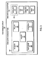
- Fig. 3 is an illustrative embodiment of a screen for touch sensitive display such as display 300 ( Fig. 1 ) or front panel display 1150 ( Fig. 2 ).
- Fig. 3 shows two groups of touch sensitive buttons.
- the first group of buttons shall be referred to collectively as video output display device buttons 301.
- Each of video output display device buttons 301 corresponds with or represents a video output display device which is interconnected with PMC 100 ( Figs. 1 and 2 ).
- PMC 100 is illustratively interconnected with televisions in a bedroom, kitchen, garage, boathouse, and living room, corresponding to touch sensitive buttons 302, 304, 306, 308, and 310, respectively. It should be understood that other types and any number of video output display devices could be interconnected with PMC 100 in a particular application.
- a second group of buttons is referred to collectively as video input device buttons 303.
- Each video input device button 303 corresponds with or represents a video input device interconnected with PMC 100.
- PMC 100 is interconnected with a satellite TV receiver, a DVD player, a computer and a cable TV box corresponding to buttons 305, 307, 309 and 311, respectively.
- a given source type for example, three cable boxes
- they are represented as a single video input device button.
- a "drawer” slides out on the display, illustratively at the bottom of the screen. This drawer or panel shows each of the three sources individually.
- the single video input device button is functioning as a source type button.
- any video output display device or video input device represented by a button on display 300 may be chosen (selected) by a user simply touching the appropriate button.
- This is illustratively represented by dotted line 312 which is intended to indicate that the user has selected the satellite TV receiver as a desired video input device.
- a desired video signal source e.g., channel
- Various available channels such as ESPN, TNT, HGTV, ABC, etc., are represented by touch sensitive buttons on touch sensitive display 402.
- the user may choose a desired video signal source simply by touching its associated button.
- HGTV has been chosen by a user and is denoted chosen video signal source button 401.
- any of touch sensitive buttons shown in display 400 may display a live stream of the video signal source it represents.
- the button denoted "ESPN Stream” may display the live ESPN video signal, thus enabling the user to see what content is currently playing before making a selection.
- the button can also be arranged to play sound from a selected audio-only channel.
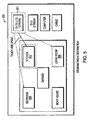
- a user would typically wish to display the chosen video signal on a television or other device. This may be done by establishing a communication path through PMC 100, via video switch 220 ( Fig. 2 ), between the video input device and one or more video output display devices.
- a user has established a connection between a video input device (i.e., satellite TV receiver 501) and each of three video output display devices (i.e., kitchen TV 502, bedroom TV 503, and living room TV 504).
- a desired video output display device selects a desire video input source and drags and drops the corresponding button onto the previously selected video output display device button.
- the video output display device button is altered in appearance. For example, if the user drags satellite TV receiver button 501 and drops it onto kitchen TV button 502, then the appearance of kitchen TV button 502 will change and display the video stream/signal of whatever video signal source the user previously selected in display screen 400.
- a small tag 601 overlays one corner of each video output display device button once a connection is established between the corresponding video output display device and a video input source.
- Tag 601 provides a visual indicator for the user as to which video input device is currently connected to a particular output device.
- connections have been established between a satellite TV receiver and each of the televisions located in bedroom 602, kitchen 603, and living room 604.
- the corresponding video output display device buttons appear empty as indicated by buttons 605 and 606.
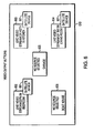
- Fig. 7 is flowchart showing the steps for a user to select a desired video signal source and establish a connection between a desired video input device and a desired video output display device.
- a user presses a touch sensitive button which corresponds to a video input device on which a user wishes to designate to a video output display device (step 701) on the touch sensitive display 300 ( Fig. 1 ).
- the PMC 100 may cause the display 300 to display all of the available video signal sources for that particular video input device (step 702).
- the user can then choose a desired video signal by pressing a touch sensitive button associated with a desired video signal source (step 703).
- the user drags a touch sensitive button associated with the chosen source and drops it on one or more desired video signal output device buttons.
- PMC 100 will respond by establishing appropriate connections through its video switch.
- a live video signal begins to stream onto the output device button (step 705).
- a small tag is added to the connected output device button that serves as a visual indicator which video signal source is currently connected to the video output display device. (step 706).
- Figs. 8 and 9 show an illustrative touch sensitive display 800 that includes a first portion 800a that displays the group of video output display devices, such as the television-n in the bedroom 802, the kitchen 803, the garage 801, the boat house 805 and the living room 806.
- the second portion 800b of the display screen 800 illustrates the group of video input devices including the satellite stream 810, the DVD device 812, the computer 814 and the cable device 816.
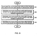
- Fig. 9 illustrates the method in which the user is able to broadcast the same video signal source to multiple video output display devices. Initially, the user selects the video output display devices to which the user wishes to broadcast (step 901).
- Video output display device 802 i.e., the bedroom TV
- Video output display devices 801 and 803 currently have no video input devices connected to them.
- Video output display device button 806 continues to operate with no change because it was not selected to be apart of the broadcast by the user in step 901.
- the group of video output display device buttons 1001-1006 are shown in the first portion 1002a of the display 1002 and the group of video input sources 1010 through 1016 are shown in second portion 1002b.
- the PMC is now streaming HGTV content from the video signal source, which is the satellite 1010, and the buttons for each television on which the content from that video input source 1010 is streaming are tagged with the satellite video input device tag button 1004.
- Fig. 11 is a flowchart showing a method for swapping a video input device or video signal source between two or more video output display devices.
- step 1101 the user touches the touch sensitive tag button on a selected video output display device.
- step 1102 the user drags the tag on the output device the user wishes to swap video input devices with (step 1102) and drops the tag button on the video output display device button which is the target of the swap (step 1 103).
- step 1102 the user touches the touch sensitive tag button on a selected video output display device.
- the user drags the tag on the output device the user wishes to swap video input devices with (step 1102) and drops the tag button on the video output display device button which is the target of the swap (step 1 103).
- step 1102 the user touches the touch sensitive tag button on a selected video output display device.
- step 1102 the user drags the tag on the output device the user wishes to swap video input devices with
- step 1 103 the tag button on the video output display device button which is the target of the swap
Landscapes
- Engineering & Computer Science (AREA)
- Multimedia (AREA)
- Signal Processing (AREA)
- General Engineering & Computer Science (AREA)
- Theoretical Computer Science (AREA)
- Human Computer Interaction (AREA)
- Physics & Mathematics (AREA)
- General Physics & Mathematics (AREA)
- Databases & Information Systems (AREA)
- Software Systems (AREA)
- Business, Economics & Management (AREA)
- Marketing (AREA)
- Two-Way Televisions, Distribution Of Moving Picture Or The Like (AREA)
- Details Of Television Systems (AREA)
- User Interface Of Digital Computer (AREA)
- Selective Calling Equipment (AREA)
Description
- Field of the Invention The present invention relates generally to a touch sensitive display which, when interconnected with a programmable multimedia controller, may be used to selectively connect one or more video signal sources to one or more video display devices.
-
US 2007/0143801 A1 describes a system and method for a programmable multimedia controller having a front panel display which provides for a single video display and button functionality for configuration and control. - The Article "Content oriented visual interface using video icons for visual database systems" by Tonomura et al published in the Journal of Visual Languages and Computing on January 1, 1999, pages 183-198 provides a content oriented visual interface using video icons for a visual database system.
-
US 2003/103088 A1 describes a user interface for a remote control that communicates with various items and components. -
US-A-5,745,710 describes a touch sensitive component for selecting a movie from a display screen. -
US-A-5,767,897 describes a video conference system involving remote sites. -
US 2008/0196068 A1 describes a portable device that functions as a remote control for controlling a TV display. - A touch sensitive display, which is interconnected with a programmable multimedia controller, enables a user to selectively connect a desired video input device with one or more video output display devices. Touch sensitive "buttons" or areas, each of which may represent or correspond to a video input device or a video output display device, are presented on the touch sensitive display. Available video input devices may include cable television, satellite television, DVD players, DVR, VCR gaming systems or other sources and components. Additionally, a video signal source such as cable television (Comcast ®), satellite (DirectTV ®), or digital television (local channels) offer a wide range of programming content on many channels such as CNN, ESPN and the like. The video input devices such as the satellite system and the DVD player, as well as the channels such as CNN and ESPN. IN addition, the programmable media controller is also coupled to audio-only devices, such as radio, satellite radio, CD player, digital audio players, personal media devices and the like. As used herein, vided input device also includes such audio only components. The video and audio devices, sources, channels, programming and content are sometimes collectively referred to herein as "media input." It should also be understood that the terms "video input" and "video input device" as used herein also encompasses audio input devices, and that the term "video signal source" encompasses audio signal sources.
- The user can also choose, as described further herein, which channel to send to a particular video output display device if one of the television video signal sources is selected for one of the video output display devices. Available video output display devices may include televisions, CRTs, touch panels, flat panel displays or others which are located throughout a home or a commercial establishment.
- In the illustrative system, the user may select a desired video input device to be connected, by way of a video switch located within the programmable multimedia controller, to a desired video output display device. To make such a selection, the user first touches a desired video output display device button, thus effectively selecting the video output display device associated with that button. Next, the user touches a desired video input device button. This gesture causes the video switch to create a communication path between the selected video input device and the selected video output display device. In addition, a "tag" appears on the video output display device button which provides a visual cue of what video input device is currently connected to the output device associated with that button.
- As noted, when the user selects a video input device, the user may also select a video signal source to apply to that video input device. Touch sensitive buttons which represent or correspond to video signal sources, such as broadcast, cable or satellite channels or other sources, are presented on the touch sensitive display. Video signal source buttons may display a live stream of what is playing on the corresponding video signal source. In this fashion, the user is able to see currently playing programs before deciding which video signal source to choose. Once a video signal source is chosen by the user, the video signal source may be streamed onto each button corresponding to each video output display device on which the chosen video signal is displayed. Thus, prior to changing any selections, the user is able to see what program is currently displayed on each of the video output display devices.
- The user may also "broadcast" a video signal source to multiple video output display devices. To do this, the user selects multiple video output display devices by touching the corresponding video output display device buttons. To broadcast a video signal from one video output device to all of the selected video output display devices, the user touches, drags and drops a video input device button onto one of the selected video output display device buttons. Additionally, the user may swap the video input devices (or video signal sources) connected to two different video output display devices.
- The invention may be better understood by referring to the following description in conjunction with the accompanying drawings in which like reference numerals indicate identical or functionally similar elements:
-
Fig. 1 is a block diagram of a programmable multimedia controller, interconnected to a number of devices including video input devices and video output display devices, according to an illustrative embodiment of the present invention. -
Fig. 2 is a schematic block diagram showing a high-level hardware architecture of the programmable multimedia controller ofFig. 1 ; -
Fig. 3 is a schematic block diagram of a touch sensitive display having touch sensitive buttons for several video output display devices and video input devices; -
Fig. 4 is a schematic block diagram of an exemplary illustrative embodiment of a touch sensitive display from which a user chooses a video signal source for a video input device; -
Fig. 5 is a detailed block diagram illustratively showing how a user designates a desired video input device for connection with a desired video output display device; -
Fig. 6 is a more detailed block diagram illustratively showing the appearance of video output display device buttons on a touch sensitive display once video input devices are chosen by a user; -
Fig. 7 is a flowchart showing a method for designating a destination for a video input device; -
Fig. 8 is a detailed block diagram illustratively showing how a user of a programmable multimedia controller can broadcast a video signal from one source to multiple video output display devices; -
Fig. 9 is a flowchart showing a method for broadcasting a video signal source; -
Fig. 10 is a detailed block diagram illustratively showing what the video input device buttons look like after a user has implemented a broadcast; and -
Fig. 11 is a flowchart showing a method for swapping a video input device or video signal source between two or more video output display devices. -
Fig. 1 is a block diagram of a programmable multimedia controller (PMC) 100, interconnected to a number of devices, according to an illustrative embodiment of the present invention. The term "programmable multimedia controller" should be interpreted broadly as a device capable of controlling, switching data between, or otherwise interoperating with, a variety of electronic devices, such as audio, video, telephony, data, security, motor-operated, relay-operated or other types of devices. By interacting with these devices, thePMC 100 may implement an integrated multimedia control solution. - In the illustrative embodiment, the
PMC 100 is connected to a wide range of audio/video components, for example, a compact disk (CD)player 105, a digital video disc (DVD)player 110, an audio/video receiver 115, atelevision 120,speakers 122, amicrophone 123, avideo camera 124 and apersonal media player 125. The programmable multimedia controller may also be connected to telephony devices such as atelephone network 130 andtelephone handsets 132. Thetelephone network 130 may be a publicly switched telephone network (PSTN), an Integrated Services Digital Network (ISDN) or other communications network. - In addition, the programmable multimedia controller may intercommunicate with variety of lighting and/or
home automation systems 135. These devices may operate via the X10 protocol developed by Pico Electronics, the INSTEON™ protocol developed by SmartHome, Inc, the CEBus standard managed by the CEBus Industry Council, RS232, or another well known automation or control protocol. Similarly,controller 100 may be connected to motor/relay operateddevices 137 that may include, for example, a heating, ventilation and air conditioning (HVAC) system, an irrigation system, an automatic shade or blind system, an electronic door lock, or other types of devices. - A computer network, such as the Internet 140, is connected to the
PMC 100. In addition, a personal computer (PC) 145,video game systems 150, home orstudio recording equipment 165 or other devices may also be connected. Further, one or moreremote control units 170 may be provided to manage the controller's functionality or to control devices connected to the controller. Suchremote control units 170 may be interconnected to the controller via a wired network connection or a wireless connection such as an infra-red link, a radio-frequency link, a Bluetooth™ link, a ZigBee™ link, WI-FI, or another appropriate data connection. - A touch
sensitive display 300 is also connected toPMC 100. As described in detail below, touchsensitive display 300 may be used by a user to directPMC 100 to establish communication paths between desired video input devices (e.g., DVD player 110) and desired video output display devices (e.g., television 120). -
Fig. 2 is a schematic block diagram showing a high-level hardware architecture of the programmable multimedia controller. The various components shown may be arranged on a "motherboard" of the controller, or on a plurality of cards interconnected by a backplane (not shown). Amicrocontroller 210 manages the general operation of the system. In the illustrative embodiment, the microcontroller is a 32-bit model MCF5234 microcontroller available from Freescale Semiconductor Inc. Themicrocontroller 210 is coupled to anaudio switch 215 and avideo switch 220 via abus 218. Theaudio switch 215 and thevideo switch 220 are preferably crosspoint switches capable of switching a number of connections simultaneously. However many other types of switches capable of switching digital signals may be employed, for example Time Division Multiplexing (TDM) switches or other devices. - A
mid plane 235 interconnects the switches to a variety of input and output modules such as, for example, Digital Video Input Modules withHDMI 600, Video Output Modules withHDMI 1000, DigitalAudio Input Modules 400, and DigitalAudio Output Modules 900. Themid plane 235 is further coupled to anEthernet switch 230 that permits switching of 10BaseT, 100BaseT or Gigabyte Ethernet signals. TheEthernet switch 230interconnects Ethernet ports 232 and aprocessing subsystem 240 to themicrocontroller 210. In one embodiment, theprocessing subsystem 240 includes a plurality of small form factor general purpose personal computers that provide redundant operation and/or load balancing. In some embodiments, theprocessing subsystem 240 may include one or more storage devices, external to the personal computers, to provide expanded storage capacity, for example, to store digital media. - Also, a number of Universal Serial Bus (USB)
ports 242 are interconnected to aUSB hub 243 for interconnection to theprocessing subsystem 240. Amemory card interface 225 may also be connected to theUSB hub 243. The interface accepts one or more well-known memory card formats, for example CompactFlash™ cards, Memory Stick™ cards, Secure Digital™ (SD) cards, or other formats. AUSB switch 244 is employed to switch USB links among the multiple processing components that may be present in theprocessing subsystem 240. In a similar manner, a number of IEEE 1394 (also known as FireWire®)ports 246 are interconnected to anIEEE 1394hub 247 and to anIEEE 1394switch 248. - The
microcontroller 210 is further connected to a Serial Peripheral Interface (SPI) and Inter-Integrated Circuit (I2C)distribution circuit 250, which provides a serial communication interface to relatively low data transfer rate devices. The SPI/ I2C controller 250 is connected to themid-plane connector 235 and thereby provides control commands from themicrocontroller 210 to the modules and other devices in thePMC 100. Further connections from SPI/ I2C controller 250 are provided to devices such as afan controller 251, atemperature sensor 252 and apower manager circuit 253, which manage the thermal characteristics of the system and prevent overheating. - The
microcontroller 210 is also connected to Infra-Red (IR)interface 260, anRS232 interface 265, and anRF interface 267, that permit interconnection with external devices. Suchinteraction permits PMC 100 to control external devices. In addition the interfaces may receive control signals that control the operation of the programmable multimedia controller itself. It is expressly contemplated that various other interfaces, including WI-FI, Bluetooth™, ZigBee™ and other wired and wireless interfaces, may be used with themultimedia controller 100. - In addition, an Auxiliary Audio/
Video Port 700 is provided for interconnecting one or more video game systems, camcorders, computers, karaoke machines, or other devices. Atelephone interface 270 is provided for connecting to the public switch telephone network or to a private network, and to connect to one or more telephone handsets. Further, adevice control interface 275 is provided to communicate with lighting, home automation, and motor and/or relay operated devices. Anexpansion port 280 is provided for linking several programmable multimedia controllers together to form an expanded system. - Finally, a
front panel display 1150 permits presentation of status, configuration, and/or other information to a user. In one embodiment the front panel display may accept video data originating from any input source connected to the system, such that a user may preview video content on thefront panel display 1150. In another embodiment, thefront panel display 1150 may be implemented with a touch sensitive display and used as described below. -
Fig. 3 is an illustrative embodiment of a screen for touch sensitive display such as display 300 (Fig. 1 ) or front panel display 1150 (Fig. 2 ).Fig. 3 shows two groups of touch sensitive buttons. By way of example, the first group of buttons shall be referred to collectively as video outputdisplay device buttons 301. Each of video outputdisplay device buttons 301 corresponds with or represents a video output display device which is interconnected with PMC 100 (Figs. 1 and2 ). For example, indisplay 300,PMC 100 is illustratively interconnected with televisions in a bedroom, kitchen, garage, boathouse, and living room, corresponding to touchsensitive buttons PMC 100 in a particular application. - A second group of buttons is referred to collectively as video
input device buttons 303. Each videoinput device button 303 corresponds with or represents a video input device interconnected withPMC 100. As shown,PMC 100 is interconnected with a satellite TV receiver, a DVD player, a computer and a cable TV box corresponding tobuttons - In general, any video output display device or video input device represented by a button on
display 300 may be chosen (selected) by a user simply touching the appropriate button. This is illustratively represented bydotted line 312 which is intended to indicate that the user has selected the satellite TV receiver as a desired video input device. - Having selected the satellite TV receiver by touching
button 305, the user may be presented with a screen, such as that shown inFig. 4 , from which the user may select a desired video signal source (e.g., channel). Various available channels such as ESPN, TNT, HGTV, ABC, etc., are represented by touch sensitive buttons on touchsensitive display 402. The user may choose a desired video signal source simply by touching its associated button. As shown, HGTV has been chosen by a user and is denoted chosen videosignal source button 401. - Advantageously, any of touch sensitive buttons shown in
display 400 may display a live stream of the video signal source it represents. For example, the button denoted "ESPN Stream" may display the live ESPN video signal, thus enabling the user to see what content is currently playing before making a selection. The button can also be arranged to play sound from a selected audio-only channel. - Having chosen a particular video input device and video signal source as described above, a user would typically wish to display the chosen video signal on a television or other device. This may be done by establishing a communication path through
PMC 100, via video switch 220 (Fig. 2 ), between the video input device and one or more video output display devices. Referring now toFig. 5 , a user has established a connection between a video input device (i.e., satellite TV receiver 501) and each of three video output display devices (i.e.,kitchen TV 502,bedroom TV 503, and living room TV 504). To establish the connections shown inFig. 5 , the user first selects a desired video output display device, then selects a desire video input source and drags and drops the corresponding button onto the previously selected video output display device button. - When the user drops a selected video input device button onto a video output display device button, the video output display device button is altered in appearance. For example, if the user drags satellite
TV receiver button 501 and drops it ontokitchen TV button 502, then the appearance ofkitchen TV button 502 will change and display the video stream/signal of whatever video signal source the user previously selected indisplay screen 400. - In addition, as may be seen best in
Fig. 6 , asmall tag 601 overlays one corner of each video output display device button once a connection is established between the corresponding video output display device and a video input source.Tag 601 provides a visual indicator for the user as to which video input device is currently connected to a particular output device. As shown inFig. 6 , connections have been established between a satellite TV receiver and each of the televisions located inbedroom 602,kitchen 603, andliving room 604. In the event that no connection has been established between a video input device and a video output display device, the corresponding video output display device buttons appear empty as indicated bybuttons -
Fig. 7 is flowchart showing the steps for a user to select a desired video signal source and establish a connection between a desired video input device and a desired video output display device. Initially, a user presses a touch sensitive button which corresponds to a video input device on which a user wishes to designate to a video output display device (step 701) on the touch sensitive display 300 (Fig. 1 ). Once a video input device is selected, thePMC 100 may cause thedisplay 300 to display all of the available video signal sources for that particular video input device (step 702). The user can then choose a desired video signal by pressing a touch sensitive button associated with a desired video signal source (step 703). Once the user selects a video signal source, the user then drags a touch sensitive button associated with the chosen source and drops it on one or more desired video signal output device buttons.PMC 100 will respond by establishing appropriate connections through its video switch. - In response to the user dropping the selected video input device button on a video output display device button, a live video signal begins to stream onto the output device button (step 705). Finally, a small tag is added to the connected output device button that serves as a visual indicator which video signal source is currently connected to the video output display device. (step 706).
-
Figs. 8 and9 show an illustrative touchsensitive display 800 that includes afirst portion 800a that displays the group of video output display devices, such as the television-n in thebedroom 802, thekitchen 803, thegarage 801, theboat house 805 and theliving room 806. Thesecond portion 800b of thedisplay screen 800 illustrates the group of video input devices including thesatellite stream 810, theDVD device 812, thecomputer 814 and thecable device 816.Fig. 9 illustrates the method in which the user is able to broadcast the same video signal source to multiple video output display devices. Initially, the user selects the video output display devices to which the user wishes to broadcast (step 901). For example, as shown inFig.8 , the user has selected video outputdisplay device buttons output display devices - Next, assume that the user wishes to broadcast the HGTV signal currently playing on
kitchen TV 805 ongarage TV 801 andboathouse TV 803. To do this, the user touches thetag button 804 and drags and drops it ontooutput device button 801. Because bothoutput device buttons Fig. 10 . Video outputdisplay device button 806 continues to operate with no change because it was not selected to be apart of the broadcast by the user instep 901. As shown inFig. 10 , the group of video output display device buttons 1001-1006 are shown in thefirst portion 1002a of thedisplay 1002 and the group ofvideo input sources 1010 through 1016 are shown insecond portion 1002b. In the example ofFig. 10 , the PMC is now streaming HGTV content from the video signal source, which is thesatellite 1010, and the buttons for each television on which the content from thatvideo input source 1010 is streaming are tagged with the satellite video inputdevice tag button 1004. - Finally the user may also swap video signal sources or video input devices.
Fig. 11 is a flowchart showing a method for swapping a video input device or video signal source between two or more video output display devices. First, instep 1101, the user touches the touch sensitive tag button on a selected video output display device. Then the user drags the tag on the output device the user wishes to swap video input devices with (step 1102) and drops the tag button on the video output display device button which is the target of the swap (step 1 103). Again, once the swap has been made, the video streaming on the affected video output display device buttons is altered to indicate to the user what is now being transmitted to that output device. - The foregoing description has been directed to particular embodiments of this invention. It will be apparent; that other variations and modifications may be made to the described embodiments, with the attainment of some or all of their advantages. Additionally, the procedures or processes may be implemented in hardware, software, embodied as a computer-readable medium having program instructions, firmware, or a combination thereof. Therefore, it is the object of the appended claims to cover all such variations and modifications as come within the scope of the invention.
Claims (16)
- An apparatus for controlling and selecting video input for one or more video output display devices, comprising:a plurality of video output display devices interconnected with a programmable multimedia controller;a plurality of video input devices interconnected with the programmable multimedia controller; anda touch sensitive display interconnected with the programmable multimedia controller, the touch sensitive display configured to receive a plurality of video signals from the video input devices and to display each of the signals in a touch sensitive video selection button, and to display a plurality of video input device buttons each corresponding to a video input device and a plurality of video output display device buttons each corresponding to a video output display device,wherein the programmable multimedia controller is programmed to, in response to a user dragging and dropping a selected video input device button onto a selected video output display device button, establish a communication path via a video switch to connect a selected video output display device and a selected video input device, and alter appearance of the selected video output display device button to display signals of the selected video input device and a tag that provides a visual indicator of which video input device is currently connected to the selected video output display device.
- A method for controlling and selecting video input for output on one or more video output display devices, comprising the steps:interconnecting a plurality of video output display devices with a programmable multimedia controller;interconnecting a plurality of video input devices with the programmable multimedia controller; andinterconnecting a touch sensitive display with the programmable multimedia controller, the display configured to receive video input from the plurality of video input devices and to display the signals generated by said video input devices in one or more touch sensitive video selection buttons on the touch sensitive display, and to display a plurality of video input device buttons each corresponding to a video input device and a plurality of video output display device buttons each corresponding to a video output display device,in response to a user dragging and dropping a selected video input device button onto a selected video output display device button, establish a communication path via a video switch to connect a selected video output display device and a selected video input device, and alter appearance of the selected video output display device button to display signals of the selected video input device and a tag that provides a visual indicator of which video input device is currently connected to the selected video output display device.
- The method for controlling and selecting media input for output on one or more video output display devices as defined in Claim 2, further comprising:streaming video content from the selected video input device to the touch sensitive display such that a user can view the programming currently being shown by the selected video input device in a small panel on the touch sensitive display .
- The method for controlling and selecting media input for output on one or more video output display devices as defined in Claim 3 further comprising:streaming a video signal from said selected video input device onto one or more video output display device buttons on said display.
- The method for controlling and selecting media input for output on one or more video output display devices as defined in Claim 2, further characterized in that:on said touch sensitive display, in response to a user selecting a plurality of touch sensitive video output display device buttons and dragging a video input tag to one of the video output display devices, said programmable multimedia controller commands said video switch to open a communication path to each of a plurality of selected video output display devices, anddisplaying video content represented by the video input tag on each of the selected video output display devices to thereby broadcast the video content on each of those selected video output display devices.
- The method for controlling and selecting media input for output on one or more video output display devices as defined in Claim 2, further comprising:swapping a video input source between two or more video output display devices;touching a touch sensitive video input tag on a selected video output display device button;dragging said tag onto a video output display device button which is a target of a swap;dropping the touch sensitive video input tag on the prospective video output display device button which the user wishes to swap; andtransmitting streaming video from the selected video input device to the video output display device that is the target of the swap.
- The method for controlling and selecting media input for output on one or more video output display devices as defined in Claim 2, wherein, in response to a user selecting a particular video input device, the programmable multimedia controller then commands the touch sensitive display to display streaming video in sections located on the touch sensitive display displaying programs then available from the selected video input device.
- The method for controlling and selecting media input for output on one or more video output display devices as defined in Claim 2, wherein a video output display device is one of a: TV, CRT, touch panel, flat panel display, computer monitor and personal media player.
- The method for controlling and selecting media input for output on one or more video output display devices as defined in Claim 2, wherein a video input device is one of a: cable television, satellite television, DVD player, DVR, VCR, computer, and video gaming system.
- The method for controlling and selecting media input for output on one or more video output display devices as defined in Claim 2, wherein a video input device is an audio input device including at least one of a: radio, satellite radio, CD player, personal media player and digital audio player.
- The apparatus for controlling and selecting media input for output on one or more video output display devices as defined in Claim 1 wherein said programmable multimedia controller is further programmed to display on the touch sensitive screen at or in close proximity to the selected video output display device button, streaming video to be directed to the selected video output display device.
- The apparatus for controlling and selecting media input for output on one or more video output display devices as defined in Claim 1 wherein said programmable multimedia controller is connected to the Internet.
- The apparatus for controlling and selecting media input for output on one or more video output display devices as defined in Claim 1 wherein said programmable multimedia controller includes a microcontroller programmed to manage the general operation of the system, and the video switch and audio switch are coupled to the microcontroller via a bus.
- The apparatus for controlling and selecting media input for output on one or more video output display devices as defined in Claim 1 wherein said video switch is a crosspoint switch that is capable of switching a number of connections simultaneously
- The apparatus for controlling and selecting media input for output on one or more video output display devices as defined in Claim 1 wherein said video switch is a time division multiplexing switch for switching digital signals.
- The apparatus for controlling and selecting media input for output on one or more video output display devices as defined in Claim 1 wherein said video output display devices are televisions in various locations in a house or commercial establishment.
Priority Applications (1)
| Application Number | Priority Date | Filing Date | Title |
|---|---|---|---|
| PL09739226T PL2291998T3 (en) | 2008-05-02 | 2009-05-01 | Touch sensitive video signal display for a programmable multimedia controller |
Applications Claiming Priority (2)
| Application Number | Priority Date | Filing Date | Title |
|---|---|---|---|
| US12631108P | 2008-05-02 | 2008-05-02 | |
| PCT/US2009/002690 WO2009134423A1 (en) | 2008-05-02 | 2009-05-01 | Touch sensitive video signal display for a programmable multimedia controller |
Publications (2)
| Publication Number | Publication Date |
|---|---|
| EP2291998A1 EP2291998A1 (en) | 2011-03-09 |
| EP2291998B1 true EP2291998B1 (en) | 2014-05-07 |
Family
ID=40825498
Family Applications (1)
| Application Number | Title | Priority Date | Filing Date |
|---|---|---|---|
| EP09739226.0A Active EP2291998B1 (en) | 2008-05-02 | 2009-05-01 | Touch sensitive video signal display for a programmable multimedia controller |
Country Status (15)
| Country | Link |
|---|---|
| US (1) | US8884886B2 (en) |
| EP (1) | EP2291998B1 (en) |
| JP (1) | JP5613151B2 (en) |
| KR (1) | KR101557176B1 (en) |
| CN (1) | CN102160368A (en) |
| AU (1) | AU2009241750B2 (en) |
| BR (1) | BRPI0911559B1 (en) |
| CA (1) | CA2722851C (en) |
| DK (1) | DK2291998T3 (en) |
| ES (1) | ES2470742T3 (en) |
| IL (1) | IL209064A (en) |
| MX (1) | MX2010011831A (en) |
| NZ (1) | NZ588888A (en) |
| PL (1) | PL2291998T3 (en) |
| WO (1) | WO2009134423A1 (en) |
Families Citing this family (39)
| Publication number | Priority date | Publication date | Assignee | Title |
|---|---|---|---|---|
| US20100162328A1 (en) * | 2008-12-24 | 2010-06-24 | Broadcom Corporation | Remote control device transaction setup in a home network |
| US10613704B2 (en) | 2009-06-03 | 2020-04-07 | Savant Systems, Llc | Small screen virtual room-based user interface |
| US10775960B2 (en) | 2009-06-03 | 2020-09-15 | Savant Systems, Inc. | User generated virtual room-based user interface |
| EP2438800B1 (en) * | 2009-06-03 | 2014-11-19 | Savant Systems LLC. | Virtual room-based light fixture and device control |
| US20110093132A1 (en) * | 2009-10-19 | 2011-04-21 | Apple Inc. | Platform-independent thermal management of components in electronic devices |
| CN101951507A (en) * | 2010-10-11 | 2011-01-19 | 大道计算机技术(上海)有限公司 | Large screen IP (Internet Protocol) video stream access equipment and implementation method thereof |
| KR101833454B1 (en) * | 2011-06-14 | 2018-04-13 | 삼성전자주식회사 | Method for local area wireless communication and mobile terminal therefor |
| KR101160681B1 (en) | 2011-10-19 | 2012-06-28 | 배경덕 | Method, mobile communication terminal and computer-readable recording medium for operating specific function when activaing of mobile communication terminal |
| KR101799408B1 (en) | 2011-11-03 | 2017-11-20 | 삼성전자주식회사 | Apparatus and method for controlling controllable device in portable terminal |
| KR102078093B1 (en) * | 2011-11-10 | 2020-02-18 | 삼성전자 주식회사 | Device and method for controlling temperature of wireless terminal |
| TW201349085A (en) * | 2012-05-22 | 2013-12-01 | Pegatron Corp | Method for managing multimedia files, digital media controller, multimedia file management system |
| US9521352B2 (en) | 2012-09-13 | 2016-12-13 | Naxos Finance Sa | Television set capable of identifying a plurality of peripherals and allowing to select and display the contents of one of the same |
| CN103021083B (en) * | 2012-12-19 | 2015-10-28 | 深圳怡化电脑股份有限公司 | The method that atm device is withdrawn the money by drag and drop figure and graphical interfaces |
| KR101960313B1 (en) * | 2012-12-31 | 2019-03-20 | 엘지전자 주식회사 | smart device, method of controlling a smart device |
| US20140258880A1 (en) * | 2013-03-07 | 2014-09-11 | Nokia Corporation | Method and apparatus for gesture-based interaction with devices and transferring of contents |
| CN103200462B (en) * | 2013-03-23 | 2015-12-02 | 四三九九网络股份有限公司 | A kind of video broadcasting method of swf file |
| CN106412655B (en) * | 2014-01-24 | 2019-12-03 | 青岛海信电器股份有限公司 | A touch TV and its control method and control device |
| JP6589858B2 (en) * | 2014-04-02 | 2019-10-16 | ソニー株式会社 | Connection control device and connection control method |
| GB2529295B (en) * | 2014-06-13 | 2018-02-28 | Harman Int Ind | Media system controllers |
| KR20160041243A (en) * | 2014-10-07 | 2016-04-18 | 삼성전자주식회사 | Display apparatus, display system, and method for display |
| CN113384359B (en) * | 2015-10-02 | 2024-08-20 | 索尼公司 | Medical control device, control method, program, and medical control system |
| US12276420B2 (en) | 2016-02-03 | 2025-04-15 | Strong Force Iot Portfolio 2016, Llc | Industrial internet of things smart heating systems and methods that produce and use hydrogen fuel |
| US11774944B2 (en) | 2016-05-09 | 2023-10-03 | Strong Force Iot Portfolio 2016, Llc | Methods and systems for the industrial internet of things |
| US11327475B2 (en) | 2016-05-09 | 2022-05-10 | Strong Force Iot Portfolio 2016, Llc | Methods and systems for intelligent collection and analysis of vehicle data |
| CN114625077B (en) | 2016-05-09 | 2024-12-17 | 强力物联网投资组合2016有限公司 | Method and system for industrial Internet of things |
| US10754334B2 (en) | 2016-05-09 | 2020-08-25 | Strong Force Iot Portfolio 2016, Llc | Methods and systems for industrial internet of things data collection for process adjustment in an upstream oil and gas environment |
| US10983507B2 (en) | 2016-05-09 | 2021-04-20 | Strong Force Iot Portfolio 2016, Llc | Method for data collection and frequency analysis with self-organization functionality |
| US11237546B2 (en) | 2016-06-15 | 2022-02-01 | Strong Force loT Portfolio 2016, LLC | Method and system of modifying a data collection trajectory for vehicles |
| US11442445B2 (en) | 2017-08-02 | 2022-09-13 | Strong Force Iot Portfolio 2016, Llc | Data collection systems and methods with alternate routing of input channels |
| CN209085657U (en) | 2017-08-02 | 2019-07-09 | 强力物联网投资组合2016有限公司 | For data gathering system related or industrial environment with chemical production technology |
| CN108260011B (en) * | 2018-01-24 | 2024-01-12 | 堃昊电子科技(江苏)有限公司 | Method and system for realizing painting on display equipment |
| KR102026709B1 (en) * | 2018-02-22 | 2019-09-30 | 삼성전자 주식회사 | Method for local area wireless communication and mobile terminal therefor |
| US20200133254A1 (en) | 2018-05-07 | 2020-04-30 | Strong Force Iot Portfolio 2016, Llc | Methods and systems for data collection, learning, and streaming of machine signals for part identification and operating characteristics determination using the industrial internet of things |
| JP7549843B2 (en) | 2019-01-13 | 2024-09-12 | ストロング フォース アイオーティ ポートフォリオ 2016,エルエルシー | Method, system, kit, and apparatus for monitoring and managing an industrial environment |
| CN110162288A (en) * | 2019-06-03 | 2019-08-23 | 北京淳中科技股份有限公司 | A kind of method, apparatus, equipment and the medium of determining display area |
| US11688140B2 (en) | 2019-09-11 | 2023-06-27 | Savant Systems, Inc. | Three dimensional virtual room-based user interface for a home automation system |
| KR102056124B1 (en) | 2019-09-16 | 2019-12-16 | 삼성전자 주식회사 | Method for local area wireless communication and mobile terminal therefor |
| US11356735B2 (en) * | 2019-10-15 | 2022-06-07 | Sling Media Pvt Ltd. | Devices, systems and processes for multi-device access, control and presentation of streaming content |
| CN113038052B (en) * | 2021-03-29 | 2022-08-16 | 浙江大华技术股份有限公司 | Digital video recorder, control method thereof, device storage medium and electronic device |
Family Cites Families (24)
| Publication number | Priority date | Publication date | Assignee | Title |
|---|---|---|---|---|
| US5524195A (en) * | 1993-05-24 | 1996-06-04 | Sun Microsystems, Inc. | Graphical user interface for interactive television with an animated agent |
| US5790946A (en) * | 1993-07-15 | 1998-08-04 | Rotzoll; Robert R. | Wake up device for a communications system |
| JPH0879847A (en) * | 1994-09-05 | 1996-03-22 | Hitachi Ltd | Information system, AV equipment and remote control operating device constituting the system |
| US5767897A (en) * | 1994-10-31 | 1998-06-16 | Picturetel Corporation | Video conferencing system |
| DE69632384T2 (en) * | 1995-12-19 | 2005-05-04 | Canon K.K. | Apparatus and method for controlling a plurality of remote cameras |
| JP3600865B2 (en) | 1996-09-20 | 2004-12-15 | 株式会社ニコン | Image playback device |
| US7831930B2 (en) * | 2001-11-20 | 2010-11-09 | Universal Electronics Inc. | System and method for displaying a user interface for a remote control application |
| US8098140B1 (en) * | 2000-07-13 | 2012-01-17 | Universal Electronics Inc. | Customizable and upgradable devices and methods related thereto |
| US6437836B1 (en) * | 1998-09-21 | 2002-08-20 | Navispace, Inc. | Extended functionally remote control system and method therefore |
| JP4235300B2 (en) * | 1999-01-14 | 2009-03-11 | キヤノン株式会社 | Communications system |
| JP2001092575A (en) * | 1999-09-20 | 2001-04-06 | Nec Corp | System and method for visually controlling connection of equipment |
| JP3955773B2 (en) * | 2002-03-06 | 2007-08-08 | パナソニック コミュニケーションズ株式会社 | Multifunction machine and control method thereof |
| US20050024488A1 (en) * | 2002-12-20 | 2005-02-03 | Borg Andrew S. | Distributed immersive entertainment system |
| US7266777B2 (en) * | 2004-09-08 | 2007-09-04 | Universal Electronics Inc. | Configurable controlling device having an associated editing program |
| US8745132B2 (en) * | 2004-09-10 | 2014-06-03 | Silver State Intellectual Technologies, Inc. | System and method for audio and video portable publishing system |
| US7461343B2 (en) * | 2004-11-08 | 2008-12-02 | Lawrence Kates | Touch-screen remote control for multimedia equipment |
| EP2632152B1 (en) * | 2005-03-02 | 2017-06-14 | Rovi Guides, Inc. | Playlists and bookmarks in an interactive media guidance application system |
| US9153125B2 (en) | 2005-12-20 | 2015-10-06 | Savant Systems, Llc | Programmable multimedia controller with programmable services |
| US20070143801A1 (en) * | 2005-12-20 | 2007-06-21 | Madonna Robert P | System and method for a programmable multimedia controller |
| US8054294B2 (en) * | 2006-03-31 | 2011-11-08 | Sony Corporation | Touch screen remote control system for use in controlling one or more devices |
| US8421602B2 (en) * | 2006-09-13 | 2013-04-16 | Savant Systems, Llc | Remote control unit for a programmable multimedia controller |
| TW200835320A (en) * | 2007-02-09 | 2008-08-16 | Mitac Int Corp | Portable multimedia device |
| US20090240502A1 (en) * | 2008-03-24 | 2009-09-24 | Sony Corporation | Multimedia controller tablet |
| US20120194442A1 (en) * | 2011-01-31 | 2012-08-02 | Robin Sheeley | Touch screen video source control system |
-
2009
- 2009-05-01 CA CA2722851A patent/CA2722851C/en active Active
- 2009-05-01 EP EP09739226.0A patent/EP2291998B1/en active Active
- 2009-05-01 MX MX2010011831A patent/MX2010011831A/en active IP Right Grant
- 2009-05-01 DK DK09739226.0T patent/DK2291998T3/en active
- 2009-05-01 ES ES09739226.0T patent/ES2470742T3/en active Active
- 2009-05-01 WO PCT/US2009/002690 patent/WO2009134423A1/en not_active Ceased
- 2009-05-01 CN CN2009801259449A patent/CN102160368A/en active Pending
- 2009-05-01 KR KR1020107027142A patent/KR101557176B1/en active Active
- 2009-05-01 JP JP2011507462A patent/JP5613151B2/en active Active
- 2009-05-01 NZ NZ588888A patent/NZ588888A/en unknown
- 2009-05-01 AU AU2009241750A patent/AU2009241750B2/en active Active
- 2009-05-01 BR BRPI0911559-5A patent/BRPI0911559B1/en active IP Right Grant
- 2009-05-01 US US12/434,189 patent/US8884886B2/en active Active
- 2009-05-01 PL PL09739226T patent/PL2291998T3/en unknown
-
2010
- 2010-11-01 IL IL209064A patent/IL209064A/en active IP Right Grant
Also Published As
| Publication number | Publication date |
|---|---|
| JP5613151B2 (en) | 2014-10-22 |
| EP2291998A1 (en) | 2011-03-09 |
| JP2011524105A (en) | 2011-08-25 |
| BRPI0911559B1 (en) | 2021-01-05 |
| CA2722851A1 (en) | 2009-11-05 |
| US20090303197A1 (en) | 2009-12-10 |
| AU2009241750B2 (en) | 2013-07-11 |
| BRPI0911559A2 (en) | 2017-06-20 |
| MX2010011831A (en) | 2010-11-30 |
| IL209064A0 (en) | 2011-01-31 |
| CA2722851C (en) | 2017-07-18 |
| NZ588888A (en) | 2012-10-26 |
| AU2009241750A1 (en) | 2009-11-05 |
| DK2291998T3 (en) | 2014-08-11 |
| PL2291998T3 (en) | 2014-09-30 |
| KR20110021841A (en) | 2011-03-04 |
| CN102160368A (en) | 2011-08-17 |
| IL209064A (en) | 2015-01-29 |
| KR101557176B1 (en) | 2015-10-02 |
| WO2009134423A1 (en) | 2009-11-05 |
| ES2470742T3 (en) | 2014-06-24 |
| US8884886B2 (en) | 2014-11-11 |
Similar Documents
| Publication | Publication Date | Title |
|---|---|---|
| EP2291998B1 (en) | Touch sensitive video signal display for a programmable multimedia controller | |
| US9153125B2 (en) | Programmable multimedia controller with programmable services | |
| JP5557798B2 (en) | User interface for multi-device control | |
| US6961099B2 (en) | Method and apparatus for automatically switching between analog and digital input signals | |
| KR101248703B1 (en) | Method, system, and computer-readable recording medium for setup of multi-device control | |
| US7234115B1 (en) | Home entertainment system and method | |
| US20070298656A1 (en) | Switch apparatus for multiple high definition multimedia interface sources |
Legal Events
| Date | Code | Title | Description |
|---|---|---|---|
| PUAI | Public reference made under article 153(3) epc to a published international application that has entered the european phase |
Free format text: ORIGINAL CODE: 0009012 |
|
| 17P | Request for examination filed |
Effective date: 20101201 |
|
| AK | Designated contracting states |
Kind code of ref document: A1 Designated state(s): AT BE BG CH CY CZ DE DK EE ES FI FR GB GR HR HU IE IS IT LI LT LU LV MC MK MT NL NO PL PT RO SE SI SK TR |
|
| AX | Request for extension of the european patent |
Extension state: AL BA RS |
|
| RIN1 | Information on inventor provided before grant (corrected) |
Inventor name: BONCZEK, BRYAN, S.C/O SAVANT SYSTEMS, LLC Inventor name: MADONNA, ROBERT, P. Inventor name: SILVA, MICHAEL, C. |
|
| DAX | Request for extension of the european patent (deleted) | ||
| 17Q | First examination report despatched |
Effective date: 20120518 |
|
| 17Q | First examination report despatched |
Effective date: 20120601 |
|
| GRAP | Despatch of communication of intention to grant a patent |
Free format text: ORIGINAL CODE: EPIDOSNIGR1 |
|
| RIC1 | Information provided on ipc code assigned before grant |
Ipc: H04N 5/44 20110101ALI20131022BHEP Ipc: H04N 21/44 20110101ALI20131022BHEP Ipc: H04N 5/765 20060101ALI20131022BHEP Ipc: H04N 21/472 20110101ALI20131022BHEP Ipc: H04N 5/00 20110101AFI20131022BHEP Ipc: H04N 21/41 20110101ALI20131022BHEP Ipc: G06F 3/0486 20130101ALI20131022BHEP Ipc: H04N 21/431 20110101ALI20131022BHEP Ipc: H04N 21/436 20110101ALI20131022BHEP Ipc: H04N 5/445 20110101ALI20131022BHEP Ipc: H04N 21/443 20110101ALI20131022BHEP Ipc: G06F 3/0488 20130101ALI20131022BHEP |
|
| INTG | Intention to grant announced |
Effective date: 20131127 |
|
| GRAS | Grant fee paid |
Free format text: ORIGINAL CODE: EPIDOSNIGR3 |
|
| GRAP | Despatch of communication of intention to grant a patent |
Free format text: ORIGINAL CODE: EPIDOSNIGR1 |
|
| GRAA | (expected) grant |
Free format text: ORIGINAL CODE: 0009210 |
|
| INTG | Intention to grant announced |
Effective date: 20140318 |
|
| AK | Designated contracting states |
Kind code of ref document: B1 Designated state(s): AT BE BG CH CY CZ DE DK EE ES FI FR GB GR HR HU IE IS IT LI LT LU LV MC MK MT NL NO PL PT RO SE SI SK TR |
|
| REG | Reference to a national code |
Ref country code: GB Ref legal event code: FG4D |
|
| REG | Reference to a national code |
Ref country code: AT Ref legal event code: REF Ref document number: 667442 Country of ref document: AT Kind code of ref document: T Effective date: 20140515 |
|
| REG | Reference to a national code |
Ref country code: CH Ref legal event code: NV Representative=s name: FIAMMENGHI-FIAMMENGHI, CH |
|
| REG | Reference to a national code |
Ref country code: IE Ref legal event code: FG4D |
|
| REG | Reference to a national code |
Ref country code: DE Ref legal event code: R096 Ref document number: 602009023917 Country of ref document: DE Effective date: 20140618 |
|
| REG | Reference to a national code |
Ref country code: ES Ref legal event code: FG2A Ref document number: 2470742 Country of ref document: ES Kind code of ref document: T3 Effective date: 20140624 |
|
| REG | Reference to a national code |
Ref country code: NL Ref legal event code: T3 |
|
| REG | Reference to a national code |
Ref country code: DK Ref legal event code: T3 Effective date: 20140807 |
|
| REG | Reference to a national code |
Ref country code: PL Ref legal event code: T3 |
|
| REG | Reference to a national code |
Ref country code: LT Ref legal event code: MG4D |
|
| PG25 | Lapsed in a contracting state [announced via postgrant information from national office to epo] |
Ref country code: GR Free format text: LAPSE BECAUSE OF FAILURE TO SUBMIT A TRANSLATION OF THE DESCRIPTION OR TO PAY THE FEE WITHIN THE PRESCRIBED TIME-LIMIT Effective date: 20140808 Ref country code: CY Free format text: LAPSE BECAUSE OF FAILURE TO SUBMIT A TRANSLATION OF THE DESCRIPTION OR TO PAY THE FEE WITHIN THE PRESCRIBED TIME-LIMIT Effective date: 20140507 Ref country code: NO Free format text: LAPSE BECAUSE OF FAILURE TO SUBMIT A TRANSLATION OF THE DESCRIPTION OR TO PAY THE FEE WITHIN THE PRESCRIBED TIME-LIMIT Effective date: 20140807 Ref country code: IS Free format text: LAPSE BECAUSE OF FAILURE TO SUBMIT A TRANSLATION OF THE DESCRIPTION OR TO PAY THE FEE WITHIN THE PRESCRIBED TIME-LIMIT Effective date: 20140907 Ref country code: LT Free format text: LAPSE BECAUSE OF FAILURE TO SUBMIT A TRANSLATION OF THE DESCRIPTION OR TO PAY THE FEE WITHIN THE PRESCRIBED TIME-LIMIT Effective date: 20140507 |
|
| PG25 | Lapsed in a contracting state [announced via postgrant information from national office to epo] |
Ref country code: SE Free format text: LAPSE BECAUSE OF FAILURE TO SUBMIT A TRANSLATION OF THE DESCRIPTION OR TO PAY THE FEE WITHIN THE PRESCRIBED TIME-LIMIT Effective date: 20140507 Ref country code: LV Free format text: LAPSE BECAUSE OF FAILURE TO SUBMIT A TRANSLATION OF THE DESCRIPTION OR TO PAY THE FEE WITHIN THE PRESCRIBED TIME-LIMIT Effective date: 20140507 Ref country code: HR Free format text: LAPSE BECAUSE OF FAILURE TO SUBMIT A TRANSLATION OF THE DESCRIPTION OR TO PAY THE FEE WITHIN THE PRESCRIBED TIME-LIMIT Effective date: 20140507 |
|
| PG25 | Lapsed in a contracting state [announced via postgrant information from national office to epo] |
Ref country code: PT Free format text: LAPSE BECAUSE OF FAILURE TO SUBMIT A TRANSLATION OF THE DESCRIPTION OR TO PAY THE FEE WITHIN THE PRESCRIBED TIME-LIMIT Effective date: 20140908 |
|
| PG25 | Lapsed in a contracting state [announced via postgrant information from national office to epo] |
Ref country code: SK Free format text: LAPSE BECAUSE OF FAILURE TO SUBMIT A TRANSLATION OF THE DESCRIPTION OR TO PAY THE FEE WITHIN THE PRESCRIBED TIME-LIMIT Effective date: 20140507 Ref country code: RO Free format text: LAPSE BECAUSE OF FAILURE TO SUBMIT A TRANSLATION OF THE DESCRIPTION OR TO PAY THE FEE WITHIN THE PRESCRIBED TIME-LIMIT Effective date: 20140507 Ref country code: EE Free format text: LAPSE BECAUSE OF FAILURE TO SUBMIT A TRANSLATION OF THE DESCRIPTION OR TO PAY THE FEE WITHIN THE PRESCRIBED TIME-LIMIT Effective date: 20140507 |
|
| REG | Reference to a national code |
Ref country code: DE Ref legal event code: R097 Ref document number: 602009023917 Country of ref document: DE |
|
| PLBE | No opposition filed within time limit |
Free format text: ORIGINAL CODE: 0009261 |
|
| STAA | Information on the status of an ep patent application or granted ep patent |
Free format text: STATUS: NO OPPOSITION FILED WITHIN TIME LIMIT |
|
| 26N | No opposition filed |
Effective date: 20150210 |
|
| REG | Reference to a national code |
Ref country code: DE Ref legal event code: R097 Ref document number: 602009023917 Country of ref document: DE Effective date: 20150210 |
|
| PG25 | Lapsed in a contracting state [announced via postgrant information from national office to epo] |
Ref country code: SI Free format text: LAPSE BECAUSE OF FAILURE TO SUBMIT A TRANSLATION OF THE DESCRIPTION OR TO PAY THE FEE WITHIN THE PRESCRIBED TIME-LIMIT Effective date: 20140507 |
|
| PG25 | Lapsed in a contracting state [announced via postgrant information from national office to epo] |
Ref country code: LU Free format text: LAPSE BECAUSE OF FAILURE TO SUBMIT A TRANSLATION OF THE DESCRIPTION OR TO PAY THE FEE WITHIN THE PRESCRIBED TIME-LIMIT Effective date: 20150501 Ref country code: MC Free format text: LAPSE BECAUSE OF FAILURE TO SUBMIT A TRANSLATION OF THE DESCRIPTION OR TO PAY THE FEE WITHIN THE PRESCRIBED TIME-LIMIT Effective date: 20140507 |
|
| REG | Reference to a national code |
Ref country code: FR Ref legal event code: PLFP Year of fee payment: 8 |
|
| PG25 | Lapsed in a contracting state [announced via postgrant information from national office to epo] |
Ref country code: MT Free format text: LAPSE BECAUSE OF FAILURE TO SUBMIT A TRANSLATION OF THE DESCRIPTION OR TO PAY THE FEE WITHIN THE PRESCRIBED TIME-LIMIT Effective date: 20140507 |
|
| REG | Reference to a national code |
Ref country code: FR Ref legal event code: PLFP Year of fee payment: 9 |
|
| PG25 | Lapsed in a contracting state [announced via postgrant information from national office to epo] |
Ref country code: HU Free format text: LAPSE BECAUSE OF FAILURE TO SUBMIT A TRANSLATION OF THE DESCRIPTION OR TO PAY THE FEE WITHIN THE PRESCRIBED TIME-LIMIT; INVALID AB INITIO Effective date: 20090501 |
|
| PG25 | Lapsed in a contracting state [announced via postgrant information from national office to epo] |
Ref country code: BG Free format text: THE PATENT HAS BEEN ANNULLED BY A DECISION OF A NATIONAL AUTHORITY Effective date: 20150531 |
|
| REG | Reference to a national code |
Ref country code: FR Ref legal event code: PLFP Year of fee payment: 10 |
|
| PG25 | Lapsed in a contracting state [announced via postgrant information from national office to epo] |
Ref country code: MK Free format text: LAPSE BECAUSE OF FAILURE TO SUBMIT A TRANSLATION OF THE DESCRIPTION OR TO PAY THE FEE WITHIN THE PRESCRIBED TIME-LIMIT Effective date: 20140507 |
|
| REG | Reference to a national code |
Ref country code: DE Ref legal event code: R082 Ref document number: 602009023917 Country of ref document: DE Representative=s name: MEISSNER BOLTE PATENTANWAELTE RECHTSANWAELTE P, DE Ref country code: DE Ref legal event code: R081 Ref document number: 602009023917 Country of ref document: DE Owner name: SAVANT SYSTEMS, INC., HYANNIS, US Free format text: FORMER OWNER: SAVANT SYSTEMS LLC, OSTERVILLE, MASS., US |
|
| REG | Reference to a national code |
Ref country code: FI Ref legal event code: PCE Owner name: SAVANT SYSTEMS, INC. |
|
| REG | Reference to a national code |
Ref country code: CH Ref legal event code: PFUS Owner name: SAVANT SYSTEMS, INC., US Free format text: FORMER OWNER: SAVANT SYSTEMS LLC., US |
|
| REG | Reference to a national code |
Ref country code: NL Ref legal event code: PD Owner name: SAVANT SYSTEMS, INC.; US Free format text: DETAILS ASSIGNMENT: CHANGE OF OWNER(S), MERGE; FORMER OWNER NAME: SAVANT SYSTEMS LLC. Effective date: 20210225 |
|
| REG | Reference to a national code |
Ref country code: GB Ref legal event code: 732E Free format text: REGISTERED BETWEEN 20210429 AND 20210505 |
|
| REG | Reference to a national code |
Ref country code: BE Ref legal event code: PD Owner name: SAVANT SYSTEMS, INC.; US Free format text: DETAILS ASSIGNMENT: CHANGE OF OWNER(S), MERGE; FORMER OWNER NAME: SAVANT SYSTEMS LLC. Effective date: 20210511 |
|
| REG | Reference to a national code |
Ref country code: AT Ref legal event code: PC Ref document number: 667442 Country of ref document: AT Kind code of ref document: T Owner name: SAVANT SYSTEMS, INC., US Effective date: 20210708 |
|
| REG | Reference to a national code |
Ref country code: ES Ref legal event code: PC2A Owner name: SAVANT SYSTEMS, INC. Effective date: 20220707 |
|
| P01 | Opt-out of the competence of the unified patent court (upc) registered |
Effective date: 20230531 |
|
| PGFP | Annual fee paid to national office [announced via postgrant information from national office to epo] |
Ref country code: NL Payment date: 20250526 Year of fee payment: 17 |
|
| PGFP | Annual fee paid to national office [announced via postgrant information from national office to epo] |
Ref country code: FI Payment date: 20250526 Year of fee payment: 17 |
|
| PGFP | Annual fee paid to national office [announced via postgrant information from national office to epo] |
Ref country code: DE Payment date: 20250529 Year of fee payment: 17 Ref country code: PL Payment date: 20250424 Year of fee payment: 17 |
|
| PGFP | Annual fee paid to national office [announced via postgrant information from national office to epo] |
Ref country code: GB Payment date: 20250527 Year of fee payment: 17 Ref country code: ES Payment date: 20250602 Year of fee payment: 17 Ref country code: DK Payment date: 20250526 Year of fee payment: 17 |
|
| PGFP | Annual fee paid to national office [announced via postgrant information from national office to epo] |
Ref country code: BE Payment date: 20250527 Year of fee payment: 17 Ref country code: IT Payment date: 20250521 Year of fee payment: 17 |
|
| PGFP | Annual fee paid to national office [announced via postgrant information from national office to epo] |
Ref country code: FR Payment date: 20250526 Year of fee payment: 17 |
|
| PGFP | Annual fee paid to national office [announced via postgrant information from national office to epo] |
Ref country code: CH Payment date: 20250601 Year of fee payment: 17 |
|
| PGFP | Annual fee paid to national office [announced via postgrant information from national office to epo] |
Ref country code: AT Payment date: 20250423 Year of fee payment: 17 |
|
| PGFP | Annual fee paid to national office [announced via postgrant information from national office to epo] |
Ref country code: TR Payment date: 20250428 Year of fee payment: 17 |
|
| PGFP | Annual fee paid to national office [announced via postgrant information from national office to epo] |
Ref country code: CZ Payment date: 20250425 Year of fee payment: 17 |
|
| PGFP | Annual fee paid to national office [announced via postgrant information from national office to epo] |
Ref country code: IE Payment date: 20250527 Year of fee payment: 17 |