EP2291634B1 - Vorrichtung und verfahren zur mehr-achsen simulation - Google Patents
Vorrichtung und verfahren zur mehr-achsen simulation Download PDFInfo
- Publication number
- EP2291634B1 EP2291634B1 EP09789710.2A EP09789710A EP2291634B1 EP 2291634 B1 EP2291634 B1 EP 2291634B1 EP 09789710 A EP09789710 A EP 09789710A EP 2291634 B1 EP2291634 B1 EP 2291634B1
- Authority
- EP
- European Patent Office
- Prior art keywords
- actuator
- user
- sample
- simulation
- profile
- Prior art date
- Legal status (The legal status is an assumption and is not a legal conclusion. Google has not performed a legal analysis and makes no representation as to the accuracy of the status listed.)
- Active
Links
Images




Classifications
-
- G—PHYSICS
- G01—MEASURING; TESTING
- G01N—INVESTIGATING OR ANALYSING MATERIALS BY DETERMINING THEIR CHEMICAL OR PHYSICAL PROPERTIES
- G01N3/00—Investigating strength properties of solid materials by application of mechanical stress
- G01N3/32—Investigating strength properties of solid materials by application of mechanical stress by applying repeated or pulsating forces
-
- G—PHYSICS
- G01—MEASURING; TESTING
- G01N—INVESTIGATING OR ANALYSING MATERIALS BY DETERMINING THEIR CHEMICAL OR PHYSICAL PROPERTIES
- G01N2203/00—Investigating strength properties of solid materials by application of mechanical stress
- G01N2203/0001—Type of application of the stress
- G01N2203/0005—Repeated or cyclic
- G01N2203/0008—High frequencies from 10 000 Hz
-
- G—PHYSICS
- G01—MEASURING; TESTING
- G01N—INVESTIGATING OR ANALYSING MATERIALS BY DETERMINING THEIR CHEMICAL OR PHYSICAL PROPERTIES
- G01N2203/00—Investigating strength properties of solid materials by application of mechanical stress
- G01N2203/0014—Type of force applied
- G01N2203/0026—Combination of several types of applied forces
-
- G—PHYSICS
- G01—MEASURING; TESTING
- G01N—INVESTIGATING OR ANALYSING MATERIALS BY DETERMINING THEIR CHEMICAL OR PHYSICAL PROPERTIES
- G01N2203/00—Investigating strength properties of solid materials by application of mechanical stress
- G01N2203/02—Details not specific for a particular testing method
- G01N2203/0202—Control of the test
- G01N2203/0208—Specific programs of loading, e.g. incremental loading or pre-loading
-
- G—PHYSICS
- G01—MEASURING; TESTING
- G01N—INVESTIGATING OR ANALYSING MATERIALS BY DETERMINING THEIR CHEMICAL OR PHYSICAL PROPERTIES
- G01N2203/00—Investigating strength properties of solid materials by application of mechanical stress
- G01N2203/02—Details not specific for a particular testing method
- G01N2203/022—Environment of the test
- G01N2203/0244—Tests performed "in situ" or after "in situ" use
- G01N2203/0246—Special simulation of "in situ" conditions, scale models or dummies
-
- G—PHYSICS
- G01—MEASURING; TESTING
- G01N—INVESTIGATING OR ANALYSING MATERIALS BY DETERMINING THEIR CHEMICAL OR PHYSICAL PROPERTIES
- G01N2203/00—Investigating strength properties of solid materials by application of mechanical stress
- G01N2203/02—Details not specific for a particular testing method
- G01N2203/026—Specifications of the specimen
- G01N2203/0262—Shape of the specimen
- G01N2203/0264—Beam
-
- G—PHYSICS
- G01—MEASURING; TESTING
- G01N—INVESTIGATING OR ANALYSING MATERIALS BY DETERMINING THEIR CHEMICAL OR PHYSICAL PROPERTIES
- G01N2203/00—Investigating strength properties of solid materials by application of mechanical stress
- G01N2203/02—Details not specific for a particular testing method
- G01N2203/026—Specifications of the specimen
- G01N2203/0262—Shape of the specimen
- G01N2203/027—Specimens with holes or notches
Definitions
- This disclosure relates to testing devices and methods for medical implant devices.
- a multi-axis fatigue testing device includes a multiple input, multiple output mechanical linkage driven by a plurality of actuators and a controller operating each of the plurality of actuators in real time and in synchronization to produce user-defined multiple fatigue cycle profiles.
- a startup method enables a sample mounted at an arbitrary multi-axis state to receive a desired simulation profile while maintaining the sample below any of the extremum values of the desired simulation profile.
- the present invention is directed to a startup method for a multi-axis simulation as claimed in claim 1.
- the method comprises: providing a test fixture having a MIMO linkage, the MIMO linkage driven by a first actuator and a second actuator, the MIMO linkage acting on a sample to provide simulation along a first simulation axis and a second simulation axis; calculating an initial position for the first actuator; moving the first actuator to the initial position; operating the first actuator according to a first simulation axis profile, the first simulation axis profile characterized by a first profile amplitude, and a second simulation axis profile, the second simulation axis profile characterized by a second profile amplitude; and increasing the first profile amplitude from an initial value of zero to a desired first profile amplitude at a predetermined rate.
- the predetermined rate is less than 9% per cycle. In an aspect, the predetermined rate is 1% per cycle.
- the first simulation axis is an axial strain. In an aspect, the second simulation axis is a bend angle. In an aspect, the initial position is calculated from a point in a region containing a middle half of a peak-to-peak range of the first simulation axis and a middle half of a peak-to-peak range of the second simulation axis. In an aspect, the initial position is calculated from a mean value of the first simulation axis profile and a mean value of the second simulation axis profile. In an aspect, the initial position is calculated from one-half of a value of the first simulation axis.
- the method includes operating the first actuator to disengage a bend tool contacting the sample; operating the second actuator to an initial position calculated for the second actuator; and operating the first actuator to the initial position calculated for the first actuator.
- the method may be stored as computer-executable instructions on a computer-readable medium.
- the present invention is directed to a multi-axis simulation system as claimed in claim 9.
- the device comprises: a test fixture having a MIMO linkage, the MIMO linkage driven by a first actuator and a second actuator, the MIMO linkage acting on a sample to provide simulation along a first simulation axis and a second simulation axis; a controller configured to operate the first and second actuators according to a user-specified first simulation profile and a second-simulation profile, the controller further configured to start operation of the MIMO linkage to track the first and second simulation profile and constrain first simulation axis values applied to the sample to within a peak-to-peak range characterizing the first simulation profile.
- the first simulation axis is an axial strain and the second simulation axis is a bend angle.
- a first torsion assembly is connected to a first end of the sample and a second torsion assembly is connected to a second end of the sample, the first and second torsion assemblies driven by a third actuator according to a user-specified third simulation profile.
- the third actuator is operated simultaneously by the controller independently of the first and second actuators.
- the system further comprises a flow path providing a fluid flow through the sample according to a user-specified fourth simulation profile.
- the system comprises a pump providing a pulsatile flow in the flow path.
- Another non-claimed aspect is directed to a computer-readable medium comprising instructions for controlling a computer to execute a startup procedure on a multi-axis simulation system by: calculating an initial position for a scissors actuator; moving the scissors actuator to the initial position; operating the scissors actuator and an extensor actuator, the scissors and extensor actuators driving a test fixture having a MIMO linkage, the MIMO linkage acting on a sample to provide simulation according to a first simulation profile along a first simulation axis and according to a second simulation profile along a second simulation axis; and increasing an amplitude having an initial value of zero to a value characterizing an amplitude of the first simulation profile at a predetermined rate.
- the computer-readable medium includes instructions for controlling the computer to operate a torsion actuator driving a mechanical linkage causing a first torsion assembly connected to a first end of a sample holder supporting the sample and a second torsion assembly connected to a second end of the sample holder to apply a torsion to the sample according to a user-specified torsion simulation profile.
- the torsion actuator is operated in parallel with the first and second actuators to apply the first, second, and torsion simulation profiles to the sample simultaneously.
- the computer-readable medium includes instructions for controlling the computer to: operate the extensor actuator to disengage a bend tool contacting the sample; operate the scissors actuator to an initial position calculated for the scissors actuator; and operate the extensor actuator to the initial position calculated for the extensor actuator.
- Fig. 1 is a schematic diagram illustrating an example of a multi-axis simulation system 100.
- a sample is held in a sample holder 101 that is attached to a multi-axis test fixture 110.
- the sample is preferably an implantable stent but other implantable devices or bioprosthesis devices may be tested with the simulation system 100 shown in Fig. 1 .
- Test fixture 110 includes a pair of lever arms 115 that are rotatable around a common pivot point. Each lever arm 115 is mechanically linked to a common drive link 112 that is connected to a drive shaft of a first actuator 120, herein referred to as a scissors actuator. As the common drive link 112 is displaced upward in Fig. 1 , the lever arms 115 rotate downward around the common pivot point thereby increasing a bend angle of the sample holder 101. As the common drive link 112 is displaced downward in Fig. 1 , the lever arms 115 rotate upward toward each other and decreases the bend angle of the sample holder 101. The bend angle of the sample holder is the angle formed by the sample holder ends and a contact point where a bend tool 119 contacts the sample holder 101.
- the bend tool 119 contacts the sample holder 101 about midway along the length of the sample holder 101. As the bend tool 119 is displaced downward in Fig. 1 , the bend tool 119 axially strains the sample while also bending the sample held in the sample holder 101.
- the bend tool 119 is driven by a second actuator 130, herein referred to as an extensor actuator.
- the bend tool may have a curved surface that contacts the sample holder.
- Other examples of bend tools that may be used are described in U.S. Application Serial No. 11/757,772 filed June 4, 2007 .
- Each lever arm 115 supports a torsion assembly 117.
- Each torsion assembly 117 supports an end of the sample holder 101 and is configured to provide a flow path 150 to the sample holder 101 and apply a rotation around a longitudinal axis of the sample holder 101. Rotation of the sample holder 101 is driven by a third actuator 140, herein referred to as a torsion actuator.
- a mechanical linkage may be coupled to the third actuator 140 and to each torsion assembly 117 such that each end of the sample holder 101 is rotated in an opposite direction when driven by the third actuator 140.
- Flow path 150 directs a fluid through the sample and sample holder 101.
- a fourth actuator 155 herein referred to as a pump, moves the fluid around the flow path and may be monitored by a pump sensor 157.
- pump 155 provides a pulsatile flow through the flow path 150.
- pump 155 may provide a mean flow rate through the flow path.
- pump 155 may be operated to provide a mean pressure at the sample. It is believed that a pulsatile flow through the sample causes a hoop strain in the sample that more closely simulates an in-use condition of the sample in, for example, an artery.
- a flow path sensor 159 monitors one or more conditions of the fluid in the flow path.
- Examples of flow path sensors include, without being limiting, pressure sensors, mass or volume flow sensors, pH sensors, particle sensors, temperature sensors, and chemical sensors.
- the fluid may be a saline mixture that simulates the expected characteristics of a fluid contacting the sample during use.
- the fluid may include nutrient media that can support live cells if the sample contains living cells.
- the view shown in Fig. 1 shows only one sample but the multi-axis test fixture 110 is preferably configured to support more than one sample and more preferably support at least 10 samples simultaneously. Each sample may be connected to a separate flow path or groups of samples may share a flow path.
- a controller 160 manages the operation of the simulation system 100 and includes a computer 165 and an interface module 167.
- the computer 165 includes I/O devices such as a display for viewing information and input devices such as a keyboard, mouse, touch pad, or other similar devices for entering information into the computer.
- the computer 165 includes a processor that executes a control program and computer-readable medium that stores the control program and data received from a user or sensors 125, 135, 145, 157, 159.
- Interface module 167 receives commands from the computer and operates each of the actuators 120, 130, 140, 155 in response to the received commands and to data from sensors 125, 135, 145, 157, 159.
- Fig. 1 does not show all the control lines between the interface module 167 and each sensor and actuator.
- the control program enables a user to select or set various parameters that define the operation of the multi-axis simulator.
- An example of such a control program is the WinTest® Controls program available from the ElectroForce Systems Group of Bose Corporation of Eden Prairie, Minnesota.
- the user may enter the number of fatigue cycles to perform and cycle profiles for each of the desired simulation axes, referred to herein as simulation profiles.
- Each cycle profile may be designed independently of the other cycle profiles.
- the user may select a heartbeat-style wave profile from a list of predetermined cycle profiles for the pulsatile pump and enter the desired cycle frequency and the maximum and minimum values for the desired pump pressure.
- predetermined cycle profiles may include a sinusoidal profile, a square profile, a triangular profile, and profiles simulating conditions at various points of a human body.
- the user may select a sine wave profile for the torsion applied to the sample and enter the desired torsion cycle frequency, the maximum and minimum values for the desired torsion profile, a mean torsion, and a phase angle.
- the user may enter a user-defined bend profile and a different user-defined axial strain profile.
- the control program stores the entered data and periodically sends commands to the interface module to control the operation of the test such that the sample is subjected to each of the simulation profiles simultaneously during the fatigue test.
- the control program receives sensor information from the interface module and stores the sensor information for later analysis.
- the sample experiences simultaneous simulation along four axes; hoop strain, torsion, axial strain and bend angle. It is believed that multi-axis simulation provides a more realistic simulation of expected in-use conditions and provides more reliable information relative to information from a simple bend fatigue test.
- the sample hoop strain is dominated by the pulsatile flow profile and can be run independently of the other simulation axes without significant coupling.
- the sample torsion is dominated by the axial rotation controlled by the torsion actuator 140 following the user-input torsion profile and can also be run independently of the other simulation axes without significant error.
- the sample axial strain and bend angle result from a combination of displacements from the scissors actuator 120 and the extensor actuator 130 due to the mechanical linkages of the test fixture 110.
- the linkage between the axial strain and bend angle simulation axes is sufficiently strong such that a sinusoidal profile applied to both the scissors actuator and extensor actuator can result in a non-sinusoidal sample axial strain and bend angle.
- the maximum sample axial strain or bend angle may be greater than the desired maximum when the linkage between the axial strain and bend angle simulation axes is not taken into account.
- the test fixture 110 shown in Fig. 1 is an example of a multiple-input-multiple-output (MIMO) linkage. In the example of Fig.
- MIMO multiple-input-multiple-output
- the multiple inputs are the displacements, also referred to as the position, of the scissors actuator and extensor actuator and the multiple outputs are the sample axial strain and sample bend angle.
- the user can specify the axial strain independently of the bend angle, the scissors actuator should not be operated independently from the extensor actuator because the movement of either of the scissors actuator or the extensor actuator can affect the axial strain and bend angle of the sample.
- U.S. Application Serial No. 11/768,675 filed June 26, 2007 describes methods for controlling MIMO linkages.
- Fig. 2 is a block diagram of a portion of a controller for the system shown in Fig. 1 where the same reference number refers to the same structure.
- user-defined cycle profiles for sample axial strain 201 and sample bend angle 205 are sent to a waveform sequence generator 210.
- the waveform sequence generator 210 converts the user-defined strain and bend angle values to actuator displacements based on a geometric model of the test fixture stored in the computer.
- Each actuator 120, 130 is controlled by a feedback controller 230, 235, respectively.
- Sensors 125 and 135 monitor a position of the drive shaft of actuators 120 and 130, respectively.
- Actuators 120 and 130 are preferably moving magnet linear motors although other embodiments may use other types of actuators to operate the test fixture.
- Sensors 125 and 135 are preferably LVDT position sensors although other embodiments may use other types of sensors available in the sensor art.
- a summing module 220, 225 generates an error signal 221, 226 representing a difference between the actuator displacement from the waveform sequence generator 210 and the sensed displacement from sensors 125, 135. Error signals 221 and 226 are input to their respective feedback controllers 230 and 235.
- the user Prior to running a test, the user will typically mount one or more samples and sample holders on the test fixture. Mounting the sample holder will usually result in the actuator positions being in a known but arbitrary position that most likely does not correspond to a position combination in the desired cycle profile. If a test is started using the user-defined cycle profiles from an arbitrary position, the error signals 221 and 226 may be large and it may require a few cycles before the system begins tracking the desired cycle profiles. During this initial operation, the maximum values of the desired axial strain or bend angle profiles may be exceeded and lead to premature failure of the sample.
- Fig. 3 illustrates a possible behavior of the sample axial strain during startup from an arbitrary initial position.
- the desired axial strain cycle profile is indicated by reference 310 and shows an axial strain profile that is sinusoidal having a frequency of about 4 Hz and peak-to-peak strain values of +2% and +10%.
- a sample axial strain calculated from the actuator positions and following the desired axial strain profile is indicated in Fig. 3 by reference 350.
- the calculated sample axial strain 350 tracks the desired axial strain 310 within a few seconds but the calculated sample axial strain exceeds the desired maximum value of +10%.
- the sample may experience a peak axial strain of about 17% during the first few seconds on the test. The large excess strain may cause premature failure or invalidate the results of the test.
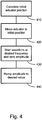
- Fig. 4 is a flow diagram illustrating a startup procedure that can eliminate or at least greatly reduce the occurrence of excess sample deformation during the initial operation of a test.
- initial actuator positions are calculated based on the user-defined axial strain profile and bend angle profile.
- a desired axial strain profile may vary between 2% and 10% and a desired bend angle may vary between 10° and 55°.
- the actuator positions corresponding to the mean strain value of 6% and mean bend angle of 32.5° are calculated using a geometric model of the test fixture.
- a mean value is selected to initially position the actuators, a range of values may be used that avoid exceeding the extremum values of the desired profiles during the startup procedure.
- any combination of an initial strain value between 4% and 8% (the central half of the 2 - 10% range of the axial strain simulation axis) and an initial bend angle between 21° and 44° (the central half of the 10 - 55° range of the bend angle simulation axis) may be used to calculate the initial actuator positions.
- one-half of the constant value is used as the mean value for that simulation axis. For example, if the user desires a fatigue test run at a constant axial strain of 12%, a value of 6% is used for the calculation of the initial actuator positions.
- step 420 actuators are moved to the initial position calculated in the previous step.
- the extensor actuator 130 is operated to disengage the bend tool 119 from contacting the sample holder 101.
- the scissors actuator 120 is then moved to the calculated initial position for the scissors actuator 120.
- the extensor actuator is then moved to the calculated initial position for the extensor actuator.
- step 430 the waveform is started at the desired frequency but with the amplitudes set initially to zero.
- step 440 the amplitudes are increased to the desired values at a rate that is preferably less than 10% per cycle and more preferably about 1% per cycle.
- step 420 may be performed before step 430. In other embodiments, step 420 may be performed with step 430.
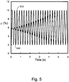
- Fig. 5 is a plot of the axial strain as a function of time using the startup procedure shown in Fig. 4 .
- reference 510 indicates the user-desired axial strain profile
- reference 550 indicates the calculated axial strain based on the drive shaft positions of the scissors actuator and the extensor actuator.
- the desired axial strain profile is roughly sinusoidal having a frequency of about 4 Hz and a peak-to-peak range of about +2% to +10%.
- the axial strain calculated from the positions of the scissors and extensor actuators shows increasing amplitude to the desired amplitude within a few seconds.
- Fig. 6 is a plot of the bend angle as a function of time using the startup procedure shown in Fig. 4 .
- the desired bend angle profile is not shown in Fig. 6 to more clearly show the bend angle derived from the positions of the scissors and extensor actuators.
- the user-defined bend profile is roughly sinusoidal with a 4 Hz frequency and a peak-to-peak range of about 10° to about 55°.
- the bend angle starts at roughly the midpoint in the peak-to-peak range and follows a roughly sinusoidal profile at about 4 Hz with gradually increasing amplitude until it matches the user-defined profile at around 5 seconds.
- Fig. 7 is a plot of the axial strain as a function of time using the startup procedure shown in Fig. 4 .
- the user has selected a constant axial strain of about 12% and a bend profile that is roughly sinusoidal with a frequency of about 4 Hz with a peak-to-peak range of 85° to 100°.
- the desired profile is indicated by reference 710 and includes the user-selected constant axial strain of about 12% after about 5 seconds from startup and a startup ramp starting at roughly one-half of the user-selected axial strain value and increasing to the user-selected value at about 5 seconds.
- Reference 750 shows the axial strain calculated from the positions of the scissors and extensor actuators.
- the oscillation in the calculated axial strain is believed to arise because the two actuators are not in the correct position to achieve constant strain and as the amplitude is increased, one of the actuators may reach its desired position before the other actuator reaches its corresponding desired position. As the two actuators reach their respective positions, the amplitude of the axial strain oscillation decreases until it matches the user-selected constant strain of 12%.
- Fig. 8 is a plot of the bend angle as a function of time using the same initial conditions and startup procedure shown in Fig. 7 .
- the desired bend angle profile is not shown in Fig. 8 to more clearly show the bend angle derived from the positions of the scissors and extensor actuators.
- the slight asymmetry in the bend angle envelop is believed due to the asymmetric axial strain profile shown in Fig. 7 and the coupling between scissors and extensor actuators.
- Embodiments of the systems and methods described above comprise computer components and computer-implemented steps that will be apparent to those skilled in the art.
- the computer-implemented steps may be stored as computer-executable instructions on a computer-readable medium such as, for example, floppy disks, hard disks, optical disks, Flash ROMS, nonvolatile ROM, and RAM.
- the computer-executable instructions may be executed on a variety of processors such as, for example, microprocessors, digital signal processors, gate arrays, etc.
Landscapes
- Physics & Mathematics (AREA)
- Health & Medical Sciences (AREA)
- Life Sciences & Earth Sciences (AREA)
- Chemical & Material Sciences (AREA)
- Analytical Chemistry (AREA)
- Biochemistry (AREA)
- General Health & Medical Sciences (AREA)
- General Physics & Mathematics (AREA)
- Immunology (AREA)
- Pathology (AREA)
- Investigating Strength Of Materials By Application Of Mechanical Stress (AREA)
Claims (10)
- Anlaufverfahren für ein Mehrachsen-Simulationssystem einschließlich einer Prüfvorrichtung (110) mit einem MIMO-Gestänge, wobei das MIMO-Gestänge von einem ersten Aktor (130) und einem zweiten Aktor (120) angetrieben wird, wobei das MIMO-Gestänge auf einen Probenhalter (101) entlang einer ersten Simulationsachse und einer zweiten Simulationsachse einwirkt, wobei das Verfahren Folgendes umfasst: Entgegennehmen eines ersten benutzerdefinierten Profils und eines zweiten benutzerdefinierten Profils für Proben-Axialdehnung (201) und Proben-Biegewinkel (205);
Berechnen einer Ausgangsposition eines Ermüdungstests für den ersten Aktor (130) auf Basis des ersten und zweiten benutzerdefinierten Profils;
Bewegen des ersten Aktors (130) in die Ausgangsposition;
Betreiben des ersten Aktors (130) gemäß einer Wellenform mit einer anfänglich auf null eingestellten Amplitude, wobei die Amplitude mit einer Rate auf einen gewünschten Wert erhöht wird. - Verfahren nach Anspruch 1, worin die Rate weniger als 9 % pro Zyklus beträgt.
- Verfahren nach Anspruch 1, worin die Rate 1 % pro Zyklus beträgt.
- Verfahren nach Anspruch 1, worin die Ausgangsposition des ersten Aktors (130) ab (a) einem Punkt in einer Region, die eine mittlere Hälfte eines Peak-Peak-Bereichs des ersten benutzerdefinierten Profils enthält, und (b) einem Punkt in einer Region, die eine mittlere Hälfte eines Peak-Peak-Bereichs des zweiten benutzerdefinierten Profils enthält, berechnet wird.
- Verfahren nach Anspruch 1, worin die Ausgangsposition des ersten Aktors (130) ab (a) einem mittleren Wert des ersten benutzerdefinierten Profils und (b) einem mittleren Wert des zweiten benutzerdefinierten Profils berechnet wird.
- Verfahren nach Anspruch 1, worin die Ausgangsposition des ersten Aktors (130) ab der Hälfte eines Wertes des ersten benutzerdefinierten Profils berechnet wird.
- Verfahren nach Anspruch 1, worin der Schritt des Bewegens Folgendes beinhaltet:Betätigen des ersten Aktors (130), um ein die Probe berührendes Biegewerkzeug (119) außer Eingriff zu bringen; Betätigen des zweiten Aktors (120) entsprechend einer für den zweiten Aktor berechneten Ausgangsposition; undBetätigen des ersten Aktors (130) entsprechend der für den ersten Aktor berechneten Ausgangsposition.
- Verfahren nach Anspruch 1, ferner umfassend das Betätigen des zweiten Aktors (120) sowohl gemäß dem ersten benutzerdefinierten Profil als auch dem zweiten benutzerdefinierten Profil.
- Mehrachsen-Simulationssystem, umfassend:eine Prüfvorrichtung (110) mit einem MIMO-Gestänge, wobei das MIMO-Gestänge von einem ersten Aktor (130) und einem zweiten Aktor (120) angetrieben wird, wobei das MIMO-Gestänge auf einen Probenhalter (101) entlang einer ersten Simulationsachse und einer zweiten Simulationsachse einwirkt;ein Steuergerät (160), das konfiguriert ist, umein erstes benutzerdefiniertes Profil und ein zweites benutzerdefiniertes Profil für Proben-Axialdehnung (201) und Proben-Biegewinkel (205) entgegenzunehmen,eine Ausgangsposition eines Ermüdungstests für den ersten Aktor (130) auf Basis des ersten und zweiten benutzerdefinierten Profils zu berechnen;den ersten Aktor (130) in die Ausgangsposition zu bewegen;den ersten Aktor (130) gemäß einer Wellenform mit einer anfänglich auf null eingestellten Amplitude zu betätigen, wobei die Amplitude mit einer Rate auf einen gewünschten Wert erhöht wird.
- System nach Anspruch 9, worin die erste Simulationsachse eine Axialdehnung und die zweite Simulationsachse ein Biegewinkel ist.
Applications Claiming Priority (2)
| Application Number | Priority Date | Filing Date | Title |
|---|---|---|---|
| US12/145,822 US8175833B2 (en) | 2008-06-25 | 2008-06-25 | System and method for multi-axis simulation |
| PCT/US2009/044604 WO2010008674A2 (en) | 2008-06-25 | 2009-05-20 | System and method for multi-axis simulation |
Publications (2)
| Publication Number | Publication Date |
|---|---|
| EP2291634A2 EP2291634A2 (de) | 2011-03-09 |
| EP2291634B1 true EP2291634B1 (de) | 2018-04-11 |
Family
ID=41395586
Family Applications (1)
| Application Number | Title | Priority Date | Filing Date |
|---|---|---|---|
| EP09789710.2A Active EP2291634B1 (de) | 2008-06-25 | 2009-05-20 | Vorrichtung und verfahren zur mehr-achsen simulation |
Country Status (3)
| Country | Link |
|---|---|
| US (1) | US8175833B2 (de) |
| EP (1) | EP2291634B1 (de) |
| WO (1) | WO2010008674A2 (de) |
Families Citing this family (4)
| Publication number | Priority date | Publication date | Assignee | Title |
|---|---|---|---|---|
| US7966890B2 (en) * | 2008-06-25 | 2011-06-28 | Bose Corporation | High frequency multi-axis simulation system |
| WO2012049679A2 (en) | 2010-10-12 | 2012-04-19 | Endospan Ltd. | Accelerated bench-testing of medical devices |
| JP6912790B2 (ja) * | 2017-08-24 | 2021-08-04 | ユアサシステム機器株式会社 | 変形試験器 |
| JP7784303B2 (ja) | 2019-01-22 | 2025-12-11 | ウオーターズ・テクノロジーズ・コーポレイシヨン | リニアモーター |
Citations (1)
| Publication number | Priority date | Publication date | Assignee | Title |
|---|---|---|---|---|
| US20040016301A1 (en) * | 2002-07-29 | 2004-01-29 | Moreno Michael R. | Method and apparatus for vascular durability and fatigue testing |
Family Cites Families (5)
| Publication number | Priority date | Publication date | Assignee | Title |
|---|---|---|---|---|
| US4802365A (en) * | 1988-02-22 | 1989-02-07 | Schenck Pegasus Corporation | Multi-axial fatigue testing machine |
| US6718833B2 (en) * | 2001-03-05 | 2004-04-13 | Adtech Systems Research, Inc. | Multiaxial high cycle fatigue test system |
| US7546775B2 (en) * | 2007-06-04 | 2009-06-16 | Bose Corporation | Bend tool |
| US7624648B2 (en) * | 2007-06-26 | 2009-12-01 | Bose Corporation | System and method for multi-axes simulation |
| US7966890B2 (en) | 2008-06-25 | 2011-06-28 | Bose Corporation | High frequency multi-axis simulation system |
-
2008
- 2008-06-25 US US12/145,822 patent/US8175833B2/en not_active Expired - Fee Related
-
2009
- 2009-05-20 WO PCT/US2009/044604 patent/WO2010008674A2/en not_active Ceased
- 2009-05-20 EP EP09789710.2A patent/EP2291634B1/de active Active
Patent Citations (1)
| Publication number | Priority date | Publication date | Assignee | Title |
|---|---|---|---|---|
| US20040016301A1 (en) * | 2002-07-29 | 2004-01-29 | Moreno Michael R. | Method and apparatus for vascular durability and fatigue testing |
Also Published As
| Publication number | Publication date |
|---|---|
| US20090326837A1 (en) | 2009-12-31 |
| EP2291634A2 (de) | 2011-03-09 |
| WO2010008674A3 (en) | 2010-05-14 |
| WO2010008674A2 (en) | 2010-01-21 |
| US8175833B2 (en) | 2012-05-08 |
Similar Documents
| Publication | Publication Date | Title |
|---|---|---|
| EP2304406B1 (de) | Mehrachsiges hochfrequenzsimulationssystem | |
| EP2162722B1 (de) | System und verfahren für multi-achsen simulation | |
| Pappalardo et al. | Hunt–Crossley model based force control for minimally invasive robotic surgery | |
| EP2291634B1 (de) | Vorrichtung und verfahren zur mehr-achsen simulation | |
| US8347738B2 (en) | Sensors and control for an interventional catheter | |
| Menciassi et al. | Force feedback-based microinstrument for measuring tissue properties and pulse in microsurgery | |
| Wang et al. | Haptic feedback and control of a flexible surgical endoscopic robot | |
| Hadi et al. | Developing a novel continuum module actuated by shape memory alloys | |
| US20060070461A1 (en) | Dynamic load fixture for rotary mechanical systems | |
| Zhao et al. | Sensorless force sensing for minimally invasive surgery | |
| CN216651514U (zh) | 具感知反馈的测试系统 | |
| JP2016529528A (ja) | コンプライアントアクチュエータセンブリおよび反復して得られる駆動を有する試験システム | |
| Chioson et al. | Implementation of a bilateral teleoperation haptic feedback controls to robotic minimally invasive surgery | |
| WO2022008880A1 (en) | Characterising the performance of a robotic joint | |
| Zheng et al. | Optimal design of a hybrid compliant mechanism considering the dynamic behavior of membrane-loaded | |
| GU et al. | Design of a multichannel indentation system for measuring biomechanical properties of forearm soft tissues in vivo | |
| Dargahi et al. | An experimental teletaction system for sensing and teleperception of human pulse | |
| Werning et al. | Quantifying Viscous Damping and Stiffness in Parkinsonism Using Data-Driven Model Estimation and Admittance Control | |
| Hariri et al. | Experimental study of nitinol wire arrangements as servo-biomimetics for facial muscles | |
| CN119574283B (zh) | 一种多功能试验平台及使用方法 | |
| Xing et al. | A programmable anisotropic variable stiffness extensible continuum manipulator segment via friction clamping | |
| Ivanova et al. | Experimental studies of the structure of biological tissues through mechanical effects with a smart laparoscopic instrument | |
| CN116135068A (zh) | 具感知反馈的测试系统 | |
| Laier | Feasibility study of a tele-operated surgical device with a dynamic end effector | |
| Renauld et al. | An automated facility for advanced testing of materials |
Legal Events
| Date | Code | Title | Description |
|---|---|---|---|
| PUAI | Public reference made under article 153(3) epc to a published international application that has entered the european phase |
Free format text: ORIGINAL CODE: 0009012 |
|
| 17P | Request for examination filed |
Effective date: 20110117 |
|
| AK | Designated contracting states |
Kind code of ref document: A2 Designated state(s): AT BE BG CH CY CZ DE DK EE ES FI FR GB GR HR HU IE IS IT LI LT LU LV MC MK MT NL NO PL PT RO SE SI SK TR |
|
| AX | Request for extension of the european patent |
Extension state: AL BA RS |
|
| DAX | Request for extension of the european patent (deleted) | ||
| 17Q | First examination report despatched |
Effective date: 20141215 |
|
| RAP1 | Party data changed (applicant data changed or rights of an application transferred) |
Owner name: TA INSTRUMENTS-WATERS LLC |
|
| GRAP | Despatch of communication of intention to grant a patent |
Free format text: ORIGINAL CODE: EPIDOSNIGR1 |
|
| INTG | Intention to grant announced |
Effective date: 20171026 |
|
| GRAS | Grant fee paid |
Free format text: ORIGINAL CODE: EPIDOSNIGR3 |
|
| GRAA | (expected) grant |
Free format text: ORIGINAL CODE: 0009210 |
|
| AK | Designated contracting states |
Kind code of ref document: B1 Designated state(s): AT BE BG CH CY CZ DE DK EE ES FI FR GB GR HR HU IE IS IT LI LT LU LV MC MK MT NL NO PL PT RO SE SI SK TR |
|
| REG | Reference to a national code |
Ref country code: GB Ref legal event code: FG4D |
|
| REG | Reference to a national code |
Ref country code: CH Ref legal event code: EP |
|
| REG | Reference to a national code |
Ref country code: AT Ref legal event code: REF Ref document number: 988567 Country of ref document: AT Kind code of ref document: T Effective date: 20180415 |
|
| REG | Reference to a national code |
Ref country code: IE Ref legal event code: FG4D |
|
| REG | Reference to a national code |
Ref country code: DE Ref legal event code: R096 Ref document number: 602009051756 Country of ref document: DE |
|
| REG | Reference to a national code |
Ref country code: NL Ref legal event code: MP Effective date: 20180411 |
|
| REG | Reference to a national code |
Ref country code: LT Ref legal event code: MG4D |
|
| PG25 | Lapsed in a contracting state [announced via postgrant information from national office to epo] |
Ref country code: NL Free format text: LAPSE BECAUSE OF FAILURE TO SUBMIT A TRANSLATION OF THE DESCRIPTION OR TO PAY THE FEE WITHIN THE PRESCRIBED TIME-LIMIT Effective date: 20180411 |
|
| PG25 | Lapsed in a contracting state [announced via postgrant information from national office to epo] |
Ref country code: FI Free format text: LAPSE BECAUSE OF FAILURE TO SUBMIT A TRANSLATION OF THE DESCRIPTION OR TO PAY THE FEE WITHIN THE PRESCRIBED TIME-LIMIT Effective date: 20180411 Ref country code: BG Free format text: LAPSE BECAUSE OF FAILURE TO SUBMIT A TRANSLATION OF THE DESCRIPTION OR TO PAY THE FEE WITHIN THE PRESCRIBED TIME-LIMIT Effective date: 20180711 Ref country code: NO Free format text: LAPSE BECAUSE OF FAILURE TO SUBMIT A TRANSLATION OF THE DESCRIPTION OR TO PAY THE FEE WITHIN THE PRESCRIBED TIME-LIMIT Effective date: 20180711 Ref country code: LT Free format text: LAPSE BECAUSE OF FAILURE TO SUBMIT A TRANSLATION OF THE DESCRIPTION OR TO PAY THE FEE WITHIN THE PRESCRIBED TIME-LIMIT Effective date: 20180411 Ref country code: PL Free format text: LAPSE BECAUSE OF FAILURE TO SUBMIT A TRANSLATION OF THE DESCRIPTION OR TO PAY THE FEE WITHIN THE PRESCRIBED TIME-LIMIT Effective date: 20180411 Ref country code: SE Free format text: LAPSE BECAUSE OF FAILURE TO SUBMIT A TRANSLATION OF THE DESCRIPTION OR TO PAY THE FEE WITHIN THE PRESCRIBED TIME-LIMIT Effective date: 20180411 Ref country code: ES Free format text: LAPSE BECAUSE OF FAILURE TO SUBMIT A TRANSLATION OF THE DESCRIPTION OR TO PAY THE FEE WITHIN THE PRESCRIBED TIME-LIMIT Effective date: 20180411 |
|
| PG25 | Lapsed in a contracting state [announced via postgrant information from national office to epo] |
Ref country code: LV Free format text: LAPSE BECAUSE OF FAILURE TO SUBMIT A TRANSLATION OF THE DESCRIPTION OR TO PAY THE FEE WITHIN THE PRESCRIBED TIME-LIMIT Effective date: 20180411 Ref country code: HR Free format text: LAPSE BECAUSE OF FAILURE TO SUBMIT A TRANSLATION OF THE DESCRIPTION OR TO PAY THE FEE WITHIN THE PRESCRIBED TIME-LIMIT Effective date: 20180411 Ref country code: GR Free format text: LAPSE BECAUSE OF FAILURE TO SUBMIT A TRANSLATION OF THE DESCRIPTION OR TO PAY THE FEE WITHIN THE PRESCRIBED TIME-LIMIT Effective date: 20180712 |
|
| REG | Reference to a national code |
Ref country code: CH Ref legal event code: PL |
|
| REG | Reference to a national code |
Ref country code: AT Ref legal event code: MK05 Ref document number: 988567 Country of ref document: AT Kind code of ref document: T Effective date: 20180411 |
|
| PG25 | Lapsed in a contracting state [announced via postgrant information from national office to epo] |
Ref country code: PT Free format text: LAPSE BECAUSE OF FAILURE TO SUBMIT A TRANSLATION OF THE DESCRIPTION OR TO PAY THE FEE WITHIN THE PRESCRIBED TIME-LIMIT Effective date: 20180813 |
|
| REG | Reference to a national code |
Ref country code: DE Ref legal event code: R097 Ref document number: 602009051756 Country of ref document: DE |
|
| REG | Reference to a national code |
Ref country code: BE Ref legal event code: MM Effective date: 20180531 |
|
| PG25 | Lapsed in a contracting state [announced via postgrant information from national office to epo] |
Ref country code: EE Free format text: LAPSE BECAUSE OF FAILURE TO SUBMIT A TRANSLATION OF THE DESCRIPTION OR TO PAY THE FEE WITHIN THE PRESCRIBED TIME-LIMIT Effective date: 20180411 Ref country code: AT Free format text: LAPSE BECAUSE OF FAILURE TO SUBMIT A TRANSLATION OF THE DESCRIPTION OR TO PAY THE FEE WITHIN THE PRESCRIBED TIME-LIMIT Effective date: 20180411 Ref country code: DK Free format text: LAPSE BECAUSE OF FAILURE TO SUBMIT A TRANSLATION OF THE DESCRIPTION OR TO PAY THE FEE WITHIN THE PRESCRIBED TIME-LIMIT Effective date: 20180411 Ref country code: CZ Free format text: LAPSE BECAUSE OF FAILURE TO SUBMIT A TRANSLATION OF THE DESCRIPTION OR TO PAY THE FEE WITHIN THE PRESCRIBED TIME-LIMIT Effective date: 20180411 Ref country code: RO Free format text: LAPSE BECAUSE OF FAILURE TO SUBMIT A TRANSLATION OF THE DESCRIPTION OR TO PAY THE FEE WITHIN THE PRESCRIBED TIME-LIMIT Effective date: 20180411 Ref country code: MC Free format text: LAPSE BECAUSE OF FAILURE TO SUBMIT A TRANSLATION OF THE DESCRIPTION OR TO PAY THE FEE WITHIN THE PRESCRIBED TIME-LIMIT Effective date: 20180411 Ref country code: SK Free format text: LAPSE BECAUSE OF FAILURE TO SUBMIT A TRANSLATION OF THE DESCRIPTION OR TO PAY THE FEE WITHIN THE PRESCRIBED TIME-LIMIT Effective date: 20180411 |
|
| PLBE | No opposition filed within time limit |
Free format text: ORIGINAL CODE: 0009261 |
|
| STAA | Information on the status of an ep patent application or granted ep patent |
Free format text: STATUS: NO OPPOSITION FILED WITHIN TIME LIMIT |
|
| REG | Reference to a national code |
Ref country code: IE Ref legal event code: MM4A |
|
| PG25 | Lapsed in a contracting state [announced via postgrant information from national office to epo] |
Ref country code: CH Free format text: LAPSE BECAUSE OF NON-PAYMENT OF DUE FEES Effective date: 20180531 Ref country code: LI Free format text: LAPSE BECAUSE OF NON-PAYMENT OF DUE FEES Effective date: 20180531 Ref country code: IT Free format text: LAPSE BECAUSE OF FAILURE TO SUBMIT A TRANSLATION OF THE DESCRIPTION OR TO PAY THE FEE WITHIN THE PRESCRIBED TIME-LIMIT Effective date: 20180411 |
|
| 26N | No opposition filed |
Effective date: 20190114 |
|
| PG25 | Lapsed in a contracting state [announced via postgrant information from national office to epo] |
Ref country code: LU Free format text: LAPSE BECAUSE OF NON-PAYMENT OF DUE FEES Effective date: 20180520 |
|
| PG25 | Lapsed in a contracting state [announced via postgrant information from national office to epo] |
Ref country code: FR Free format text: LAPSE BECAUSE OF NON-PAYMENT OF DUE FEES Effective date: 20180611 Ref country code: IE Free format text: LAPSE BECAUSE OF NON-PAYMENT OF DUE FEES Effective date: 20180520 |
|
| PG25 | Lapsed in a contracting state [announced via postgrant information from national office to epo] |
Ref country code: BE Free format text: LAPSE BECAUSE OF NON-PAYMENT OF DUE FEES Effective date: 20180531 Ref country code: SI Free format text: LAPSE BECAUSE OF FAILURE TO SUBMIT A TRANSLATION OF THE DESCRIPTION OR TO PAY THE FEE WITHIN THE PRESCRIBED TIME-LIMIT Effective date: 20180411 |
|
| PG25 | Lapsed in a contracting state [announced via postgrant information from national office to epo] |
Ref country code: MT Free format text: LAPSE BECAUSE OF NON-PAYMENT OF DUE FEES Effective date: 20180520 |
|
| PG25 | Lapsed in a contracting state [announced via postgrant information from national office to epo] |
Ref country code: TR Free format text: LAPSE BECAUSE OF FAILURE TO SUBMIT A TRANSLATION OF THE DESCRIPTION OR TO PAY THE FEE WITHIN THE PRESCRIBED TIME-LIMIT Effective date: 20180411 |
|
| PG25 | Lapsed in a contracting state [announced via postgrant information from national office to epo] |
Ref country code: HU Free format text: LAPSE BECAUSE OF FAILURE TO SUBMIT A TRANSLATION OF THE DESCRIPTION OR TO PAY THE FEE WITHIN THE PRESCRIBED TIME-LIMIT; INVALID AB INITIO Effective date: 20090520 |
|
| PG25 | Lapsed in a contracting state [announced via postgrant information from national office to epo] |
Ref country code: CY Free format text: LAPSE BECAUSE OF FAILURE TO SUBMIT A TRANSLATION OF THE DESCRIPTION OR TO PAY THE FEE WITHIN THE PRESCRIBED TIME-LIMIT Effective date: 20180411 Ref country code: MK Free format text: LAPSE BECAUSE OF NON-PAYMENT OF DUE FEES Effective date: 20180411 |
|
| PG25 | Lapsed in a contracting state [announced via postgrant information from national office to epo] |
Ref country code: IS Free format text: LAPSE BECAUSE OF FAILURE TO SUBMIT A TRANSLATION OF THE DESCRIPTION OR TO PAY THE FEE WITHIN THE PRESCRIBED TIME-LIMIT Effective date: 20180811 |
|
| P01 | Opt-out of the competence of the unified patent court (upc) registered |
Effective date: 20230609 |
|
| P02 | Opt-out of the competence of the unified patent court (upc) changed |
Effective date: 20230619 |
|
| PGFP | Annual fee paid to national office [announced via postgrant information from national office to epo] |
Ref country code: DE Payment date: 20250423 Year of fee payment: 17 |
|
| PGFP | Annual fee paid to national office [announced via postgrant information from national office to epo] |
Ref country code: GB Payment date: 20250423 Year of fee payment: 17 |