EP2290773A2 - Differenzstromwandler und Differenzstromschutzgerät - Google Patents
Differenzstromwandler und Differenzstromschutzgerät Download PDFInfo
- Publication number
- EP2290773A2 EP2290773A2 EP10173348A EP10173348A EP2290773A2 EP 2290773 A2 EP2290773 A2 EP 2290773A2 EP 10173348 A EP10173348 A EP 10173348A EP 10173348 A EP10173348 A EP 10173348A EP 2290773 A2 EP2290773 A2 EP 2290773A2
- Authority
- EP
- European Patent Office
- Prior art keywords
- dct
- value
- secondary coil
- iron core
- sampling circuit
- Prior art date
- Legal status (The legal status is an assumption and is not a legal conclusion. Google has not performed a legal analysis and makes no representation as to the accuracy of the status listed.)
- Granted
Links
Images
Classifications
-
- H—ELECTRICITY
- H02—GENERATION; CONVERSION OR DISTRIBUTION OF ELECTRIC POWER
- H02H—EMERGENCY PROTECTIVE CIRCUIT ARRANGEMENTS
- H02H3/00—Emergency protective circuit arrangements for automatic disconnection directly responsive to an undesired change from normal electric working condition with or without subsequent reconnection ; integrated protection
- H02H3/26—Emergency protective circuit arrangements for automatic disconnection directly responsive to an undesired change from normal electric working condition with or without subsequent reconnection ; integrated protection responsive to difference between voltages or between currents; responsive to phase angle between voltages or between currents
- H02H3/32—Emergency protective circuit arrangements for automatic disconnection directly responsive to an undesired change from normal electric working condition with or without subsequent reconnection ; integrated protection responsive to difference between voltages or between currents; responsive to phase angle between voltages or between currents involving comparison of the voltage or current values at corresponding points in different conductors of a single system, e.g. of currents in go and return conductors
- H02H3/33—Emergency protective circuit arrangements for automatic disconnection directly responsive to an undesired change from normal electric working condition with or without subsequent reconnection ; integrated protection responsive to difference between voltages or between currents; responsive to phase angle between voltages or between currents involving comparison of the voltage or current values at corresponding points in different conductors of a single system, e.g. of currents in go and return conductors using summation current transformers
-
- H—ELECTRICITY
- H02—GENERATION; CONVERSION OR DISTRIBUTION OF ELECTRIC POWER
- H02H—EMERGENCY PROTECTIVE CIRCUIT ARRANGEMENTS
- H02H1/00—Details of emergency protective circuit arrangements
- H02H1/0092—Details of emergency protective circuit arrangements concerning the data processing means, e.g. expert systems, neural networks
Definitions
- the present invention relates to the field of electric current leakage protection technology and, particularly, to a residual current operated protective device (RCD) and a differential current transformer (DCT) in the residual current operated protective device RCD.
- RCD residual current operated protective device
- DCT differential current transformer
- a residual current operated protective device RCD is a current operated electric leakage protective device, and the differential current transformer DCT is an important component in the RCD, which is used to detect whether there is any residual current (that is the leakage current) in an electric power circuit.
- the structure of a DCT is similar to that of a transformer, comprising an iron core and two mutually insulated coils wound on the iron core, so that when there is a residual current in the primary coil side, the secondary coil will then have an induced current.
- a DCT can also include a shielded housing and a bracket.
- the primary coil is connected with the power line to be detected or an electric power circuit (such as a phase line and a zero line) to be detected passes though the iron core directly as the primary coil, and the secondary coil is connected to a switch device in the RCD.
- an electric power circuit such as a phase line and a zero line
- the current in the circuit is in a balanced state, the vector sum of the DCT currents is zero, there is no magnetic flux change in the iron core, and therefore there will be no induced current in the secondary coil, with the switching device of the RCD being in the turn-on state.
- the vector sum of the currents is not zero, there is magnetic flux changes in the iron core, and it will induce a current in the secondary coil, and when this current value reaches a threshold limit of the RCD, the power will be turned off by the switching device.
- Linearity and sensitivity are two important performance criteria of the DCT, which determine the stability and reliability of the RCD.
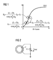
- the linearity of a DCT is determined by the working position of the iron core in the B-H curve shown in Fig. 1 (the horizontal axis is the magnetic field strength H, and vertical axis is the magnetic flux density B), in which, B can be calculated by equation (1).
- B Z 1 + Z ⁇ ⁇ I 1 4.44 ⁇ f ⁇ N 2 2 ⁇ kS
- Fig. 2 is a schematic diagram of the sampling circuit of the RCD in the prior art, in which the input end and output end of the secondary coil wound on the DCT iron core are connected respectively to the two ends of the load resistance Z 1 , with the load resistance Z 1 being a variable resistor.
- the sampling circuit After the sampling circuit has obtained a residual current, it also needs to be converted and transmitted by intermediate mechanisms (such as to be amplified by a amplifier circuit), and then sent into a processing unit to make a judgment, and when the residual current reaches a threshold value, an executing mechanism will be operated. Based on the sampling circuit shown in Fig.
- n 1 is the DCT sensitivity of the sampling circuit based on that shown in Fig. 2
- I ⁇ n is the rated residual operated current value
- V ⁇ n is the output voltage corresponding to I ⁇ n
- Z 1 is the load resistance
- Z' is the resistance of the secondary coil
- f is the signal frequency
- N 2 is the number of turns of the secondary coil
- k is the lamination coefficient of the iron core
- S is the cross-sectional area of the iron core
- L is the length of the magnetic path
- ⁇ is the loss angle of the iron core
- ⁇ is the power factor angle of the secondary coil side
- ⁇ is magnetic conductivity of the iron core.
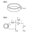
- the value of the rated residual operated current I ⁇ n can be set according to the actual needs, under the normal circumstances, the lowest value of the residual operated current I ⁇ n is 30 mA, which is also the operating value required for the electric shock protection of a human body, in order to ensure enough linearity and sensitivity of DCT in such low current value, a DCT needs to have certain volume, that is shown in Fig. 3, and Fig. 3 is a schematic diagram of the iron core in the DCT of a type A RCD in the prior art, in which it can be seen that the height of the iron core of the DCT should be at least 10 mm, so as to have the specific iron core cross-sectional area S .
- the object of the present invention is to solve the abovementioned problems.
- the present invention on the one hand provides a differential current transformer (DCT), and on the other hand, provides a residual current operated protective device (RCD), so as to reduce the volume of the residual current operated protective device RCD.
- DCT differential current transformer
- RCD residual current operated protective device
- the differential current transformer (DCT) provided by the present invention comprises: an iron core and a secondary coil wound on said iron core, characterized in that said DCT is connected to a sampling circuit, said sampling circuit is a sampling circuit dual-regulated by both load resistance and amplifier feedback loop resistance.
- said sampling circuit comprises: the load resistance Z 1 connected to one end of said secondary coil, an amplifier connected to said load resistance Z 1 in series and the feedback resistance Z 2 in said amplifier feedback loop; wherein, the other end of the secondary coil and the non-inverting input of the amplifier are connected to a reference voltage; and the load resistance Z 1 and the feedback resistance Z 2 are adjustable resistors.
- the height of said iron core is less than 10 mm.
- the residual current operated protective device (RCD) provided by the present invention comprises: the differential current transformer (DCT) and a sampling circuit, said differential current transformer (DCT) comprises an iron core and a secondary coil wound on said iron core, characterized in that said sampling circuit is a sampling circuit dual-regulated by both load resistance and amplifier feedback loop resistance.
- said sampling circuit comprises: the load resistance Z 1 connected to one end of said secondary coil, the amplifier connected to the load resistance Z 1 in series and the feedback resistance Z 2 in said amplifier feedback loop; wherein, the other end of the secondary coil and the amplifier non-inverting input are connected to a reference voltage; and the load resistance Z 1 and the feedback resistance Z 2 are adjustable resistors.
- the height of said iron core is less than 10 mm.
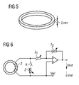
- the height of said iron core is 2 mm.
- the differential current transformer DCT can have a smaller core size, thus reducing the volume of residual current operated protective device RCD on the basis of the reduced size of differential current transformer DCT.
- the volume of a residual current operated protective device can be reduced by providing a differential current transformer (DCT) of a small size
- the DCT iron core can be designed with a size (such as height) smaller than the size (such as height) of the DCT iron core in the prior art.
- the height of the iron core in the prior art is referred to as the first height in the present application, then the height of the iron core of the small size DCT in the present application can be smaller than the first height.
- a new RCD sampling circuit is provided, which is a dual-regulator circuit.
- Fig. 4 is a schematic diagram of a sampling circuit in embodiment one of the present invention.
- the sampling circuit comprises: a load resistance (Z1) connected to one end of the secondary coil in the DCT, an amplifier connected to the load resistance Z 1 in series and a feedback resistor Z 2 in said amplifier feedback loop (with the two ends of the feedback resistor Z 2 connected respectively to the output and the inverting input of the amplifier).
- the other end of the secondary coil and the non-inverting input of the amplifier are connected to a reference voltage; and the load resistance Z 1 and the feedback resistance Z 2 are both adjustable resistors.
- flux density B is still calculated according to equation (1), after the height of the DCT iron core has been reduced, the cross-sectional area S of the DCT iron core is reduced accordingly, then by adjusting the value of the load resistance Z 1 , the value of flux density B is still maintained at B 1 , accordingly, the working position of the DCT iron core is maintained at the corresponding rational position of B 1 , leading to the good linearity of DCT.
- the sensitivity of the DCT can be corrected by adjusting the feedback resistance Z 2 of the amplifier feedback loop, so as to make the DCT maintain a quite good sensitivity thereof.
- N 2 is the number of turns of the secondary coil
- k 1 is virtual value coefficient
- k 2 is the maximum measurable value coefficient
- I ⁇ is the cut-off value of the rated residual operating current
- I out_m is the amplifier's output driving capacity
- the amplifier output corresponding to 135° pulsed DC signal peak is the largest, the virtual value coefficient k 1 is 4.69; in addition, k 2 usually can take 10, and then DCT measurement range is 0-10 I ⁇ n .
- the rated residual operating current cut-off value I ⁇ is 1.34 A, if taking the integer 1A as the boundary of protection for the rated residual current, for a rated residual operating current above 1A, the sampling circuit shown in Fig. 4 will no longer apply.
- the value of the secondary coil resistor Z' will be far greater than that of the load resistance Z 1 , for example, when the value of the secondary coil resistor Z' of DCT is 60 ⁇ , the value of the corresponding load resistance which corresponds to the rated residual operating current value set at 5A is only 7.6 ⁇ , so it can be seen that the latter is only 12.6% of the former.
- the secondary coil With the reduction in the height of the DCT iron core, the secondary coil will be reduced accordingly, which in turn leads to the reduction of the value of the secondary coil resistance Z' . Therefore, when the rated residual operating current value is set high, the working position of the DCT iron core in the prior art sampling circuit, with the reduction of the secondary coil resistor Z' , can be maintained at the rational working position.
- the difference of B is very small, that is, when the rated residual operating current is set high, on the basis of the prior art sampling circuit, DCT linearity affected by the reduction of the height of the DCT is quite small.
- the dual-regulated sampling circuit shown in Fig. 4 can be connected in parallel with the sampling circuit in the prior art as shown in Fig. 2 in the embodiment of the present invention, and be selected by switching, so that when the value of the rated residual operating current is quite low, the dual-regulated sampling circuit shown in Fig. 4 is used, and when the value of the rated residual operating current is rather high, the prior art sampling circuit shown in Fig. 2 is used.
- Fig. 6 is a schematic diagram of the sampling circuit in embodiment two of the present invention.
- the sampling circuit on the basis of the sampling circuit shown in Fig. 4 further comprises: a first adjustable resistor Z connected respectively to both ends of the secondary coil, and there is a switch K between the first adjustable resistance Z and the secondary coil.
- the rated residual operating current cut-off value I ⁇ can be obtained, so that when the set rated residual operating current value is smaller than or equal to the rated residual operating current cut-off value I ⁇ , the switch K is turned off, and when the set rated residual operating current value is larger than the rated residual operating current cut-off value I ⁇ n , the switch K is turned on.
- Fig. 6 is the sampling circuit shown in Fig. 4
- Z 1 is the load resistance
- Z is the load resistance, which is equivalent to Z 1 as shown in Fig. 2
- Z 1 in Fig. 6 is a part of the voltage amplifier circuit.
Landscapes
- Engineering & Computer Science (AREA)
- Power Engineering (AREA)
- Transformers For Measuring Instruments (AREA)
- Amplifiers (AREA)
Applications Claiming Priority (1)
| Application Number | Priority Date | Filing Date | Title |
|---|---|---|---|
| CN200910171625.3A CN102005721B (zh) | 2009-08-31 | 2009-08-31 | 一种差动电流互感器及剩余电流动作保护器 |
Publications (3)
| Publication Number | Publication Date |
|---|---|
| EP2290773A2 true EP2290773A2 (de) | 2011-03-02 |
| EP2290773A3 EP2290773A3 (de) | 2013-03-20 |
| EP2290773B1 EP2290773B1 (de) | 2015-01-28 |
Family
ID=42669824
Family Applications (1)
| Application Number | Title | Priority Date | Filing Date |
|---|---|---|---|
| EP20100173348 Not-in-force EP2290773B1 (de) | 2009-08-31 | 2010-08-19 | Differenzstromwandler und Differenzstromschutzgerät |
Country Status (2)
| Country | Link |
|---|---|
| EP (1) | EP2290773B1 (de) |
| CN (1) | CN102005721B (de) |
Cited By (1)
| Publication number | Priority date | Publication date | Assignee | Title |
|---|---|---|---|---|
| WO2013017934A1 (en) * | 2011-07-29 | 2013-02-07 | Eaton Corporation | Miniature neutral toroidal current transformer |
Families Citing this family (2)
| Publication number | Priority date | Publication date | Assignee | Title |
|---|---|---|---|---|
| CN106526405A (zh) * | 2016-12-09 | 2017-03-22 | 惠州市丝鹭新能源科技有限公司 | 一种充电桩用a型剩余电流检测电路模块 |
| CN109188048A (zh) * | 2018-07-31 | 2019-01-11 | 中国地质大学(武汉) | 一种基于无源零磁通的非接触式微弱电流检测传感器 |
Family Cites Families (5)
| Publication number | Priority date | Publication date | Assignee | Title |
|---|---|---|---|---|
| US4685022A (en) * | 1985-05-10 | 1987-08-04 | Square D Company | Ground fault circuit interrupter capable of deriving energy from ground fault current in order to achieve circuit interruption in the presence of a reduced supply voltage |
| CN2323378Y (zh) * | 1997-11-05 | 1999-06-09 | 西安交通大学 | 宽频带故障放电耦合器 |
| FR2774822B1 (fr) * | 1998-02-11 | 2000-03-17 | Schneider Electric Ind Sa | Dispositif de protection differentielle |
| US6850394B2 (en) * | 2002-08-23 | 2005-02-01 | Cheil Electric Wiring Devices Co. | Apparatus and method for determining mis-wiring in a ground fault circuit interrupter |
| US7079365B2 (en) * | 2002-11-22 | 2006-07-18 | Square D Company | Electrical fault detection system |
-
2009
- 2009-08-31 CN CN200910171625.3A patent/CN102005721B/zh not_active Expired - Fee Related
-
2010
- 2010-08-19 EP EP20100173348 patent/EP2290773B1/de not_active Not-in-force
Non-Patent Citations (1)
| Title |
|---|
| None |
Cited By (1)
| Publication number | Priority date | Publication date | Assignee | Title |
|---|---|---|---|---|
| WO2013017934A1 (en) * | 2011-07-29 | 2013-02-07 | Eaton Corporation | Miniature neutral toroidal current transformer |
Also Published As
| Publication number | Publication date |
|---|---|
| EP2290773A3 (de) | 2013-03-20 |
| EP2290773B1 (de) | 2015-01-28 |
| CN102005721A (zh) | 2011-04-06 |
| CN102005721B (zh) | 2014-09-03 |
Similar Documents
| Publication | Publication Date | Title |
|---|---|---|
| US7821253B2 (en) | Direct current measuring device having magnetic sensors for current generated magnetic fields | |
| US9343895B2 (en) | Protection relay for sensitive earth fault protection | |
| EP3161849B1 (de) | Schutzschalter mit thermischer auslöseanorndung und rogowskispule für leiterplatte | |
| US9647446B2 (en) | Electrical switching apparatus including alternating current electronic trip circuit with arc fault detection circuit | |
| EP2290773B1 (de) | Differenzstromwandler und Differenzstromschutzgerät | |
| CN106706999A (zh) | 一种晶闸管接触器电流检测装置 | |
| Taranto et al. | Further investigations on a phasor measurement-based algorithm utilized for voltage instability awareness | |
| KR102407483B1 (ko) | 서지보호기의 수명예측방법 | |
| CN1317166A (zh) | 用于低压电网的保护装置 | |
| US6300856B1 (en) | Electrical transformer | |
| CN103493322B (zh) | 控制高压电网络中的电流中断设备的方法 | |
| CN108172476B (zh) | 具有电流检测组件的小型断路器 | |
| CN101330206A (zh) | 输电线路故障测距的一种方法 | |
| US9384928B2 (en) | Electrical switching apparatus including transductor circuit and alternating current electronic trip circuit | |
| EP3997465B1 (de) | Sensorvorrichtung und sensorverfahren | |
| AU2019447727B2 (en) | Electric line (L) protection device for detecting a leakage fault, a short-circuit, fault, an overcurrent fault and an arc fault | |
| CN207834228U (zh) | 具有新型电流检测组件的小型断路器 | |
| KR102524718B1 (ko) | 저전류 변류기를 이용한 고 서지전류측정 방법 | |
| US20250277823A1 (en) | Current sensor and control method thereof | |
| CN106229134A (zh) | 一种自校验电子式电流互感器及其制造方法 | |
| KR101332941B1 (ko) | 변류기와 mosfet를 이용한 대기전력차단기의 전류 검출 방법 | |
| CN203085989U (zh) | 时控开关综合配电柜 | |
| Guerra et al. | A new current transformer model | |
| CN101303375A (zh) | 高压接地小电流检测方法 | |
| UA81842C2 (uk) | Пристрій для електронної компенсації похибки вимірювальних трансформаторів напруги |
Legal Events
| Date | Code | Title | Description |
|---|---|---|---|
| PUAI | Public reference made under article 153(3) epc to a published international application that has entered the european phase |
Free format text: ORIGINAL CODE: 0009012 |
|
| AK | Designated contracting states |
Kind code of ref document: A2 Designated state(s): AL AT BE BG CH CY CZ DE DK EE ES FI FR GB GR HR HU IE IS IT LI LT LU LV MC MK MT NL NO PL PT RO SE SI SK SM TR |
|
| AX | Request for extension of the european patent |
Extension state: BA ME RS |
|
| PUAL | Search report despatched |
Free format text: ORIGINAL CODE: 0009013 |
|
| RAP1 | Party data changed (applicant data changed or rights of an application transferred) |
Owner name: SIEMENS AKTIENGESELLSCHAFT |
|
| AK | Designated contracting states |
Kind code of ref document: A3 Designated state(s): AL AT BE BG CH CY CZ DE DK EE ES FI FR GB GR HR HU IE IS IT LI LT LU LV MC MK MT NL NO PL PT RO SE SI SK SM TR |
|
| AX | Request for extension of the european patent |
Extension state: BA ME RS |
|
| RIC1 | Information provided on ipc code assigned before grant |
Ipc: H02H 3/33 20060101ALN20130211BHEP Ipc: H02H 1/00 20060101AFI20130211BHEP Ipc: H02H 3/16 20060101ALI20130211BHEP |
|
| 17P | Request for examination filed |
Effective date: 20130819 |
|
| RBV | Designated contracting states (corrected) |
Designated state(s): AL AT BE BG CH CY CZ DE DK EE ES FI FR GB GR HR HU IE IS IT LI LT LU LV MC MK MT NL NO PL PT RO SE SI SK SM TR |
|
| GRAP | Despatch of communication of intention to grant a patent |
Free format text: ORIGINAL CODE: EPIDOSNIGR1 |
|
| RIC1 | Information provided on ipc code assigned before grant |
Ipc: H02H 3/16 20060101ALI20140717BHEP Ipc: H02H 1/00 20060101AFI20140717BHEP Ipc: H02H 3/33 20060101ALN20140717BHEP |
|
| RIC1 | Information provided on ipc code assigned before grant |
Ipc: H02H 3/16 20060101ALI20140804BHEP Ipc: H02H 1/00 20060101AFI20140804BHEP Ipc: H02H 3/33 20060101ALN20140804BHEP |
|
| INTG | Intention to grant announced |
Effective date: 20140821 |
|
| GRAS | Grant fee paid |
Free format text: ORIGINAL CODE: EPIDOSNIGR3 |
|
| GRAA | (expected) grant |
Free format text: ORIGINAL CODE: 0009210 |
|
| AK | Designated contracting states |
Kind code of ref document: B1 Designated state(s): AL AT BE BG CH CY CZ DE DK EE ES FI FR GB GR HR HU IE IS IT LI LT LU LV MC MK MT NL NO PL PT RO SE SI SK SM TR |
|
| REG | Reference to a national code |
Ref country code: GB Ref legal event code: FG4D |
|
| REG | Reference to a national code |
Ref country code: CH Ref legal event code: EP |
|
| REG | Reference to a national code |
Ref country code: IE Ref legal event code: FG4D |
|
| REG | Reference to a national code |
Ref country code: AT Ref legal event code: REF Ref document number: 708610 Country of ref document: AT Kind code of ref document: T Effective date: 20150315 |
|
| REG | Reference to a national code |
Ref country code: DE Ref legal event code: R096 Ref document number: 602010022082 Country of ref document: DE Effective date: 20150319 |
|
| REG | Reference to a national code |
Ref country code: AT Ref legal event code: MK05 Ref document number: 708610 Country of ref document: AT Kind code of ref document: T Effective date: 20150128 |
|
| REG | Reference to a national code |
Ref country code: NL Ref legal event code: VDEP Effective date: 20150128 |
|
| REG | Reference to a national code |
Ref country code: LT Ref legal event code: MG4D |
|
| PG25 | Lapsed in a contracting state [announced via postgrant information from national office to epo] |
Ref country code: FI Free format text: LAPSE BECAUSE OF FAILURE TO SUBMIT A TRANSLATION OF THE DESCRIPTION OR TO PAY THE FEE WITHIN THE PRESCRIBED TIME-LIMIT Effective date: 20150128 Ref country code: NO Free format text: LAPSE BECAUSE OF FAILURE TO SUBMIT A TRANSLATION OF THE DESCRIPTION OR TO PAY THE FEE WITHIN THE PRESCRIBED TIME-LIMIT Effective date: 20150428 Ref country code: ES Free format text: LAPSE BECAUSE OF FAILURE TO SUBMIT A TRANSLATION OF THE DESCRIPTION OR TO PAY THE FEE WITHIN THE PRESCRIBED TIME-LIMIT Effective date: 20150128 Ref country code: LT Free format text: LAPSE BECAUSE OF FAILURE TO SUBMIT A TRANSLATION OF THE DESCRIPTION OR TO PAY THE FEE WITHIN THE PRESCRIBED TIME-LIMIT Effective date: 20150128 Ref country code: BG Free format text: LAPSE BECAUSE OF FAILURE TO SUBMIT A TRANSLATION OF THE DESCRIPTION OR TO PAY THE FEE WITHIN THE PRESCRIBED TIME-LIMIT Effective date: 20150428 Ref country code: SE Free format text: LAPSE BECAUSE OF FAILURE TO SUBMIT A TRANSLATION OF THE DESCRIPTION OR TO PAY THE FEE WITHIN THE PRESCRIBED TIME-LIMIT Effective date: 20150128 Ref country code: HR Free format text: LAPSE BECAUSE OF FAILURE TO SUBMIT A TRANSLATION OF THE DESCRIPTION OR TO PAY THE FEE WITHIN THE PRESCRIBED TIME-LIMIT Effective date: 20150128 |
|
| PG25 | Lapsed in a contracting state [announced via postgrant information from national office to epo] |
Ref country code: IS Free format text: LAPSE BECAUSE OF FAILURE TO SUBMIT A TRANSLATION OF THE DESCRIPTION OR TO PAY THE FEE WITHIN THE PRESCRIBED TIME-LIMIT Effective date: 20150528 Ref country code: NL Free format text: LAPSE BECAUSE OF FAILURE TO SUBMIT A TRANSLATION OF THE DESCRIPTION OR TO PAY THE FEE WITHIN THE PRESCRIBED TIME-LIMIT Effective date: 20150128 Ref country code: AT Free format text: LAPSE BECAUSE OF FAILURE TO SUBMIT A TRANSLATION OF THE DESCRIPTION OR TO PAY THE FEE WITHIN THE PRESCRIBED TIME-LIMIT Effective date: 20150128 Ref country code: GR Free format text: LAPSE BECAUSE OF FAILURE TO SUBMIT A TRANSLATION OF THE DESCRIPTION OR TO PAY THE FEE WITHIN THE PRESCRIBED TIME-LIMIT Effective date: 20150429 Ref country code: LV Free format text: LAPSE BECAUSE OF FAILURE TO SUBMIT A TRANSLATION OF THE DESCRIPTION OR TO PAY THE FEE WITHIN THE PRESCRIBED TIME-LIMIT Effective date: 20150128 Ref country code: PL Free format text: LAPSE BECAUSE OF FAILURE TO SUBMIT A TRANSLATION OF THE DESCRIPTION OR TO PAY THE FEE WITHIN THE PRESCRIBED TIME-LIMIT Effective date: 20150128 |
|
| REG | Reference to a national code |
Ref country code: DE Ref legal event code: R097 Ref document number: 602010022082 Country of ref document: DE |
|
| PG25 | Lapsed in a contracting state [announced via postgrant information from national office to epo] |
Ref country code: DK Free format text: LAPSE BECAUSE OF FAILURE TO SUBMIT A TRANSLATION OF THE DESCRIPTION OR TO PAY THE FEE WITHIN THE PRESCRIBED TIME-LIMIT Effective date: 20150128 Ref country code: SK Free format text: LAPSE BECAUSE OF FAILURE TO SUBMIT A TRANSLATION OF THE DESCRIPTION OR TO PAY THE FEE WITHIN THE PRESCRIBED TIME-LIMIT Effective date: 20150128 Ref country code: CZ Free format text: LAPSE BECAUSE OF FAILURE TO SUBMIT A TRANSLATION OF THE DESCRIPTION OR TO PAY THE FEE WITHIN THE PRESCRIBED TIME-LIMIT Effective date: 20150128 Ref country code: RO Free format text: LAPSE BECAUSE OF FAILURE TO SUBMIT A TRANSLATION OF THE DESCRIPTION OR TO PAY THE FEE WITHIN THE PRESCRIBED TIME-LIMIT Effective date: 20150128 Ref country code: EE Free format text: LAPSE BECAUSE OF FAILURE TO SUBMIT A TRANSLATION OF THE DESCRIPTION OR TO PAY THE FEE WITHIN THE PRESCRIBED TIME-LIMIT Effective date: 20150128 |
|
| PLBE | No opposition filed within time limit |
Free format text: ORIGINAL CODE: 0009261 |
|
| STAA | Information on the status of an ep patent application or granted ep patent |
Free format text: STATUS: NO OPPOSITION FILED WITHIN TIME LIMIT |
|
| 26N | No opposition filed |
Effective date: 20151029 |
|
| PG25 | Lapsed in a contracting state [announced via postgrant information from national office to epo] |
Ref country code: SI Free format text: LAPSE BECAUSE OF FAILURE TO SUBMIT A TRANSLATION OF THE DESCRIPTION OR TO PAY THE FEE WITHIN THE PRESCRIBED TIME-LIMIT Effective date: 20150128 |
|
| PG25 | Lapsed in a contracting state [announced via postgrant information from national office to epo] |
Ref country code: LU Free format text: LAPSE BECAUSE OF FAILURE TO SUBMIT A TRANSLATION OF THE DESCRIPTION OR TO PAY THE FEE WITHIN THE PRESCRIBED TIME-LIMIT Effective date: 20150819 Ref country code: MC Free format text: LAPSE BECAUSE OF FAILURE TO SUBMIT A TRANSLATION OF THE DESCRIPTION OR TO PAY THE FEE WITHIN THE PRESCRIBED TIME-LIMIT Effective date: 20150128 |
|
| REG | Reference to a national code |
Ref country code: CH Ref legal event code: PL |
|
| GBPC | Gb: european patent ceased through non-payment of renewal fee |
Effective date: 20150819 |
|
| PG25 | Lapsed in a contracting state [announced via postgrant information from national office to epo] |
Ref country code: CH Free format text: LAPSE BECAUSE OF NON-PAYMENT OF DUE FEES Effective date: 20150831 Ref country code: LI Free format text: LAPSE BECAUSE OF NON-PAYMENT OF DUE FEES Effective date: 20150831 |
|
| PG25 | Lapsed in a contracting state [announced via postgrant information from national office to epo] |
Ref country code: BE Free format text: LAPSE BECAUSE OF FAILURE TO SUBMIT A TRANSLATION OF THE DESCRIPTION OR TO PAY THE FEE WITHIN THE PRESCRIBED TIME-LIMIT Effective date: 20150128 |
|
| REG | Reference to a national code |
Ref country code: IE Ref legal event code: MM4A |
|
| PG25 | Lapsed in a contracting state [announced via postgrant information from national office to epo] |
Ref country code: IE Free format text: LAPSE BECAUSE OF NON-PAYMENT OF DUE FEES Effective date: 20150819 Ref country code: GB Free format text: LAPSE BECAUSE OF NON-PAYMENT OF DUE FEES Effective date: 20150819 |
|
| REG | Reference to a national code |
Ref country code: FR Ref legal event code: PLFP Year of fee payment: 7 |
|
| PGFP | Annual fee paid to national office [announced via postgrant information from national office to epo] |
Ref country code: IT Payment date: 20160830 Year of fee payment: 7 |
|
| PGFP | Annual fee paid to national office [announced via postgrant information from national office to epo] |
Ref country code: FR Payment date: 20160823 Year of fee payment: 7 |
|
| PG25 | Lapsed in a contracting state [announced via postgrant information from national office to epo] |
Ref country code: MT Free format text: LAPSE BECAUSE OF FAILURE TO SUBMIT A TRANSLATION OF THE DESCRIPTION OR TO PAY THE FEE WITHIN THE PRESCRIBED TIME-LIMIT Effective date: 20150128 |
|
| PG25 | Lapsed in a contracting state [announced via postgrant information from national office to epo] |
Ref country code: SM Free format text: LAPSE BECAUSE OF FAILURE TO SUBMIT A TRANSLATION OF THE DESCRIPTION OR TO PAY THE FEE WITHIN THE PRESCRIBED TIME-LIMIT Effective date: 20150128 Ref country code: HU Free format text: LAPSE BECAUSE OF FAILURE TO SUBMIT A TRANSLATION OF THE DESCRIPTION OR TO PAY THE FEE WITHIN THE PRESCRIBED TIME-LIMIT; INVALID AB INITIO Effective date: 20100819 |
|
| PG25 | Lapsed in a contracting state [announced via postgrant information from national office to epo] |
Ref country code: CY Free format text: LAPSE BECAUSE OF FAILURE TO SUBMIT A TRANSLATION OF THE DESCRIPTION OR TO PAY THE FEE WITHIN THE PRESCRIBED TIME-LIMIT Effective date: 20150128 |
|
| PG25 | Lapsed in a contracting state [announced via postgrant information from national office to epo] |
Ref country code: TR Free format text: LAPSE BECAUSE OF FAILURE TO SUBMIT A TRANSLATION OF THE DESCRIPTION OR TO PAY THE FEE WITHIN THE PRESCRIBED TIME-LIMIT Effective date: 20150128 |
|
| REG | Reference to a national code |
Ref country code: FR Ref legal event code: ST Effective date: 20180430 |
|
| PG25 | Lapsed in a contracting state [announced via postgrant information from national office to epo] |
Ref country code: PT Free format text: LAPSE BECAUSE OF FAILURE TO SUBMIT A TRANSLATION OF THE DESCRIPTION OR TO PAY THE FEE WITHIN THE PRESCRIBED TIME-LIMIT Effective date: 20150128 Ref country code: MK Free format text: LAPSE BECAUSE OF FAILURE TO SUBMIT A TRANSLATION OF THE DESCRIPTION OR TO PAY THE FEE WITHIN THE PRESCRIBED TIME-LIMIT Effective date: 20150128 |
|
| PG25 | Lapsed in a contracting state [announced via postgrant information from national office to epo] |
Ref country code: FR Free format text: LAPSE BECAUSE OF NON-PAYMENT OF DUE FEES Effective date: 20170831 Ref country code: IT Free format text: LAPSE BECAUSE OF NON-PAYMENT OF DUE FEES Effective date: 20170819 |
|
| PG25 | Lapsed in a contracting state [announced via postgrant information from national office to epo] |
Ref country code: AL Free format text: LAPSE BECAUSE OF FAILURE TO SUBMIT A TRANSLATION OF THE DESCRIPTION OR TO PAY THE FEE WITHIN THE PRESCRIBED TIME-LIMIT Effective date: 20150128 |
|
| PGFP | Annual fee paid to national office [announced via postgrant information from national office to epo] |
Ref country code: DE Payment date: 20181019 Year of fee payment: 9 |
|
| REG | Reference to a national code |
Ref country code: DE Ref legal event code: R119 Ref document number: 602010022082 Country of ref document: DE |
|
| PG25 | Lapsed in a contracting state [announced via postgrant information from national office to epo] |
Ref country code: DE Free format text: LAPSE BECAUSE OF NON-PAYMENT OF DUE FEES Effective date: 20200303 |