EP2290678A1 - Vacuum processing apparatus, vacuum processing method, and electronic device manufacturing method - Google Patents
Vacuum processing apparatus, vacuum processing method, and electronic device manufacturing method Download PDFInfo
- Publication number
- EP2290678A1 EP2290678A1 EP09766450A EP09766450A EP2290678A1 EP 2290678 A1 EP2290678 A1 EP 2290678A1 EP 09766450 A EP09766450 A EP 09766450A EP 09766450 A EP09766450 A EP 09766450A EP 2290678 A1 EP2290678 A1 EP 2290678A1
- Authority
- EP
- European Patent Office
- Prior art keywords
- substrate
- holder
- chuck
- support member
- processing apparatus
- Prior art date
- Legal status (The legal status is an assumption and is not a legal conclusion. Google has not performed a legal analysis and makes no representation as to the accuracy of the status listed.)
- Withdrawn
Links
Images



Classifications
-
- C—CHEMISTRY; METALLURGY
- C23—COATING METALLIC MATERIAL; COATING MATERIAL WITH METALLIC MATERIAL; CHEMICAL SURFACE TREATMENT; DIFFUSION TREATMENT OF METALLIC MATERIAL; COATING BY VACUUM EVAPORATION, BY SPUTTERING, BY ION IMPLANTATION OR BY CHEMICAL VAPOUR DEPOSITION, IN GENERAL; INHIBITING CORROSION OF METALLIC MATERIAL OR INCRUSTATION IN GENERAL
- C23C—COATING METALLIC MATERIAL; COATING MATERIAL WITH METALLIC MATERIAL; SURFACE TREATMENT OF METALLIC MATERIAL BY DIFFUSION INTO THE SURFACE, BY CHEMICAL CONVERSION OR SUBSTITUTION; COATING BY VACUUM EVAPORATION, BY SPUTTERING, BY ION IMPLANTATION OR BY CHEMICAL VAPOUR DEPOSITION, IN GENERAL
- C23C14/00—Coating by vacuum evaporation, by sputtering or by ion implantation of the coating forming material
- C23C14/22—Coating by vacuum evaporation, by sputtering or by ion implantation of the coating forming material characterised by the process of coating
- C23C14/50—Substrate holders
-
- C—CHEMISTRY; METALLURGY
- C23—COATING METALLIC MATERIAL; COATING MATERIAL WITH METALLIC MATERIAL; CHEMICAL SURFACE TREATMENT; DIFFUSION TREATMENT OF METALLIC MATERIAL; COATING BY VACUUM EVAPORATION, BY SPUTTERING, BY ION IMPLANTATION OR BY CHEMICAL VAPOUR DEPOSITION, IN GENERAL; INHIBITING CORROSION OF METALLIC MATERIAL OR INCRUSTATION IN GENERAL
- C23C—COATING METALLIC MATERIAL; COATING MATERIAL WITH METALLIC MATERIAL; SURFACE TREATMENT OF METALLIC MATERIAL BY DIFFUSION INTO THE SURFACE, BY CHEMICAL CONVERSION OR SUBSTITUTION; COATING BY VACUUM EVAPORATION, BY SPUTTERING, BY ION IMPLANTATION OR BY CHEMICAL VAPOUR DEPOSITION, IN GENERAL
- C23C14/00—Coating by vacuum evaporation, by sputtering or by ion implantation of the coating forming material
- C23C14/22—Coating by vacuum evaporation, by sputtering or by ion implantation of the coating forming material characterised by the process of coating
- C23C14/56—Apparatus specially adapted for continuous coating; Arrangements for maintaining the vacuum, e.g. vacuum locks
- C23C14/564—Means for minimising impurities in the coating chamber such as dust, moisture, residual gases
- C23C14/566—Means for minimising impurities in the coating chamber such as dust, moisture, residual gases using a load-lock chamber
-
- C—CHEMISTRY; METALLURGY
- C23—COATING METALLIC MATERIAL; COATING MATERIAL WITH METALLIC MATERIAL; CHEMICAL SURFACE TREATMENT; DIFFUSION TREATMENT OF METALLIC MATERIAL; COATING BY VACUUM EVAPORATION, BY SPUTTERING, BY ION IMPLANTATION OR BY CHEMICAL VAPOUR DEPOSITION, IN GENERAL; INHIBITING CORROSION OF METALLIC MATERIAL OR INCRUSTATION IN GENERAL
- C23C—COATING METALLIC MATERIAL; COATING MATERIAL WITH METALLIC MATERIAL; SURFACE TREATMENT OF METALLIC MATERIAL BY DIFFUSION INTO THE SURFACE, BY CHEMICAL CONVERSION OR SUBSTITUTION; COATING BY VACUUM EVAPORATION, BY SPUTTERING, BY ION IMPLANTATION OR BY CHEMICAL VAPOUR DEPOSITION, IN GENERAL
- C23C14/00—Coating by vacuum evaporation, by sputtering or by ion implantation of the coating forming material
- C23C14/22—Coating by vacuum evaporation, by sputtering or by ion implantation of the coating forming material characterised by the process of coating
- C23C14/56—Apparatus specially adapted for continuous coating; Arrangements for maintaining the vacuum, e.g. vacuum locks
- C23C14/568—Transferring the substrates through a series of coating stations
-
- C—CHEMISTRY; METALLURGY
- C23—COATING METALLIC MATERIAL; COATING MATERIAL WITH METALLIC MATERIAL; CHEMICAL SURFACE TREATMENT; DIFFUSION TREATMENT OF METALLIC MATERIAL; COATING BY VACUUM EVAPORATION, BY SPUTTERING, BY ION IMPLANTATION OR BY CHEMICAL VAPOUR DEPOSITION, IN GENERAL; INHIBITING CORROSION OF METALLIC MATERIAL OR INCRUSTATION IN GENERAL
- C23C—COATING METALLIC MATERIAL; COATING MATERIAL WITH METALLIC MATERIAL; SURFACE TREATMENT OF METALLIC MATERIAL BY DIFFUSION INTO THE SURFACE, BY CHEMICAL CONVERSION OR SUBSTITUTION; COATING BY VACUUM EVAPORATION, BY SPUTTERING, BY ION IMPLANTATION OR BY CHEMICAL VAPOUR DEPOSITION, IN GENERAL
- C23C16/00—Chemical coating by decomposition of gaseous compounds, without leaving reaction products of surface material in the coating, i.e. chemical vapour deposition [CVD] processes
- C23C16/44—Chemical coating by decomposition of gaseous compounds, without leaving reaction products of surface material in the coating, i.e. chemical vapour deposition [CVD] processes characterised by the method of coating
- C23C16/458—Chemical coating by decomposition of gaseous compounds, without leaving reaction products of surface material in the coating, i.e. chemical vapour deposition [CVD] processes characterised by the method of coating characterised by the method used for supporting substrates in the reaction chamber
-
- H—ELECTRICITY
- H01—ELECTRIC ELEMENTS
- H01J—ELECTRIC DISCHARGE TUBES OR DISCHARGE LAMPS
- H01J37/00—Discharge tubes with provision for introducing objects or material to be exposed to the discharge, e.g. for the purpose of examination or processing thereof
- H01J37/32—Gas-filled discharge tubes
- H01J37/34—Gas-filled discharge tubes operating with cathodic sputtering
- H01J37/3411—Constructional aspects of the reactor
-
- H—ELECTRICITY
- H01—ELECTRIC ELEMENTS
- H01J—ELECTRIC DISCHARGE TUBES OR DISCHARGE LAMPS
- H01J37/00—Discharge tubes with provision for introducing objects or material to be exposed to the discharge, e.g. for the purpose of examination or processing thereof
- H01J37/32—Gas-filled discharge tubes
- H01J37/34—Gas-filled discharge tubes operating with cathodic sputtering
- H01J37/3411—Constructional aspects of the reactor
- H01J37/3438—Electrodes other than cathode
-
- H—ELECTRICITY
- H10—SEMICONDUCTOR DEVICES; ELECTRIC SOLID-STATE DEVICES NOT OTHERWISE PROVIDED FOR
- H10P—GENERIC PROCESSES OR APPARATUS FOR THE MANUFACTURE OR TREATMENT OF DEVICES COVERED BY CLASS H10
- H10P72/00—Handling or holding of wafers, substrates or devices during manufacture or treatment thereof
- H10P72/70—Handling or holding of wafers, substrates or devices during manufacture or treatment thereof for supporting or gripping
- H10P72/72—Handling or holding of wafers, substrates or devices during manufacture or treatment thereof for supporting or gripping using electrostatic chucks
-
- H—ELECTRICITY
- H10—SEMICONDUCTOR DEVICES; ELECTRIC SOLID-STATE DEVICES NOT OTHERWISE PROVIDED FOR
- H10P—GENERIC PROCESSES OR APPARATUS FOR THE MANUFACTURE OR TREATMENT OF DEVICES COVERED BY CLASS H10
- H10P72/00—Handling or holding of wafers, substrates or devices during manufacture or treatment thereof
- H10P72/70—Handling or holding of wafers, substrates or devices during manufacture or treatment thereof for supporting or gripping
- H10P72/76—Handling or holding of wafers, substrates or devices during manufacture or treatment thereof for supporting or gripping using mechanical means, e.g. clamps or pinches
- H10P72/7602—Handling or holding of wafers, substrates or devices during manufacture or treatment thereof for supporting or gripping using mechanical means, e.g. clamps or pinches the wafers being placed on a robot blade or gripped by a gripper for conveyance
-
- H—ELECTRICITY
- H10—SEMICONDUCTOR DEVICES; ELECTRIC SOLID-STATE DEVICES NOT OTHERWISE PROVIDED FOR
- H10P—GENERIC PROCESSES OR APPARATUS FOR THE MANUFACTURE OR TREATMENT OF DEVICES COVERED BY CLASS H10
- H10P72/00—Handling or holding of wafers, substrates or devices during manufacture or treatment thereof
- H10P72/70—Handling or holding of wafers, substrates or devices during manufacture or treatment thereof for supporting or gripping
- H10P72/76—Handling or holding of wafers, substrates or devices during manufacture or treatment thereof for supporting or gripping using mechanical means, e.g. clamps or pinches
- H10P72/7604—Handling or holding of wafers, substrates or devices during manufacture or treatment thereof for supporting or gripping using mechanical means, e.g. clamps or pinches the wafers being placed on a susceptor, stage or support
- H10P72/7608—Handling or holding of wafers, substrates or devices during manufacture or treatment thereof for supporting or gripping using mechanical means, e.g. clamps or pinches the wafers being placed on a susceptor, stage or support characterised by a plurality of separate clamping members, e.g. clamping fingers
-
- C—CHEMISTRY; METALLURGY
- C23—COATING METALLIC MATERIAL; COATING MATERIAL WITH METALLIC MATERIAL; CHEMICAL SURFACE TREATMENT; DIFFUSION TREATMENT OF METALLIC MATERIAL; COATING BY VACUUM EVAPORATION, BY SPUTTERING, BY ION IMPLANTATION OR BY CHEMICAL VAPOUR DEPOSITION, IN GENERAL; INHIBITING CORROSION OF METALLIC MATERIAL OR INCRUSTATION IN GENERAL
- C23C—COATING METALLIC MATERIAL; COATING MATERIAL WITH METALLIC MATERIAL; SURFACE TREATMENT OF METALLIC MATERIAL BY DIFFUSION INTO THE SURFACE, BY CHEMICAL CONVERSION OR SUBSTITUTION; COATING BY VACUUM EVAPORATION, BY SPUTTERING, BY ION IMPLANTATION OR BY CHEMICAL VAPOUR DEPOSITION, IN GENERAL
- C23C14/00—Coating by vacuum evaporation, by sputtering or by ion implantation of the coating forming material
- C23C14/22—Coating by vacuum evaporation, by sputtering or by ion implantation of the coating forming material characterised by the process of coating
- C23C14/56—Apparatus specially adapted for continuous coating; Arrangements for maintaining the vacuum, e.g. vacuum locks
-
- C—CHEMISTRY; METALLURGY
- C23—COATING METALLIC MATERIAL; COATING MATERIAL WITH METALLIC MATERIAL; CHEMICAL SURFACE TREATMENT; DIFFUSION TREATMENT OF METALLIC MATERIAL; COATING BY VACUUM EVAPORATION, BY SPUTTERING, BY ION IMPLANTATION OR BY CHEMICAL VAPOUR DEPOSITION, IN GENERAL; INHIBITING CORROSION OF METALLIC MATERIAL OR INCRUSTATION IN GENERAL
- C23C—COATING METALLIC MATERIAL; COATING MATERIAL WITH METALLIC MATERIAL; SURFACE TREATMENT OF METALLIC MATERIAL BY DIFFUSION INTO THE SURFACE, BY CHEMICAL CONVERSION OR SUBSTITUTION; COATING BY VACUUM EVAPORATION, BY SPUTTERING, BY ION IMPLANTATION OR BY CHEMICAL VAPOUR DEPOSITION, IN GENERAL
- C23C14/00—Coating by vacuum evaporation, by sputtering or by ion implantation of the coating forming material
- C23C14/22—Coating by vacuum evaporation, by sputtering or by ion implantation of the coating forming material characterised by the process of coating
- C23C14/56—Apparatus specially adapted for continuous coating; Arrangements for maintaining the vacuum, e.g. vacuum locks
- C23C14/564—Means for minimising impurities in the coating chamber such as dust, moisture, residual gases
Definitions
- the present invention relates to a vacuum processing apparatus which improves the quality of a deposited film in the vacuum processing apparatus that chucks a process target using electrostatic chuck, and a vacuum processing method and electronic device manufacturing method using the vacuum processing apparatus.
- a substrate processing apparatus which process a substrate set in a substrate holder while keeping the process surface vertically facing down is called a face-down type vacuum processing apparatus. Since fewer foreign substances (particles) drop on the substrate surface, the face-down type vacuum processing apparatus is more advantageous than a face-up type vacuum processing apparatus which processes a substrate with its process surface vertically facing up. However, when setting the substrate in the substrate holder, the face-down type vacuum processing apparatus needs to fix the substrate to the substrate set surface of the substrate holder not to allow the substrate to drop due to gravity.
- a method of clamping the substrate by holding its periphery is used.
- an electrode is provided in the substrate holder, and a DC voltage is applied to the electrode so that the substrate set surface electrostatically chucks (ESC) the substrate (for example, PLT1 to PLT3).
- ESC substrate set surface electrostatically chucks
- the electrostatic chuck method ensures high substrate temperature controllability as compared to the clamp method. Since there are no shadows of components that hold the substrate periphery for clamping, the process can be performed more uniformly up to the substrate periphery in the vacuum process.
- the substrate is conventionally transported to the electrostatic chuck holder in accordance with the following steps (1) to (3).
- the transport arm when the transport arm is extended, it cannot remain level and bends under its own weight due to the moment of inertia that acts in the gravity direction. Hence, the substrate placed on the transport arm and the electrostatic chuck holder cannot maintain the level positional relationship.
- the electrostatic chuck holder When making the electrostatic chuck holder chuck the substrate, if the power is supplied to the electrostatic chuck holder that is not horizontally in contact with the substrate (point contact), the electrostatic chuck force does not act on the entire substrate surface, resulting in a chuck error.
- the substrate placing portion at the end of the transport arm uses a spring structure.
- the complex spring structure used in the substrate placing portion at the end of the transport arm serves as a particle generation source.
- the vacuum processing apparatus is a sputtering deposition apparatus, foreign substances generated from the spring structure adhere to the target surface of the cathode located on the lower side and cause abnormal discharge. The abnormal discharge influences the quality of a film deposited by the vacuum process.
- the present invention has been made in consideration of the above-described problems, and has as its object to provide a vacuum processing apparatus and method capable of suppressing particle generation in a face-down type vacuum processing apparatus and reliably holding and processing a substrate.
- a substrate support member which supports a substrate parallel to a substrate chuck surface is provided in a vacuum chamber independently of a transport robot, thereby reliably maintaining a parallel orientation.
- a vacuum processing apparatus is comprising an evacuatable vacuum chamber, a substrate holder which is provided in the vacuum chamber, has a substrate chuck surface vertically facing down, and includes an electrostatic chuck mechanism which electrostatically chucks a substrate, a substrate support member which is provided in the vacuum chamber to keep the substrate parallel to the substrate chuck surface and support the substrate in an orientation that allows the substrate chuck surface to chuck the substrate, and a moving mechanism which moves at least one of the substrate holder and the substrate supported by the substrate support member so as to bring the substrate and the substrate holder into contact with each other, thereby causing the substrate holder to chuck the substrate.
- the present invention it is possible to suppress generation of foreign substances (particles) that drop onto a target and reliably hold a substrate during a process.
- a vacuum processing apparatus 1 is comprising a vacuum chamber 2, a substrate holder 3, a substrate support member 10a, and a moving mechanism which causes the substrate holder 3 to chuck a substrate 15.
- the vacuum chamber 2 is an evacuatable chamber.
- the substrate holder 3 is provided in the vacuum chamber 2, has a substrate chuck surface 5a vertically facing down, and includes an electrostatic chuck mechanism which electrostatically chucks the substrate 15.
- the substrate support members 10a are provided in the vacuum chamber 2, and support the substrate 15 in such an orientation that allows the substrate chuck surface 5a to chuck the substrate while keeping the substrate 15 and the substrate chuck surface 5a of the substrate holder 3 parallel.
- the moving mechanism functions as a means for moving at least one of the substrate holder 3 and the substrate 15 supported by the substrate support members 10a so as to bring them into contact with each other, thereby causing the substrate holder 3 to chuck the substrate 15.
- Fig. 1 is a schematic view showing the arrangement of a vacuum processing apparatus 1 according to the first embodiment of the present invention.
- the vacuum processing apparatus 1 of this embodiment is formed by connecting a plurality of evacuatable chambers (vacuum chambers) connected to an evacuation system (not shown) to an evacuatable transport chamber 22 via gate valves 23.
- the chambers connected to the transport chamber 22 are a load lock chamber 24 which introduces a substrate 15 into the vacuum processing apparatus 1, a substrate process chamber 21 which vacuum-processes the substrate 15, and an unload lock chamber 25 which recovers the processed substrate 15.
- the vacuum processing apparatus 1 shown in Fig. 1 includes four substrate process chambers 21, one load lock chamber 24, and one unload lock chamber 25.
- the embodiment of the present invention is not limited to this.
- the transport chamber 22 includes a transport robot 14 serving as a substrate transport mechanism so as to be able to transport the substrate 15 to each chamber.
- Fig. 2 is a schematic view showing an arrangement mainly including the substrate process chamber 21 provided in the vacuum processing apparatus 1 in Fig. 1 .
- a substrate holder 3 has an electrostatic chuck holder 5.
- the lower surface (substrate chuck surface 5a) of the electrostatic chuck holder 5 in the vertical direction is parallel to the surface of the substrate 15.
- the electrostatic chuck holder 5 is made of a dielectric material, and incorporates a plurality of (in this embodiment, two) electrostatic chuck electrodes 6 and 7.
- the electrostatic chuck electrodes 6 and 7 are connected to an electrostatic chuck DC power supply (ESC DC power supply) 12.
- the apparatus includes a controller which controls the ESC DC power supply 12 to apply voltages to the electrostatic chuck electrodes 6 and 7 so as to generate a voltage difference.
- the substrate holder 3 is connected to a vertically drivable moving mechanism (not shown) so as to be movable in the vertical direction.
- a target 8 is located on the lower side inside the vacuum chamber 2, and arranged to parallelly face the electrostatic chuck holder 5 of the substrate holder 3 above.
- a DC power supply 11 is connected to the target 8.
- the DC power supply 11 applies a predetermined voltage to the target 8. That is, the target 8 constitutes a cathode portion.
- the power supply connected to the target 8 is not limited to the DC power supply.
- it may be an RF power supply with a frequency of, for example, 13.56 MHz.
- a magnet unit 9 is arranged on the rear side of the target 8.
- the magnet unit 9 forms a specific magnetic field distribution on the surface of the target 8.
- the magnet unit 9 uses an electromagnet, permanent magnet, or the like. A plurality of kinds of magnets may be combined.
- the DC power supply 12 and the magnet unit 9 hold the necessary target 8 at a predetermined voltage to form a predetermined magnetic field distribution on the surface of the target 8. This allows sputtering by discharge at a low pressure.
- a shield 13 is provided in the substrate process chamber 21.
- the shield 13 is provided to prevent a film from sticking to the inner wall of the substrate process chamber 21 during deposition by sputtering on the substrate 15 held by the substrate holder 3.
- the shield 13 has a shape (for example, almost cylindrical shape) that surrounds the discharge space between the substrate holder 3 and the target 8.
- the shield 13 has an opening portion (not shown) to transport the substrate 15 into the discharge space.
- Substrate support mechanisms 10 exist between the substrate holder 3 and the target 8.
- the substrate support mechanisms 10 include the substrate support members 10a on which the substrate 15 can be placed, and have a structure for supporting the substrate 15 in such an orientation that allows the substrate chuck surface 5a to chuck the substrate 15. More specifically, the substrate support mechanisms have a structure capable of horizontally supporting the substrate 15 with respect to the substrate chuck surface 5a, as shown in Fig. 2 . In this embodiment, the substrate support mechanisms levelly hold the substrate 15 placed on them.
- Each substrate support mechanism 10 also includes a driving unit 10b such as an air cylinder (not shown) provided outside the substrate process chamber 21. The driving unit 10b can move the substrate support member 10a out of the shield 13. Note that in Fig. 2 , a guide member 10e is fixed to the substrate process chamber 21 to guide the substrate support member 10a such that it can horizontally move. Bellows 10d maintain the vacuum state of the substrate process chamber 21.
- Figs. 3A to 3C are plan views showing the shapes of the substrate support members 10a.
- each substrate support mechanism 10 has a shape capable of coming into contact with the substrate 15 at at least two separate points.
- Each substrate support member 10a includes convex contact portions 10c to equalize the support heights at the contact positions.
- Each substrate support member 10a is made of a material such as SUS or an aluminum alloy, and designed to be so rigid as to prevent each end from bending under its own weight.
- the contact portions 10c can be made of SUS. However, they may be made of a ceramic such as quartz or alumina. Using quartz or alumina allows to suppress the influence of contamination on the substrate 15.
- the substrate support member may be provided on only one side. That is, one substrate support member may suffice.
- the contact portions 10c are preferably provided to allow one substrate support member 10a to support the substrate at at least three separate points.
- three or more substrate support members 10a may be arranged.
- three substrate support members 10a may be arranged, as shown in Fig. 3C .
- each substrate support member 10a has at least one contact portion 10c. If the substrate support member 10a is long, it bends not a little under its own weight even if the design ensures the rigidity. Considering this, arranging a plurality of substrate support members symmetrically about the substrate center, as shown in Fig. 3A or 3C allows to equalize the bending amounts of the substrate support members 10a and horizontally support the substrate 15.
- Figs. 4A to 4G are views for explaining a method of loading the substrate 15.
- the substrate support mechanisms 10 and the moving mechanism (not shown) of the substrate holder 3 shown in Fig. 4A , and the ESC DC power supply 12 and the power supply 11 shown in Fig. 2 are controlled based on signals from the controller.
- Loading of the substrate 15 is controlled by executing a program in the controller.
- the controller is formed from, for example, a general computer.
- the method of loading the substrate 15 will be described with a focus placed on control of the controller.
- the substrate 15 is placed on an end effector 14a of the transport robot 14 and moved to a position vertically under the substrate holder 3.
- the end effector 14a is moved downward to place the substrate 15 on the substrate support members 10a, as shown in Fig. 4B .
- the end effector 14a retreats from the substrate process chamber 21, as shown in Fig. 4C .
- the substrate holder 3 is moved vertically downward from above the substrate 15 up to a position immediately before the electrostatic chuck holder 5 of the substrate holder 3 comes into contact with the substrate 15, as shown in Fig. 4D .
- the substrate holder 3 is further moved vertically downward from above the substrate 15 up to a position where the electrostatic chuck holder 5 comes into contact with the substrate 15, as shown in Fig. 4E .
- Voltages are applied to the electrostatic chuck electrodes 6 and 7 so as to generate a voltage difference.
- the electrostatic chuck holder 5 of the substrate holder 3 thus chucks the substrate 15.
- the substrate holder 3 is lifted and moved to a predetermined process position, as shown in Fig. 4F .
- the substrate support members 10a inside the substrate process chamber 21 move out of the shield 13.
- the driving units 10b included in the moving mechanisms cause the substrate support members 10a shown in Fig. 2 to retreat to positions (the retreat positions of the substrate support members 10a) where the sputtering substance from the target 8 does not stick, as shown in Fig. 4G .
- the magnet unit 9 forms a predetermined magnetic field distribution on the surface of the target 8, and the DC power supply 11 applies a negative DC voltage to the target 8.
- This causes discharge at a low pressure so that the target 8 takes positive ions in the discharge plasma through its surface and liberates sputtering particles.
- the sputtering particles stick to the substrate 15 so that a sputtering deposition process is performed.
- the sputtering particles which scatter not only toward the substrate 15 but also in all directions, are blocked by the shield 13 so they rarely scatter out of it. Hence, the sputtering particles are rarely deposited inside the substrate process chamber 21.
- the discharge pressure may be adjusted as needed while supplying a gas from a gas supply system (not shown).
- the substrate 15 is unloaded in an order opposite to that of loading.
- the substrate support members 10a that have moved out of the shield 13 move into the shield 13, and stop at a position vertically under the substrate 15 chucked by the electrostatic chuck holder 5 of the substrate holder 3 ( Fig. 4F ).
- the substrate holder 3 vertically moves downward up to a position where the substrate 15 chucked by the electrostatic chuck holder 5 comes into contact with the substrate support members 10a ( Fig. 4E ).
- the end effector 14a moves the substrate 15 out of the substrate process chamber 21 ( Figs. 4B and 4A ).
- Fig. 5 is a graph showing the effect obtained by using the vacuum processing apparatus 1 according to the first embodiment of the present invention and that obtained by using a conventional apparatus.
- the abscissa of the graph in Fig. 5 represents the number of continuously processed substrates, and the ordinate represents the number of times of abnormal discharge per substrate observed during the substrate process. Note that the number of times of abnormal discharge is already known to be proportional to the number of foreign substances (particles) that drop from above the target and stick to the target.
- the abnormal discharge was determined by monitoring the voltage and current of the DC power supply for discharge.
- the frequency of abnormal discharge caused by the foreign substances (particles) that drop and stick to the target 8 greatly decreases.
- a substrate holder 3 may include a temperature adjustment mechanism.
- the temperature adjustment mechanism adjusts the temperature of a substrate chuck surface 5a shown in Fig. 2 .
- the temperature adjustment mechanism is, for example, a heater incorporated in the substrate holder 3 or a mechanism for circulating a liquid heat transport medium to the substrate holder 3. Note that the heater and the heat transport medium circulating mechanism may be used together to increase the temperature controllability of the substrate holder 3.
- the temperature adjustment mechanism When the substrate process temperature needs to be high, it is preferable to cause the temperature adjustment mechanism to heat the substrate holder 3, and thus heat a process target substrate 15 by the radiant heat from the substrate holder 3.
- the substrate 15 transported from the outside of a substrate process chamber 21 is cooler than the substrate holder 3.
- the substrate 15 cooler than the substrate holder 3 heated in advance is set on the substrate holder 3 and electrostatically chucked, the substrate 15 expands as its temperature rises. Since the suction force acts between the substrate holder 3 and the substrate 15 at this time, the surface of the substrate holder 3 may rub against the surface of the substrate 15, and foreign substances (particles) may be generated from one or both of the surface of the substrate holder 3 and that of the substrate 15.
- the substrate process temperature needs to be raised, it is preferable to maintain the positional relationship between the substrate holder 3 and the substrate 15 moved to near the substrate holder 3 and heat the substrate 15 in advance up to the same temperature as that of the substrate holder 3 by the radiant heat from the substrate holder 3.
- Fig. 6 is a flowchart illustrating control of a controller according to the second embodiment.
- the positional relationship of the substrate holder 3 and substrate support mechanisms 10 is the same as that shown in Figs. 4A to 4G .
- step S101 the controller operates the temperature adjustment mechanism of the substrate holder 3 to adjust the chuck surface for the substrate 15 to a desired temperature.
- step S102 the substrate 15 is placed on an end effector 14a of a transport robot 14 and moved to a position vertically under the substrate holder 3 ( Fig. 4A ).
- step S103 the end effector 14a is moved downward to place the substrate 15 on substrate support members 10a ( Fig. 4B ).
- step S104 the end effector 14a retreats from a substrate process chamber 21 ( Fig. 4C ).
- step S105 the substrate holder 3 is moved vertically downward from above the substrate 15 up to a position immediately before an electrostatic chuck holder 5 of the substrate holder 3 comes into contact with the substrate 15, as shown in Fig. 4D .
- step S106 the process waits until a predetermined time has elapsed.
- the substrate 15 is heated using the radiant heat from the surface of the electrostatic chuck holder 5.
- the substrate 15 expands as its temperature rises in heating.
- the rise of the substrate temperature is saturated, the expansion of the substrate 15 converges.
- the predetermined time in step S106 is set as follows. For example, the temperature adjustment mechanism of the substrate holder 3 heats the chuck surface 5a to a predetermined temperature, the substrate holder 3 is moved close to the substrate 15, and the time until the substrate temperature is saturated is obtained in advance. This time is set as the predetermined time.
- step S107 the substrate holder 3 is further moved vertically downward from above the substrate 15 up to a position where the substrate holder 3 comes into contact with the substrate 15 whose thermal expansion has converged, as shown in Fig. 4E .
- step S108 voltages are applied to electrostatic chuck electrodes 6 and 7 so as to generate a voltage difference.
- the electrostatic chuck holder 5 of the substrate holder 3 thus chucks the substrate 15.
- a temperature sensor such as a thermistor may be provided inside the substrate holder 3 or in the interface between the electrostatic chuck holder 5 and the substrate holder 3.
- Data detected by the temperature sensor may be input to the controller to determine, based on the data, the timing to bring the substrate holder 3 into contact with the substrate 15.
- the criterion to determine the timing for example, whether the temperature changes of the electrostatic chuck holder 5 and the substrate 15 are saturated, or whether the substrate 15 has reached a predetermined saturation temperature can be determined. Alternatively, it may be determined whether the substrate 15 has reached a predetermined temperature.
- a plurality of temperature sensors may be provided to determine whether the temperature difference at each portion is saturated.
- step S109 the substrate holder 3 is lifted and moved to a predetermined process position, as shown in Fig. 4F .
- step S110 the substrate support members 10a move outside of a shield 13, and to the outside of the substrate process chamber 21.
- the substrate support members 10a retreat to positions where the sputtering substance from a target 8 does not stick, as shown in Fig. 4G , and the deposition process starts.
- the substrate 15 is heated while maintaining the state in which the substrate 15 is located near the substrate holder 3. At this time, if the substrate that remains on the end effector 14a is directly heated without using the substrate support members 10a, the end effector 14a is also heated. If the end effector 14a is heated, the heat is transported to the robot so as to heat the driving system of the robot. This may make the robot halt or malfunction.
- Using the vacuum processing apparatus 1 according to the embodiment of the present invention allows to shorten the time the transport robot 14a is located under the substrate holder 3 and also prevent the end effector 14a from being heated. It is therefore possible to suppress the above-described malfunction and the like of the robot.
- the substrate 15 kept placed on the end effector 14a is heated, the substrate 15 cannot be transported during that time. This lowers throughput in the vacuum processing apparatus having a plurality of chambers. Performing the vacuum process using the substrate support members 10a, as in the vacuum processing apparatus 1 of the present invention, solves the problem of throughput.
- a sputtering apparatus having a target has been explained.
- the application of the present invention is not limited to this. More specifically, the present invention is suitably applicable to any apparatus other than the sputtering apparatus, such as a PVD (Physical Vapor Deposition) apparatus, CVD apparatus, ALD apparatus, or dry etching apparatus, if it processes the substrate 15 fixed to the substrate holder by electrostatic chuck while making its process surface vertically face down.
- PVD Physical Vapor Deposition
- CVD apparatus Physical Vapor Deposition
- ALD apparatus ALD apparatus
- dry etching apparatus dry etching apparatus
- the present invention is applicable to, for example, the manufacture of the following electronic devices.
- Sputtering deposition using a ceramic target readily produces powder deposits on members other than the substrate.
- the powder deposits have weak adhesion and therefore easily change to particles.
- Examples are ITO (Indium Tin Oxide) used in an LCD and PZT (Lead Zirconate Titanate) used in a piezoelectric element or a ferroelectric memory.
- the face-down type apparatus is effective to suppress particle mixing into the film on the substrate.
- the face-down type apparatus needs to be used because the melting point of the Ga metal is as low as 29.8°C.
- the fundamental of the present invention is a face-down type vacuum processing apparatus capable of suppressing article mixing onto a substrate.
- the present invention is suitable adaptive to any processing apparatus and electronic device manufacture which suffer a similar problem of particle mixing onto a substrate.
- the substrate support mechanisms 10 need not always horizontally move the substrate support members 10a.
- the substrate support mechanisms 10 may move the substrate support members 10a upward at the time of chucking and make them retreat downward during the vacuum process.
- the substrate support mechanisms 10 may move the substrate support members 10a horizontally and vertically.
- the substrate support mechanisms preferably move the substrate support members 10a only in a direction parallel to the substrate chuck surface 5a of the electrostatic chuck holder 5, as in this embodiment.
- the substrate support mechanisms 10 can have a simple structure, and be installed without impeding the process of the substrate 15. It is therefore possible to suppress an increase in particles caused by a complex structure or an increase in particles caused by a larger opening diameter of the shield 13.
- Making the substrate support members 10a retreat from the position vertically under the substrate holder 3 is not essential in the present invention. However, it is preferable because retreating at the time of the substrate process allows to prevent process substances from sticking and suppress contamination and an increase in particles.
- the shield 13 has such a shape that surrounds the substrate process space However, it may have a shape that surrounds the substrate support members 10a that have retreated.
- each substrate support member 10a may extend out of the vacuum chamber 2.
- the substrate chuck surface 5a vertically facing down has been explained.
- the gist of the present invention is not limited to this example.
- the substrate chuck surface 5a may tilt as far as the substrate support members 10a supports the substrate 15 horizontally with respect to the substrate chuck surface 5a.
- a vacuum processing apparatus 1 according to the third embodiment is different from that of the first embodiment in that substrate support members 10a are arranged under a substrate holder 3 when the substrate holding force (the force to hold a substrate) falls below the force (substrate load) necessary for holding a substrate (for example, in case of a power failure) during the process.
- the apparatus includes biasing members 30 which continuously bias, toward the transport positions under the substrate holder 3, the substrate support members 10a that are located at the retreat positions. When the operation of driving units 10b has stopped due to a power failure or the like, the biasing force of the biasing members 30 moves the substrate support members 10a to the transport positions.
- Each biasing member 30 is designed as a cylinder which moves the corresponding substrate support member 10a in the translating direction (from the retreat position to the transport position or from the transport position to the retreat position) by, for example, the elastic force of an elastic body (e.g., spring or fluid).
- an elastic body e.g., spring or fluid
- the driving units 10b of the substrate support members 10a can directly use the biasing force to drive the substrate support members 10a to the transport positions.
- the driving units 10b can also generate an additional driving force to drive the substrate support members 10a and move the substrate support members 10a to the transport positions.
- the substrate support members 10a are driven to the retreat positions by generating driving forces equal to or more than the biasing forces in directions opposite to those of the biasing forces.
- each driving unit 10b is formed from an air cylinder or a hydraulic cylinder, it may be either a single acting cylinder for generating only a driving force toward the retreat position or a double acting cylinder capable of generating driving forces toward both the retreat position and the transport position.
- the biasing member 30 and the driving unit 10b are formed as separate members.
- the biasing member 30 and the driving unit 10b may be integrated.
- they may be formed as a single acting cylinder whose home position (normal position) is the transport position.
- a moving mechanism 33 of the substrate holder 3 includes a single acting cylinder whose normal position is the transport position so as to move the substrate holder 3 vertically based on an instruction from a controller.
- Reference numeral 8a in Fig. 8 indicates a state of the vacuum processing apparatus 1 during the process. Assume that power supply to electrostatic chuck electrodes 6 and 7 stop due to, for example, a power failure in this state. The substrate holder 3 holds a substrate 15 for a while by residual charges. Then, the holding force is lost, and the substrate 15 drops under its own weight.
- driving force supply from the driving source also stops, and the substrate support members 10a are driven to the transport positions by the biasing forces of the biasing members 30.
- driving force supply to the moving mechanism 33 of the substrate holder 3 also stops, and the substrate holder 3 moves downward to the transport position by its load.
- the substrate support members 10a can receive it, as indicated by 8b in Fig. 6 , thereby preventing damage to the substrate 15 and the target.
- the drop distance can be shorter. It is therefore possible to reliably prevent drop of the substrate.
- the substrate support members 10a move into a substrate process chamber 21 so as to function as a mechanism for preventing substrate drop.
- This allows to solve the problem of substrate drop unique to the face-down type apparatus.
- it is necessary to exchange the target that has received the dropped substrate and remove the substrate fragments by stopping the line and exposing the interior of the substrate process chamber 21 to the atmosphere.
- the cost for line stop and recovery is enormous.
- Providing another substrate drop prevention mechanism is also considerable.
- the structure can be a contamination source. From this viewpoint, forming a substrate drop prevention mechanism by the substrate support members 10a, as in the present invention, allows to effectively prevent substrate drop without posing a problem of contamination or the like.
- a drop prevention sensor for detecting a substrate chuck failure may be added to the vacuum processing apparatus of the third embodiment so as to detect that the substrate holding force is lower than the substrate load.
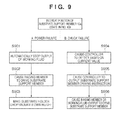
- the drop prevention operation of a vacuum processing apparatus including the drop prevention sensor according to the fourth embodiment will be described with reference to Fig. 9 .
- the controller of the vacuum processing apparatus executes the following processing to cause biasing members 30 of the third embodiment to arrange substrate support members 10a at drop prevention positions (transport positions).
- the output of the working fluid automatically stops (S901).
- the biasing members 30 drive the substrate support members 10a to move them under a substrate holder 3 (S902).
- the substrate holder 3 moves down under its own weight, and the substrate support members 10a receive a substrate 15 (S903).
- the controller of the vacuum processing apparatus executes the following processing. First, the controller detects a chuck failure based on the current value (S904). The controller drives the substrate support members (S905), and arranges them under the substrate holder 3 to receive the substrate 15 (S906). This enables to reliably prevent drop of the substrate 15.
- a pressure sensor for measuring the pressure in the space on the reverse surface side of the substrate 15 may be provided as the drop prevention sensor to detect that the pressure is less than or equal to a predetermined value. That is, if the substrate 15 is not chucked by the electrostatic chuck holder 5, the gas leaks from the space on the reverse surface side so the predetermined pressure cannot be maintained. Hence, the pressure sensor can detect the chuck failure of the substrate 15 by detecting that the pressure is lower than the predetermined pressure.
- the controller of the fourth embodiment When the controller of the fourth embodiment has determined based on the output of the pressure sensor that the pressure is lower than the predetermined threshold (predetermined pressure), the pressure sensor determines that the substrate 15 is not normally chucked by the electrostatic chuck holder 5 so that an instruction to arrange the substrate support members 10a at the drop prevention positions is output to the driving units 10b.
- the controller receives the instruction and executes the processing in steps S904 to S906, thereby preventing drop of the substrate 15 due to a chuck failure or the like during the process.
Landscapes
- Chemical & Material Sciences (AREA)
- Engineering & Computer Science (AREA)
- Organic Chemistry (AREA)
- Materials Engineering (AREA)
- Mechanical Engineering (AREA)
- Metallurgy (AREA)
- Chemical Kinetics & Catalysis (AREA)
- Physics & Mathematics (AREA)
- Plasma & Fusion (AREA)
- Analytical Chemistry (AREA)
- General Chemical & Material Sciences (AREA)
- Container, Conveyance, Adherence, Positioning, Of Wafer (AREA)
- Physical Deposition Of Substances That Are Components Of Semiconductor Devices (AREA)
- Robotics (AREA)
Abstract
A vacuum processing apparatus includes an evacuatable vacuum chamber, a substrate holder which is provided in the vacuum chamber, has a substrate chuck surface vertically facing down, and includes an electrostatic chuck mechanism which electrostatically chucks a substrate, a substrate support member which is provided in the vacuum chamber to keep the substrate parallel to the substrate chuck surface and support the substrate in an orientation that allows the substrate chuck surface to chuck the substrate, and a moving mechanism which moves at least one of the substrate holder and the substrate supported by the substrate support member so as to bring the substrate and the substrate holder into contact with each other, thereby causing the substrate holder to chuck the substrate.
Description
- The present invention relates to a vacuum processing apparatus which improves the quality of a deposited film in the vacuum processing apparatus that chucks a process target using electrostatic chuck, and a vacuum processing method and electronic device manufacturing method using the vacuum processing apparatus.
- A substrate processing apparatus which process a substrate set in a substrate holder while keeping the process surface vertically facing down is called a face-down type vacuum processing apparatus. Since fewer foreign substances (particles) drop on the substrate surface, the face-down type vacuum processing apparatus is more advantageous than a face-up type vacuum processing apparatus which processes a substrate with its process surface vertically facing up.
However, when setting the substrate in the substrate holder, the face-down type vacuum processing apparatus needs to fix the substrate to the substrate set surface of the substrate holder not to allow the substrate to drop due to gravity. - To fix the substrate, a method of clamping the substrate by holding its periphery is used. In another method, an electrode is provided in the substrate holder, and a DC voltage is applied to the electrode so that the substrate set surface electrostatically chucks (ESC) the substrate (for example, PLT1 to PLT3).
- Of the above-described substrate fixing methods, the electrostatic chuck method ensures high substrate temperature controllability as compared to the clamp method. Since there are no shadows of components that hold the substrate periphery for clamping, the process can be performed more uniformly up to the substrate periphery in the vacuum process.
- When the face-down type vacuum processing apparatus processes a substrate, the substrate is conventionally transported to the electrostatic chuck holder in accordance with the following steps (1) to (3).
- (1) A step of placing an unprocessed substrate on the end of the transport arm of a transport robot provided in a transport chamber, transporting the substrate from the transport chamber into a substrate process chamber, and horizontally moving the substrate to a position vertically under the electrostatic chuck holder.
- (2) A step, after step (1), of moving the transport arm or the electrostatic chuck holder vertically downward until the electrostatic chuck holder comes into contact with the substrate.
- (3) A step of causing the electrostatic chuck holder to chuck the substrate by supplying a power for electrostatic chuck.
- However, when the transport arm is extended, it cannot remain level and bends under its own weight due to the moment of inertia that acts in the gravity direction. Hence, the substrate placed on the transport arm and the electrostatic chuck holder cannot maintain the level positional relationship. When making the electrostatic chuck holder chuck the substrate, if the power is supplied to the electrostatic chuck holder that is not horizontally in contact with the substrate (point contact), the electrostatic chuck force does not act on the entire substrate surface, resulting in a chuck error. To prevent the chuck error, the substrate placing portion at the end of the transport arm uses a spring structure.
-
- PLT1: Japanese Patent Laid-Open No.
3-54845 - PLT2: Japanese Patent Laid-Open No.
5-343507 - PLT3: Japanese Patent Laid-Open No.
2001-298072 - However, the complex spring structure used in the substrate placing portion at the end of the transport arm serves as a particle generation source. In addition, if the vacuum processing apparatus is a sputtering deposition apparatus, foreign substances generated from the spring structure adhere to the target surface of the cathode located on the lower side and cause abnormal discharge. The abnormal discharge influences the quality of a film deposited by the vacuum process.
- The present invention has been made in consideration of the above-described problems, and has as its object to provide a vacuum processing apparatus and method capable of suppressing particle generation in a face-down type vacuum processing apparatus and reliably holding and processing a substrate.
- In the present invention, a substrate support member which supports a substrate parallel to a substrate chuck surface is provided in a vacuum chamber independently of a transport robot, thereby reliably maintaining a parallel orientation.
- A vacuum processing apparatus according to an aspect of the present invention is comprising an evacuatable vacuum chamber, a substrate holder which is provided in the vacuum chamber, has a substrate chuck surface vertically facing down, and includes an electrostatic chuck mechanism which electrostatically chucks a substrate, a substrate support member which is provided in the vacuum chamber to keep the substrate parallel to the substrate chuck surface and support the substrate in an orientation that allows the substrate chuck surface to chuck the substrate, and a moving mechanism which moves at least one of the substrate holder and the substrate supported by the substrate support member so as to bring the substrate and the substrate holder into contact with each other, thereby causing the substrate holder to chuck the substrate.
- According to the present invention, it is possible to suppress generation of foreign substances (particles) that drop onto a target and reliably hold a substrate during a process.
- The accompanying drawings, which are incorporated in and constitute a part of the specification, illustrate embodiments of the invention and, together with the description, serve to explain the principles of the invention.
-
Fig. 1 is a view illustrating the arrangement of a vacuum processing apparatus according to the first embodiment; -
Fig. 2 is a view showing an example of an arrangement mainly including asubstrate process chamber 21 provided in the vacuum processing apparatus according to the first embodiment; -
Fig. 3A is a schematic plan view illustrating a shape of asubstrate support member 10a; -
Fig. 3B is a schematic plan view illustrating another shape of thesubstrate support member 10a; -
Fig. 3C is a schematic plan view illustrating still another shape of thesubstrate support member 10a; -
Fig. 4A is a view for explaining a method of loading asubstrate 15; -
Fig. 4B is a view for explaining the method of loading thesubstrate 15; -
Fig. 4C is a view for explaining the method of loading thesubstrate 15; -
Fig. 4D is a view for explaining the method of loading thesubstrate 15; -
Fig. 4E is a view for explaining the method of loading thesubstrate 15; -
Fig. 4F is a view for explaining the method of loading thesubstrate 15; -
Fig. 4G is a view for explaining the method of loading thesubstrate 15; -
Fig. 5 is a graph showing the effect obtained by using the vacuum processing apparatus according to the first embodiment and that obtained by using a conventional apparatus; -
Fig. 6 is a flowchart illustrating the operation of the controller of a vacuum processing apparatus according to the second embodiment; -
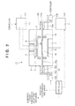
Fig. 7 is a view illustrating the arrangement of a vacuum processing apparatus according to the third embodiment; -
Fig. 8 is a view showing the drop prevention operation of the vacuum processing apparatus according to the third embodiment; and -
Fig. 9 is a flowchart for explaining the drop prevention operation of a vacuum processing apparatus according to the fourth embodiment. - Preferred embodiments of the present invention will now be described in detail. Note that the constituent elements described in the embodiments are merely examples. The technical scope of the present invention is determined by the scope of claims and is not limited by the following individual embodiments.
- A vacuum processing apparatus 1 according to the embodiment of the present invention is comprising a
vacuum chamber 2, asubstrate holder 3, asubstrate support member 10a, and a moving mechanism which causes thesubstrate holder 3 to chuck asubstrate 15. - In the vacuum processing apparatus 1 according to the embodiment of the present invention, the
vacuum chamber 2 is an evacuatable chamber. - In the vacuum processing apparatus 1 according to the embodiment of the present invention, the
substrate holder 3 is provided in thevacuum chamber 2, has a substrate chuck surface 5a vertically facing down, and includes an electrostatic chuck mechanism which electrostatically chucks thesubstrate 15. - In the vacuum processing apparatus 1 according to the embodiment of the present invention, the
substrate support members 10a are provided in thevacuum chamber 2, and support thesubstrate 15 in such an orientation that allows the substrate chuck surface 5a to chuck the substrate while keeping thesubstrate 15 and the substrate chuck surface 5a of thesubstrate holder 3 parallel. - In the vacuum processing apparatus 1 according to the embodiment of the present invention, the moving mechanism functions as a means for moving at least one of the
substrate holder 3 and thesubstrate 15 supported by thesubstrate support members 10a so as to bring them into contact with each other, thereby causing thesubstrate holder 3 to chuck thesubstrate 15. - Embodiments of the vacuum processing apparatus 1 according to the present invention and a vacuum processing method using the same will be described below in detail with reference to the accompanying drawings.
-
Fig. 1 is a schematic view showing the arrangement of a vacuum processing apparatus 1 according to the first embodiment of the present invention. As shown inFig. 1 , the vacuum processing apparatus 1 of this embodiment is formed by connecting a plurality of evacuatable chambers (vacuum chambers) connected to an evacuation system (not shown) to anevacuatable transport chamber 22 viagate valves 23. Examples of the chambers connected to thetransport chamber 22 are aload lock chamber 24 which introduces asubstrate 15 into the vacuum processing apparatus 1, asubstrate process chamber 21 which vacuum-processes thesubstrate 15, and an unloadlock chamber 25 which recovers the processedsubstrate 15. The vacuum processing apparatus 1 shown inFig. 1 includes foursubstrate process chambers 21, oneload lock chamber 24, and one unloadlock chamber 25. However, the embodiment of the present invention is not limited to this. - The
transport chamber 22 includes atransport robot 14 serving as a substrate transport mechanism so as to be able to transport thesubstrate 15 to each chamber. -
Fig. 2 is a schematic view showing an arrangement mainly including thesubstrate process chamber 21 provided in the vacuum processing apparatus 1 inFig. 1 . - In the arrangement shown in
Fig. 2 , asubstrate holder 3 has anelectrostatic chuck holder 5. In this embodiment, the lower surface (substrate chuck surface 5a) of theelectrostatic chuck holder 5 in the vertical direction is parallel to the surface of thesubstrate 15. - The
electrostatic chuck holder 5 is made of a dielectric material, and incorporates a plurality of (in this embodiment, two)electrostatic chuck electrodes electrostatic chuck electrodes DC power supply 12 to apply voltages to theelectrostatic chuck electrodes - The
substrate holder 3 is connected to a vertically drivable moving mechanism (not shown) so as to be movable in the vertical direction. - A
target 8 is located on the lower side inside thevacuum chamber 2, and arranged to parallelly face theelectrostatic chuck holder 5 of thesubstrate holder 3 above. - A
DC power supply 11 is connected to thetarget 8. TheDC power supply 11 applies a predetermined voltage to thetarget 8. That is, thetarget 8 constitutes a cathode portion. Note that the power supply connected to thetarget 8 is not limited to the DC power supply. For example, it may be an RF power supply with a frequency of, for example, 13.56 MHz. - A
magnet unit 9 is arranged on the rear side of thetarget 8. Themagnet unit 9 forms a specific magnetic field distribution on the surface of thetarget 8. - Note that the
magnet unit 9 uses an electromagnet, permanent magnet, or the like. A plurality of kinds of magnets may be combined. - When performing sputtering deposition using the
target 8, theDC power supply 12 and themagnet unit 9 hold thenecessary target 8 at a predetermined voltage to form a predetermined magnetic field distribution on the surface of thetarget 8. This allows sputtering by discharge at a low pressure. - A
shield 13 is provided in thesubstrate process chamber 21. Theshield 13 is provided to prevent a film from sticking to the inner wall of thesubstrate process chamber 21 during deposition by sputtering on thesubstrate 15 held by thesubstrate holder 3. In this embodiment, theshield 13 has a shape (for example, almost cylindrical shape) that surrounds the discharge space between thesubstrate holder 3 and thetarget 8. Theshield 13 has an opening portion (not shown) to transport thesubstrate 15 into the discharge space. -
Substrate support mechanisms 10 exist between thesubstrate holder 3 and thetarget 8. Thesubstrate support mechanisms 10 include thesubstrate support members 10a on which thesubstrate 15 can be placed, and have a structure for supporting thesubstrate 15 in such an orientation that allows the substrate chuck surface 5a to chuck thesubstrate 15. More specifically, the substrate support mechanisms have a structure capable of horizontally supporting thesubstrate 15 with respect to the substrate chuck surface 5a, as shown inFig. 2 . In this embodiment, the substrate support mechanisms levelly hold thesubstrate 15 placed on them. Eachsubstrate support mechanism 10 also includes adriving unit 10b such as an air cylinder (not shown) provided outside thesubstrate process chamber 21. The drivingunit 10b can move thesubstrate support member 10a out of theshield 13. Note that inFig. 2 , aguide member 10e is fixed to thesubstrate process chamber 21 to guide thesubstrate support member 10a such that it can horizontally move.Bellows 10d maintain the vacuum state of thesubstrate process chamber 21. -
Figs. 3A to 3C are plan views showing the shapes of thesubstrate support members 10a. - In this embodiment, as shown in
Fig. 2 , a pair ofsubstrate support mechanisms 10 are provided on both sides of the discharge space. Hence, as shown inFig. 3A , thesubstrate support member 10a of eachsubstrate support mechanism 10 has a shape capable of coming into contact with thesubstrate 15 at at least two separate points. Eachsubstrate support member 10a includesconvex contact portions 10c to equalize the support heights at the contact positions. Eachsubstrate support member 10a is made of a material such as SUS or an aluminum alloy, and designed to be so rigid as to prevent each end from bending under its own weight.
Thecontact portions 10c can be made of SUS. However, they may be made of a ceramic such as quartz or alumina. Using quartz or alumina allows to suppress the influence of contamination on thesubstrate 15. - Note that as shown in
Fig. 3B , the substrate support member may be provided on only one side. That is, one substrate support member may suffice. Thecontact portions 10c are preferably provided to allow onesubstrate support member 10a to support the substrate at at least three separate points. Alternatively, three or moresubstrate support members 10a may be arranged. For example, threesubstrate support members 10a may be arranged, as shown inFig. 3C . In this case, eachsubstrate support member 10a has at least onecontact portion 10c. If thesubstrate support member 10a is long, it bends not a little under its own weight even if the design ensures the rigidity. Considering this, arranging a plurality of substrate support members symmetrically about the substrate center, as shown inFig. 3A or 3C allows to equalize the bending amounts of thesubstrate support members 10a and horizontally support thesubstrate 15. - A process of transporting the
substrate 15 will be described next. -
Figs. 4A to 4G are views for explaining a method of loading thesubstrate 15. Note that thesubstrate support mechanisms 10 and the moving mechanism (not shown) of thesubstrate holder 3 shown inFig. 4A , and the ESCDC power supply 12 and thepower supply 11 shown inFig. 2 are controlled based on signals from the controller. Loading of thesubstrate 15 is controlled by executing a program in the controller. Note that the controller is formed from, for example, a general computer. - The method of loading the
substrate 15 will be described with a focus placed on control of the controller. - As shown in
Fig. 4A , thesubstrate 15 is placed on anend effector 14a of thetransport robot 14 and moved to a position vertically under thesubstrate holder 3. - The
end effector 14a is moved downward to place thesubstrate 15 on thesubstrate support members 10a, as shown inFig. 4B . - After that, the
end effector 14a retreats from thesubstrate process chamber 21, as shown inFig. 4C . - The
substrate holder 3 is moved vertically downward from above thesubstrate 15 up to a position immediately before theelectrostatic chuck holder 5 of thesubstrate holder 3 comes into contact with thesubstrate 15, as shown inFig. 4D . - The
substrate holder 3 is further moved vertically downward from above thesubstrate 15 up to a position where theelectrostatic chuck holder 5 comes into contact with thesubstrate 15, as shown inFig. 4E . - Voltages are applied to the
electrostatic chuck electrodes electrostatic chuck holder 5 of thesubstrate holder 3 thus chucks thesubstrate 15. - The
substrate holder 3 is lifted and moved to a predetermined process position, as shown inFig. 4F . - The
substrate support members 10a inside thesubstrate process chamber 21 move out of theshield 13. At this time, the drivingunits 10b included in the moving mechanisms cause thesubstrate support members 10a shown inFig. 2 to retreat to positions (the retreat positions of thesubstrate support members 10a) where the sputtering substance from thetarget 8 does not stick, as shown inFig. 4G . - Next, the
magnet unit 9 forms a predetermined magnetic field distribution on the surface of thetarget 8, and theDC power supply 11 applies a negative DC voltage to thetarget 8. This causes discharge at a low pressure so that thetarget 8 takes positive ions in the discharge plasma through its surface and liberates sputtering particles. The sputtering particles stick to thesubstrate 15 so that a sputtering deposition process is performed. The sputtering particles, which scatter not only toward thesubstrate 15 but also in all directions, are blocked by theshield 13 so they rarely scatter out of it. Hence, the sputtering particles are rarely deposited inside thesubstrate process chamber 21. - Note that during the deposition process after the start of discharge, the discharge pressure may be adjusted as needed while supplying a gas from a gas supply system (not shown).
- After the end of deposition process, the
substrate 15 is unloaded in an order opposite to that of loading. - More specifically, the
substrate support members 10a that have moved out of theshield 13 move into theshield 13, and stop at a position vertically under thesubstrate 15 chucked by theelectrostatic chuck holder 5 of the substrate holder 3 (Fig. 4F ). - After that, the
substrate holder 3 vertically moves downward up to a position where thesubstrate 15 chucked by theelectrostatic chuck holder 5 comes into contact with thesubstrate support members 10a (Fig. 4E ). - Then, voltage application to the
electrostatic chuck electrodes substrate 15 has moved onto thesubstrate support members 10a under its own weight (Fig. 4D ), thesubstrate holder 3 vertically moves upward (Fig. 4C ). - Finally, the
end effector 14a moves thesubstrate 15 out of the substrate process chamber 21 (Figs. 4B and 4A ). -
Fig. 5 is a graph showing the effect obtained by using the vacuum processing apparatus 1 according to the first embodiment of the present invention and that obtained by using a conventional apparatus. The abscissa of the graph inFig. 5 represents the number of continuously processed substrates, and the ordinate represents the number of times of abnormal discharge per substrate observed during the substrate process. Note that the number of times of abnormal discharge is already known to be proportional to the number of foreign substances (particles) that drop from above the target and stick to the target. The abnormal discharge was determined by monitoring the voltage and current of the DC power supply for discharge. - As can be confirmed from the graph of
Fig. 5 , according to the vacuum processing apparatus 1 of the present invention, the frequency of abnormal discharge caused by the foreign substances (particles) that drop and stick to thetarget 8 greatly decreases. - If the substrate process temperature in the sputtering process needs to be high, a
substrate holder 3 may include a temperature adjustment mechanism. The temperature adjustment mechanism adjusts the temperature of a substrate chuck surface 5a shown inFig. 2 . The temperature adjustment mechanism is, for example, a heater incorporated in thesubstrate holder 3 or a mechanism for circulating a liquid heat transport medium to thesubstrate holder 3. Note that the heater and the heat transport medium circulating mechanism may be used together to increase the temperature controllability of thesubstrate holder 3. - When the substrate process temperature needs to be high, it is preferable to cause the temperature adjustment mechanism to heat the
substrate holder 3, and thus heat aprocess target substrate 15 by the radiant heat from thesubstrate holder 3. - The
substrate 15 transported from the outside of asubstrate process chamber 21 is cooler than thesubstrate holder 3. - If the
substrate 15 cooler than thesubstrate holder 3 heated in advance is set on thesubstrate holder 3 and electrostatically chucked, thesubstrate 15 expands as its temperature rises. Since the suction force acts between thesubstrate holder 3 and thesubstrate 15 at this time, the surface of thesubstrate holder 3 may rub against the surface of thesubstrate 15, and foreign substances (particles) may be generated from one or both of the surface of thesubstrate holder 3 and that of thesubstrate 15. - For this reason, if the substrate process temperature needs to be raised, it is preferable to maintain the positional relationship between the
substrate holder 3 and thesubstrate 15 moved to near thesubstrate holder 3 and heat thesubstrate 15 in advance up to the same temperature as that of thesubstrate holder 3 by the radiant heat from thesubstrate holder 3. - Transport of the
substrate 15 according to this embodiment will be described with reference to the accompanying drawings.Fig. 6 is a flowchart illustrating control of a controller according to the second embodiment. The positional relationship of thesubstrate holder 3 andsubstrate support mechanisms 10 is the same as that shown inFigs. 4A to 4G . - First, in step S101, the controller operates the temperature adjustment mechanism of the
substrate holder 3 to adjust the chuck surface for thesubstrate 15 to a desired temperature. In step S102, thesubstrate 15 is placed on anend effector 14a of atransport robot 14 and moved to a position vertically under the substrate holder 3 (Fig. 4A ). - In step S103, the
end effector 14a is moved downward to place thesubstrate 15 onsubstrate support members 10a (Fig. 4B ). - After that, in step S104, the
end effector 14a retreats from a substrate process chamber 21 (Fig. 4C ). - In step S105, the
substrate holder 3 is moved vertically downward from above thesubstrate 15 up to a position immediately before anelectrostatic chuck holder 5 of thesubstrate holder 3 comes into contact with thesubstrate 15, as shown inFig. 4D . - In this state, the process waits until a predetermined time has elapsed (step S106). During this time, the
substrate 15 is heated using the radiant heat from the surface of theelectrostatic chuck holder 5. Thesubstrate 15 expands as its temperature rises in heating. However, when the rise of the substrate temperature is saturated, the expansion of thesubstrate 15 converges. The predetermined time in step S106 is set as follows. For example, the temperature adjustment mechanism of thesubstrate holder 3 heats the chuck surface 5a to a predetermined temperature, thesubstrate holder 3 is moved close to thesubstrate 15, and the time until the substrate temperature is saturated is obtained in advance. This time is set as the predetermined time. - After the elapse of the predetermined time (YES in step S106), in step S107, the
substrate holder 3 is further moved vertically downward from above thesubstrate 15 up to a position where thesubstrate holder 3 comes into contact with thesubstrate 15 whose thermal expansion has converged, as shown inFig. 4E . In step S108, voltages are applied toelectrostatic chuck electrodes electrostatic chuck holder 5 of thesubstrate holder 3 thus chucks thesubstrate 15. Note that instead of determining the elapse of the predetermined time, a temperature sensor such as a thermistor may be provided inside thesubstrate holder 3 or in the interface between theelectrostatic chuck holder 5 and thesubstrate holder 3. Data detected by the temperature sensor may be input to the controller to determine, based on the data, the timing to bring thesubstrate holder 3 into contact with thesubstrate 15. As for the criterion to determine the timing, for example, whether the temperature changes of theelectrostatic chuck holder 5 and thesubstrate 15 are saturated, or whether thesubstrate 15 has reached a predetermined saturation temperature can be determined. Alternatively, it may be determined whether thesubstrate 15 has reached a predetermined temperature.
A plurality of temperature sensors may be provided to determine whether the temperature difference at each portion is saturated. - The subsequent steps are the same as in the above-described first embodiment. More specifically, in step S109, the
substrate holder 3 is lifted and moved to a predetermined process position, as shown inFig. 4F . Then, in step S110, thesubstrate support members 10a move outside of ashield 13, and to the outside of thesubstrate process chamber 21. Thesubstrate support members 10a retreat to positions where the sputtering substance from atarget 8 does not stick, as shown inFig. 4G , and the deposition process starts. - Even when the substrate is heated to a high temperature, substrate transport according to the above-described procedure makes it possible to perform high-quality deposition in the vacuum processing apparatus further including the temperature adjustment mechanism.
- The
substrate 15 is heated while maintaining the state in which thesubstrate 15 is located near thesubstrate holder 3. At this time, if the substrate that remains on theend effector 14a is directly heated without using thesubstrate support members 10a, theend effector 14a is also heated. If theend effector 14a is heated, the heat is transported to the robot so as to heat the driving system of the robot. This may make the robot halt or malfunction. Using the vacuum processing apparatus 1 according to the embodiment of the present invention allows to shorten the time thetransport robot 14a is located under thesubstrate holder 3 and also prevent theend effector 14a from being heated. It is therefore possible to suppress the above-described malfunction and the like of the robot. - If the
substrate 15 kept placed on theend effector 14a is heated, thesubstrate 15 cannot be transported during that time. This lowers throughput in the vacuum processing apparatus having a plurality of chambers. Performing the vacuum process using thesubstrate support members 10a, as in the vacuum processing apparatus 1 of the present invention, solves the problem of throughput. - In the above-described first and second embodiments, a sputtering apparatus having a target has been explained. However, the application of the present invention is not limited to this. More specifically, the present invention is suitably applicable to any apparatus other than the sputtering apparatus, such as a PVD (Physical Vapor Deposition) apparatus, CVD apparatus, ALD apparatus, or dry etching apparatus, if it processes the
substrate 15 fixed to the substrate holder by electrostatic chuck while making its process surface vertically face down. - The present invention is applicable to, for example, the manufacture of the following electronic devices. Sputtering deposition using a ceramic target readily produces powder deposits on members other than the substrate. The powder deposits have weak adhesion and therefore easily change to particles. Examples are ITO (Indium Tin Oxide) used in an LCD and PZT (Lead Zirconate Titanate) used in a piezoelectric element or a ferroelectric memory. When forming such a film, the face-down type apparatus is effective to suppress particle mixing into the film on the substrate. When forming a GaN film for an LED or a power device by MBE or sputtering using a Ga metal as a source, the face-down type apparatus needs to be used because the melting point of the Ga metal is as low as 29.8°C. The fundamental of the present invention is a face-down type vacuum processing apparatus capable of suppressing article mixing onto a substrate. Hence, the present invention is suitable adaptive to any processing apparatus and electronic device manufacture which suffer a similar problem of particle mixing onto a substrate.
- The
substrate support mechanisms 10 need not always horizontally move thesubstrate support members 10a. For example, thesubstrate support mechanisms 10 may move thesubstrate support members 10a upward at the time of chucking and make them retreat downward during the vacuum process. Alternatively, thesubstrate support mechanisms 10 may move thesubstrate support members 10a horizontally and vertically. The substrate support mechanisms preferably move thesubstrate support members 10a only in a direction parallel to the substrate chuck surface 5a of theelectrostatic chuck holder 5, as in this embodiment. Thesubstrate support mechanisms 10 can have a simple structure, and be installed without impeding the process of thesubstrate 15. It is therefore possible to suppress an increase in particles caused by a complex structure or an increase in particles caused by a larger opening diameter of theshield 13. - Making the
substrate support members 10a retreat from the position vertically under thesubstrate holder 3 is not essential in the present invention. However, it is preferable because retreating at the time of the substrate process allows to prevent process substances from sticking and suppress contamination and an increase in particles. - In the above embodiments, the
shield 13 has such a shape that surrounds the substrate process space However, it may have a shape that surrounds thesubstrate support members 10a that have retreated. - If at least the substrate supporting portion of each
substrate support member 10a is arranged in the vacuum process chamber, the proximal end of thesubstrate support member 10a may extend out of thevacuum chamber 2. - In the above-described first and second embodiments, the substrate chuck surface 5a vertically facing down has been explained. However, the gist of the present invention is not limited to this example. For example, the substrate chuck surface 5a may tilt as far as the
substrate support members 10a supports thesubstrate 15 horizontally with respect to the substrate chuck surface 5a. - The third embodiment will be described next with reference to the schematic view of
Fig. 7 . Note that the same reference numerals as in the first embodiment denote the common apparatus components in the third embodiment, and a description thereof will not be repeated. - A vacuum processing apparatus 1 according to the third embodiment is different from that of the first embodiment in that
substrate support members 10a are arranged under asubstrate holder 3 when the substrate holding force (the force to hold a substrate) falls below the force (substrate load) necessary for holding a substrate (for example, in case of a power failure) during the process. More specifically, the apparatus includes biasingmembers 30 which continuously bias, toward the transport positions under thesubstrate holder 3, thesubstrate support members 10a that are located at the retreat positions. When the operation of drivingunits 10b has stopped due to a power failure or the like, the biasing force of the biasingmembers 30 moves thesubstrate support members 10a to the transport positions. Each biasingmember 30 is designed as a cylinder which moves the correspondingsubstrate support member 10a in the translating direction (from the retreat position to the transport position or from the transport position to the retreat position) by, for example, the elastic force of an elastic body (e.g., spring or fluid). - On the other hand, the driving
units 10b of thesubstrate support members 10a can directly use the biasing force to drive thesubstrate support members 10a to the transport positions. The drivingunits 10b can also generate an additional driving force to drive thesubstrate support members 10a and move thesubstrate support members 10a to the transport positions. Thesubstrate support members 10a are driven to the retreat positions by generating driving forces equal to or more than the biasing forces in directions opposite to those of the biasing forces. For example, when each drivingunit 10b is formed from an air cylinder or a hydraulic cylinder, it may be either a single acting cylinder for generating only a driving force toward the retreat position or a double acting cylinder capable of generating driving forces toward both the retreat position and the transport position. - Note that in the third embodiment, the biasing
member 30 and thedriving unit 10b are formed as separate members. However, the biasingmember 30 and thedriving unit 10b may be integrated. For example, they may be formed as a single acting cylinder whose home position (normal position) is the transport position. - Additionally, in the third embodiment, a moving
mechanism 33 of thesubstrate holder 3 includes a single acting cylinder whose normal position is the transport position so as to move thesubstrate holder 3 vertically based on an instruction from a controller. - The operation of the vacuum processing apparatus 1 having the above-described arrangement will be described with reference to
Fig. 8 . Reference numeral 8a inFig. 8 indicates a state of the vacuum processing apparatus 1 during the process. Assume that power supply toelectrostatic chuck electrodes substrate holder 3 holds asubstrate 15 for a while by residual charges. Then, the holding force is lost, and thesubstrate 15 drops under its own weight. - At this time, driving force supply from the driving source also stops, and the
substrate support members 10a are driven to the transport positions by the biasing forces of the biasingmembers 30. Similarly, driving force supply to the movingmechanism 33 of thesubstrate holder 3 also stops, and thesubstrate holder 3 moves downward to the transport position by its load. - In this case, even when the
substrate 15 drops, thesubstrate support members 10a can receive it, as indicated by 8b inFig. 6 , thereby preventing damage to thesubstrate 15 and the target. In the third embodiment, since thesubstrate holder 3 moves down simultaneously, the drop distance can be shorter. It is therefore possible to reliably prevent drop of the substrate. - As described above, when the substrate holding force falls below the force (substrate load) necessary for holding a substrate during the process, the
substrate support members 10a move into asubstrate process chamber 21 so as to function as a mechanism for preventing substrate drop. This allows to solve the problem of substrate drop unique to the face-down type apparatus. In case of substrate drop, it is necessary to exchange the target that has received the dropped substrate and remove the substrate fragments by stopping the line and exposing the interior of thesubstrate process chamber 21 to the atmosphere. The cost for line stop and recovery is enormous. Providing another substrate drop prevention mechanism is also considerable. However, it is difficult to provide a structure for drop prevention in the deposition space without influencing the deposition process. In addition, the structure can be a contamination source. From this viewpoint, forming a substrate drop prevention mechanism by thesubstrate support members 10a, as in the present invention, allows to effectively prevent substrate drop without posing a problem of contamination or the like. - A drop prevention sensor for detecting a substrate chuck failure may be added to the vacuum processing apparatus of the third embodiment so as to detect that the substrate holding force is lower than the substrate load. The drop prevention operation of a vacuum processing apparatus including the drop prevention sensor according to the fourth embodiment will be described with reference to
Fig. 9 . As shown inFig. 9 , in case of a power failure (A inFig. 9 ), the controller of the vacuum processing apparatus executes the following processing to cause biasingmembers 30 of the third embodiment to arrangesubstrate support members 10a at drop prevention positions (transport positions). First, when a power failure has occurred, the output of the working fluid automatically stops (S901). The biasingmembers 30 drive thesubstrate support members 10a to move them under a substrate holder 3 (S902). Thesubstrate holder 3 moves down under its own weight, and thesubstrate support members 10a receive a substrate 15 (S903). - If the electrostatic chuck force falls below the substrate holding force without a power failure (B in
Fig. 9 ), the biasingmembers 30 or drivingunits 10b actively arrange thesubstrate support member 10a at the drop prevention positions. The controller of the vacuum processing apparatus executes the following processing. First, the controller detects a chuck failure based on the current value (S904). The controller drives the substrate support members (S905), and arranges them under thesubstrate holder 3 to receive the substrate 15 (S906). This enables to reliably prevent drop of thesubstrate 15. - For example, when flowing a gas for heat transmission to the reverse surface side of the
substrate 15 chucked by anelectrostatic chuck holder 5, a pressure sensor for measuring the pressure in the space on the reverse surface side of thesubstrate 15 may be provided as the drop prevention sensor to detect that the pressure is less than or equal to a predetermined value. That is, if thesubstrate 15 is not chucked by theelectrostatic chuck holder 5, the gas leaks from the space on the reverse surface side so the predetermined pressure cannot be maintained.
Hence, the pressure sensor can detect the chuck failure of thesubstrate 15 by detecting that the pressure is lower than the predetermined pressure. When the controller of the fourth embodiment has determined based on the output of the pressure sensor that the pressure is lower than the predetermined threshold (predetermined pressure), the pressure sensor determines that thesubstrate 15 is not normally chucked by theelectrostatic chuck holder 5 so that an instruction to arrange thesubstrate support members 10a at the drop prevention positions is output to the drivingunits 10b. The controller receives the instruction and executes the processing in steps S904 to S906, thereby preventing drop of thesubstrate 15 due to a chuck failure or the like during the process. - The preferred embodiments of the present invention have been described above with reference to the accompanying drawings. However, the present invention is not limited to the above embodiments, and various changes and modifications can be made within the technical scope determined by the scope of claims.
- This application claims the benefit of Japanese Patent Application No.
2008-161477, filed on June 20, 2008
Claims (9)
- A vacuum processing apparatus comprising:an evacuatable vacuum chamber;a substrate holder which is provided in said vacuum chamber, has a substrate chuck surface vertically facing down, and includes an electrostatic chuck mechanism which electrostatically chucks a substrate;a substrate support member which is provided in said vacuum chamber to support the substrate in an orientation that allows the substrate chuck surface to chuck the substrate; andmoving means for moving at least one of said substrate holder and the substrate supported by said substrate support member so as to bring the substrate and said substrate holder into contact with each other, thereby causing said substrate holder to chuck the substrate.
- The vacuum processing apparatus according to claim 1, further comprising substrate support member driving means for, after the substrate is chucked, causing the substrate support member to retreat from a position where the substrate is chucked.
- The vacuum processing apparatus according to claim 1 or 2, further comprising a shield which separates said substrate holder and a retreat position of said substrate support member from each other.
- The vacuum processing apparatus according to any one of claims 1 to 3, wherein said substrate support member supports the substrate in parallel to said substrate holder.
- The vacuum processing apparatus according to any one of claims 1 to 4, further comprising:a temperature adjustment mechanism incorporated in said substrate holder; anda controller,wherein said temperature adjustment mechanism adjusts a temperature of the substrate chuck surface, andsaid controller controls said electrostatic chuck mechanism, said temperature adjustment mechanism, and said moving means so as to bring said substrate holder and the substrate supported by said substrate support member close to each other while operating said temperature adjustment mechanism, make an operation of said electrostatic chuck mechanism wait until a predetermined time has elapsed while keeping the substrate and said substrate holder close to each other, and operate said electrostatic chuck mechanism after the elapse of the predetermined time while keeping the substrate in contact with the substrate chuck surface.
- The vacuum processing apparatus according to any one of claims 1 to 5, wherein if a substrate holding force to hold the substrate lowers during a process of electrostatic chuck, said substrate support member is arranged at a position under said substrate holder.
- The vacuum processing apparatus according to claim 6, further comprising a biasing member which continuously biases said substrate support member located at the retreat position toward the position under said substrate holder,
wherein if the substrate holding force lowers during the process, said substrate support member is moved to the position under said substrate holder by a biasing force of said biasing member. - A vacuum processing method of performing a vacuum process using a substrate holder while keeping the substrate holder electrostatically chucking a substrate, the substrate holder being provided in an evacuatable vacuum chamber, having a substrate chuck surface, and including an electrostatic chuck mechanism which electrostatically chucks the substrate, comprising the steps of:causing a substrate transport mechanism to transport the substrate into the vacuum chamber;transferring the substrate to a substrate support member which supports the substrate in an orientation that allows the substrate chuck surface to chuck the substrate;bringing the substrate and the substrate chuck surface into contact with each other while keeping the substrate support member supporting the substrate; andoperating the electrostatic chuck mechanism to electrostatically chuck the substrate while keeping the substrate and the substrate chuck surface in contact with each other.
- An electronic device manufacturing method using a vacuum processing apparatus for performing a vacuum process while keeping a substrate holder electrostatically chucking a substrate, the substrate holder being provided in an evacuatable vacuum chamber, having a substrate chuck surface vertically facing down, and including an electrostatic chuck mechanism which electrostatically chucks the substrate, comprising the steps of:causing a substrate transport mechanism to transport the substrate into the vacuum chamber;transferring the substrate to a substrate support member which supports the substrate in an orientation that allows the substrate chuck surface to chuck the substrate;bringing the substrate and the substrate chuck surface into contact with each other while keeping the substrate support member supporting the substrate;operating the electrostatic chuck mechanism to electrostatically chuck the substrate while keeping the substrate and the substrate chuck surface in contact with each other; andperforming the vacuum process for the electrostatically chucked substrate.
Applications Claiming Priority (2)
| Application Number | Priority Date | Filing Date | Title |
|---|---|---|---|
| JP2008161477 | 2008-06-20 | ||
| PCT/JP2009/002802 WO2009154002A1 (en) | 2008-06-20 | 2009-06-19 | Vacuum processing apparatus, vacuum processing method, and manufacturing method of an electronic device |
Publications (1)
| Publication Number | Publication Date |
|---|---|
| EP2290678A1 true EP2290678A1 (en) | 2011-03-02 |
Family
ID=41433920
Family Applications (1)
| Application Number | Title | Priority Date | Filing Date |
|---|---|---|---|
| EP09766450A Withdrawn EP2290678A1 (en) | 2008-06-20 | 2009-06-19 | Vacuum processing apparatus, vacuum processing method, and electronic device manufacturing method |
Country Status (5)
| Country | Link |
|---|---|
| US (2) | US20110064880A1 (en) |
| EP (1) | EP2290678A1 (en) |
| JP (1) | JP4603099B2 (en) |
| CN (1) | CN102047406B (en) |
| WO (1) | WO2009154002A1 (en) |
Families Citing this family (9)
| Publication number | Priority date | Publication date | Assignee | Title |
|---|---|---|---|---|
| KR101564251B1 (en) | 2010-12-27 | 2015-10-29 | 캐논 아네르바 가부시키가이샤 | Epitaxial film forming method, sputtering apparatus, manufacturing method of semiconductor light-emitting element, semiconductor light-emitting element, and illumination device |
| WO2014002465A1 (en) * | 2012-06-26 | 2014-01-03 | キヤノンアネルバ株式会社 | Epitaxial film-forming method, sputtering device, method for manufacturing semiconductor light-emitting element, semiconductor light-emitting element, and illumination device |
| US9929121B2 (en) * | 2015-08-31 | 2018-03-27 | Kulicke And Soffa Industries, Inc. | Bonding machines for bonding semiconductor elements, methods of operating bonding machines, and techniques for improving UPH on such bonding machines |
| KR102790445B1 (en) * | 2016-11-25 | 2025-04-01 | 이윤택 | System for Manufacturing ultra-light high strength automotive parts including Graphene |
| US11011397B2 (en) * | 2018-12-20 | 2021-05-18 | Axcelis Technologies, Inc. | Wafer soak temperature readback and control via thermocouple embedded end effector for semiconductor processing equipment |
| TWI896881B (en) * | 2022-06-08 | 2025-09-11 | 凌嘉科技股份有限公司 | Parallel film coating equipment and multi-layer film coating method |
| WO2025075878A1 (en) * | 2023-10-04 | 2025-04-10 | Applied Materials, Inc. | High speed injection nozzle for pre-polish modification of substrate thickness |
| CN117901432B (en) * | 2024-03-19 | 2024-07-05 | 成都骏创科技有限公司 | Electrostatic chuck system capable of monitoring laminating pressure and flatness in real time |
| CN118501196B (en) * | 2024-04-11 | 2025-05-23 | 深圳市埃芯半导体科技有限公司 | Positioning chuck and semiconductor wafer analysis device |
Family Cites Families (17)
| Publication number | Priority date | Publication date | Assignee | Title |
|---|---|---|---|---|
| JPS6132504A (en) | 1984-07-25 | 1986-02-15 | Sumitomo Metal Mining Co Ltd | Vertically magnetized magnetic thin film |
| JP2510290B2 (en) | 1989-07-24 | 1996-06-26 | 富士電機株式会社 | How to remove the object to be processed from the electrostatic chuck |
| JP2550787B2 (en) * | 1991-03-12 | 1996-11-06 | 富士通株式会社 | Semiconductor device manufacturing equipment |
| JPH05343507A (en) | 1992-06-10 | 1993-12-24 | Fujitsu Ltd | Electrostatic adsorption method |
| JPH0688221A (en) * | 1992-09-07 | 1994-03-29 | Fuji Electric Co Ltd | Sputtering device |
| JP3045443B2 (en) * | 1993-10-20 | 2000-05-29 | 東京エレクトロン株式会社 | Plasma processing equipment |
| KR100276736B1 (en) * | 1993-10-20 | 2001-03-02 | 히가시 데쓰로 | Plasma processing equipment |
| JPH0860355A (en) * | 1994-08-23 | 1996-03-05 | Tel Varian Ltd | Treating device |
| US5820329A (en) * | 1997-04-10 | 1998-10-13 | Tokyo Electron Limited | Vacuum processing apparatus with low particle generating wafer clamp |
| JP4282848B2 (en) * | 1999-06-04 | 2009-06-24 | 旭化成ケミカルズ株式会社 | Inorganic particle dispersion composition |
| JP4489904B2 (en) * | 2000-04-14 | 2010-06-23 | 株式会社アルバック | Vacuum processing apparatus and substrate holding method |
| KR100469359B1 (en) * | 2002-02-20 | 2005-02-02 | 엘지.필립스 엘시디 주식회사 | bonding device for liquid crystal display |
| KR100469360B1 (en) * | 2002-02-22 | 2005-02-02 | 엘지.필립스 엘시디 주식회사 | bonding device for liquid crystal display and operation method thereof |
| US7270587B2 (en) * | 2002-03-05 | 2007-09-18 | Lg.Philips Lcd Co., Ltd. | Apparatus and method for manufacturing liquid crystal display devices, method for using the apparatus, and device produced by the method |
| JP3823083B2 (en) * | 2002-07-19 | 2006-09-20 | 株式会社 日立インダストリイズ | Board assembly equipment |
| JP4513533B2 (en) * | 2004-12-01 | 2010-07-28 | 株式会社ニコン | Substrate drop prevention device and exposure apparatus |
| JP4828401B2 (en) | 2006-12-28 | 2011-11-30 | 株式会社ソフイア | Game machine |
-
2009
- 2009-06-19 WO PCT/JP2009/002802 patent/WO2009154002A1/en not_active Ceased
- 2009-06-19 EP EP09766450A patent/EP2290678A1/en not_active Withdrawn
- 2009-06-19 CN CN200980119910.9A patent/CN102047406B/en active Active
- 2009-06-19 JP JP2010517738A patent/JP4603099B2/en active Active
-
2010
- 2010-11-23 US US12/952,814 patent/US20110064880A1/en not_active Abandoned
-
2012
- 2012-10-10 US US13/648,669 patent/US8709218B2/en active Active
Non-Patent Citations (1)
| Title |
|---|
| See references of WO2009154002A1 * |
Also Published As
| Publication number | Publication date |
|---|---|
| CN102047406A (en) | 2011-05-04 |
| JP4603099B2 (en) | 2010-12-22 |
| US8709218B2 (en) | 2014-04-29 |
| US20130032468A1 (en) | 2013-02-07 |
| WO2009154002A1 (en) | 2009-12-23 |
| JPWO2009154002A1 (en) | 2011-11-24 |
| CN102047406B (en) | 2013-06-05 |
| US20110064880A1 (en) | 2011-03-17 |
Similar Documents
| Publication | Publication Date | Title |
|---|---|---|
| US8709218B2 (en) | Vacuum processing apparatus, vacuum processing method, and electronic device manufacturing method | |
| US12542261B2 (en) | Substrate processing apparatus | |
| KR101841201B1 (en) | Process chamber and semiconductor processing apparatus | |
| US5310453A (en) | Plasma process method using an electrostatic chuck | |
| KR20250151239A (en) | Processing system and processing method | |
| US20160093521A1 (en) | Dual temperature heater | |
| JP7668413B2 (en) | Substrate Processing System | |
| US9486989B2 (en) | Bonding method, bonding apparatus, and bonding system | |
| WO2007106332A2 (en) | Transfer of wafers with edge grip | |
| JP7236934B2 (en) | SUBSTRATE PROCESSING SYSTEM AND CONTROL METHOD OF SUBSTRATE PROCESSING SYSTEM | |
| US20200211892A1 (en) | Mounting table, substrate processing apparatus, and control method | |
| JP2015076458A (en) | Vacuum processing equipment | |
| US20110179717A1 (en) | Substrate processing apparatus | |
| JP4695297B2 (en) | Thin film forming apparatus and load lock chamber | |
| JP2011202190A (en) | Sputtering apparatus and sputtering method | |
| CN112735976A (en) | Substrate processing apparatus | |
| JP4064557B2 (en) | Substrate removal control method for vacuum processing apparatus | |
| JP7176361B2 (en) | Substrate processing method and substrate processing apparatus | |
| JP2001004505A (en) | Gate valve, sample processing apparatus having the same, and sample processing method | |
| WO2010013333A1 (en) | Vacuum device and vacuum treatment method | |
| JP6140624B2 (en) | Substrate holding method, substrate holding apparatus and bonding apparatus | |
| CN121358242A (en) | Substrate processing apparatus and substrate detachment method | |
| WO2026083106A1 (en) | Method of depositing a material layer and deposition system |
Legal Events
| Date | Code | Title | Description |
|---|---|---|---|
| PUAI | Public reference made under article 153(3) epc to a published international application that has entered the european phase |
Free format text: ORIGINAL CODE: 0009012 |
|
| 17P | Request for examination filed |
Effective date: 20101119 |
|
| AK | Designated contracting states |
Kind code of ref document: A1 Designated state(s): AT BE BG CH CY CZ DE DK EE ES FI FR GB GR HR HU IE IS IT LI LT LU LV MC MK MT NL NO PL PT RO SE SI SK TR |
|
| AX | Request for extension of the european patent |
Extension state: AL BA RS |
|
| DAX | Request for extension of the european patent (deleted) | ||
| STAA | Information on the status of an ep patent application or granted ep patent |
Free format text: STATUS: THE APPLICATION HAS BEEN WITHDRAWN |
|
| 18W | Application withdrawn |
Effective date: 20120416 |