EP2290632B1 - Vorrichtung zum multiplexen, überwachungsanlage mit einer solchen vorrichtung und überwachungsverfahren - Google Patents
Vorrichtung zum multiplexen, überwachungsanlage mit einer solchen vorrichtung und überwachungsverfahren Download PDFInfo
- Publication number
- EP2290632B1 EP2290632B1 EP10354029.0A EP10354029A EP2290632B1 EP 2290632 B1 EP2290632 B1 EP 2290632B1 EP 10354029 A EP10354029 A EP 10354029A EP 2290632 B1 EP2290632 B1 EP 2290632B1
- Authority
- EP
- European Patent Office
- Prior art keywords
- output
- frequency signals
- multiplexing
- radio
- type
- Prior art date
- Legal status (The legal status is an assumption and is not a legal conclusion. Google has not performed a legal analysis and makes no representation as to the accuracy of the status listed.)
- Active
Links
Images


Classifications
-
- G—PHYSICS
- G08—SIGNALLING
- G08C—TRANSMISSION SYSTEMS FOR MEASURED VALUES, CONTROL OR SIMILAR SIGNALS
- G08C15/00—Arrangements characterised by the use of multiplexing for the transmission of a plurality of signals over a common path
- G08C15/06—Arrangements characterised by the use of multiplexing for the transmission of a plurality of signals over a common path successively, i.e. using time division
-
- H—ELECTRICITY
- H01—ELECTRIC ELEMENTS
- H01H—ELECTRIC SWITCHES; RELAYS; SELECTORS; EMERGENCY PROTECTIVE DEVICES
- H01H9/00—Details of switching devices, not covered by groups H01H1/00 - H01H7/00
- H01H9/16—Indicators for switching condition, e.g. "on" or "off"
- H01H9/168—Indicators for switching condition, e.g. "on" or "off" making use of an electromagnetic wave communication
Definitions
- the invention relates to the field of multiplexing devices intended to be interconnected in a monitoring installation for transmitting radio frequency signals between processing means and objects equipped with receivers via antennas.
- the invention relates in particular to a multiplexing device intended to be interconnected with at least one device of the same type for transmitting radio frequency signals between processing means and a plurality of antennas.
- the European patent application EP1788599 discloses a monitoring device of an electrical apparatus comprising a transmitter provided with a plurality of emitters for emitting electromagnetic radiation to the receiving means of a plurality of electrical apparatus, said apparatus possibly including an associated electronic processing unit said transmitter and a multiplexing device comprising an input connected to said electronic processing unit and output channels connected to said transmitters.
- a disadvantage of this type of monitoring device is that the number of output channels of the multiplexing device must be adapted according to the number of transmitters.
- the patent CH682352 A5 describes a transponder interrogation equipment using antennas arranged in series along a coaxial cable, and switched one after the other.
- the invention aims to overcome the disadvantages of multiplexing devices and monitoring facilities of the prior art by providing a multiplexing device defined in claim 1.
- the coupling means are electromagnetic.
- the device comprises means for recovering a DC component of the radiofrequency signals connected to the input of said signals to recover said component, said retrieval means being connected to a supply input of the multiplexer for powering electrically. said multiplexer.
- the device comprises means for suppressing the DC component connected between the multiplexer and each output of said device.
- the device comprises means for adding the DC component connected between the means for suppressing the DC component and the at least one output of the first type, said adding means being designed to add said DC component when said output is activated and when said output is connected to a multiplexer device of the same type.
- the means for adding the DC component comprises an input of said DC component connected to the means for recovering the DC component.
- the device comprises a controlled switch connected between the input of the DC component of the DC component adding means and the DC component recovery means, said switch having a control input connected to the DC unit. command.
- each multiplexing device being associated with a rank corresponding to the position of said device in said installation with respect to the processing means, each multiplexing device comprising an input of said radio frequency signal and a plurality of outputs of said radio frequency signal, the input a multiplexing device associated with a rank greater than or equal to 2 being connected to an output of a first type intended to transmit radiofrequency signals comprising a DC component of a multiplexing device of the directly lower rank, said antennas being connected at least a portion of the remaining outputs.
- the installation comprises suitable impedance plugs, said plugs and antennas being connected to the other part of the remaining outputs on which no antenna is connected.
- the coupling means between the control unit and the input of the radiofrequency signal use a communication medium of the same type as the antennas and the antennas. receivers of objects.
- the coupling means of each multiplexing device use a communication protocol identical to that used by the antennas and the receivers of the objects.
- the outputs of the radio frequency signals of each multiplexing device essentially consist of an output of a first type intended to transmit radio frequency signals comprising a DC component, and an output of a second type. for transmitting radio frequency signals essentially comprising a non-continuous component.
- each antenna connected to the output of the second type is supported by a modular antenna support.
- each multiplexing device is supported by the antenna antenna support connected to the output of the second type of said multiplexing unit.
- the antenna support forms a module of a modular assembly.
- the activation of an output (S2) of a given multiplexing device with a rank greater than or equal to 2 corresponding to the position of said device relative to the processing means comprises the prior activation of a exit of a first type, device for transmitting radio frequency signals comprising a DC component, of a directly lower rank multiplexing device to which an input of said given multiplexing device is connected.
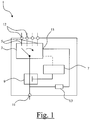
- the multiplexing device 1 comprises a multiplexer 3 provided with a plurality of multiplexing outputs 5, a control unit 7 and coupling means 9 between the control unit and an input 11 of the radio frequency signals.
- the multiplexing outputs 5 are connected to their respective outputs 12 of the radio frequency signals.
- the multiplexing device 1 further comprises means 13 for recovering a DC component of the radio frequency signals connected between the input 11 of said radio frequency signals and a supply input 15 of the multiplexer 3, for supplying power to said multiplexer.
- the multiplexing device 1 is intended to receive at its input 11 radio frequency signals comprising a DC component and a non-DC component, the latter comprising in particular the information to be transmitted between the input 11 and one of the outputs 12. continue also includes information representative of a control of the multiplexing device.
- This part of the non-continuous component is called, in what follows, the control component of the radio frequency signals.
- This control component may be representative of the address of the multiplexing device to be controlled and of the multiplexing output to be activated.
- the control component is extracted from the radiofrequency signals by means of coupling means 9.
- This control component is then sent to the control unit 7 of the multiplexer 3, to activate one of the multiplexing outputs 5 and to transmit the signals. radiofrequency through this output.
- the DC component of the radio frequency signals is, for its part, used to feed the multiplexer 3 by means of recovery means 13 of said component connected to the supply input 15 of the multiplexer 3.
- the coupling means 9 also enable to separate the control component from the DC component.
- the coupling means are generally of electromagnetic type, magnetic field and / or electric field.
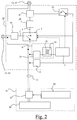
- the multiplexer device 20 is connected through the input 11 and the outputs 12 by means of conductors of two-wire radio frequency signals.
- the conductors of the radio frequency signals could be any other means available to those skilled in the art, for example cables consisting of shielded twisted pairs, coaxial cables, or any other signal conductor radio frequencies with controlled impedance.
- the coupling means 9 comprise a first coil 21 connected to the input 11 of the radio frequency signals and a second coil 23 connected to the control unit 7, magnetically coupled to the first coil and thus producing an AC coupling transformer.
- the first coil has also means 25 for removing the DC component of the radio frequency signals.
- This control component is processed in the control unit 7 to activate one of the multiplexing outputs. 5 of the multiplexer 3 to transmit the radio frequency signals through this multiplexing output
- the multiplexing device 20 comprises two outputs 12 of the radio frequency signals.
- an output 27 of a first type is intended to transmit radio frequency signals comprising a DC component.
- the output of the first type is intended to be connected to an antenna, to the input of another multiplexing device of the same type or to any impedance matching means.
- the DC component transmitted by this output 27 of the first type is used to power this other multiplexing device.
- the multiplexing device 20 comprises means for suppressing the DC component connected between the multiplexer 3 and the output 27 of the first type. These means of suppression 29 of the DC component thus make it possible to transmit, via this output 27 of the first type, only the non-continuous component of the radiofrequency signals.
- the multiplexing device 20 also comprises means 31 for adding the DC component disposed between the DC component suppression means 29 and the first type output 27, these DC component adding means 31 being able to be activated when the output 27 of the first type is connected to the input of another multiplexing device.
- the addition means 31 of the DC component therefore comprise an input of said DC component connected to the recovery means 13 of said DC component through a controlled switch 33.
- the control input of this switch 33 is, as for it, connected to the control unit 7.
- the control unit is designed to close the switch 33 in order to add a DC component to the output 27 of the first type when, on the one hand, the output of the first type 27 has been activated and that, on the other hand, said output 27 is connected to a multiplexer device of the same type.
- This last condition can be verified by means of the control component which can also be representative of the nature of the device connected to the output of the first type 27.
- an output 41 of a second type is intended to transmit radio frequency signals comprising essentially a non-continuous component, that is to say intended to be connected to an antenna only or any means impedance matching.
- the multiplexing device 20 comprises means 43 for removing the DC component connected between the multiplexer 3 and the output 41 of the second type. These DC component suppression means 43 allow the transmission of the non-continuous component of the radio frequency signals to an antenna directly connected to this output 41 of the second type.
- the embodiment of the figure 2 is a partial representation of a monitoring installation comprising a plurality of interconnected multiplexing devices, of which only one of them has been represented under the reference 20.
- the monitoring installation shown in FIG. figure 2 further comprises processing means 51 for transmitting radio frequency signals between said processing means and antennas connected to outputs 12, 27, 41 of the multiplexing devices.
- transmitting radio frequency signals it is generally meant to send a radiofrequency signal from the processing means 51 to one of said antennas and to receive a radiofrequency signal for controlling said antenna towards the processing means, this radio frequency control signal being representative of detecting an object provided with a receiver and disposed along said antenna.
- the processing means comprise a base station 53.
- this base station is a radio-identification type reader, or in English "Radio Frequency IDentification” or abbreviated "RFID”.
- the processing means also comprise a source 55 of the DC component of the radio frequency signals which is superimposed on said radio frequency signals by means of adding means 57 of said DC component.
- the means of processing can transmit to one of the antennas connected to an output of a multiplexing device, radiofrequency signals comprising a DC component for supplying all of the multiplexing devices disposed between said processing means and said antenna.
- the non-continuous component of the radio frequency signals is, for its part, representative of the information to be transmitted, through said antennas, to objects provided with receivers arranged along said antennas.
- This non-continuous component of the radio frequency signals also comprises a control component intended to control the multiplexing devices between the processing means 51 and the antennas.
- this control component of the radio frequency signals can be representative, not only of the multiplexing output to be activated, but also of the nature of the device connected to said output.
- the monitoring system shown comprises processing means 71 for transmitting radio frequency signals to antennas 73 via multiplexing devices 75 having three outputs.
- the multiplexing devices 75 are interconnected by radio frequency signal conductors having a suitable impedance.
- each multiplexing device 75 is associated with a rank J corresponding to the position of said device in said installation relative to the processing means.
- each multiplexing device is associated with a rank J that can range from 1 to 4.
- the input of a multiplexing device associated with a rank J greater than or equal to 2 is connected to an output of a multiplexing device of the directly lower rank J-1.
- This output is often an output of the first type, that is to say intended to transmit radiofrequency signals comprising a DC component.
- Antennas 73 and plugs 77 having a suitable impedance are connected to the remaining outputs. These plugs can also be called termination impedance.
- These remaining outputs are often outputs of the second type, i.e., outputs for transmitting radio frequency signals devoid of DC component.
- an output of the second type can obviously be connected to a plug 77 of suitable impedance.
- each multiplexing device may be outputs of the first type or an association of at least one output of the first type and output of the second type.
- the monitoring installation is implemented in an electrical panel comprising three rows of modular electrical devices 80 such as, for example, switches, switches or circuit breakers.
- the monitoring installation includes processing means 81 for transmitting radio frequency signals to antennas 83 via multiplexing devices 85, 86, 87.
- the antennas 83 are arranged in such a way that the different electrical devices are distributed along said antennas.
- the inputs of the multiplexing devices 86, 87 are connected to an output of the first type 95 of the lower rank multiplexing devices, except for the input of the J-row multiplexing input device 85 which is connected. directly to the processing means 81.
- the output of the first type 95 of the last row multiplexing device is, in turn, connected to a plug 77 of suitable impedance.
- the antennas are connected to the outputs of the second type 97.
- the radio frequency signals are transmitted to said electrical devices by the activation of one of these antennas at a time.
- This transmission generally comprises sending a radiofrequency signal from the processing means 81 to one of said antennas and receiving a radiofrequency signal for controlling said antenna towards the processing means, this radio frequency control signal being representative of detecting electrical devices arranged along said antenna.
- all the multiplexing outputs of the multiplexer device will be connected to suitable impedance loads, such as antennas or plugs, before powering up.
- the output of the first type 95 of the last rank multiplexing device could be connected directly to an antenna which would constitute a load adapted to the output 12.
- the plug 77 it would be possible to replace the plug 77 with a antenna 83 for covering a fourth row without adding a multiplexing device 20.
- N multiplexing device of the type shown in FIG. figure 2 it is possible to cover a number N + 1 of rows of electrical appliances.
- each multiplexing device 85, 86, 87 of the monitoring installation shown in FIG. figure 4 the coupling means 91 between the control unit 93 and the input of the radiofrequency signal use a communication medium of the same type as the antennas 83 and the unrepresented receivers of the electrical devices 80.
- these coupling means 91 of FIG. each multiplexing device uses a communication protocol identical to that used by the antennas 83 and the receivers of the electrical apparatus 80. This makes it possible to simplify the installation by treating the control of the multiplexing devices in the same way as the transmission of information. between the processing means 81 and the various electrical devices 80.
- the two outputs of the radio frequency signals comprise an output 95 of the first type intended to transmit radio frequency signals comprising a DC component and an output 97 of the second type intended to transmit radio frequency signals essentially comprising a non-continuous component.
- the output 95 of each multiplexer device is connected to the input of a higher order multiplexing device.
- the continuous component of the radio frequency signals is transmitted to the multiplexing device of higher order rank to feed the latter.
- each multiplexing device and each antenna connected to the output 97 of the second type of said multiplexing device are supported by the same antenna support 107.
- the antenna supports 107 of the multiplexing devices can be arranged on each row of apparatuses. electric and connected to each other by appropriate impedance radio frequency signal conductors. These antenna supports are thus in the form of modules of a modular set of monitoring.
- control of multiplexing means comprises the activation of an output connected to an antenna of at least one multiplexing device of said multiplexing means by means of a control component of said radio frequency signals.
- the activation of an output of a multiplexing device is performed iteratively so that the activation of an output of a given multiplexing device associated with a rank J greater than or equal to 2 comprises the activation prior to an output of the first type of a lower rank multiplexing device J-1 to which is connected an input of said given multiplexing device.
- the monitoring methods represented on the Figures 5A and 5B are intended for the implementation of an installation of the type of that represented in figure 4 , that is to say having multiplexing devices provided with an output of the first type and an output of the second type.
- the monitoring restarts on the antenna arranged on the output of the second type S2 (1) of the multiplexing device of rank 1.
- the monitoring restarts on the antenna arranged on the output of the second type S2 (1) of the multiplexing device of rank 1.
Claims (13)
- Multiplexierungsvorrichtung (1; 20; 75; 85; 86; 87), die dazu bestimmt ist, mit mindestens einer Vorrichtung des gleichen Typs verbunden zu werden, um Radiofrequenzsignale zwischen Verarbeitungsmitteln (51; 71; 81) und mehreren Antennen (73; 83) zu übertragen, wobei die Multiplexierungsvorrichtung aufweist:- einen Multiplexer (3), der mit mehreren Multiplexausgängen (5) versehen ist,- eine Steuereinheit (7), die ermöglicht, einen der Ausgänge dank einer Steuerkomponente der Radiofrequenzsignale zu aktivieren, und- und Kopplungsmittel (9) zwischen der Steuereinheit und einem Eingang (11) der Radiofrequenzsignale, um die Steuerkomponente an die Steuereinheit zu übertragen,dadurch gekennzeichnet, dass die Vorrichtung mehrere Ausgänge (12) der Radiofrequenzsignale aufweist, umfassend:- mindestens einen Ausgang eines ersten Typs (27; 95), um Radiofrequenzsignale zu übertragen, die eine Gleichkomponente aufweisen, die dazu bestimmt ist, eine andere Multiplexierungsvorrichtung des gleichen Typs zu speisen, die an dem Ausgang des ersten Typs angeschlossen ist, und- mindestens einen Ausgang eines zweiten Typs (41; 97), der dazu bestimmt ist, Radiofrequenzsignale zu übertragen, die im Wesentlichen eine Wechselkomponente aufweisen.
- Vorrichtung nach Anspruch 1, dadurch gekennzeichnet, dass sie Mittel zur Wiederherstellung (13) einer Gleichkomponente der Radiofrequenzsignale aufweist, die an dem Eingang (11) der Signale angeschlossen sind, um die Komponente wiederherzustellen, wobei die Mittel zur Wiederherstellung an einem Stromversorgungseingang (15) des Multiplexers (3) angeschlossen sind, um den Multiplexer mit Strom zu versorgen.
- Vorrichtung nach Anspruch 2, dadurch gekennzeichnet, dass sie Mittel zur Unterdrückung (29, 43) der Gleichkomponente aufweist, die zwischen dem Multiplexer (3) und jedem Ausgang (12, 27, 41) der Vorrichtung angeschlossen sind.
- Vorrichtung nach Anspruch 3, dadurch gekennzeichnet, dass sie Mittel zum Hinzufügen (31) der Gleichkomponente aufweisen, die zwischen den Mitteln zur Unterdrückung (29) der Gleichkomponente und dem mindestens einen Ausgang des ersten Typs (27) angeschlossen sind, wobei die Mittel zum Hinzuzufügen ausgebildet sind, um die Gleichkomponente hinzuzufügen, wenn der Ausgang aktiviert ist und wenn der Ausgang an eine Multiplexierungsvorrichtung des gleichen Typs angeschlossen ist.
- Vorrichtung nach Anspruch 4, dadurch gekennzeichnet, dass sie einen gesteuerten Schalter (33) aufweist, der zwischen dem Eingang der Gleichkomponente der Mittel zum Hinzufügen (31) der Gleichkomponente und den Mitteln zur Wiederherstellung (13) der Gleichkomponente angeschlossen ist, wobei der Schalter einen Steuereingang aufweist, der an der Steuereinheit (7) angeschlossen ist.
- Überwachungsanlage, um Gegenstände (80) zu überwachen, die mit Empfängern ausgestattet sind, wobei die Anlage aufweist:- mehrere Antennen (73; 83), entlang derer die Gegenstände angeordnet sind, um eine elektromagnetische Strahlung zwischen den Antennen und den Empfängern zu übertragen,- Verarbeitungsmittel (51; 71; 81), um Radiofrequenzsignale zwischen den Verarbeitungsmitteln und den Antennen zu übertragen, und- Multiplexierungsmittel, die zwischen den Verarbeitungsmitteln und den Antennen angeschlossen sind, um eine Antenne auszuwählen, an die die Radiofrequenzsignale übertragen werden,dadurch gekennzeichnet, dass die Multiplexierungsmittel mehrere Multiplexierungsvorrichtungen (1, 20; 75; 87) aufweisen, die durch Leiter von Radiofrequenzsignalen miteinander verbunden sind, die eine geeignete Impedanz aufweisen, wobei jede Multiplexierungsvorrichtung eine Vorrichtung nach einem der vorhergehenden Ansprüche ist, wobei die Vorrichtungen dank einer Steuerkomponente der Radiofrequenzsignale gesteuert sind.
- Anlage nach Anspruch 6, dadurch gekennzeichnet, dass jede Multiplexierungsvorrichtung (75; 87) einer Reihe (J) zugeordnet ist, die der Position der Vorrichtung in der Anlage in Bezug auf die Verarbeitungsmittel entspricht, wobei jede Multiplexierungsvorrichtung einen Eingang des Radiofrequenzsignals und mehrere Ausgänge des Radiofrequenzsignals aufweist, wobei der Eingang einer Multiplexierungsvorrichtung, die einer Reihe (J) zugeordnet ist, die höher als oder gleich 2 ist, an einen Ausgang eines ersten Typs angeschlossen ist, der dazu bestimmt ist, Radiofrequenzsignale, die eine Gleichkomponente aufweisen, von einer Multiplexierungsvorrichtung der direkt darunter liegenden Reihe (J-1) zu übertragen, wobei die Antennen an mindestens einen Teil der restlichen Ausgänge angeschlossen sind.
- Anlage nach Anspruch 7, dadurch gekennzeichnet, dass die Kopplungsmittel (9; 91) zwischen der Steuereinheit und dem Eingang des Radiofrequenzsignals ein Kommunikationsmedium des gleichen Typs wie die Antennen (83) und die Empfänger der Gegenstände (80) verwenden.
- Anlage nach Anspruch 8, dadurch gekennzeichnet, dass die Kopplungsmittel (9; 91) von jeder Multiplexierungsvorrichtung ein Kommunikationsprotokoll verwenden, das mit jenem identisch ist, das von den Antennen (83) und den Empfängern der Gegenstände (80) verwendet wird.
- Anlage nach einem der Ansprüche 6 bis 9, dadurch gekennzeichnet, dass die Ausgänge der Radiofrequenzsignale von jeder Multiplexierungsvorrichtung im Wesentlichen aus einem Ausgang eines ersten Typs (27; 95), der dazu bestimmt ist, Radiofrequenzsignale zu übertragen, die eine Gleichkomponente aufweisen, und aus einem Ausgang eines zweiten Typs (41; 97) gebildet sind, der dazu bestimmt ist, Radiofrequenzsignale zu übertragen, die im Wesentlichen eine Wechselkomponente aufweisen.
- Anlage nach Anspruch 10, dadurch gekennzeichnet, dass jede Antenne (83), die an den Ausgang des zweiten Typs angeschlossen ist, von einer modularen Antennenhalterung (107) getragen ist.
- Überwachungsverfahren, um Gegenstände zu überwachen, die mit Empfängern ausgestattet sind, wobei das Verfahren aufweist:- das Übertragen (111, TR(1), TR(J)) von Radiofrequenzsignalen zwischen Verarbeitungsmitteln und Antennen, entlang derer die Gegenstände angeordnet sind,- das Steuern von Multiplexierungsmitteln, die zwischen den Verarbeitungsmitteln und den Antennen angeschlossen sind, um eine Antenne auszuwählen, an die die Radiofrequenzsignale übertragen werden, und- das Übertragen (115, RY(1); RY(J)) einer elektromagnetischen Strahlung zwischen der ausgewählten Antenne und dem Empfänger von mindestens einem Gegenstand, der entlang der Antenne angeordnet ist,wobei das Steuern von Multiplexierungsmitteln das Aktivieren (ACT S2(1), ACT S2(J)) eines Ausgangs, der an eine Antenne von mindestens einer Multiplexierungsvorrichtung der Multiplexierungsmittel angeschlossen ist, mittels einer Steuerkomponente der Radiofrequenzsignale aufweist,
dadurch gekennzeichnet, dass es aufweist:- das Übertragen von Radiofrequenzsignalen, die eine Gleichkomponente aufweisen, über einen Ausgang eines ersten Typs, wobei die Gleichkomponente dazu bestimmt ist, eine andere Multiplexierungsvorrichtung des gleichen Typs zu speisen, die an dem Ausgang des ersten Typs angeschlossen ist, und- das Übertragen von Radiofrequenzsignalen, die im Wesentlichen eine Wechselkomponente aufweisen, über einen Ausgang eines zweiten Typs. - Verfahren nach Anspruch 12, dadurch gekennzeichnet, dass das Aktivieren (ACT S2(J)) eines Ausgangs (S2) einer bestimmten Multiplexierungsvorrichtung, die einer Reihe (J) zugeordnet wird, die höher als oder gleich 2 ist, die der Position der Vorrichtung in Bezug auf die Verarbeitungsmittel entspricht, das vorhergehende Aktivieren (ACT S1(J-1)) eines Ausgangs eines ersten Typs (S1) aufweist, der dazu bestimmt ist, Radiofrequenzsignale, die eine Gleichkomponente aufweisen, von einer Multiplexierungsvorrichtung der direkt darunter liegenden Reihe (J-1) zu übertragen, an den ein Eingang der bestimmten Multiplexierungsvorrichtung angeschlossen ist.
Applications Claiming Priority (1)
| Application Number | Priority Date | Filing Date | Title |
|---|---|---|---|
| FR0904055A FR2949592B1 (fr) | 2009-08-26 | 2009-08-26 | Dispositif de multiplexage, installation de surveillance comportant un tel dispositif et methode de surveillance |
Publications (3)
| Publication Number | Publication Date |
|---|---|
| EP2290632A2 EP2290632A2 (de) | 2011-03-02 |
| EP2290632A3 EP2290632A3 (de) | 2017-11-15 |
| EP2290632B1 true EP2290632B1 (de) | 2019-05-08 |
Family
ID=41720560
Family Applications (1)
| Application Number | Title | Priority Date | Filing Date |
|---|---|---|---|
| EP10354029.0A Active EP2290632B1 (de) | 2009-08-26 | 2010-06-11 | Vorrichtung zum multiplexen, überwachungsanlage mit einer solchen vorrichtung und überwachungsverfahren |
Country Status (4)
| Country | Link |
|---|---|
| EP (1) | EP2290632B1 (de) |
| CN (1) | CN102005315B (de) |
| ES (1) | ES2735219T3 (de) |
| FR (1) | FR2949592B1 (de) |
Families Citing this family (3)
| Publication number | Priority date | Publication date | Assignee | Title |
|---|---|---|---|---|
| CN102332886B (zh) * | 2011-08-16 | 2014-05-21 | 无锡中普微电子有限公司 | 多频带功率放大器 |
| EP2859417B1 (de) * | 2012-06-07 | 2018-01-10 | Schneider Electric Industries SAS | Optimierte kommunikation mit hart-geräte |
| FR3077687B1 (fr) * | 2018-02-05 | 2020-10-16 | Hager Electro Sas | Dispositif pour la surveillance d'au moins une fonction et/ou un etat et/ou de parametres d'un appareil electrique ou d'un tableau electrique, et tableau electrique comprenant ledit dispositif |
Family Cites Families (8)
| Publication number | Priority date | Publication date | Assignee | Title |
|---|---|---|---|---|
| US4890112A (en) * | 1987-06-29 | 1989-12-26 | Raytheon Company | Time multiplexed radar link |
| CH682352A5 (en) * | 1991-02-18 | 1993-08-31 | Sc Techn Dipl Ing Peter A Neuk | Transponder interrogation equipment for remote monitoring system - uses successively switched antenna elements spaced along coaxial cable coupled to base station providing HF interrogation signal |
| JP2001285234A (ja) * | 2000-04-04 | 2001-10-12 | Sony Corp | データ多重化装置およびデータ多重化方法、並びに記録媒体 |
| US7209868B2 (en) * | 2004-02-19 | 2007-04-24 | Hon Hai Precision Industry Co., Ltd. | Signal monitoring system and method |
| GB2432063B (en) * | 2005-11-01 | 2009-09-09 | Zetex Semiconductors Plc | A multiplexer |
| FR2893742B1 (fr) * | 2005-11-22 | 2007-12-21 | Schneider Electric Ind Sas | Dispositif et procede de surveillance pour appareillage c electrique |
| CN101188047A (zh) * | 2006-11-17 | 2008-05-28 | 鸿富锦精密工业(深圳)有限公司 | 多通道差动信号监测电路 |
| US7808274B2 (en) * | 2007-12-28 | 2010-10-05 | Semiconductor Components Industries, Llc | Monolithically integrated multiplexer-translator-demultiplexer circuit and method |
-
2009
- 2009-08-26 FR FR0904055A patent/FR2949592B1/fr active Active
-
2010
- 2010-06-11 ES ES10354029T patent/ES2735219T3/es active Active
- 2010-06-11 EP EP10354029.0A patent/EP2290632B1/de active Active
- 2010-08-26 CN CN201010266036.6A patent/CN102005315B/zh active Active
Non-Patent Citations (1)
| Title |
|---|
| None * |
Also Published As
| Publication number | Publication date |
|---|---|
| ES2735219T3 (es) | 2019-12-17 |
| EP2290632A3 (de) | 2017-11-15 |
| FR2949592A1 (fr) | 2011-03-04 |
| CN102005315B (zh) | 2015-03-04 |
| CN102005315A (zh) | 2011-04-06 |
| EP2290632A2 (de) | 2011-03-02 |
| FR2949592B1 (fr) | 2017-07-21 |
Similar Documents
| Publication | Publication Date | Title |
|---|---|---|
| EP0838909B1 (de) | Vorrichtung zum Erlauben das Gebrauch eines Funkgerätes in einem Flugzeug | |
| EP2290632B1 (de) | Vorrichtung zum multiplexen, überwachungsanlage mit einer solchen vorrichtung und überwachungsverfahren | |
| FR2818454A1 (fr) | Protection pour reseau electrique ayant une liaison radio courte distance dite "bluetooth" | |
| EP3559924B1 (de) | Multifrequenzvorrichtung, steuerungs- und/oder überwachungsvorrichtung, zugehöriges multifrequenzsystem und teil einer heimautomatisierungsanlage | |
| US8337220B2 (en) | Interior network ground | |
| EP3275083B1 (de) | Strom-/daten-elektroverbinder | |
| WO2010072909A1 (fr) | Dispositif electronique a courant porteur | |
| EP1788599B1 (de) | Vorrichtung und Überwachungsverfahren für elektrische Einrichtungen | |
| CA2404504A1 (fr) | Systeme antennaire a rendement eleve et a forte puissance | |
| EP0494030A1 (de) | Funkfernsteuerungsvorrichtung | |
| FR2461420A1 (fr) | Dispositif de transmission ou de transfert pour la commande numerique d'appareils | |
| FR2969428A1 (fr) | Commutateur electronique et appareil de communication incluant un tel commutateur | |
| FR2696890A1 (fr) | Système de transmission de données dans un satellite. | |
| US6603439B2 (en) | Radiating antenna with galvanic insulation | |
| FR2943468A1 (fr) | Prise electrique et alimentation sans interruption equipee d'une telle prise | |
| EP1471749B1 (de) | Signalverteilungseinheit mit einem Verkabelungskonzentrator und Gehäuse mit dieser Einheit | |
| EP2246932B1 (de) | RF-Empfänger/Sender-Vorrichtung für ein durch ein Stromnetz gespeistes Haushaltsgerät | |
| FR2580124A1 (de) | ||
| EP1480434B1 (de) | Verfahren und Vorrichtung zur Energieübertragung in einem drahtgebundenen Telekommunikationssystem | |
| EP2190128A2 (de) | Einrichtung für eine Drahtverbindung zu einer fernen elektrischen Platine. | |
| EP3776882B1 (de) | Datenüvbertragungssystem | |
| FR2992505A1 (fr) | Dispositif de communication par voie d'ondes a emission et/ou reception renforcee(s) au voisinage de cable(s) electrique(s) d'un systeme | |
| FR2794904A1 (fr) | Dispositif de raccordement d'appareils ou de modules electroniques | |
| EP3158656B1 (de) | System zur steuerung von mindestens einem servomotor aus einer befehls-/steuerzentrale | |
| EP1404550B1 (de) | Identifikationsvorrichtung für ein kraftfahrzeug |
Legal Events
| Date | Code | Title | Description |
|---|---|---|---|
| PUAI | Public reference made under article 153(3) epc to a published international application that has entered the european phase |
Free format text: ORIGINAL CODE: 0009012 |
|
| AK | Designated contracting states |
Kind code of ref document: A2 Designated state(s): AL AT BE BG CH CY CZ DE DK EE ES FI FR GB GR HR HU IE IS IT LI LT LU LV MC MK MT NL NO PL PT RO SE SI SK SM TR |
|
| AX | Request for extension of the european patent |
Extension state: BA ME RS |
|
| PUAL | Search report despatched |
Free format text: ORIGINAL CODE: 0009013 |
|
| AK | Designated contracting states |
Kind code of ref document: A3 Designated state(s): AL AT BE BG CH CY CZ DE DK EE ES FI FR GB GR HR HU IE IS IT LI LT LU LV MC MK MT NL NO PL PT RO SE SI SK SM TR |
|
| AX | Request for extension of the european patent |
Extension state: BA ME RS |
|
| RIC1 | Information provided on ipc code assigned before grant |
Ipc: G08C 15/06 20060101AFI20171006BHEP |
|
| STAA | Information on the status of an ep patent application or granted ep patent |
Free format text: STATUS: REQUEST FOR EXAMINATION WAS MADE |
|
| 17P | Request for examination filed |
Effective date: 20171123 |
|
| RBV | Designated contracting states (corrected) |
Designated state(s): AL AT BE BG CH CY CZ DE DK EE ES FI FR GB GR HR HU IE IS IT LI LT LU LV MC MK MT NL NO PL PT RO SE SI SK SM TR |
|
| GRAP | Despatch of communication of intention to grant a patent |
Free format text: ORIGINAL CODE: EPIDOSNIGR1 |
|
| STAA | Information on the status of an ep patent application or granted ep patent |
Free format text: STATUS: GRANT OF PATENT IS INTENDED |
|
| RIC1 | Information provided on ipc code assigned before grant |
Ipc: G08C 15/06 20060101AFI20190123BHEP Ipc: H01H 9/16 20060101ALI20190123BHEP |
|
| INTG | Intention to grant announced |
Effective date: 20190212 |
|
| GRAS | Grant fee paid |
Free format text: ORIGINAL CODE: EPIDOSNIGR3 |
|
| GRAA | (expected) grant |
Free format text: ORIGINAL CODE: 0009210 |
|
| STAA | Information on the status of an ep patent application or granted ep patent |
Free format text: STATUS: THE PATENT HAS BEEN GRANTED |
|
| AK | Designated contracting states |
Kind code of ref document: B1 Designated state(s): AL AT BE BG CH CY CZ DE DK EE ES FI FR GB GR HR HU IE IS IT LI LT LU LV MC MK MT NL NO PL PT RO SE SI SK SM TR |
|
| REG | Reference to a national code |
Ref country code: GB Ref legal event code: FG4D Free format text: NOT ENGLISH |
|
| REG | Reference to a national code |
Ref country code: CH Ref legal event code: EP Ref country code: AT Ref legal event code: REF Ref document number: 1131422 Country of ref document: AT Kind code of ref document: T Effective date: 20190515 |
|
| REG | Reference to a national code |
Ref country code: DE Ref legal event code: R096 Ref document number: 602010058709 Country of ref document: DE Ref country code: IE Ref legal event code: FG4D Free format text: LANGUAGE OF EP DOCUMENT: FRENCH |
|
| REG | Reference to a national code |
Ref country code: NL Ref legal event code: MP Effective date: 20190508 |
|
| REG | Reference to a national code |
Ref country code: LT Ref legal event code: MG4D |
|
| PG25 | Lapsed in a contracting state [announced via postgrant information from national office to epo] |
Ref country code: LT Free format text: LAPSE BECAUSE OF FAILURE TO SUBMIT A TRANSLATION OF THE DESCRIPTION OR TO PAY THE FEE WITHIN THE PRESCRIBED TIME-LIMIT Effective date: 20190508 Ref country code: HR Free format text: LAPSE BECAUSE OF FAILURE TO SUBMIT A TRANSLATION OF THE DESCRIPTION OR TO PAY THE FEE WITHIN THE PRESCRIBED TIME-LIMIT Effective date: 20190508 Ref country code: NL Free format text: LAPSE BECAUSE OF FAILURE TO SUBMIT A TRANSLATION OF THE DESCRIPTION OR TO PAY THE FEE WITHIN THE PRESCRIBED TIME-LIMIT Effective date: 20190508 Ref country code: SE Free format text: LAPSE BECAUSE OF FAILURE TO SUBMIT A TRANSLATION OF THE DESCRIPTION OR TO PAY THE FEE WITHIN THE PRESCRIBED TIME-LIMIT Effective date: 20190508 Ref country code: FI Free format text: LAPSE BECAUSE OF FAILURE TO SUBMIT A TRANSLATION OF THE DESCRIPTION OR TO PAY THE FEE WITHIN THE PRESCRIBED TIME-LIMIT Effective date: 20190508 Ref country code: PT Free format text: LAPSE BECAUSE OF FAILURE TO SUBMIT A TRANSLATION OF THE DESCRIPTION OR TO PAY THE FEE WITHIN THE PRESCRIBED TIME-LIMIT Effective date: 20190908 Ref country code: NO Free format text: LAPSE BECAUSE OF FAILURE TO SUBMIT A TRANSLATION OF THE DESCRIPTION OR TO PAY THE FEE WITHIN THE PRESCRIBED TIME-LIMIT Effective date: 20190808 Ref country code: AL Free format text: LAPSE BECAUSE OF FAILURE TO SUBMIT A TRANSLATION OF THE DESCRIPTION OR TO PAY THE FEE WITHIN THE PRESCRIBED TIME-LIMIT Effective date: 20190508 |
|
| PG25 | Lapsed in a contracting state [announced via postgrant information from national office to epo] |
Ref country code: GR Free format text: LAPSE BECAUSE OF FAILURE TO SUBMIT A TRANSLATION OF THE DESCRIPTION OR TO PAY THE FEE WITHIN THE PRESCRIBED TIME-LIMIT Effective date: 20190809 Ref country code: LV Free format text: LAPSE BECAUSE OF FAILURE TO SUBMIT A TRANSLATION OF THE DESCRIPTION OR TO PAY THE FEE WITHIN THE PRESCRIBED TIME-LIMIT Effective date: 20190508 Ref country code: BG Free format text: LAPSE BECAUSE OF FAILURE TO SUBMIT A TRANSLATION OF THE DESCRIPTION OR TO PAY THE FEE WITHIN THE PRESCRIBED TIME-LIMIT Effective date: 20190808 |
|
| REG | Reference to a national code |
Ref country code: AT Ref legal event code: MK05 Ref document number: 1131422 Country of ref document: AT Kind code of ref document: T Effective date: 20190508 |
|
| REG | Reference to a national code |
Ref country code: ES Ref legal event code: FG2A Ref document number: 2735219 Country of ref document: ES Kind code of ref document: T3 Effective date: 20191217 |
|
| PG25 | Lapsed in a contracting state [announced via postgrant information from national office to epo] |
Ref country code: RO Free format text: LAPSE BECAUSE OF FAILURE TO SUBMIT A TRANSLATION OF THE DESCRIPTION OR TO PAY THE FEE WITHIN THE PRESCRIBED TIME-LIMIT Effective date: 20190508 Ref country code: SK Free format text: LAPSE BECAUSE OF FAILURE TO SUBMIT A TRANSLATION OF THE DESCRIPTION OR TO PAY THE FEE WITHIN THE PRESCRIBED TIME-LIMIT Effective date: 20190508 Ref country code: CZ Free format text: LAPSE BECAUSE OF FAILURE TO SUBMIT A TRANSLATION OF THE DESCRIPTION OR TO PAY THE FEE WITHIN THE PRESCRIBED TIME-LIMIT Effective date: 20190508 Ref country code: AT Free format text: LAPSE BECAUSE OF FAILURE TO SUBMIT A TRANSLATION OF THE DESCRIPTION OR TO PAY THE FEE WITHIN THE PRESCRIBED TIME-LIMIT Effective date: 20190508 Ref country code: EE Free format text: LAPSE BECAUSE OF FAILURE TO SUBMIT A TRANSLATION OF THE DESCRIPTION OR TO PAY THE FEE WITHIN THE PRESCRIBED TIME-LIMIT Effective date: 20190508 Ref country code: DK Free format text: LAPSE BECAUSE OF FAILURE TO SUBMIT A TRANSLATION OF THE DESCRIPTION OR TO PAY THE FEE WITHIN THE PRESCRIBED TIME-LIMIT Effective date: 20190508 |
|
| REG | Reference to a national code |
Ref country code: CH Ref legal event code: PL |
|
| REG | Reference to a national code |
Ref country code: DE Ref legal event code: R097 Ref document number: 602010058709 Country of ref document: DE |
|
| PG25 | Lapsed in a contracting state [announced via postgrant information from national office to epo] |
Ref country code: SM Free format text: LAPSE BECAUSE OF FAILURE TO SUBMIT A TRANSLATION OF THE DESCRIPTION OR TO PAY THE FEE WITHIN THE PRESCRIBED TIME-LIMIT Effective date: 20190508 Ref country code: MC Free format text: LAPSE BECAUSE OF FAILURE TO SUBMIT A TRANSLATION OF THE DESCRIPTION OR TO PAY THE FEE WITHIN THE PRESCRIBED TIME-LIMIT Effective date: 20190508 |
|
| PLBE | No opposition filed within time limit |
Free format text: ORIGINAL CODE: 0009261 |
|
| STAA | Information on the status of an ep patent application or granted ep patent |
Free format text: STATUS: NO OPPOSITION FILED WITHIN TIME LIMIT |
|
| REG | Reference to a national code |
Ref country code: BE Ref legal event code: MM Effective date: 20190630 |
|
| PG25 | Lapsed in a contracting state [announced via postgrant information from national office to epo] |
Ref country code: TR Free format text: LAPSE BECAUSE OF FAILURE TO SUBMIT A TRANSLATION OF THE DESCRIPTION OR TO PAY THE FEE WITHIN THE PRESCRIBED TIME-LIMIT Effective date: 20190508 |
|
| 26N | No opposition filed |
Effective date: 20200211 |
|
| PG25 | Lapsed in a contracting state [announced via postgrant information from national office to epo] |
Ref country code: PL Free format text: LAPSE BECAUSE OF FAILURE TO SUBMIT A TRANSLATION OF THE DESCRIPTION OR TO PAY THE FEE WITHIN THE PRESCRIBED TIME-LIMIT Effective date: 20190508 Ref country code: IE Free format text: LAPSE BECAUSE OF NON-PAYMENT OF DUE FEES Effective date: 20190611 |
|
| PG25 | Lapsed in a contracting state [announced via postgrant information from national office to epo] |
Ref country code: BE Free format text: LAPSE BECAUSE OF NON-PAYMENT OF DUE FEES Effective date: 20190630 Ref country code: LU Free format text: LAPSE BECAUSE OF NON-PAYMENT OF DUE FEES Effective date: 20190611 Ref country code: SI Free format text: LAPSE BECAUSE OF FAILURE TO SUBMIT A TRANSLATION OF THE DESCRIPTION OR TO PAY THE FEE WITHIN THE PRESCRIBED TIME-LIMIT Effective date: 20190508 Ref country code: CH Free format text: LAPSE BECAUSE OF NON-PAYMENT OF DUE FEES Effective date: 20190630 Ref country code: LI Free format text: LAPSE BECAUSE OF NON-PAYMENT OF DUE FEES Effective date: 20190630 |
|
| PG25 | Lapsed in a contracting state [announced via postgrant information from national office to epo] |
Ref country code: CY Free format text: LAPSE BECAUSE OF FAILURE TO SUBMIT A TRANSLATION OF THE DESCRIPTION OR TO PAY THE FEE WITHIN THE PRESCRIBED TIME-LIMIT Effective date: 20190508 |
|
| PG25 | Lapsed in a contracting state [announced via postgrant information from national office to epo] |
Ref country code: IS Free format text: LAPSE BECAUSE OF FAILURE TO SUBMIT A TRANSLATION OF THE DESCRIPTION OR TO PAY THE FEE WITHIN THE PRESCRIBED TIME-LIMIT Effective date: 20190908 |
|
| PG25 | Lapsed in a contracting state [announced via postgrant information from national office to epo] |
Ref country code: MT Free format text: LAPSE BECAUSE OF FAILURE TO SUBMIT A TRANSLATION OF THE DESCRIPTION OR TO PAY THE FEE WITHIN THE PRESCRIBED TIME-LIMIT Effective date: 20190508 Ref country code: HU Free format text: LAPSE BECAUSE OF FAILURE TO SUBMIT A TRANSLATION OF THE DESCRIPTION OR TO PAY THE FEE WITHIN THE PRESCRIBED TIME-LIMIT; INVALID AB INITIO Effective date: 20100611 |
|
| PG25 | Lapsed in a contracting state [announced via postgrant information from national office to epo] |
Ref country code: MK Free format text: LAPSE BECAUSE OF FAILURE TO SUBMIT A TRANSLATION OF THE DESCRIPTION OR TO PAY THE FEE WITHIN THE PRESCRIBED TIME-LIMIT Effective date: 20190508 |
|
| PGFP | Annual fee paid to national office [announced via postgrant information from national office to epo] |
Ref country code: FR Payment date: 20230622 Year of fee payment: 14 Ref country code: DE Payment date: 20230627 Year of fee payment: 14 |
|
| PGFP | Annual fee paid to national office [announced via postgrant information from national office to epo] |
Ref country code: IT Payment date: 20230620 Year of fee payment: 14 Ref country code: GB Payment date: 20230620 Year of fee payment: 14 Ref country code: ES Payment date: 20230721 Year of fee payment: 14 |