EP2290539A1 - Découverte de topologie virtuelle de configuration d'ordinateur - Google Patents
Découverte de topologie virtuelle de configuration d'ordinateur Download PDFInfo
- Publication number
- EP2290539A1 EP2290539A1 EP20100184363 EP10184363A EP2290539A1 EP 2290539 A1 EP2290539 A1 EP 2290539A1 EP 20100184363 EP20100184363 EP 20100184363 EP 10184363 A EP10184363 A EP 10184363A EP 2290539 A1 EP2290539 A1 EP 2290539A1
- Authority
- EP
- European Patent Office
- Prior art keywords
- cpu
- cpus
- tle
- tles
- topology
- Prior art date
- Legal status (The legal status is an assumption and is not a legal conclusion. Google has not performed a legal analysis and makes no representation as to the accuracy of the status listed.)
- Granted
Links
- 230000015654 memory Effects 0.000 claims abstract description 34
- 230000010287 polarization Effects 0.000 claims description 49
- 238000000034 method Methods 0.000 claims description 39
- 238000012545 processing Methods 0.000 claims description 22
- 101100457021 Caenorhabditis elegans mag-1 gene Proteins 0.000 claims description 14
- 101100067996 Mus musculus Gbp1 gene Proteins 0.000 claims description 14
- 238000004590 computer program Methods 0.000 claims description 6
- MGIUUAHJVPPFEV-ABXDCCGRSA-N magainin ii Chemical compound C([C@H](NC(=O)[C@H](CCCCN)NC(=O)CNC(=O)[C@@H](NC(=O)CN)[C@@H](C)CC)C(=O)N[C@@H](CC(C)C)C(=O)N[C@@H](CC=1NC=NC=1)C(=O)N[C@@H](CO)C(=O)N[C@@H](C)C(=O)N[C@@H](CCCCN)C(=O)N[C@@H](CCCCN)C(=O)N[C@@H](CC=1C=CC=CC=1)C(=O)NCC(=O)N[C@@H](CCCCN)C(=O)N[C@@H](C)C(=O)N[C@@H](CC=1C=CC=CC=1)C(=O)N[C@@H](C(C)C)C(=O)NCC(=O)N[C@@H](CCC(O)=O)C(=O)N[C@@H]([C@@H](C)CC)C(=O)N[C@@H](CCSC)C(=O)N[C@@H](CC(N)=O)C(=O)N[C@@H](CO)C(O)=O)C1=CC=CC=C1 MGIUUAHJVPPFEV-ABXDCCGRSA-N 0.000 claims description 6
- 238000005192 partition Methods 0.000 description 82
- 230000006870 function Effects 0.000 description 52
- 239000013256 coordination polymer Substances 0.000 description 23
- 238000003860 storage Methods 0.000 description 19
- 230000008859 change Effects 0.000 description 14
- 230000008569 process Effects 0.000 description 12
- 238000013519 translation Methods 0.000 description 12
- 230000014616 translation Effects 0.000 description 12
- 230000000694 effects Effects 0.000 description 9
- 238000004519 manufacturing process Methods 0.000 description 8
- 238000000638 solvent extraction Methods 0.000 description 8
- 230000009471 action Effects 0.000 description 7
- 238000013507 mapping Methods 0.000 description 7
- 238000004422 calculation algorithm Methods 0.000 description 6
- 238000005516 engineering process Methods 0.000 description 6
- 238000012360 testing method Methods 0.000 description 6
- 238000006073 displacement reaction Methods 0.000 description 5
- 241000196324 Embryophyta Species 0.000 description 4
- 239000000872 buffer Substances 0.000 description 4
- 238000004891 communication Methods 0.000 description 4
- 230000008878 coupling Effects 0.000 description 4
- 238000010168 coupling process Methods 0.000 description 4
- 238000005859 coupling reaction Methods 0.000 description 4
- 238000007667 floating Methods 0.000 description 4
- 230000004044 response Effects 0.000 description 4
- 101000966782 Homo sapiens Lysophosphatidic acid receptor 1 Proteins 0.000 description 3
- 101001038001 Homo sapiens Lysophosphatidic acid receptor 2 Proteins 0.000 description 3
- 102100040607 Lysophosphatidic acid receptor 1 Human genes 0.000 description 3
- 102100040387 Lysophosphatidic acid receptor 2 Human genes 0.000 description 3
- 101100386699 Neurospora crassa (strain ATCC 24698 / 74-OR23-1A / CBS 708.71 / DSM 1257 / FGSC 987) dcl-1 gene Proteins 0.000 description 3
- 230000001174 ascending effect Effects 0.000 description 3
- 230000008901 benefit Effects 0.000 description 3
- 238000009434 installation Methods 0.000 description 3
- 238000007726 management method Methods 0.000 description 3
- 239000003607 modifier Substances 0.000 description 3
- 230000008520 organization Effects 0.000 description 3
- 101001038006 Homo sapiens Lysophosphatidic acid receptor 3 Proteins 0.000 description 2
- 102100040388 Lysophosphatidic acid receptor 3 Human genes 0.000 description 2
- 238000003491 array Methods 0.000 description 2
- 230000006399 behavior Effects 0.000 description 2
- 238000012512 characterization method Methods 0.000 description 2
- 238000011161 development Methods 0.000 description 2
- 230000007246 mechanism Effects 0.000 description 2
- 230000006855 networking Effects 0.000 description 2
- 238000004806 packaging method and process Methods 0.000 description 2
- 230000009467 reduction Effects 0.000 description 2
- 230000011664 signaling Effects 0.000 description 2
- 238000004088 simulation Methods 0.000 description 2
- 241000208199 Buxus sempervirens Species 0.000 description 1
- 101100457838 Caenorhabditis elegans mod-1 gene Proteins 0.000 description 1
- 101150110972 ME1 gene Proteins 0.000 description 1
- 230000002776 aggregation Effects 0.000 description 1
- 238000004220 aggregation Methods 0.000 description 1
- 230000004075 alteration Effects 0.000 description 1
- 238000004364 calculation method Methods 0.000 description 1
- 238000006243 chemical reaction Methods 0.000 description 1
- 230000001427 coherent effect Effects 0.000 description 1
- 238000001816 cooling Methods 0.000 description 1
- 230000008030 elimination Effects 0.000 description 1
- 238000003379 elimination reaction Methods 0.000 description 1
- 239000004744 fabric Substances 0.000 description 1
- 230000002349 favourable effect Effects 0.000 description 1
- 230000006872 improvement Effects 0.000 description 1
- 230000000977 initiatory effect Effects 0.000 description 1
- 238000009413 insulation Methods 0.000 description 1
- 230000003993 interaction Effects 0.000 description 1
- 230000007774 longterm Effects 0.000 description 1
- 238000005457 optimization Methods 0.000 description 1
- 238000012856 packing Methods 0.000 description 1
- 230000002093 peripheral effect Effects 0.000 description 1
- 238000011176 pooling Methods 0.000 description 1
- 238000007781 pre-processing Methods 0.000 description 1
- 238000011084 recovery Methods 0.000 description 1
- 230000008439 repair process Effects 0.000 description 1
- 238000000926 separation method Methods 0.000 description 1
- 238000004904 shortening Methods 0.000 description 1
- 229920000638 styrene acrylonitrile Polymers 0.000 description 1
- 238000012546 transfer Methods 0.000 description 1
- 230000001131 transforming effect Effects 0.000 description 1
Images


Classifications
-
- H—ELECTRICITY
- H04—ELECTRIC COMMUNICATION TECHNIQUE
- H04L—TRANSMISSION OF DIGITAL INFORMATION, e.g. TELEGRAPHIC COMMUNICATION
- H04L41/00—Arrangements for maintenance, administration or management of data switching networks, e.g. of packet switching networks
- H04L41/12—Discovery or management of network topologies
-
- G—PHYSICS
- G06—COMPUTING; CALCULATING OR COUNTING
- G06F—ELECTRIC DIGITAL DATA PROCESSING
- G06F9/00—Arrangements for program control, e.g. control units
- G06F9/06—Arrangements for program control, e.g. control units using stored programs, i.e. using an internal store of processing equipment to receive or retain programs
- G06F9/30—Arrangements for executing machine instructions, e.g. instruction decode
- G06F9/30003—Arrangements for executing specific machine instructions
-
- G—PHYSICS
- G06—COMPUTING; CALCULATING OR COUNTING
- G06F—ELECTRIC DIGITAL DATA PROCESSING
- G06F9/00—Arrangements for program control, e.g. control units
- G06F9/06—Arrangements for program control, e.g. control units using stored programs, i.e. using an internal store of processing equipment to receive or retain programs
- G06F9/44—Arrangements for executing specific programs
- G06F9/455—Emulation; Interpretation; Software simulation, e.g. virtualisation or emulation of application or operating system execution engines
- G06F9/45533—Hypervisors; Virtual machine monitors
- G06F9/45545—Guest-host, i.e. hypervisor is an application program itself, e.g. VirtualBox
-
- G—PHYSICS
- G06—COMPUTING; CALCULATING OR COUNTING
- G06F—ELECTRIC DIGITAL DATA PROCESSING
- G06F9/00—Arrangements for program control, e.g. control units
- G06F9/06—Arrangements for program control, e.g. control units using stored programs, i.e. using an internal store of processing equipment to receive or retain programs
- G06F9/44—Arrangements for executing specific programs
- G06F9/455—Emulation; Interpretation; Software simulation, e.g. virtualisation or emulation of application or operating system execution engines
- G06F9/45533—Hypervisors; Virtual machine monitors
- G06F9/45558—Hypervisor-specific management and integration aspects
-
- G—PHYSICS
- G06—COMPUTING; CALCULATING OR COUNTING
- G06F—ELECTRIC DIGITAL DATA PROCESSING
- G06F9/00—Arrangements for program control, e.g. control units
- G06F9/06—Arrangements for program control, e.g. control units using stored programs, i.e. using an internal store of processing equipment to receive or retain programs
- G06F9/46—Multiprogramming arrangements
- G06F9/50—Allocation of resources, e.g. of the central processing unit [CPU]
- G06F9/5061—Partitioning or combining of resources
- G06F9/5077—Logical partitioning of resources; Management or configuration of virtualized resources
-
- G—PHYSICS
- G06—COMPUTING; CALCULATING OR COUNTING
- G06F—ELECTRIC DIGITAL DATA PROCESSING
- G06F9/00—Arrangements for program control, e.g. control units
- G06F9/06—Arrangements for program control, e.g. control units using stored programs, i.e. using an internal store of processing equipment to receive or retain programs
- G06F9/44—Arrangements for executing specific programs
- G06F9/455—Emulation; Interpretation; Software simulation, e.g. virtualisation or emulation of application or operating system execution engines
- G06F9/45533—Hypervisors; Virtual machine monitors
- G06F9/45558—Hypervisor-specific management and integration aspects
- G06F2009/45566—Nested virtual machines
Definitions
- the present invention relates in general to virtualization of multi-processor systems.
- the present invention relates to enabling programs to discover the topology of their virtual environment.
- An LPAR is a subset of the processor hardware that is defined to support an operating system.
- An LPAR contains resources (processors, memory, and input/output devices) and operates as an independent system. Multiple logical partitions can exist within a mainframe hardware system.
- PR/SMTM Processor Resource/System Manager
- System administrators assign portions of memory to each LPAR and memory cannot be shared among LPARs.
- the administrators can assign processors (also known as CPs or CPUs) to specific LPARs or they can allow the system controllers to dispatch any or all the processors to all the LPARs using an internal load-balancing algorithm.
- Channels can be assigned to specific LPARs or can be shared by multiple LPARs, depending on the nature of the devices on each channel.
- a system with a single processor can have multiple LPARs.
- PR/SM has an internal dispatcher that can allocate a portion of the processor to each LPAR, much as an operating system dispatcher allocates a portion of its processor time to each process, thread, or task.
- Partitioning control specifications are partly contained in the IOCDS and are partly contained in a system profile.
- the IOCDS and profile both reside in the Support Element (SE) which is simply a notebook computer inside the system.
- SE Support Element
- the SE can be connected to one or more Hardware Management Consoles (HMCs), which are desktop personal computers used to monitor and control hardware such as the mainframe microprocessors
- HMCs Hardware Management Consoles
- An HMC is more convenient to use than an SE and can control several different mainframes.
- an operator prepares a mainframe for use by selecting and loading a profile and an IOCDS. These create LPARs and configure the channels with device numbers, LPAR assignments, multiple path information, and so forth. This is known as a Power-on Reset (POR).
- POR Power-on Reset
- the operator can completely change the number and nature of LPARs and the appearance of the I/O configuration. However, doing this is usually disruptive to any running operating systems and applications and is therefore seldom done without advance planning.
- Logical partitions are, in practice, equivalent to separate mainframes.
- Each LPAR runs its own operating system. This can be any mainframe operating system; there is no need to run z/OS®, for example, in each LPAR.
- the installation planners may elect to share I/O devices across several LPARs, but this is a local decision.
- the system administrator can assign one or more system processors for the exclusive use of an LPAR. Alternately, the administrator can allow all processors to be used on some or all LPARs.
- the system control functions (often known as microcode or firmware) provide a dispatcher to share the processors among the selected LPARs.
- the administrator can specify a maximum number of concurrent processors executing in each LPAR.
- the administrator can also provide weightings for different LPARs; for example, specifying that LPAR1 should receive twice as much processor time as LPAR2.
- each LPAR has its own copy of its operating system, has its own operator console (if needed), and so forth. If the system in one LPAR crashes, there is no effect on the other LPARs.
- a mainframe system with three LPARs for example, you might have a production z/OS in LPAR1, a test version of z/OS in LPAR2, and Linux® for S/390® in LPAR3. If this total system has 8 GB of memory, we might have assigned 4 GB to LPAR1, 1 GB to LPAR2, 1 GB to LPAR3, and have kept 2 GB in reserve.
- the operating system consoles for the two z/OS LPARs might be in completely different locations.
- the minor differences include the ability of z/OS (if permitted when the LPARs were defined) to obtain performance and utilization information across the complete mainframe system and to dynamically shift resources (processors and channels) among LPARs to improve performance.
- CPC central processor complex
- processors in the CPC begin as equivalent processor units (PUs) or engines that have not been characterized for use.
- processors are characterized by IBM during installation or at a later time. The potential characterizations are:
- ICF Integrated Coupling Facility
- processors run only Licensed Internal Code. They are not visible to normal operating systems or applications.
- a coupling facility is, in effect, a large memory scratch pad used by multiple systems to coordinate work. ICFs must be assigned to LPARs that then become coupling facilities.
- An uncharacterized PU functions as a "spare.” If the system controllers detect a failing CP or SAP, it can be replaced with a spare PU. In most cases this can be done without any system interruption, even for the application running on the failing processor.
- mainframes In addition to these characterizations of processors, some mainframes have models or versions that are configured to operate slower than the potential speed of their CPs. This is widely known as "knee-capping", although IBM prefers the term capacity setting, or something similar. It is done by using microcode to insert null cycles into the processor instruction stream. The purpose, again, is to control software costs by having the minimum mainframe model or version that meets the application requirements. IFLs, SAPs, zAAPs, zIIPs, and ICFs always function at the full speed of the processor because these processors "do not count” in software pricing calculations.
- processors can refer to either the complete system box, or to one of the processors (CPUs) within the system box.
- CPU central processor complex
- IBM uses the term central processor complex (CPC) to refer to the physical collection of hardware that includes main storage, one or more central processors, timers, and channels.
- CPC central electronic complex
- CEC central electronic complex
- PUs processing units
- CPs for normal work
- IFL Integrated Facility for Linux
- ICF Integrated Coupling Facility
- Mainframe professionals typically use system to indicate the hardware box, a complete hardware environment (with I/O devices), or an operating environment (with software), depending on the context. They typically use processor to mean a single processor (CP) within the CPC.
- processor typically use processor to mean a single processor (CP) within the CPC.
- the z/VM® HYPERVISORTM is designed to help clients extend the business value of mainframe technology across the enterprise by integrating applications and data while providing exceptional levels of availability, security, and operational ease.
- z/VM virtualization technology is designed to allow the capability for clients to run hundreds to thousands of Linux servers on a single mainframe running with other System z operating systems, such as z/OS®, or as a large-scale Linux-only enterprise server solution.
- z/VM V5.3 can also help to improve productivity by hosting non-Linux workloads such as z/OS, z/VSE, and z/TPF.
- z/VM provides each user with an individual working environment known as a virtual machine.
- the virtual machine simulates the existence of a dedicated real machine, including processor functions, memory, networking, and input/output (I/O) resources.
- Operating systems and application programs can run in virtual machines as guests. For example, you can run multiple Linux and z/OS images on the same z/VM system that is also supporting various applications and end users. As a result, development, testing, and production environments can share a single physical computer.
- partitioning and virtualization involve a shift in thinking from physical to logical by treating IT resources as logical pools rather than as separate physical entities. This involves consolidating and pooling IT resources, and providing a "single system illusion" for both homogeneous and heterogeneous servers, storage, distributed systems, and networks.
- Partitioning of hardware involves separate CPUs for separate operating systems, each of which runs its specific applications.
- Software partitioning employs a software-based "hypervisor" to enable individual operating systems to run on any or all of the CPUs.
- Hypervisors allow multiple operating systems to run on a host computer at the same time.
- Hypervisor technology originated in the IBM VM/370, the predecessor of the z/VM we have today.
- Logical partitioning involves partitioning firmware (a hardware-based hypervisor) to isolate the operating system from the CPUs.
- Virtualization enables or exploits four fundamental capabilities: resource sharing, resource aggregation, emulation of function, and insulation. We explore these topics in more detail in the following sections.
- z/VM is an operating system for the IBM System z platform that provides a highly flexible test and production environment.
- the z/VM implementation of IBM virtualization technology provides the capability to run full-function operating systems such as Linux on System z, z/OS, and others as "guests" of z/VM.
- z/VM supports 64-bit IBM z/Architecture guests and 31-bit IBM Enterprise Systems Architecture/390 guests.
- z/VM provides each user with an individual working environment known as a virtual machine.
- the virtual machine simulates the existence of a dedicated real machine, including processor functions, memory, networking, and input/output (I/O) resources.
- Operating systems and application programs can run in virtual machines as guests. For example, you can run multiple Linux and z/OS® images on the same z/VM system that is also supporting various applications and end users. As a result, development, testing, and production environments can share a single physical computer.
- a virtual machine uses real hardware resources, but even with dedicated devices (like a tape drive), the virtual address of the tape drive may or may not be the same as the real address of the tape drive. Therefore, a virtual machine only knows "virtual hardware" that may or may not exist in the real world.
- a first-level z/VM is the base operating system that is installed on top of the real hardware FIG 16 .
- a second-level operating system is a system that is created upon the base z/VM operating system. Therefore, z/VM as a base operating system runs on the hardware, while a guest operating system runs on the virtualization technology.
- FIG 14 illustrates a second level guest z/VM OS loaded into a first level guest (guest-1) partition.
- FIG. 14 illustrates virtualization by resource emulation.
- Examples include architecture emulation software that implements one processor's architecture using another; iSCSI, which implements a virtual SCSI bus on an IP network; and virtual-tape storage implemented on physical disk storage.
- CPUs central-processing units
- modem technology is often hierarchical. Multiple cores can be placed on a single chip. Multiple chips can be placed in a single module. Multiple modules can be packaged on a board often referred to as a book, and multiple books can be distributed across multiple frames.
- each processor may have a cache (or possibly a split Instruction cache and a data cache) and there may be additional larger caches between each processor and the main memory interface.
- caches are also placed in order to improve overall performance, and at certain levels, a cache may be shared among more than a single CPU.
- the engineering decisions regarding such placement deal with space, power/thermal, cabling distances, CPU frequency, system performance, and other aspects. This placement of elements of the CPU creates an internal structure that can be more or less favorable to a particular logical partition, depending upon where the placement of each CPU of the partition resides.
- a logical partition gives the appearance to an operating system, of ownership of certain resources including processor utilization where in actuality, the operating system is sharing the resources with other operating systems in other partitions.
- software is not aware of the placement and, in a symmetric-multiprocessing (SMP) configuration, observes a set of CPUs where each provides the same level of performance.
- SMP symmetric-multiprocessing
- the mainframe example of virtualization presented is intended to teach various topologies possible in virtualizing a machine.
- the programs running in a partition likely have a view that the resources available to them, including the processors, memory and I/O are dedicated to the partition.
- programs do not have any idea that they are running in a partition.
- Such programs are also not aware of the topology of their partition and therefore can not make choices based on such topology. What is needed is a way for programs to optimize for the configuration topology on which they are running.
- EP-A-1 674,987 discloses a method according to the pre-characterizing portion of claim 1.
- the invention provides a method as claimed in claim 1 and corresponding system and computer program.
- a host computer comprising host CPUs can be partitioned into logical/virtual partitions having guest CPUs.
- the partitioning is preferably accomplished by firmware or by software as might be provided by an operating system such as z/VM from IBM.
- Each guest CPU is a virtual CPU in that the guest programs view the guest CPUs as actual CPU processors, but in fact, the underlying host is mapping each guest CPU to host CPU resources.
- a guest CPU is implemented using a portion of a host CPU by the host designating a portion of CPU time for the guest CPU to utilize the host CPU. It is envisioned that a plurality of guest CPUs might be supported by a single host CPU but the opposite may also apply.
- the guest CPUs are emulated by software whereby, emulation routines convert functions of the guest CPU (including instruction decode and execution) to routines that run on host CPUs.
- the host CPUs are provisioned to support guest CPUs.
- a first guest image may be the host of a second guest image.
- the second guest CPUs are provisioned by first guest CPUs which are themselves provisioned by host CPUs.
- the topology of the configurations is a nesting of levels of guest CPUs and one or more host CPUs.
- a new PERFORM TOPOLOGY FACILITY (PTF) instruction is provided and the prior art STORE SYSTEM INFORMATION (STSI) instruction is enhanced to provide a new SYSIB (SYSIB identifier 15.1.2) which provides component affinity and logical packaging information to software.
- STSI STORE SYSTEM INFORMATION
- OS program
- a new PERFORM TOPOLOGY FUNCTION (PTF) instruction is used by a privileged program such as a supervisor, an OS, a kernel and the like) to request that the CPU configuration topology within which the program is running be changed.
- a privileged program such as a supervisor, an OS, a kernel and the like
- the guest CPU topology is switched between horizontal and vertical polarization.
- the program By having the capability to learn the CPU topology information, the program understands the "distance" between any arbitrary two or more CPUs of a symmetric-multiprocessing configuration.
- the capability provided for minimizing the aggregate distance of all CPUs in a configuration, and how particular application-program tasks are dispatched on the individual CPUs provides supervisory programs with the ability to improve performance.
- the improved performance can result from one or more of the following attributes which are improved by better topology knowledge:
- the number of CPUs actually in the configuration can be fewer in number, while still getting the same job done in the same or less run time.
- Such reduction of CPUs lessens the number of communication paths that each CPU must use to communicate with the other CPUs of the configuration, thereby further contributing to overall performance improvement.
- the inter-cache traffic is substantial whereas if the same program can be executed on one CPU, there is no inter-cache traffic. This indicates that the cache presence of desired storage locations is guaranteed to be in the cache of the single CPU, if that storage is in any cache at all.
- Topology knowledge indicates the relative distance in selecting the appropriate subset of CPUs to assign to an application program such that, even within a larger set of CPUs in an SMP configuration, the subset optimizes the minimized distance among them. This is sometimes called an affinity group
- topology information is discovered of one or more guest processors (guest CPUs) of a guest configuration and stored in a table.
- a guest processor of the guest configuration fetches a STORE SYSTEM INFORMATION instruction for execution.
- the STORE SYSTEM INFORMATION instruction based on a topology information request of the STORE SYSTEM INFORMATION instruction, obtains topology information of the computer configuration the topology information comprising nesting information of processors of the configuration.
- the topology information obtained is stored in a configuration topology table preferably in memory.
- the topology information comprises identification of host processors and nesting levels associated with topology of the host processors. In another embodiment, the topology information comprises information about host processors of guest configuration and nesting levels associated with the topology of the host processors of the guest configuration.
- the STORE SYSTEM INFORMATION instruction comprises an opcode field, a base register field, a signed displacement field
- the topology discovery instruction further comprises a first implied general register containing a function code field and a selector-1 field and a second implied general register containing a selector-2 field, the function code field specifying the topology information request, the base register field and the signed displacement field identifying a location in memory of a system information block (SYSIB) containing the configuration topology table, wherein values of the selector-1 field and the selector-2 field, in combination, determine the topology information request to be performed.
- SYSIB system information block
- the table includes a topology list processor entry for each group of nested processors of the processors.
- the topology list processor entry further comprises an indicator indicting how dedicated the processors of the group of nested processors are to the logical partition guest configuration.
- the table further includes a topology list container entry of each nesting level for a hierarchy of one or more nesting levels having said nested processors.
- the execution of the STORE SYSTEM INFORMATION is performed by emulation on an alien processor.
- architected machine instructions are used by programmers (typically writing applications in "C” but also Java®, COBOL, PL/I, PL/X, Fortran and other high level languages), often by way of a compiler application.
- These instructions stored in the storage medium may be executed natively in a z/Architecture IBM Server, or alternatively in machines executing other architectures. They can be emulated in the existing and in future IBM mainframe servers and on other machines of IBM (e.g. pSeries® Servers and xSeries® Servers). They can be executed in machines running Linux on a wide variety of machines using hardware manufactured by IBM®, Intel®, AMDTM, Sun Microsystems and others.
- Linux can be used as well as machines which use emulation by Hercules, UMX, FSI (Fundamental Software, Inc) or Platform Solutions, Inc. (PSI), where generally execution is in an emulation mode.
- emulation mode emulation software is executed by a native processor to emulate the architecture of an emulated processor.
- the native processor typically executes emulation software comprising either firmware or a native operating system to perform emulation of the emulated processor.
- the emulation software is responsible for fetching and executing instructions of the emulated processor architecture.
- the emulation software maintains an emulated program counter to keep track of instruction boundaries.
- the emulation software may fetch one or more emulated machine instructions at a time and convert the one or more emulated machine instructions to a corresponding group of native machine instructions for execution by the native processor. These converted instructions may be cached such that a faster conversion can be accomplished.
- the emulation software must maintain the architecture rules of the emulated processor architecture so as to assure operating systems and applications written for the emulated processor operate correctly.
- the emulation software must provide resources identified by the emulated processor architecture including, but not limited to control registers, general purpose registers (often including floating point registers), dynamic address translation function including segment tables and page tables for example, interrupt mechanisms, context switch mechanisms, Time of Day (TOD) clocks and architected interfaces to I/O subsystems such that an operating system or an application program designed to run on the emulated processor, can be run on the native processor having the emulation software.
- control registers general purpose registers (often including floating point registers)
- dynamic address translation function including segment tables and page tables for example, interrupt mechanisms, context switch mechanisms, Time of Day (TOD) clocks and architected interfaces to I/O subsystems such that an operating system or an application program designed to run on the emulated processor, can be run on the native processor having the emulation software.
- a specific instruction being emulated is decoded, and a subroutine called to perform the function of the individual instruction.
- An emulation software function emulating a function of an emulated processor is implemented, for example, in a "C" subroutine or driver, or some other method of providing a driver for the specific hardware as will be within the skill of those in the art after understanding the description of the preferred embodiment.
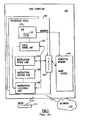
- FIG. 1 representative components of a host computer system 100 are portrayed. Other arrangements of components may also be employed in a computer system which are well known in the art.
- the host computing environment is preferably based on the z/Architecture offered by International Business Machines Corporation (IBM ® ), Armonk, New York.
- IBM ® International Business Machines Corporation
- the z/Architecture is more fully described in: z / Architecture Principles of operation, IBM ® Pub. No. SA22-7832-05, 6 th Edition, (April 2007).
- Computing environments based on the z/Architecture include, for example, eServerTM and zSeries ® , both by IBM ® .
- the representative host computer 100 comprises one or more CPUs 101 in communication with main store (computer memory 102) as well as I/O interfaces to storage devices 111 and networks 101 for communicating with other computers or SANs and the like.
- the CPU may have Dynamic Address Translation (DAT) 103 for transforming program addresses (virtual addresses) into real address of memory.
- a DAT typically includes a Translation Lookaside Buffer (TLB) 107 for caching translations so that later accesses to the block of computer memory 102 do not require the delay of address translation.
- TLB Translation Lookaside Buffer
- a cache 109 is employed between computer memory 102 and the Processor 101.
- the cache 109 may be hierarchical having a large cache available to more than one CPU and smaller, faster (lower level) caches between the large cache and each CPU.
- the lower level caches are split to provide separate low level caches for instruction fetching and data accesses.
- an instruction is fetched from memory 102 by an instruction fetch unit 104 via a cache 109.
- the instruction is decoded in an instruction decode unit (706) and dispatched (with other instructions in some embodiments) to instruction execution units 108.
- instruction execution units 108 typically several execution units 108 are employed, for example an arithmetic execution unit, a floating point execution unit and a branch instruction execution unit.
- the instruction is executed by the execution unit, accessing operands from instruction specified registers or memory as needed. If an operand is to be accessed (loaded or stored) from memory 102, a load store unit 105 typically handles the access under control of the instruction being executed.
- the invention may be practiced by software (sometimes referred to Licensed Internal Code (LIC), firmware, micro-code, milli-code, pico-code and the like, any of which would be consistent with the present invention).
- Software program code which embodies the present invention is typically accessed by the processor also known as a CPU (Central Processing Unit) 101 of computer system 100 from long term storage media 111, such as a CD-ROM drive, tape drive or hard drive.
- the software program code may be embodied on any of a variety of known media for use with a data processing system, such as a diskette, hard drive, or CD-ROM.
- the code may be distributed on such media, or may be distributed to users from the computer memory 102 or storage of one computer system over a network 110 to other computer systems for use by users of such other systems.
- the program code may be embodied in the memory 102, and accessed by the processor 101 using the processor bus.
- Such program code includes an operating system which controls the function and interaction of the various computer components and one or more application programs.
- Program code is normally paged from dense storage media 111 to high speed memory 102 where it is available for processing by the processor 101.
- the techniques and methods for embodying software program code in memory, on physical media, and/or distributing software code via networks are well known and will not be further discussed herein.
- Program code when created and stored on a tangible medium (including but not limited to electronic memory modules (RAM), flash memory, compact discs (CDs), DVDs, magnetic tape and the like is often referred to as a "computer program product".
- the computer program product medium is typically readable by a processing circuit preferably in a computer system for execution by the processing circuit.
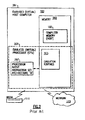
- an example emulated host computer system 201 is provided that emulates a host computer system 100 of a host architecture.
- the host processor (CPUs) 208 is an emulated host processor (or virtual host processor) and comprises an emulation processor 207 having a different native instruction set architecture than that of used by the processor 101 of the host computer 100.
- the emulated host computer system 201 has memory 202 accessible to the emulation processor 207.
- the memory 207 is partitioned into a host computer memory 102 portion and an emulation routines 203 portion.
- the host computer memory 102 is available to programs of the emulated host computer 201 according to host computer architecture.
- the emulation processor 207 executes native instructions of an architected instruction set of an architecture other than that of the emulated processor 208, the native instructions obtained from emulation routines memory 203, and may access a host instruction for execution from a program in host computer memory 102 by employing one or more instruction(s) obtained in a Sequence & Access/Decode routine which may decode the host instruction(s) accessed to determine a native instruction execution routine for emulating the function of the host instruction accessed.
- Architected Facilities Routines including such facilities as General Purpose Registers, Control Registers, Dynamic Address Translation, and I/O Subsystem support and processor cache for example.
- the emulation routines may also take advantage of function available in the emulation processor 207 (such as General Registers and dynamic translation of virtual addresses) to improve performance of the emulation routines.
- Special hardware and Off Load Engines may also be provided to assist the processor 207 in emulating the function of the host computer 100.
- the first is an enhancement to a prior art instruction STSI (STORE SYSTEM INFORMATION) and the second is a new instruction PTF (PERFORM TOPOLOGY FUNCTION).
- the purpose of the new SYSIB 15.1.2 function of the prior art STSI (STORE SYSTEM INFORMATION) instruction and the new PERFORM TOPOLOGY FUNCTION (PTF) instruction is to provide additional machine topology awareness to the program so that certain optimizations can be performed (including improved cache-hit ratios) and thereby improve overall performance.
- the amount of host-CPU resource assigned to a multiprocessing (MP) guest configuration has generally been spread evenly across the number of configured guest CPUs.
- a guest CPU is a logical CPU provided to a program, all guest CPUs are supported by software/hardware partitioning on actual host CPUs). Such an even spread implies that no particular guest CPU (or CPUs) are entitled to any extra host-CPU provisioning than any other arbitrarily determined guest CPUs.
- a host CPU when active in each partition, typically must access main storage more because the cache-hit ratio is reduced by having to share the caches across multiple relocation zones. If host-CPU provisioning can alter the balance such that some host CPUs are mostly, or even exclusively, assigned to a given guest configuration (and that becomes the normal behavior), then cache-hit ratios improve, as does performance. Such an uneven spread implies that one or more guest CPUs are entitled to extra host-CPU provisioning versus other, arbitrarily determined guest CPUs that are entitled to less host-CPU provisioning. This condition of the guest configuration, affecting all CPUs of the configuration, is called "vertical polarization".
- the architecture presented herein categorizes vertical polarization into three levels of entitlement of provisioning, high, medium, and low:
- a guest configuration has been horizontally polarized.
- the host- CPU resource assigned was spread evenly across all of the guest CPUs in an equitable, non-entitled manner. It can be said that the weight of a single logical CPU in a logical partition when horizontal polarization is in effect is approximately equal to the total configuration weight divided by the number of CPUs.
- vertical polarization of a configuration it becomes imperative to be able to spread the host-CPU resource in a different manner, which is called vertical polarization of a configuration, and then the degree of provisioning of guest CPUs with host CPUs being indicated as high, medium, or low entitlement.
- High entitlement is in effect when a logical/ virtual CPU of a vertically-polarized configuration is entirely backed by the same host CPU.
- Medium entitlement is in effect when a logical/virtual CPU of a vertically-polarized configuration is partially backed by a host CPU.
- Low entitlement is in effect when a logical/virtual CPU of a vertically-polarized configuration is not guaranteed any host-CPU resource, other than what might become available due to slack resource becoming available.
- the amount of physical-CPU resource is determined by the overall system weightings that determine the CPU resource assigned to each logical partition. For example, in a logical 3-way MP that is assigned physical-CPU resource equivalent to a single CPU, and is horizontally polarized, each logical CPU would be dispatched independently and thus receive approximately 33% physical-CPU resource. If the same configuration were to be vertically polarized, only a single logical CPU would be run and would receive approximately 100% of the assigned physical-CPU resource (high entitlement) while the remaining two logical CPUs would not normally be dispatched (low entitlement). Such resource assignment is normally an approximation.
- a low-entitlement CPU may receive some amount of resource if only to help ensure that a program does not get stuck on such a CPU.
- the control program can make more-intelligent use of data structures that are generally thought to be local to a CPU vs. available to all CPUs of a configuration. Also, such a control program can avoid directing work to any low-entitlement CPU.
- the actual physical-CPU resource assigned might not constitute an integral number of CPUs, so there is also the possibility of one or more CPUs in an MP vertically-polarized configuration being entitled but not to a high degree, thereby resulting in such CPUs having either medium or low vertical entitlement. It is possible for any remaining low-entitlement CPUs to receive some amount of host-CPU resource. For example, this may occur when such a CPU is targeted, such as via a SIGP order and slack host-CPU resource is available. Otherwise, such a logical/virtual CPU might remain in an un-dispatched state, even if it is otherwise capable of being dispatched.
- a 2-bit polarization field is defined for the new CPU-type "topology-list entry" (TLE) of the STORE SYSTEM INFORMATION (STSI) instruction.
- TLE topology-list entry
- STSI STORE SYSTEM INFORMATION
- the degree of vertical-polarization entitlement for each CPU is indicated as high, medium, or low. The assignment is not a precise percentage but rather is somewhat fuzzy and heuristic.
- FIG. 3 comprises an opcode field 'B27D', a base register field B2 and a signed displacement field D2.
- the instruction opcode informs the machine executing the instruction that there are implied general registers '0' and'1' associated with the instruction.
- An address is obtained of a second operand by adding the signed displacement field value to the contents of the general register specified by the base field.
- the sign extended value of the displacement field is used directly to specify the second operand.
- STORE SYSTEM INFORMATION instruction When the STORE SYSTEM INFORMATION instruction is fetched and executed, depending on a function code in general register 0, either an identification of the level of the configuration executing the program is placed in general register 0 or information about a component or components of a configuration is stored in a system-information block (SYSIB). When information about a component or components is requested, the information is specified by further contents of general register 0 and by contents of general register 1.
- the SYSIB if any, is designated by the second-operand address.
- the machine is considered to provide one, two, or three levels of configuration. The levels are:
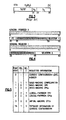
- the function code determining the operation is an unsigned binary integer in bit positions 32-35 of general register 0 and is as follows: Function Code Information Requested : 0 Current-configuration-level number 1 Information about level 1 (the basic machine) 2 Information about level 2 (a logical partition) 3 Information about level 3 (a virtual machine) 4-14 None; codes are reserved 15 Current-configuration-level information
- the level of the configuration executing the program is called the current level.
- the configuration level specified by a nonzero function code is called the specified level.
- the function code is called invalid, the condition code is set to 3, and no other action (including checking) is performed.
- SYSIB system-information block
- the SYSIB is 4K bytes and must begin at a 4K-byte boundary; otherwise, a specification exception may be recognized, depending on selector 1 and selector 2 and on whether access exceptions are recognized due to references to the SYSIB.
- Selector 1 can have values as follows: Selector 1 Information Requested 0 None; selector is reserved 1 Information about the configuration level specified by the function code 2 Information about one or more CPUs in the specified configuration level 3 - 255 None; selectors are reserved
- selector 2 can have values as follows: Selector 2 when Selector 1 Is 1 Information Requested 0 None; selector is reserved 1 Information about the specified configuration level 2 Topology information about the specified configuration level 3-65,535 None; selectors are reserved
- selector 2 can have values as follows: Selector 2 when Selector 1 Is 2 Information Requested 0 None; selector is reserved 1 Information about the CPU executing the program in the specified configuration level 2 Information about all CPUs in the specified configuration level 3-65,535 None; selectors are reserved
- the condition code is set to 3.
- the function code is nonzero, the combination is valid, the requested information is available, and there is no exception, the requested information is stored in a system-information block (SYSIB) at the second-operand address.
- SYSIB system-information block
- SYSIB may be fetched before it is stored.
- a SYSIB may be identified in references by means of "SYSIB fc.s1.s2,” where “fc,” “s1,” and “s2" are the values of a function code, selector 1, and selector 2, respectively.
- the configuration refers to the configuration level specified by the function code (the configuration level about which information is requested).
- SYSIB 1.1.1 has the format shown in FIG. 6 , where the fields have the following meanings:
- SYSIB 1.2.1 has the format shown in FIG. 7 where the fields have the following meaning:
- the format field in byte 0 of word 0 determines the format of the SYSIB.
- SYSIB 1.2.2 has a format-0 layout as shown in FIG. 8 .
- SYSIB 1.2.2 has a format-1 layout as shown in FIG. 9 .
- Byte 0 of word 0 contains an 8-bit unsigned binary integer that specifies the format of SYSIB 1.2.2.
- Word 7 contains a 32-bit unsigned binary integer that, when not zero, specifies a secondary capability that may be applied to certain types of CPUs in the configuration.
- the integer is used as an indication of the capability of a CPU relative to the capability of other CPU models, and also relative to the capability of other CPU types within a model.
- the capability value applies to each of the CPUs of one or more applicable CPU types in the configuration. That is, all CPUs in the configuration of an applicable type or types have the same capability. When the value is zero, all CPUs of any CPU type in the configuration have the same capability, as specified by the CPU capability.
- the secondary CPU capability may or may not be the same value as the CPU-capability value.
- the multiprocessing-CPU-capability-adjustment factors are also applicable to CPUs whose capability is specified by the secondary CPU capability.
- the word contains a 32-bit unsigned binary integer (I) in the range 0 ⁇ I ⁇ 2 23 that specifies the capability of one of the CPUs in the configuration. If bits 0-8 of word 8 are nonzero, the word contains a 32-bit binary floating point short-format number instead of a 32-bit unsigned binary integer. Regardless of encoding, a lower value indicates a proportionally higher CPU capacity. Beyond that, there is no formal description of the algorithm used to generate this value. The value is used as an indication of the capability of the CPU relative to the capability of other CPU models. The capability value applies to each of the non-secondary CPUs in the configuration. That is, all non-secondary CPUs in the configuration have the same capability.
- Bytes 0 and 1 of word 9 contain a 16-bit unsigned binary integer that specifies the total number of CPUs in the configuration. This number includes all CPUs in the configured state, the standby state, or the reserved state.
- Bytes 2 and 3 of word 9 contain a 16-bit unsigned binary integer that specifies the number of CPUs that are in the configured state. A CPU is in the configured state when it is in the configuration and available to be used to execute programs.
- Bytes 0 and 1 of word 10 contain a 16-bit unsigned binary integer that specifies the number of CPUs that are in the standby state.
- a CPU is in the standby state when it is in the configuration, is not available to be used to execute programs, and can be made available by issuing instructions to place it in the configured state.
- Bytes 2 and 3 of word 10 contain a 16-bit unsigned binary integer that specifies the number of CPUs that are in the reserved state.
- a CPU is in the reserved state when it is in the configuration, is not available to be used to execute programs, and cannot be made available by issuing instructions to place it in the configured state. (It may be possible to place a reserved CPU in the standby or configured state by means of manual actions.)
- the SYSIB contains a series of contiguous two-byte fields, each containing a 16-bit unsigned binary integer used to form an adjustment factor (fraction) for the value contained in the CPU-capability field.
- a fraction is developed by using the value (V) of the first two-byte field according to one of the following methods:
- each two-byte field is then developed by dividing the contents of a two byte field by the indicated denominator.
- the number of adjustment-factor fields is one less than the number of CPUs specified in the total-CPU count field.
- the adjustment-factor fields correspond to configurations with increasing numbers of CPUs in the configured state.
- the first adjustment-factor field corresponds to a configuration with two CPUs in the configured state.
- Each successive adjustment-factor field corresponds to a configuration with a number of CPUs in the configured state that is one more than that for the preceding field.
- the word When the format field has a value of one, if bits 0-8 of word N are zero, the word contains a 32-bit unsigned binary integer (I) in the range 0 ⁇ I ⁇ 2 23 that specifies the announced capability of one of the CPUs in the configuration. If bits 0-8 of word N are nonzero, the word contains a 32-bit binary floating point short-format number instead of a 32-bit unsigned binary integer. Regardless of encoding, a lower value indicates a proportionally higher CPU capacity. Beyond that, there is no formal description of the algorithm used to generate this value. The value is used as an indication of the announced capability of the CPU relative to the announced capability of other CPU models. The alternate-capability value applies to each of the CPUs in the configuration. That is, all CPUs in the configuration have the same alternate capability.
- the SYSIB contains a series of contiguous two-byte fields, each containing a 16-bit unsigned binary integer used to form an adjustment factor (fraction) for the value contained in the alternate- CPU-capability field.
- a fraction is developed by using the value (V) of the first two-byte field according to one of the following methods:
- each two-byte field is then developed by dividing the contents of a two byte field by the indicated denominator.
- the number of alternate-adjustment-factor fields is one less than the number of CPUs specified in the total-CPU-count field.
- the alternate-adjustment-factor fields correspond to configurations with increasing numbers of CPUs in the configured state.
- the first alternate-adjustment-factor field corresponds to a configuration with two CPUs in the configured state.
- Each successive alternate-adjustment-factor field corresponds to a configuration with a number of CPUs in the configured state that is one more than that for the preceding field.
- SYSIB 15.1.2 has the format shown in FIG. 10 .
- the fields have the meanings as follows:
- the topology is a structured list of entries where an entry defines one or more CPUs or else is involved with the nesting structure.
- the following illustrates the meaning of the magnitude fields:
- the value of the nesting level is 2
- Mag1 and Mag2 are the only non-zero magnitude fields
- the number of container-type TLEs stored does not exceed the Mag2 value
- the number of CPU-type TLEs stored within each container does not exceed the Mag1 value.
- the Mag3-6 bytes similarly become used (proceeding in a right-to-left direction) when the value of the nesting level falls in the range 3-6.
- MNest Byte 3 of word 2 specifies the nesting level of the topology to which the configuration may be extended while continuing to allow the guest program to survive.
- the maximum MNest value is six; the minimum is one. If MNest is one, there is no actual TLE nesting structure, Mag1 is the only non-zero field in the Mag1-6 range, and only CPU-type TLEs are represented in the topology list.
- the MNest value indicates the number of non-zero magnitude values beginning with the magnitude field at byte of word 2 (Mag1), proceeding left when MNest is greater than one, and with the remaining magnitude fields stored as zeros.
- MNest is the maximum possible nesting. No dynamic configuration change exceeds this limit.
- Topology List Words of FIG. 10 in the range 4 through N-1 specify a list of one or more topology-list entries (TLE).
- TLE topology-list entries
- Each TLE is an eight-byte or sixteen-byte field; thus N is an even number of words, and a corollary is that a TLE always starts on a doubleword boundary.
- Topology-List Entries The first TLE in the topology list begins at a nesting level equal to MNest-1.
- the entire topology list represents the configuration of the issuer of the STSI instruction specifying SYSIB 15.1.2; no outermost container TLE entry is used as it would be redundant with the entire list, and the entire configuration. There-fore, the highest nesting level may have more than a single peer container.
- FIGs. 11 and 12 illustrate the types of TLEs, wherein fields have the following definitions:
- TLE nesting level Byte 0 of word 0 specifies the TLE nesting level. NL Meaning 0
- the TLE is a CPU-type TLE. 1-5
- the TLE is a container-type TLE.
- the first container-type TLE stored in a topology list or a parent container has a container-ID in the range 1-255. If sibling containers exist within the same parent, they proceed in an ascending order of container IDs, that may or may not be consecutive, to a maximum value of 255. 06-FF Reserved.
- Sibling TLEs have the same value of nesting level which is equivalent to either the value of the nesting level minus one of the immediate parent TLE, or the value of MNest minus one, because the immediate parent is the topology list rather than a TLE.
- Byte of word 1 of a container-type TLE specifies an 8-bit unsigned non-zero binary integer whose value is the identifier of the container.
- the container ID for a TLE is unique within the same parent container.
- Bit 5 of word 1 of a CPU-type TLE when one, indicates that the one or more CPUs represented by the TLE are dedicated.
- D is zero, the one or more CPUs of the TLE are not dedicated.
- Bits 6-7 of word 1 of a CPU-type TLE specify the polarization value and, when polarization is vertical, the degree of vertical polarization also called entitlement (high, medium, low) of the corresponding CPU(s) represented by the TLE.
- entitlement high, medium, low
- Polarization is only significant in a logical and virtual multiprocessing configuration that uses shared host processors and addresses how the resource assigned to a configuration is applied across the CPUs of the configuration.
- horizontal polarization is in effect, each CPU of a configuration is guaranteed approximately the same amount of resource.
- vertical polarization is in effect, CPUs of a configuration are classified into three levels of resource entitlement: high, medium, and low.
- Both subsystem reset and successful execution of the SIGP set-architecture order specifying ESA/390 mode place a configuration and all of its CPUs into horizontal polarization.
- the CPUs immediately affected are those that are in the configured state.
- a dedicated CPU is either horizontally or vertically polarized.
- entitlement is always high.
- PP is either 00 binary or 11 binary.
- Byte 1 of word 1 of a CPU-type TLE specifies an 8-bit unsigned binary integer whose value is the CPU type of the one or more CPUs represented by the TLE.
- the CPU-type value specifies either a primary-CPU type or any one of the possible secondary-CPU types.
- Bytes 2-3 of word 1 of a CPU-type TLE specify a 16-bit unsigned binary integer whose value is the CPU address of the first CPU in the range of CPUs represented by the CPU mask, and whose presence is represented by the value of bit position 0 in the CPU mask.
- a CPU-address origin is evenly divisible by 64. The value of a CPU-address origin is the same as that stored by the STORE CPU ADDRESS (STAP) instruction when executed on the CPU represented by bit position 0 in the CPU mask.
- Words 2-3 of a CPU-type TLE specify a 64-bit mask where each bit position represents a CPU.
- the value of the CPU-address origin field plus a bit position in the CPU mask equals the CPU address for the corresponding CPU.
- a CPU mask bit is zero, the corresponding CPU is not represented by the TLE.
- the CPU is either not in the configuration or else must be represented by another CPU-type TLE.
- a CPU mask bit is one, the corresponding CPU has the modifier-attribute values specified by the TLE, is in the topology of the configuration, and is not present in any other TLE of the topology.
- CPU 79 is in the configuration and has the CPU type, polarization, entitlement, and dedication as specified by the TLE.
- the modifier attributes that apply to a CPU-type TLE are CPU type, polarization, entitlement, and dedication. Polarization and entitlement (for vertical polarization) are taken as a single attribute, albeit with four possible values (horizontal, vertical-high, vertical-medium, and vertical-low).
- a single CPU TLE is sufficient to represent as many as 64 CPUs that all have the same modifier- attribute values.
- a separate sibling CPU TLE is stored for each CPU-address origin, as necessary, in ascending order of CPU-address origin.
- Each such TLE stored has at least one CPU represented.
- the collection of one or more such CPU TLEs is called a CPU-TLE set.
- a separate CPU-TLE set is stored for each, in descending order of polarization value and degree (vertical high, medium, low, then horizontal).
- all polarization CPU-TLE sets of a given CPU type are stored before the next CPU-TLE set of the next CPU type.
- a container-type TLE is located at nesting levels in the range 1-5.
- a CPU-type TLE is located at nesting level 0.
- the number of sibling container-type TLEs in a topology list or a given parent container does not exceed the value of the magnitude byte (Mag2-6) of the nesting level corresponding to the siblings.
- the number of CPUs represented by the one or more CPU-type TLEs of the parent container does not exceed the value of the Mag1 magnitude byte.
- the content of a TLE is defined as follows:
- a possible examination process of a topology list is described. Before an examination of a topology list is begun, the current-TLE pointer is initialized to reference the first or top TLE in the topology list, the prior-TLE pointer is initialized to null, and then TLEs are examined in a top-to-bottom order.
- the current-TLE pointer is advanced by incrementing the current-TLE pointer by the size of the current TLE to which it points.
- a container-type TLE is advanced by adding eight to the current-TLE pointer.
- a CPU-type TLE is advanced by adding sixteen to the current-TLE pointer. The process of advancing the current-TLE pointer includes saving its value as the prior-TLE pointer just before it is incremented. TLE examination is not performed if the topology list has no TLEs.
- the examination process is outlined in the following steps:
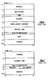
- a computer system comprises two physical frames (Frame 1 and Frame 2).
- Each frame contains two logic boards (Board 1 and Board 2), main storage (Memory), and I/O adapters (I/O Channels 1 and I/O Channels 2) for communicating with peripheral devices and networks.
- Each Board contains two multi-chip modules (Mod 1, Mod 2, Mod 3 and Mod 4).
- Each multi-chip module contains two processors (CPU1, CPU2, CPU3, CPU4, CPU5, CPU6 CPU7 and CPU8).
- Each module also contains a level-2 Cache (Cache 1, Cache 2, Cache 3 and Cache 4).
- Each processor Central Processing Unit or CPU
- TLB Translation-Lookaside-Buffer
- FIGS. 17 , 18 and 19 the components of the computer system are assigned to "containers" according to proximity.
- Each module is assigned to inner-most containers 6, 7, 8 and 9 as the CPUs of each module are in most close proximity to each other. Since the modules are packaged on boards, the modules of the respective boards are assigned to next level containers 4 and 5. The next higher proximity grouping is the Frame.
- the boards of a frame are assigned to a container representing the frame (containers 2 and 3). The whole system is represented by container 1.
- CPUs may be shared between operating systems as previously discussed. Therefore, if a logical partition was assigned 3 logical CPUs, each logical CPU assigned to 20% of each of three real CPUs, the partition would perform best if the 3 real CPUs were in closest proximity to each other as communication between CPUs and CPU resources (cache and memory for example) would perform best. In our example, CPU1 and CPU2 in a partition would experience less thrashing of cache lines in Cache 1 than if the two CPUs were CPU1 and CPU8.
- a partition is created including CPU1, CPU2 and CPU3.
- a program operating in the partition issues a STSI instruction and a SYSIB 15.1.2 ( FIG. 10 ) table is returned to the program.
- partition comprises container 6 and container 7 and therefore there are two levels of nesting.
- the SYSIB table values are:
- the MNest field is set to 4 indicating that the topology includes 4 levels of nesting, which is an absolute maximum nesting for the model, and may or may not be fully exploited on any arbitrary topology list, depending on resource assignment to the guest configuration issuing STSI, and how resources are assigned to other guest configurations of the system.
- the Mag1 field is set to 2 indicating 2 CPUs are available at the most primitive first level.
- the Mag2 field is set to 2 indicating that 2 second level (Module) containers are available.
- the Mag3 field is set to 2 indicating 2 third level (Boards) are available.
- the Mag4 field is set to 2 indicating 2 fourth level (Frames) are available.
- the program has a representation of the physical topology based on the container and CPU TLE's returned.
- a Perform Topology Function (PTF) instruction preferably comprises an opcode and a register field R1 identifying a first operand.
- the contents of the general register identified by R1 specify a function code in bit positions 56-63, as illustrated in Figure 14 .
- the defined function codes are as follows: FC Meaning 0 Request horizontal polarization. 1 Request vertical polarization. 2 Check topology-change status.
- Undefined function codes in the range 0-255 are reserved for future extensions.
- condition code 2 Upon completion, if condition code 2 is set, a reason code is stored in bit positions 48-55 of general register R1. Bits 16-23 and 28-31 of the instruction are ignored.
- Completion of the process is asynchronous with respect to execution of the instruction and may or may not be completed when execution of the instruction completes.
- a process is initiated to place all CPUs in the configuration into vertical polarization. Completion of the process is asynchronous with respect to execution of the instruction and may or may not be completed when execution of the instruction completes.
- a topology change is any alteration such that the contents of a SYSIB 15.1.2 would be different from the contents of the SYSIB 15.1.2 prior to the topology change.
- a topology-change-report-pending condition is created when a topology-change process completes.
- a topology-change-report-pending condition is cleared for the configuration when any of the following is performed:
- the new support discussed here addresses the true start of having zSeries OS software become aware of the topology of the machine, presented as a logical partition topology, to then provide affinity dispatching with regards to CPU placement in the CEC book structure.
- logical processors would have high, medium or low polarity.
- Polarity describes the amount of physical processor share vertical logical processors are entitled to.
- Customers define weights for logical partitions which effectively defines the amount of physical processor cycles each logical partition in a machine is entitled to.
- Polarity is measured by the ratio of a logical partition's current weight to the number of logical processors configured to the logical partition.
- High polarity processors have close to 100% CPU share.
- Medium Polarity processors have >0 to 99% shares and low polarity processors have 0% share (or very close to it).
- High polarity logical CPs will be assigned a physical processor to run on very similar to dedicated CPs but the shared high polarity CP can still give up the physical resource and allow other shared CPs to use its excess cycles. The key here then becomes that software sees the logical topology and tries to exploit the highly polarized logical CPs for its work queues.
- a customer configures a three-way processor with 2 logical partitions, each with 2 logical processors and each with a weight of 50. If the first logical partition defined itself as vertical, it would have 1 high and 1 medium polarity logical CP.
- a logical partition when a logical partition chooses to run in vertical mode, the entire logical partition runs in vertical mode. This includes all of its secondary processors such as zAAPs (IFAs) and/or zIIPs. It is the responsibility of the customer to define weights to all of the processor types for these logical partitions that will achieve the desired level of vertical processing for each type.
- IFAs zAAPs
- zIIPs It is the responsibility of the customer to define weights to all of the processor types for these logical partitions that will achieve the desired level of vertical processing for each type.
- a topology must be assigned to a logical partition when it is first activated and then any changes in the nodal topology assigned to a logical partition must result in the logical partition being notified.
- the results of the nodal topology must be kept in a convenient new data structure to allow easier queries by the new STSI processing as well as limiting processing as best as possible when configuration changes are made. This new structure also allows for topology change processing completing in multiple steps with the required serialization for each step without introducing inconsistent views of the topology to the logical partition.
- the polarization assignments are made from lowest online logical CP address of the cp type to highest in the order of (1) all vertical highs, (2) all vertical mediums, and (3) all vertical lows.
- the order in which this is done is arbitrary and other orders of selection are possible.
- a summary of a logical partition's topology is kept current in this block by the nodal assignment routines.
- the data in this block is ordered in such a way that STSI processing can make one pass of the entire structure to create the logical partition topology response to the program, preserving the order and separation of CPU entries as required by architecture.
- a second working area, TOP_WORKING, is included for use in updating the topology.
- a 2 bit encoding of partition polarization can be tracked for each logical processor to reflect its polarization. Grouping this with a 1-bit indication of dedication allows a complete polarity picture for a logical processor in 3-bits:
- each container is essentially a node with a nesting level of 1 and includes CPU type TLE(S) that each has a nesting level of 0.
- the CPU TLEs are ordered by CPU type followed by their classification. Vertical partitions have four classifications (vertical dedicated, vertical high shared, vertical medium shared, & vertical low shared) and horizontal partitions have two classifications (dedicated & shared).
- the following steps illustrate a use case for how a STSI 15.1.2 is handled after all the upfront checks have validated the instruction input.
- the nesting value is 1, followed by 48 reserved bits.
- the last bits are the node ID which is the index in topbk of the current node we are processing.
- the nesting level is 0, followed by 24 reserved bits.
- the next 8 bits include the dedicated bit and the polarization bit. If the partition is currently vertical, fill in the polarization value and dedicated bit as follows:
- the CPU Type the next value to be filled in the CPU-TLE is just the index of the second array within topcpumask in topbk. (0 - GP, 2 - IFA, 3 - IFL, 4 - ICF, 1 is currently unused).
- Multiprocessor Topology-Change-Report Pending If the configuration-topology facility is installed and enabled (ECB.7 is one), and the SCA address for the guest CPU is nonzero, bit position 0 is used to remember the topology-change-report-pending condition for the configuration. The reset state of topology change-report-pending is zero.
- the invention described herein is not limited to topology of processors. It can be appreciated that the basic component of the invention could advantageously apply to components other than CPUs, including, but not limited to co-processors, Caches, TLBs, internal data paths, data path buffers, distributed memory and I/O communications adapters for example.
Landscapes
- Engineering & Computer Science (AREA)
- Software Systems (AREA)
- Theoretical Computer Science (AREA)
- Physics & Mathematics (AREA)
- General Engineering & Computer Science (AREA)
- General Physics & Mathematics (AREA)
- Computer Networks & Wireless Communication (AREA)
- Signal Processing (AREA)
- Memory System Of A Hierarchy Structure (AREA)
- Mobile Radio Communication Systems (AREA)
- Hardware Redundancy (AREA)
- Multi Processors (AREA)
- Management, Administration, Business Operations System, And Electronic Commerce (AREA)
- Devices For Executing Special Programs (AREA)
- Two-Way Televisions, Distribution Of Moving Picture Or The Like (AREA)
- Stored Programmes (AREA)
- Executing Machine-Instructions (AREA)
Priority Applications (2)
| Application Number | Priority Date | Filing Date | Title |
|---|---|---|---|
| SI200930190T SI2290539T1 (sl) | 2008-01-11 | 2009-01-12 | Odkritje virtualne topologije raäśunalniĺ ke konfiguracije |
| PL10184363T PL2290539T3 (pl) | 2008-01-11 | 2009-01-12 | Wykrywanie topologii wirtualnego środowiska konfiguracji komputerowej |
Applications Claiming Priority (2)
| Application Number | Priority Date | Filing Date | Title |
|---|---|---|---|
| US11/972,802 US7734900B2 (en) | 2008-01-11 | 2008-01-11 | Computer configuration virtual topology discovery and instruction therefore |
| EP20090701347 EP2223214B1 (fr) | 2008-01-11 | 2009-01-12 | Découverte de topologie virtuelle de configuration d'ordinateur |
Related Parent Applications (1)
| Application Number | Title | Priority Date | Filing Date |
|---|---|---|---|
| EP09701347.8 Division | 2009-01-12 |
Publications (2)
| Publication Number | Publication Date |
|---|---|
| EP2290539A1 true EP2290539A1 (fr) | 2011-03-02 |
| EP2290539B1 EP2290539B1 (fr) | 2012-01-04 |
Family
ID=40851709
Family Applications (2)
| Application Number | Title | Priority Date | Filing Date |
|---|---|---|---|
| EP20100184363 Active EP2290539B1 (fr) | 2008-01-11 | 2009-01-12 | Découverte de topologie virtuelle de configuration d'ordinateur |
| EP20090701347 Active EP2223214B1 (fr) | 2008-01-11 | 2009-01-12 | Découverte de topologie virtuelle de configuration d'ordinateur |
Family Applications After (1)
| Application Number | Title | Priority Date | Filing Date |
|---|---|---|---|
| EP20090701347 Active EP2223214B1 (fr) | 2008-01-11 | 2009-01-12 | Découverte de topologie virtuelle de configuration d'ordinateur |
Country Status (13)
| Country | Link |
|---|---|
| US (4) | US7734900B2 (fr) |
| EP (2) | EP2290539B1 (fr) |
| JP (1) | JP4768083B2 (fr) |
| KR (1) | KR101231557B1 (fr) |
| CN (1) | CN101911018B (fr) |
| AT (2) | ATE540355T1 (fr) |
| CY (1) | CY1112463T1 (fr) |
| DK (2) | DK2223214T3 (fr) |
| ES (2) | ES2368684T3 (fr) |
| PL (2) | PL2290539T3 (fr) |
| PT (2) | PT2290539E (fr) |
| SI (2) | SI2290539T1 (fr) |
| WO (1) | WO2009087232A2 (fr) |
Cited By (3)
| Publication number | Priority date | Publication date | Assignee | Title |
|---|---|---|---|---|
| US9582295B2 (en) | 2014-03-18 | 2017-02-28 | International Business Machines Corporation | Architectural mode configuration |
| US9588774B2 (en) | 2014-03-18 | 2017-03-07 | International Business Machines Corporation | Common boot sequence for control utility able to be initialized in multiple architectures |
| US9916185B2 (en) | 2014-03-18 | 2018-03-13 | International Business Machines Corporation | Managing processing associated with selected architectural facilities |
Families Citing this family (33)
| Publication number | Priority date | Publication date | Assignee | Title |
|---|---|---|---|---|
| US8122230B2 (en) * | 2007-12-28 | 2012-02-21 | Intel Corporation | Using a processor identification instruction to provide multi-level processor topology information |
| US7739434B2 (en) | 2008-01-11 | 2010-06-15 | International Business Machines Corporation | Performing a configuration virtual topology change and instruction therefore |
| US7734900B2 (en) * | 2008-01-11 | 2010-06-08 | International Business Machines Corporation | Computer configuration virtual topology discovery and instruction therefore |
| US9032101B1 (en) | 2008-12-10 | 2015-05-12 | Nvidia Corporation | Chipset support for binding and migrating hardware devices among heterogeneous processing units |
| US9015446B2 (en) * | 2008-12-10 | 2015-04-21 | Nvidia Corporation | Chipset support for non-uniform memory access among heterogeneous processing units |
| US8171176B2 (en) * | 2010-08-31 | 2012-05-01 | Lsi Corporation | Method for selective replication of physical devices on a virtual self-configuring zoning expander |
| JP5354108B2 (ja) * | 2010-09-01 | 2013-11-27 | 富士通株式会社 | 情報処理プログラム、情報処理装置及び情報処理方法 |
| US20120131154A1 (en) * | 2010-11-23 | 2012-05-24 | Wulf Kruempelmann | Synchronous Transport of Business Configuration Data in a Distributed Computing System Environment |
| WO2012083012A1 (fr) * | 2010-12-15 | 2012-06-21 | Advanced Micro Devices, Inc. | Découverte de dispositifs et signalisation de topologie dans un système d'architecture combinée cpu/gpu |
| DE102011107169A1 (de) * | 2011-07-13 | 2013-01-17 | Kuka Roboter Gmbh | Steuerung eines Roboter |
| US9639815B2 (en) | 2011-07-14 | 2017-05-02 | International Business Machines Corporation | Managing processes in an enterprise intelligence (‘EI’) assembly of an EI framework |
| US8566345B2 (en) | 2011-07-14 | 2013-10-22 | International Business Machines Corporation | Enterprise intelligence (‘EI’) reporting in an EI framework |
| US9646278B2 (en) | 2011-07-14 | 2017-05-09 | International Business Machines Corporation | Decomposing a process model in an enterprise intelligence (‘EI’) framework |
| US9659266B2 (en) | 2011-07-14 | 2017-05-23 | International Business Machines Corporation | Enterprise intelligence (‘EI’) management in an EI framework |
| JP5836042B2 (ja) * | 2011-10-04 | 2015-12-24 | 株式会社日立製作所 | 管理サーバプログラム |
| US9069598B2 (en) * | 2012-01-06 | 2015-06-30 | International Business Machines Corporation | Providing logical partions with hardware-thread specific information reflective of exclusive use of a processor core |
| US9292318B2 (en) * | 2012-11-26 | 2016-03-22 | International Business Machines Corporation | Initiating software applications requiring different processor architectures in respective isolated execution environment of an operating system |
| WO2014141419A1 (fr) * | 2013-03-14 | 2014-09-18 | 株式会社日立製作所 | Système d'ordinateur virtuel et procédé de planification |
| US9804846B2 (en) | 2014-03-27 | 2017-10-31 | International Business Machines Corporation | Thread context preservation in a multithreading computer system |
| US9218185B2 (en) * | 2014-03-27 | 2015-12-22 | International Business Machines Corporation | Multithreading capability information retrieval |
| US9354883B2 (en) | 2014-03-27 | 2016-05-31 | International Business Machines Corporation | Dynamic enablement of multithreading |
| US10102004B2 (en) | 2014-03-27 | 2018-10-16 | International Business Machines Corporation | Hardware counters to track utilization in a multithreading computer system |
| US9921848B2 (en) | 2014-03-27 | 2018-03-20 | International Business Machines Corporation | Address expansion and contraction in a multithreading computer system |
| US9417876B2 (en) | 2014-03-27 | 2016-08-16 | International Business Machines Corporation | Thread context restoration in a multithreading computer system |
| US9594660B2 (en) | 2014-03-27 | 2017-03-14 | International Business Machines Corporation | Multithreading computer system and program product for executing a query instruction for idle time accumulation among cores |
| KR102269452B1 (ko) | 2014-09-18 | 2021-06-28 | 인텔 코포레이션 | 컨텐츠 변환 없는 컴퓨팅 디바이스에서의 다중 운영 체제 환경들의 지원 |
| CN104539684B (zh) * | 2014-12-23 | 2018-07-06 | 广州亦云信息技术有限公司 | 一种用户机器资源抽取整合方法及系统 |
| CN107301034A (zh) * | 2017-08-09 | 2017-10-27 | 葛松芬 | 一种并行处理器阵列结构 |
| US10956358B2 (en) * | 2017-11-21 | 2021-03-23 | Microsoft Technology Licensing, Llc | Composite pipeline framework to combine multiple processors |
| US11042398B2 (en) | 2018-07-09 | 2021-06-22 | Samsung Electronics Co., Ltd. | System and method for guest operating system using containers |
| US11256531B2 (en) * | 2019-06-20 | 2022-02-22 | International Business Machines Corporation | Isolating physical processors during optimization of VM placement |
| CN110990054B (zh) * | 2019-12-03 | 2023-03-21 | 北京明略软件系统有限公司 | 一种开源框架的配置处理方法及装置 |
| CN114489771A (zh) * | 2022-01-28 | 2022-05-13 | 苏州浪潮智能科技有限公司 | 一种Python的配置监控和响应方法、装置、设备及可读介质 |
Citations (9)
| Publication number | Priority date | Publication date | Assignee | Title |
|---|---|---|---|---|
| US5551013A (en) | 1994-06-03 | 1996-08-27 | International Business Machines Corporation | Multiprocessor for hardware emulation |
| EP0730226A2 (fr) * | 1995-03-03 | 1996-09-04 | Hal Computer Systems, Inc. | Support en hardware pour l'émulation rapide d'instructions non implémentées |
| US5574873A (en) | 1993-05-07 | 1996-11-12 | Apple Computer, Inc. | Decoding guest instruction to directly access emulation routines that emulate the guest instructions |
| US5790825A (en) | 1995-11-08 | 1998-08-04 | Apple Computer, Inc. | Method for emulating guest instructions on a host computer through dynamic recompilation of host instructions |
| US6009261A (en) | 1997-12-16 | 1999-12-28 | International Business Machines Corporation | Preprocessing of stored target routines for emulating incompatible instructions on a target processor |
| US6308255B1 (en) | 1998-05-26 | 2001-10-23 | Advanced Micro Devices, Inc. | Symmetrical multiprocessing bus and chipset used for coprocessor support allowing non-native code to run in a system |
| US6463582B1 (en) | 1998-10-21 | 2002-10-08 | Fujitsu Limited | Dynamic optimizing object code translator for architecture emulation and dynamic optimizing object code translation method |
| EP1674987A2 (fr) | 2004-12-21 | 2006-06-28 | Microsoft Corporation | Systèmes et procédés dýexposition de la topologie dýun processeur pour des machines virtuelles |
| US20070203943A1 (en) * | 2006-02-28 | 2007-08-30 | Ingo Adlung | Method and apparatus for generating unique identifiers for logical partitions |
Family Cites Families (28)
| Publication number | Priority date | Publication date | Assignee | Title |
|---|---|---|---|---|
| US3825895A (en) * | 1973-05-14 | 1974-07-23 | Amdahl Corp | Operand comparator |
| US3982229A (en) * | 1975-01-08 | 1976-09-21 | Bell Telephone Laboratories, Incorporated | Combinational logic arrangement |
| US4713750A (en) * | 1983-03-31 | 1987-12-15 | Fairchild Camera & Instrument Corporation | Microprocessor with compact mapped programmable logic array |
| US4569016A (en) * | 1983-06-30 | 1986-02-04 | International Business Machines Corporation | Mechanism for implementing one machine cycle executable mask and rotate instructions in a primitive instruction set computing system |
| US4578750A (en) * | 1983-08-24 | 1986-03-25 | Amdahl Corporation | Code determination using half-adder based operand comparator |
| IT1179386B (it) * | 1984-07-05 | 1987-09-16 | Silvano Bellapadrona | Sospensione oleopneumatica per veicoli in genere, in particolare per motociclette |
| US5113523A (en) * | 1985-05-06 | 1992-05-12 | Ncube Corporation | High performance computer system |
| JPS6382513A (ja) * | 1986-09-26 | 1988-04-13 | Toshiba Corp | バレルシフタ |
| US5859994A (en) * | 1992-08-10 | 1999-01-12 | Intel Corporation | Apparatus and method for modifying instruction length decoding in a computer processor |
| US6067613A (en) * | 1993-11-30 | 2000-05-23 | Texas Instruments Incorporated | Rotation register for orthogonal data transformation |
| US5748950A (en) * | 1994-09-20 | 1998-05-05 | Intel Corporation | Method and apparatus for providing an optimized compare-and-branch instruction |
| EP0730220A3 (fr) * | 1995-03-03 | 1997-01-08 | Hal Computer Systems Inc | Procédé et dispositif pour l'exécution rapide d'instructions de tranchement |
| US5732242A (en) * | 1995-03-24 | 1998-03-24 | Silicon Graphics, Inc. | Consistently specifying way destinations through prefetching hints |
| JP3790607B2 (ja) | 1997-06-16 | 2006-06-28 | 松下電器産業株式会社 | Vliwプロセッサ |
| US6223256B1 (en) * | 1997-07-22 | 2001-04-24 | Hewlett-Packard Company | Computer cache memory with classes and dynamic selection of replacement algorithms |
| US6112293A (en) * | 1997-11-17 | 2000-08-29 | Advanced Micro Devices, Inc. | Processor configured to generate lookahead results from operand collapse unit and for inhibiting receipt/execution of the first instruction based on the lookahead result |
| JP3872343B2 (ja) | 1999-09-28 | 2007-01-24 | インターナショナル・ビジネス・マシーンズ・コーポレーション | コンピュータ環境におけるワークロード管理 |
| US6446197B1 (en) * | 1999-10-01 | 2002-09-03 | Hitachi, Ltd. | Two modes for executing branch instructions of different lengths and use of branch control instruction and register set loaded with target instructions |
| US6763327B1 (en) * | 2000-02-17 | 2004-07-13 | Tensilica, Inc. | Abstraction of configurable processor functionality for operating systems portability |
| US6738895B1 (en) * | 2000-08-31 | 2004-05-18 | Micron Technology, Inc. | Method and system for substantially registerless processing |
| US7165101B2 (en) * | 2001-12-03 | 2007-01-16 | Sun Microsystems, Inc. | Transparent optimization of network traffic in distributed systems |
| US7493480B2 (en) * | 2002-07-18 | 2009-02-17 | International Business Machines Corporation | Method and apparatus for prefetching branch history information |
| US7140021B2 (en) * | 2002-09-13 | 2006-11-21 | Microsoft Corporation | Dynamic TCP partitioning |
| US7337442B2 (en) * | 2002-12-03 | 2008-02-26 | Microsoft Corporation | Methods and systems for cooperative scheduling of hardware resource elements |
| WO2005022384A1 (fr) | 2003-08-28 | 2005-03-10 | Mips Technologies, Inc. | Instruction pour declenchement de flux d'instructions concurrents dans un microprocesseur a traitement multifiliere |
| US8335810B2 (en) * | 2006-01-31 | 2012-12-18 | Qualcomm Incorporated | Register-based shifts for a unidirectional rotator |
| US7734900B2 (en) * | 2008-01-11 | 2010-06-08 | International Business Machines Corporation | Computer configuration virtual topology discovery and instruction therefore |
| US8352950B2 (en) * | 2008-01-11 | 2013-01-08 | International Business Machines Corporation | Algorithm to share physical processors to maximize processor cache usage and topologies |
-
2008
- 2008-01-11 US US11/972,802 patent/US7734900B2/en active Active
-
2009
- 2009-01-12 CN CN2009801017609A patent/CN101911018B/zh active Active
- 2009-01-12 PL PL10184363T patent/PL2290539T3/pl unknown
- 2009-01-12 ES ES09701347T patent/ES2368684T3/es active Active
- 2009-01-12 SI SI200930190T patent/SI2290539T1/sl unknown
- 2009-01-12 PT PT10184363T patent/PT2290539E/pt unknown
- 2009-01-12 EP EP20100184363 patent/EP2290539B1/fr active Active
- 2009-01-12 JP JP2010541796A patent/JP4768083B2/ja active Active
- 2009-01-12 ES ES10184363T patent/ES2380450T3/es active Active
- 2009-01-12 DK DK09701347T patent/DK2223214T3/da active
- 2009-01-12 PL PL09701347T patent/PL2223214T3/pl unknown
- 2009-01-12 EP EP20090701347 patent/EP2223214B1/fr active Active
- 2009-01-12 KR KR1020107015025A patent/KR101231557B1/ko active IP Right Grant
- 2009-01-12 AT AT10184363T patent/ATE540355T1/de active
- 2009-01-12 WO PCT/EP2009/050250 patent/WO2009087232A2/fr active Application Filing
- 2009-01-12 DK DK10184363T patent/DK2290539T3/da active
- 2009-01-12 PT PT09701347T patent/PT2223214E/pt unknown
- 2009-01-12 SI SI200930066T patent/SI2223214T1/sl unknown
- 2009-01-12 AT AT09701347T patent/ATE514130T1/de active
-
2010
- 2010-05-13 US US12/779,232 patent/US7984275B2/en active Active
-
2011
- 2011-06-15 US US13/160,536 patent/US8832689B2/en active Active
- 2011-09-21 CY CY20111100912T patent/CY1112463T1/el unknown
-
2014
- 2014-09-05 US US14/478,247 patent/US9137120B2/en active Active
Patent Citations (9)
| Publication number | Priority date | Publication date | Assignee | Title |
|---|---|---|---|---|
| US5574873A (en) | 1993-05-07 | 1996-11-12 | Apple Computer, Inc. | Decoding guest instruction to directly access emulation routines that emulate the guest instructions |
| US5551013A (en) | 1994-06-03 | 1996-08-27 | International Business Machines Corporation | Multiprocessor for hardware emulation |
| EP0730226A2 (fr) * | 1995-03-03 | 1996-09-04 | Hal Computer Systems, Inc. | Support en hardware pour l'émulation rapide d'instructions non implémentées |
| US5790825A (en) | 1995-11-08 | 1998-08-04 | Apple Computer, Inc. | Method for emulating guest instructions on a host computer through dynamic recompilation of host instructions |
| US6009261A (en) | 1997-12-16 | 1999-12-28 | International Business Machines Corporation | Preprocessing of stored target routines for emulating incompatible instructions on a target processor |
| US6308255B1 (en) | 1998-05-26 | 2001-10-23 | Advanced Micro Devices, Inc. | Symmetrical multiprocessing bus and chipset used for coprocessor support allowing non-native code to run in a system |
| US6463582B1 (en) | 1998-10-21 | 2002-10-08 | Fujitsu Limited | Dynamic optimizing object code translator for architecture emulation and dynamic optimizing object code translation method |
| EP1674987A2 (fr) | 2004-12-21 | 2006-06-28 | Microsoft Corporation | Systèmes et procédés dýexposition de la topologie dýun processeur pour des machines virtuelles |
| US20070203943A1 (en) * | 2006-02-28 | 2007-08-30 | Ingo Adlung | Method and apparatus for generating unique identifiers for logical partitions |
Non-Patent Citations (1)
| Title |
|---|
| PERRETTA R F: "z/Architecture overview - part 2", MVS UPDATE, vol. 196, 1 January 2003 (2003-01-01), pages 1 - 74, XP002616948, Retrieved from the Internet <URL:http://www.cbttape.org/xephon/xephonm/mvs0301.pdf> [retrieved on 20100117] * |
Cited By (10)
| Publication number | Priority date | Publication date | Assignee | Title |
|---|---|---|---|---|
| US9582295B2 (en) | 2014-03-18 | 2017-02-28 | International Business Machines Corporation | Architectural mode configuration |
| US9588774B2 (en) | 2014-03-18 | 2017-03-07 | International Business Machines Corporation | Common boot sequence for control utility able to be initialized in multiple architectures |
| US9594576B2 (en) | 2014-03-18 | 2017-03-14 | International Business Machines Corporation | Architectural mode configuration |
| US9600292B2 (en) | 2014-03-18 | 2017-03-21 | International Business Machines Corporation | Common boot sequence for control utility able to be initialized in multiple architectures |
| US9916185B2 (en) | 2014-03-18 | 2018-03-13 | International Business Machines Corporation | Managing processing associated with selected architectural facilities |
| US9916186B2 (en) | 2014-03-18 | 2018-03-13 | International Business Machines Corporation | Managing processing associated with selected architectural facilities |
| US10545772B2 (en) | 2014-03-18 | 2020-01-28 | International Business Machines Corporation | Architectural mode configuration |
| US10552175B2 (en) | 2014-03-18 | 2020-02-04 | International Business Machines Corporation | Architectural mode configuration |
| US10747583B2 (en) | 2014-03-18 | 2020-08-18 | International Business Machines Corporation | Managing processing associated with selected architectural facilities |
| US10747582B2 (en) | 2014-03-18 | 2020-08-18 | International Business Machines Corporation | Managing processing associated with selected architectural facilities |
Also Published As
| Publication number | Publication date |
|---|---|
| DK2290539T3 (da) | 2012-02-06 |
| EP2223214B1 (fr) | 2011-06-22 |
| PL2223214T3 (pl) | 2011-11-30 |
| PT2290539E (pt) | 2012-02-15 |
| US9137120B2 (en) | 2015-09-15 |
| JP2011509477A (ja) | 2011-03-24 |
| US8832689B2 (en) | 2014-09-09 |
| US20100223448A1 (en) | 2010-09-02 |
| DK2223214T3 (da) | 2011-08-01 |
| ATE514130T1 (de) | 2011-07-15 |
| CN101911018B (zh) | 2013-08-28 |
| US7984275B2 (en) | 2011-07-19 |
| US20110246752A1 (en) | 2011-10-06 |
| US20090182979A1 (en) | 2009-07-16 |
| CY1112463T1 (el) | 2015-12-09 |
| PT2223214E (pt) | 2011-09-19 |
| ES2380450T3 (es) | 2012-05-11 |
| ATE540355T1 (de) | 2012-01-15 |
| CN101911018A (zh) | 2010-12-08 |
| WO2009087232A3 (fr) | 2009-11-05 |
| EP2223214A2 (fr) | 2010-09-01 |
| EP2290539B1 (fr) | 2012-01-04 |
| KR20100106462A (ko) | 2010-10-01 |
| PL2290539T3 (pl) | 2012-06-29 |
| ES2368684T3 (es) | 2011-11-21 |
| US7734900B2 (en) | 2010-06-08 |
| KR101231557B1 (ko) | 2013-02-08 |
| US20150026680A1 (en) | 2015-01-22 |
| SI2290539T1 (sl) | 2012-04-30 |
| WO2009087232A2 (fr) | 2009-07-16 |
| JP4768083B2 (ja) | 2011-09-07 |
| SI2223214T1 (sl) | 2011-10-28 |
Similar Documents
| Publication | Publication Date | Title |
|---|---|---|
| US10621007B2 (en) | Execution of an instruction for performing a configuration virtual topology change | |
| US9137120B2 (en) | Emulating execution of an instruction for discovering virtual topology of a logical partitioned computer system | |
| US7234037B2 (en) | Memory mapped Input/Output operations | |
| US7146482B2 (en) | Memory mapped input/output emulation | |
| WO2012034793A1 (fr) | Accès par adresse réelle dans un coprocesseur exécutant des opérations pour le compte d'un processus non privilégié |
Legal Events
| Date | Code | Title | Description |
|---|---|---|---|
| PUAI | Public reference made under article 153(3) epc to a published international application that has entered the european phase |
Free format text: ORIGINAL CODE: 0009012 |
|
| 17P | Request for examination filed |
Effective date: 20100930 |
|
| AC | Divisional application: reference to earlier application |
Ref document number: 2223214 Country of ref document: EP Kind code of ref document: P |
|
| AK | Designated contracting states |
Kind code of ref document: A1 Designated state(s): AT BE BG CH CY CZ DE DK EE ES FI FR GB GR HR HU IE IS IT LI LT LU LV MC MK MT NL NO PL PT RO SE SI SK TR |
|
| AX | Request for extension of the european patent |
Extension state: AL BA RS |
|
| 17Q | First examination report despatched |
Effective date: 20110630 |
|
| GRAP | Despatch of communication of intention to grant a patent |
Free format text: ORIGINAL CODE: EPIDOSNIGR1 |
|
| RIC1 | Information provided on ipc code assigned before grant |
Ipc: G06F 9/30 20060101ALI20110902BHEP Ipc: G06F 9/50 20060101ALI20110902BHEP Ipc: G06F 9/455 20060101AFI20110902BHEP |
|
| GRAS | Grant fee paid |
Free format text: ORIGINAL CODE: EPIDOSNIGR3 |
|
| GRAA | (expected) grant |
Free format text: ORIGINAL CODE: 0009210 |
|
| AC | Divisional application: reference to earlier application |
Ref document number: 2223214 Country of ref document: EP Kind code of ref document: P |
|
| AK | Designated contracting states |
Kind code of ref document: B1 Designated state(s): AT BE BG CH CY CZ DE DK EE ES FI FR GB GR HR HU IE IS IT LI LT LU LV MC MK MT NL NO PL PT RO SE SI SK TR |
|
| REG | Reference to a national code |
Ref country code: GB Ref legal event code: FG4D |
|
| REG | Reference to a national code |
Ref country code: CH Ref legal event code: EP |
|
| REG | Reference to a national code |
Ref country code: AT Ref legal event code: REF Ref document number: 540355 Country of ref document: AT Kind code of ref document: T Effective date: 20120115 |
|
| REG | Reference to a national code |
Ref country code: IE Ref legal event code: FG4D |
|
| REG | Reference to a national code |
Ref country code: DK Ref legal event code: T3 |
|
| REG | Reference to a national code |
Ref country code: PT Ref legal event code: SC4A Free format text: AVAILABILITY OF NATIONAL TRANSLATION Effective date: 20120207 |
|
| REG | Reference to a national code |
Ref country code: DE Ref legal event code: R096 Ref document number: 602009004632 Country of ref document: DE Effective date: 20120308 |
|
| REG | Reference to a national code |
Ref country code: RO Ref legal event code: EPE |
|
| REG | Reference to a national code |
Ref country code: CH Ref legal event code: NV Representative=s name: IBM RESEARCH GMBH ZURICH RESEARCH LABORATORY INTEL |
|
| REG | Reference to a national code |
Ref country code: NL Ref legal event code: T3 |
|
| REG | Reference to a national code |
Ref country code: SE Ref legal event code: TRGR |
|
| REG | Reference to a national code |
Ref country code: ES Ref legal event code: FG2A Ref document number: 2380450 Country of ref document: ES Kind code of ref document: T3 Effective date: 20120511 |
|
| REG | Reference to a national code |
Ref country code: NO Ref legal event code: T2 Effective date: 20120104 |
|
| REG | Reference to a national code |
Ref country code: GR Ref legal event code: EP Ref document number: 20120400543 Country of ref document: GR Effective date: 20120417 |
|
| REG | Reference to a national code |
Ref country code: SK Ref legal event code: T3 Ref document number: E 11311 Country of ref document: SK |
|
| REG | Reference to a national code |
Ref country code: EE Ref legal event code: FG4A Ref document number: E006620 Country of ref document: EE Effective date: 20120403 |
|
| REG | Reference to a national code |
Ref country code: HU Ref legal event code: AG4A Ref document number: E012974 Country of ref document: HU |
|
| REG | Reference to a national code |
Ref country code: PL Ref legal event code: T3 |
|
| PG25 | Lapsed in a contracting state [announced via postgrant information from national office to epo] |
Ref country code: HR Free format text: LAPSE BECAUSE OF FAILURE TO SUBMIT A TRANSLATION OF THE DESCRIPTION OR TO PAY THE FEE WITHIN THE PRESCRIBED TIME-LIMIT Effective date: 20120104 |
|
| PG25 | Lapsed in a contracting state [announced via postgrant information from national office to epo] |
Ref country code: MC Free format text: LAPSE BECAUSE OF NON-PAYMENT OF DUE FEES Effective date: 20120131 |
|
| PG25 | Lapsed in a contracting state [announced via postgrant information from national office to epo] |
Ref country code: CY Free format text: LAPSE BECAUSE OF NON-PAYMENT OF DUE FEES Effective date: 20120112 |
|
| PLBE | No opposition filed within time limit |
Free format text: ORIGINAL CODE: 0009261 |
|
| STAA | Information on the status of an ep patent application or granted ep patent |
Free format text: STATUS: NO OPPOSITION FILED WITHIN TIME LIMIT |
|
| 26N | No opposition filed |
Effective date: 20121005 |
|
| REG | Reference to a national code |
Ref country code: DE Ref legal event code: R097 Ref document number: 602009004632 Country of ref document: DE Effective date: 20121005 |
|
| PG25 | Lapsed in a contracting state [announced via postgrant information from national office to epo] |
Ref country code: MK Free format text: LAPSE BECAUSE OF FAILURE TO SUBMIT A TRANSLATION OF THE DESCRIPTION OR TO PAY THE FEE WITHIN THE PRESCRIBED TIME-LIMIT Effective date: 20120104 |
|
| PG25 | Lapsed in a contracting state [announced via postgrant information from national office to epo] |
Ref country code: TR Free format text: LAPSE BECAUSE OF FAILURE TO SUBMIT A TRANSLATION OF THE DESCRIPTION OR TO PAY THE FEE WITHIN THE PRESCRIBED TIME-LIMIT Effective date: 20120104 |
|
| REG | Reference to a national code |
Ref country code: FR Ref legal event code: PLFP Year of fee payment: 8 |
|
| REG | Reference to a national code |
Ref country code: FR Ref legal event code: PLFP Year of fee payment: 9 |
|
| REG | Reference to a national code |
Ref country code: FR Ref legal event code: PLFP Year of fee payment: 10 |
|
| REG | Reference to a national code |
Ref country code: DE Ref legal event code: R082 Ref document number: 602009004632 Country of ref document: DE Representative=s name: KUISMA, SIRPA, FI |
|
| PGFP | Annual fee paid to national office [announced via postgrant information from national office to epo] |
Ref country code: SK Payment date: 20231219 Year of fee payment: 16 |
|
| PGFP | Annual fee paid to national office [announced via postgrant information from national office to epo] |
Ref country code: LT Payment date: 20231219 Year of fee payment: 16 Ref country code: CZ Payment date: 20231219 Year of fee payment: 16 |
|
| PGFP | Annual fee paid to national office [announced via postgrant information from national office to epo] |
Ref country code: LU Payment date: 20240112 Year of fee payment: 16 |
|
| PGFP | Annual fee paid to national office [announced via postgrant information from national office to epo] |
Ref country code: GR Payment date: 20240131 Year of fee payment: 16 |
|
| PGFP | Annual fee paid to national office [announced via postgrant information from national office to epo] |
Ref country code: IS Payment date: 20240124 Year of fee payment: 16 |
|
| PGFP | Annual fee paid to national office [announced via postgrant information from national office to epo] |
Ref country code: NL Payment date: 20240126 Year of fee payment: 16 Ref country code: IE Payment date: 20240110 Year of fee payment: 16 Ref country code: ES Payment date: 20240208 Year of fee payment: 16 |
|
| PGFP | Annual fee paid to national office [announced via postgrant information from national office to epo] |
Ref country code: AT Payment date: 20240110 Year of fee payment: 16 |
|
| PGFP | Annual fee paid to national office [announced via postgrant information from national office to epo] |
Ref country code: RO Payment date: 20240112 Year of fee payment: 16 Ref country code: HU Payment date: 20231218 Year of fee payment: 16 Ref country code: FI Payment date: 20240110 Year of fee payment: 16 Ref country code: EE Payment date: 20240124 Year of fee payment: 16 Ref country code: DE Payment date: 20240216 Year of fee payment: 16 Ref country code: BG Payment date: 20240125 Year of fee payment: 16 Ref country code: PT Payment date: 20240108 Year of fee payment: 16 Ref country code: GB Payment date: 20240129 Year of fee payment: 16 Ref country code: CH Payment date: 20240202 Year of fee payment: 16 |
|
| PGFP | Annual fee paid to national office [announced via postgrant information from national office to epo] |
Ref country code: SI Payment date: 20240108 Year of fee payment: 16 |
|
| PGFP | Annual fee paid to national office [announced via postgrant information from national office to epo] |
Ref country code: SE Payment date: 20240117 Year of fee payment: 16 Ref country code: PL Payment date: 20240108 Year of fee payment: 16 Ref country code: NO Payment date: 20240110 Year of fee payment: 16 Ref country code: MT Payment date: 20240125 Year of fee payment: 16 Ref country code: LV Payment date: 20240123 Year of fee payment: 16 Ref country code: IT Payment date: 20240105 Year of fee payment: 16 Ref country code: FR Payment date: 20240119 Year of fee payment: 16 Ref country code: DK Payment date: 20240115 Year of fee payment: 16 Ref country code: BE Payment date: 20240112 Year of fee payment: 16 |