EP2290514A2 - Mobiles Endgerät und Steuerungsverfahren dafür - Google Patents
Mobiles Endgerät und Steuerungsverfahren dafür Download PDFInfo
- Publication number
- EP2290514A2 EP2290514A2 EP10008815A EP10008815A EP2290514A2 EP 2290514 A2 EP2290514 A2 EP 2290514A2 EP 10008815 A EP10008815 A EP 10008815A EP 10008815 A EP10008815 A EP 10008815A EP 2290514 A2 EP2290514 A2 EP 2290514A2
- Authority
- EP
- European Patent Office
- Prior art keywords
- mobile terminal
- touchscreen
- touch
- prescribed
- locked state
- Prior art date
- Legal status (The legal status is an assumption and is not a legal conclusion. Google has not performed a legal analysis and makes no representation as to the accuracy of the status listed.)
- Withdrawn
Links
- 238000000034 method Methods 0.000 title claims abstract description 20
- 230000006870 function Effects 0.000 description 15
- 238000004891 communication Methods 0.000 description 13
- 230000000694 effects Effects 0.000 description 12
- 238000010586 diagram Methods 0.000 description 8
- 238000010295 mobile communication Methods 0.000 description 6
- 230000009471 action Effects 0.000 description 5
- 238000012545 processing Methods 0.000 description 5
- 230000005236 sound signal Effects 0.000 description 5
- 230000008901 benefit Effects 0.000 description 4
- 238000005516 engineering process Methods 0.000 description 4
- 230000003287 optical effect Effects 0.000 description 4
- 239000004973 liquid crystal related substance Substances 0.000 description 3
- 230000008569 process Effects 0.000 description 3
- 238000012546 transfer Methods 0.000 description 3
- 230000008878 coupling Effects 0.000 description 2
- 238000010168 coupling process Methods 0.000 description 2
- 238000005859 coupling reaction Methods 0.000 description 2
- 238000013500 data storage Methods 0.000 description 2
- 230000006872 improvement Effects 0.000 description 2
- 238000002347 injection Methods 0.000 description 2
- 239000007924 injection Substances 0.000 description 2
- 230000007246 mechanism Effects 0.000 description 2
- 238000012986 modification Methods 0.000 description 2
- 230000004048 modification Effects 0.000 description 2
- 229910001220 stainless steel Inorganic materials 0.000 description 2
- 239000010935 stainless steel Substances 0.000 description 2
- 230000003068 static effect Effects 0.000 description 2
- 239000010936 titanium Substances 0.000 description 2
- 230000000007 visual effect Effects 0.000 description 2
- RTAQQCXQSZGOHL-UHFFFAOYSA-N Titanium Chemical compound [Ti] RTAQQCXQSZGOHL-UHFFFAOYSA-N 0.000 description 1
- 230000001133 acceleration Effects 0.000 description 1
- 238000013459 approach Methods 0.000 description 1
- 238000003491 array Methods 0.000 description 1
- 230000005540 biological transmission Effects 0.000 description 1
- 230000008859 change Effects 0.000 description 1
- 230000001186 cumulative effect Effects 0.000 description 1
- 230000005684 electric field Effects 0.000 description 1
- 230000005672 electromagnetic field Effects 0.000 description 1
- 239000010408 film Substances 0.000 description 1
- 239000005338 frosted glass Substances 0.000 description 1
- 238000001746 injection moulding Methods 0.000 description 1
- 238000005259 measurement Methods 0.000 description 1
- 239000002184 metal Substances 0.000 description 1
- 229910052751 metal Inorganic materials 0.000 description 1
- 210000003205 muscle Anatomy 0.000 description 1
- 230000006855 networking Effects 0.000 description 1
- 230000010355 oscillation Effects 0.000 description 1
- 230000000630 rising effect Effects 0.000 description 1
- 239000000126 substance Substances 0.000 description 1
- 229920003002 synthetic resin Polymers 0.000 description 1
- 239000000057 synthetic resin Substances 0.000 description 1
- 239000010409 thin film Substances 0.000 description 1
- 229910052719 titanium Inorganic materials 0.000 description 1
- 230000007704 transition Effects 0.000 description 1
Images


Classifications
-
- G—PHYSICS
- G06—COMPUTING; CALCULATING OR COUNTING
- G06F—ELECTRIC DIGITAL DATA PROCESSING
- G06F3/00—Input arrangements for transferring data to be processed into a form capable of being handled by the computer; Output arrangements for transferring data from processing unit to output unit, e.g. interface arrangements
- G06F3/01—Input arrangements or combined input and output arrangements for interaction between user and computer
- G06F3/048—Interaction techniques based on graphical user interfaces [GUI]
- G06F3/0487—Interaction techniques based on graphical user interfaces [GUI] using specific features provided by the input device, e.g. functions controlled by the rotation of a mouse with dual sensing arrangements, or of the nature of the input device, e.g. tap gestures based on pressure sensed by a digitiser
- G06F3/0488—Interaction techniques based on graphical user interfaces [GUI] using specific features provided by the input device, e.g. functions controlled by the rotation of a mouse with dual sensing arrangements, or of the nature of the input device, e.g. tap gestures based on pressure sensed by a digitiser using a touch-screen or digitiser, e.g. input of commands through traced gestures
- G06F3/04883—Interaction techniques based on graphical user interfaces [GUI] using specific features provided by the input device, e.g. functions controlled by the rotation of a mouse with dual sensing arrangements, or of the nature of the input device, e.g. tap gestures based on pressure sensed by a digitiser using a touch-screen or digitiser, e.g. input of commands through traced gestures for inputting data by handwriting, e.g. gesture or text
-
- G—PHYSICS
- G06—COMPUTING; CALCULATING OR COUNTING
- G06F—ELECTRIC DIGITAL DATA PROCESSING
- G06F1/00—Details not covered by groups G06F3/00 - G06F13/00 and G06F21/00
- G06F1/16—Constructional details or arrangements
- G06F1/1613—Constructional details or arrangements for portable computers
- G06F1/1626—Constructional details or arrangements for portable computers with a single-body enclosure integrating a flat display, e.g. Personal Digital Assistants [PDAs]
-
- G—PHYSICS
- G06—COMPUTING; CALCULATING OR COUNTING
- G06F—ELECTRIC DIGITAL DATA PROCESSING
- G06F1/00—Details not covered by groups G06F3/00 - G06F13/00 and G06F21/00
- G06F1/16—Constructional details or arrangements
- G06F1/1613—Constructional details or arrangements for portable computers
- G06F1/1633—Constructional details or arrangements of portable computers not specific to the type of enclosures covered by groups G06F1/1615 - G06F1/1626
- G06F1/1637—Details related to the display arrangement, including those related to the mounting of the display in the housing
- G06F1/1643—Details related to the display arrangement, including those related to the mounting of the display in the housing the display being associated to a digitizer, e.g. laptops that can be used as penpads
-
- G—PHYSICS
- G06—COMPUTING; CALCULATING OR COUNTING
- G06F—ELECTRIC DIGITAL DATA PROCESSING
- G06F3/00—Input arrangements for transferring data to be processed into a form capable of being handled by the computer; Output arrangements for transferring data from processing unit to output unit, e.g. interface arrangements
- G06F3/01—Input arrangements or combined input and output arrangements for interaction between user and computer
- G06F3/03—Arrangements for converting the position or the displacement of a member into a coded form
- G06F3/041—Digitisers, e.g. for touch screens or touch pads, characterised by the transducing means
-
- G—PHYSICS
- G06—COMPUTING; CALCULATING OR COUNTING
- G06F—ELECTRIC DIGITAL DATA PROCESSING
- G06F3/00—Input arrangements for transferring data to be processed into a form capable of being handled by the computer; Output arrangements for transferring data from processing unit to output unit, e.g. interface arrangements
- G06F3/01—Input arrangements or combined input and output arrangements for interaction between user and computer
- G06F3/048—Interaction techniques based on graphical user interfaces [GUI]
- G06F3/0481—Interaction techniques based on graphical user interfaces [GUI] based on specific properties of the displayed interaction object or a metaphor-based environment, e.g. interaction with desktop elements like windows or icons, or assisted by a cursor's changing behaviour or appearance
-
- G—PHYSICS
- G06—COMPUTING; CALCULATING OR COUNTING
- G06F—ELECTRIC DIGITAL DATA PROCESSING
- G06F3/00—Input arrangements for transferring data to be processed into a form capable of being handled by the computer; Output arrangements for transferring data from processing unit to output unit, e.g. interface arrangements
- G06F3/01—Input arrangements or combined input and output arrangements for interaction between user and computer
- G06F3/048—Interaction techniques based on graphical user interfaces [GUI]
- G06F3/0484—Interaction techniques based on graphical user interfaces [GUI] for the control of specific functions or operations, e.g. selecting or manipulating an object, an image or a displayed text element, setting a parameter value or selecting a range
- G06F3/0486—Drag-and-drop
-
- G—PHYSICS
- G06—COMPUTING; CALCULATING OR COUNTING
- G06F—ELECTRIC DIGITAL DATA PROCESSING
- G06F3/00—Input arrangements for transferring data to be processed into a form capable of being handled by the computer; Output arrangements for transferring data from processing unit to output unit, e.g. interface arrangements
- G06F3/14—Digital output to display device ; Cooperation and interconnection of the display device with other functional units
-
- H—ELECTRICITY
- H04—ELECTRIC COMMUNICATION TECHNIQUE
- H04M—TELEPHONIC COMMUNICATION
- H04M1/00—Substation equipment, e.g. for use by subscribers
- H04M1/66—Substation equipment, e.g. for use by subscribers with means for preventing unauthorised or fraudulent calling
- H04M1/667—Preventing unauthorised calls from a telephone set
- H04M1/67—Preventing unauthorised calls from a telephone set by electronic means
-
- H—ELECTRICITY
- H04—ELECTRIC COMMUNICATION TECHNIQUE
- H04M—TELEPHONIC COMMUNICATION
- H04M1/00—Substation equipment, e.g. for use by subscribers
- H04M1/72—Mobile telephones; Cordless telephones, i.e. devices for establishing wireless links to base stations without route selection
- H04M1/724—User interfaces specially adapted for cordless or mobile telephones
- H04M1/72403—User interfaces specially adapted for cordless or mobile telephones with means for local support of applications that increase the functionality
-
- H—ELECTRICITY
- H04—ELECTRIC COMMUNICATION TECHNIQUE
- H04M—TELEPHONIC COMMUNICATION
- H04M2250/00—Details of telephonic subscriber devices
- H04M2250/22—Details of telephonic subscriber devices including a touch pad, a touch sensor or a touch detector
Definitions
- the present invention relates to a mobile terminal, and more particularly, to a mobile terminal and controlling method thereof.
- the present invention is suitable for a wide scope of applications, it is particularly suitable for implementing a terminal to be used in further consideration of user's convenience.
- a mobile terminal is a device which may be configured to perform various functions. Examples of such functions include data and voice communications, capturing images and video via a camera, recording audio, playing music files and outputting music via a speaker system, and displaying images and video on a display. Some terminals include additional functionality which supports game playing, while other terminals are also configured as multimedia players. More recently, mobile terminals have been configured to receive broadcast and multicast signals which permit viewing of contents, such as videos and television programs.
- terminals can be classified into mobile terminals and stationary terminals according to a presence or non-presence of mobility. And, the mobile terminals can be further classified into handheld terminals and vehicle mount terminals according to availability for hand-carry.
- touchscreen type mobile terminals tend to be globally introduced.
- This touchscreen type mobile terminal enters a locked state to prevent an incorrect touch from being inputted by a terminal user if a user input is not performed for predetermined duration.
- a method of facilitating a terminal user to conveniently use a specific function is necessary. And, the demand for this method keeps rising.
- the present invention is directed to a mobile terminal and controlling method thereof that substantially obviate one or more problems due to limitations and disadvantages of the related art.
- An object of the present invention is to provide a mobile terminal and controlling method thereof, by which a terminal user is facilitated to use a specific function of a mobile terminal in a locked state to prevent an incorrect touch input to a touchscreen provided to the mobile terminal.
- a mobile terminal includes a touchscreen, and a control unit configured to display a standby image on the touchscreen by image blurring when the mobile terminal is in a locked state, to release the locked state when a prescribed touch gesture is performed on the touchscreen, and to display the standby image by image deblurring when the lock state is released.
- a method of controlling a mobile terminal includes entering a terminal locked state, displaying a standby image on a touchscreen by image blurring, releasing the locked state if a prescribed touch gesture is performed on the touchscreen, and displaying the standby image by image deblurring.
- FIG. 1 is a block diagram of a mobile terminal according to one embodiment of the present invention.
- FIG. 2A is a front perspective diagram of a mobile terminal according to one embodiment of the present invention.
- FIG. 2B is a rear perspective diagram of a mobile terminal according to one embodiment of the present invention.
- FIG. 3 is a flowchart for a method of controlling a mobile terminal according to an embodiment of the present invention.
- FIGs. 4 to 9 are diagrams for display screens on which a method of controlling a mobile terminal according to an embodiment of the present invention is implemented.
- the present invention can be applicable to a various types of terminals.
- terminals include mobile as well as stationary terminals, such as mobile phones, user equipment, smart phones, DTV, computers, digital broadcast terminals, personal digital assistants, portable multimedia players (PMP) and navigators.
- PMP portable multimedia players
- FIG. 1 is a block diagram of a mobile terminal 100 in accordance with an embodiment of the present invention.
- FIG. 1 shows the mobile terminal 100 according to one embodiment of the present invention includes a wireless communication unit 110, an A/V (audio/video) input unit 120, a user input unit 130, a sensing unit 140, an output unit 150, a memory 160, an interface unit 170, a controller 180, a power supply unit 190 and the like.
- FIG. 1 shows the mobile terminal 100 having various components, but it is understood that implementing all of the illustrated components is not a requirement. Greater or fewer components may alternatively be implemented.
- the wireless communication unit 110 typically includes one or more components which permits wireless communication between the mobile terminal 100 and a wireless communication system or network within which the mobile terminal 100 is located.
- the wireless communication unit 110 can include a broadcast receiving module 111, a mobile communication module 112, a wireless internet module 113, a short-range communication module 114, a position-location module 115 and the like.
- the broadcast receiving module 111 receives a broadcast signal and/or broadcast associated information from an external broadcast managing server via a broadcast channel.
- the broadcast channel may include a satellite channel and a terrestrial channel.
- the broadcast managing server generally refers to a server which generates and transmits a broadcast signal and/or broadcast associated information or a server which is provided with a previously generated broadcast signal and/or broadcast associated information and then transmits the provided signal or information to a terminal.
- the broadcast signal may be implemented as a TV broadcast signal, a radio broadcast signal, and a data broadcast signal, among others. If desired, the broadcast signal may further include a broadcast signal combined with a TV or radio broadcast signal.
- At least two broadcast receiving modules 111 can be provided to the mobile terminal 100 in pursuit of simultaneous receptions of at least two broadcast channels or broadcast channel switching facilitation.
- the broadcast associated information includes information associated with a broadcast channel, a broadcast program, a broadcast service provider, etc. And, the broadcast associated information can be provided via a mobile communication network. In this case, the broadcast associated information can be received by the mobile communication module 112.
- broadcast associated information can be implemented in various forms.
- broadcast associated information may include an electronic program guide (EPG) of digital multimedia broadcasting (DMB) and electronic service guide (ESG) of digital video broadcast-handheld (DVB-H).
- EPG electronic program guide
- ESG electronic service guide
- DMB digital multimedia broadcasting
- DVB-H digital video broadcast-handheld
- the broadcast receiving module 111 may be configured to receive broadcast signals transmitted from various types of broadcast systems.
- broadcasting systems include digital multimedia broadcasting-terrestrial (DMB-T), digital multimedia broadcasting-satellite (DMB-S), digital video broadcast-handheld (DVB-H), DVB-CBMS, OMA-BCAST, the data broadcasting system known as media forward link only (MediaFLO®) and integrated services digital broadcast-terrestrial (ISDB-T).
- DMB-T digital multimedia broadcasting-terrestrial
- DMB-S digital multimedia broadcasting-satellite
- DVD-H digital video broadcast-handheld
- DVB-CBMS digital video broadcast-handheld
- OMA-BCAST the data broadcasting system known as media forward link only (MediaFLO®)
- ISDB-T integrated services digital broadcast-terrestrial
- the broadcast receiving module 111 can be configured suitable for other broadcasting systems as well as the above-explained digital broadcasting systems.
- the broadcast signal and/or broadcast associated information received by the broadcast receiving module 111 may be stored in a suitable device, such as a memory 160.
- the mobile communication module 112 transmits/receives wireless signals to/from one or more network entities (e.g., base station, external terminal, server, etc.). Such wireless signals may represent audio, video, and data according to text/multimedia message transceivings, among others.
- network entities e.g., base station, external terminal, server, etc.
- Such wireless signals may represent audio, video, and data according to text/multimedia message transceivings, among others.
- the wireless internet module 113 supports Internet access for the mobile terminal 100.
- This module may be internally or externally coupled to the mobile terminal 100.
- the wireless Internet technology can include WLAN(Wireless LAN) (Wi-Fi), Wibro (Wireless broadband), Wimax (World Interoperability for Microwave Access), HSDPA(High Speed Downlink Packet Access), etc.
- the short-range communication module 114 facilitates relatively short-range communications. Suitable technologies for implementing this module include radio frequency identification (RFID), infrared data association (IrDA), ultra-wideband (UWB), as well at the networking technologies commonly referred to as Bluetooth and ZigBee, to name a few.
- RFID radio frequency identification
- IrDA infrared data association
- UWB ultra-wideband
- the position-location module 115 identifies or otherwise obtains the location of the mobile terminal 100. If desired, this module may be implemented with a global positioning system (GPS) module.
- GPS global positioning system
- the audio/video (A/V) input unit 120 is configured to provide audio or video signal input to the mobile terminal 100.
- the A/V input unit 120 includes a camera 121 and a microphone 122.
- the camera 121 receives and processes image frames of still pictures or video, which are obtained by an image sensor in a video call mode or a photographing mode. And, the processed image frames can be displayed on the display 151.
- the image frames processed by the camera 121 can be stored in the memory 160 or can be externally transmitted via the wireless communication unit 110.
- at least two cameras 121 can be provided to the mobile terminal 100 according to environment of usage.
- the microphone 122 receives an external audio signal while the portable device is in a particular mode, such as phone call mode, recording mode and voice recognition. This audio signal is processed and converted into electric audio data. The processed audio data is transformed into a format transmittable to a mobile communication base station via the mobile communication module 112 in case of a call mode.
- the microphone 122 typically includes assorted noise removing algorithms to remove noise generated in the course of receiving the external audio signal.
- the user input unit 130 generates input data responsive to user manipulation of an associated input device or devices.
- Examples of such devices include a keypad, a dome switch, a touchpad (e.g., static pressure/capacitance), a jog wheel, a jog switch, etc.
- the sensing unit 140 provides sensing signals for controlling operations of the mobile terminal 100 using status measurements of various aspects of the mobile terminal. For instance, the sensing unit 140 may detect an open/close status of the mobile terminal 100, relative positioning of components (e.g., a display and keypad) of the mobile terminal 100, a change of position of the mobile terminal 100 or a component of the mobile terminal 100, a presence or absence of user contact with the mobile terminal 100, orientation or acceleration/deceleration of the mobile terminal 100. As an example, consider the mobile terminal 100 being configured as a slide-type mobile terminal. In this configuration, the sensing unit 140 may sense whether a sliding portion of the mobile terminal is open or closed. Other examples include the sensing unit 140 sensing the presence or absence of power provided by the power supply 190, the presence or absence of a coupling or other connection between the interface unit 170 and an external device. And, the sensing unit 140 can include a proximity sensor 141.
- components e.g., a display and keypad
- the output unit 150 generates outputs relevant to the senses of sight, hearing, touch and the like. And, the output unit 150 includes the display 151, an audio output module 152, an alarm unit 153, a haptic module 154, a projector module 155 and the like.
- the display 151 is typically implemented to visually display (output) information associated with the mobile terminal 100. For instance, if the mobile terminal is operating in a phone call mode, the display will generally provide a user interface (UI) or graphical user interface (GUI) which includes information associated with placing, conducting, and terminating a phone call. As another example, if the mobile terminal 100 is in a video call mode or a photographing mode, the display 151 may additionally or alternatively display images which are associated with these modes, the UI or the GUI.
- UI user interface
- GUI graphical user interface
- the display module 151 may be implemented using known display technologies including, for example, a liquid crystal display (LCD), a thin film transistor-liquid crystal display (TFT-LCD), an organic light-emitting diode display (OLED), a flexible display and a three-dimensional display.
- LCD liquid crystal display
- TFT-LCD thin film transistor-liquid crystal display
- OLED organic light-emitting diode display
- the mobile terminal 100 may include one or more of such displays.
- Some of the above displays can be implemented in a transparent or optical transmittive type, which can be named a transparent display.
- a transparent display there is TOLED (transparent OLED) or the like.
- a rear configuration of the display 151 can be implemented in the optical transmittive type as well. In this configuration, a user is able to see an object in rear of a terminal body via the area occupied by the display 151 of the terminal body.
- At least two displays 151 can be provided to the mobile terminal 100 in accordance with the implemented configuration of the mobile terminal 100.
- a plurality of displays can be arranged on a single face of the mobile terminal 100 in a manner of being spaced apart from each other or being built in one body.
- a plurality of displays can be arranged on different faces of the mobile terminal 100.
- the display 151 and a sensor for detecting a touch action configures a mutual layer structure (hereinafter called 'touchscreen')
- the touch sensor can be configured as a touch film, a touch sheet, a touchpad or the like.
- the touch sensor can be configured to convert a pressure applied to a specific portion of the display 151 or a variation of a capacitance generated from a specific portion of the display 151 to an electric input signal. Moreover, it is able to configure the touch sensor to detect a pressure of a touch as well as a touched position or size.
- a touch input is made to the touch sensor, signal(s) corresponding to the touch is transferred to a touch controller.
- the touch controller processes the signal(s) and then transfers the processed signal(s) to the controller 180. Therefore, the controller 180 is able to know whether a prescribed portion of the display 151 is touched.
- a proximity sensor (not shown in the drawing) can be provided to an internal area of the mobile terminal 100 enclosed by the touchscreen or around the touchscreen.
- the proximity sensor is the sensor that detects a presence or non-presence of an object approaching a prescribed detecting surface or an object existing around the proximity sensor using an electromagnetic field strength or infrared ray without mechanical contact.
- the proximity sensor has durability longer than that of a contact type sensor and also has utility wider than that of the contact type sensor.
- the proximity sensor can include one of a transmittive photoelectric sensor, a direct reflective photoelectric sensor, a mirror reflective photoelectric sensor, a radio frequency oscillation proximity sensor, an electrostatic capacity proximity sensor, a magnetic proximity sensor, an infrared proximity sensor and the like.
- the touchscreen includes the electrostatic capacity proximity sensor, it is configured to detect the proximity of a pointer using a variation of electric field according to the proximity of the pointer.
- the touchscreen can be classified as the proximity sensor.
- an action that a pointer approaches without contacting with the touchscreen to be recognized as located on the touchscreen is named 'proximity touch'.
- an action that a pointer actually touches the touchscreen is named 'contact touch'.
- the meaning of the position on the touchscreen proximity-touched by the pointer means the position of the pointer which vertically opposes the touchscreen when the pointer performs the proximity touch.
- the proximity sensor detects a proximity touch and a proximity touch pattern (e.g., a proximity touch distance, a proximity touch duration, a proximity touch position, a proximity touch shift state, etc.). And, information corresponding to the detected proximity touch action and the detected proximity touch pattern can be outputted to the touchscreen.
- a proximity touch and a proximity touch pattern e.g., a proximity touch distance, a proximity touch duration, a proximity touch position, a proximity touch shift state, etc.
- the audio output module 152 functions in various modes including a call-receiving mode, a call-placing mode, a recording mode, a voice recognition mode, a broadcast reception mode and the like to output audio data which is received from the wireless communication unit 110 or is stored in the memory 160. During operation, the audio output module 152 outputs audio relating to a particular function (e.g., call received, message received, etc.). The audio output module 152 is often implemented using one or more speakers, buzzers, other audio producing devices, and combinations thereof.
- the alarm unit 153 is output a signal for announcing the occurrence of a particular event associated with the mobile terminal 100.
- Typical events include a call received event, a message received event and a touch input received event.
- the alarm unit 153 is able to output a signal for announcing the event occurrence by way of vibration as well as video or audio signal.
- the video or audio signal can be outputted via the display 151 or the audio output unit 152.
- the display 151 or the audio output module 152 can be regarded as a part of the alarm unit 153.
- the haptic module 154 generates various tactile effects that can be sensed by a user. Vibration is a representative one of the tactile effects generated by the haptic module 154. Strength and pattern of the vibration generated by the haptic module 154 are controllable. For instance, different vibrations can be outputted in a manner of being synthesized together or can be outputted in sequence.
- the haptic module 154 is able to generate various tactile effects as well as the vibration. For instance, the haptic module 154 generates the effect attributed to the arrangement of pins vertically moving against a contact skin surface, the effect attributed to the injection/suction power of air though an injection/suction hole, the effect attributed to the skim over a skin surface, the effect attributed to the contact with electrode, the effect attributed to the electrostatic force, the effect attributed to the representation of hold/cold sense using an endothermic or exothermic device and the like.
- the haptic module 154 can be implemented to enable a user to sense the tactile effect through a muscle sense of finger, arm or the like as well as to transfer the tactile effect through a direct contact.
- at least two haptic modules 154 can be provided to the mobile terminal 100 in accordance with the corresponding configuration type of the mobile terminal 100.
- the projector module 155 is the element for performing an image projector function using the mobile terminal 100. And, the projector module 155 is able to display an image, which is identical to or partially different at least from the image displayed on the display 151, on an external screen or wall according to a control signal of the controller 180.
- the projector module 155 can include a light source (not shown in the drawing) generating light (e.g., laser) for projecting an image externally, an image producing means (not shown in the drawing) for producing an image to output externally using the light generated from the light source, and a lens (not shown in the drawing) for enlarging to output the image externally in a predetermined focus distance.
- the projector module 155 can further include a device (not shown in the drawing) for adjusting an image projected direction by mechanically moving the lens or the whole module.
- the projector module 155 can be classified into a CRT (cathode ray tube) module, an LCD (liquid crystal display) module, a DLP (digital light processing) module or the like according to a device type of a display means.
- the DLP module is operated by the mechanism of enabling the light generated from the light source to reflect on a DMD (digital micro-mirror device) chip and can be advantageous for the downsizing of the projector module 151.
- the projector module 155 can be provided in a length direction of a lateral, front or backside direction of the mobile terminal 100. And, it is understood that the projector module 155 can be provided to any portion of the mobile terminal 100 according to the necessity thereof.
- the memory unit 160 is generally used to store various types of data to support the processing, control, and storage requirements of the mobile terminal 100. Examples of such data include program instructions for applications operating on the mobile terminal 100, contact data, phonebook data, messages, audio, still pictures, moving pictures, etc. And, a recent use history or a cumulative use frequency of each data (e.g., use frequency for each phonebook, each message or each multimedia) can be stored in the memory unit 160. Moreover, data for various patterns of vibration and/or sound outputted in case of a touch input to the touchscreen can be stored in the memory unit 160.
- Data for touch gestures corresponding to prescribed execution functions can be further stored in the memory unit 160. Therefore, if a specific one of the touch gestures is performed on the touchscreen, the execution function corresponding to the specific touch gesture can be executed in the mobile terminal 100. This will be explained later in this disclosure.
- the memory unit 160 may be implemented using any type or combination of suitable volatile and non-volatile memory or storage devices including hard disk, random access memory (RAM), static random access memory (SRAM), electrically erasable programmable read-only memory (EEPROM), erasable programmable read-only memory (EPROM), programmable read-only memory (PROM), read-only memory (ROM), magnetic memory, flash memory, magnetic or optical disk, multimedia card micro type memory, card-type memory (e.g., SD memory, XD memory, etc.), or other similar memory or data storage device.
- RAM random access memory
- SRAM static random access memory
- EEPROM electrically erasable programmable read-only memory
- EPROM erasable programmable read-only memory
- PROM programmable read-only memory
- ROM read-only memory
- magnetic memory flash memory
- flash memory magnetic or optical disk
- multimedia card micro type memory e.g., SD memory, XD memory, etc.
- multimedia card micro type memory e.g
- the interface unit 170 is often implemented to couple the mobile terminal 100 with external devices.
- the interface unit 170 receives data from the external devices or is supplied with the power and then transfers the data or power to the respective elements of the mobile terminal 100 or enables data within the mobile terminal 100 to be transferred to the external devices.
- the interface unit 170 may be configured using a wired/wireless headset port, an external charger port, a wired/wireless data port, a memory card port, a port for coupling to a device having an identity module, audio input/output ports, video input/output ports, an earphone port and/or the like.
- the identity module is the chip for storing various kinds of information for authenticating a use authority of the mobile terminal 100 and can include User Identify Module (UIM), Subscriber Identify Module (SIM), Universal Subscriber Identity Module (USIM) and/or the like.
- a device having the identity module (hereinafter called 'identity device') can be manufactured as a smart card. Therefore, the identity device is connectible to the mobile terminal 100 via the corresponding port.
- the interface unit 170 When the mobile terminal 110 is connected to an external cradle, the interface unit 170 becomes a passage for supplying the mobile terminal 100 with a power from the cradle or a passage for delivering various command signals inputted from the cradle by a user to the mobile terminal 100.
- Each of the various command signals inputted from the cradle or the power can operate as a signal enabling the mobile terminal 100 to recognize that it is correctly loaded in the cradle.
- the controller 180 typically controls the overall operations of the mobile terminal 100. For example, the controller 180 performs the control and processing associated with voice calls, data communications, video calls, etc.
- the controller 180 may include a multimedia module 181 that provides multimedia playback.
- the multimedia module 181 may be configured as part of the controller 180, or implemented as a separate component.
- controller 180 is able to perform a pattern recognizing process for recognizing a writing input and a picture drawing input carried out on the touchscreen as characters or images, respectively.
- the power supply unit 190 provides power required by the various components for the mobile terminal 100.
- the power may be internal power, external power, or combinations thereof.
- Various embodiments described herein may be implemented in a computer-readable medium using, for example, computer software, hardware, or some combination thereof.
- the embodiments described herein may be implemented within one or more application specific integrated circuits (ASICs), digital signal processors (DSPs), digital signal processing devices (DSPDs), programmable logic devices (PLDs), field programmable gate arrays (FPGAs), processors, controllers, micro-controllers, microprocessors, other electronic units designed to perform the functions described herein, or a selective combination thereof.
- ASICs application specific integrated circuits
- DSPs digital signal processors
- DSPDs digital signal processing devices
- PLDs programmable logic devices
- FPGAs field programmable gate arrays
- processors controllers, micro-controllers, microprocessors, other electronic units designed to perform the functions described herein, or a selective combination thereof.
- controller 180 may also be implemented by the controller 180.
- the embodiments described herein may be implemented with separate software modules, such as procedures and functions, each of which perform one or more of the functions and operations described herein.
- the software codes can be implemented with a software application written in any suitable programming language and may be stored in memory such as the memory 160, and executed by a controller or processor, such as the controller 180.
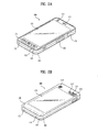
- FIG. 2A is a front perspective diagram of a mobile terminal according to one embodiment of the present invention.
- the mobile terminal 100 shown in the drawing has a bar type terminal body. Yet, the mobile terminal 100 may be implemented in a variety of different configurations. Examples of such configurations include folder-type, slide-type, rotational-type, swing-type and combinations thereof. For clarity, further disclosure will primarily relate to a bar-type mobile terminal 100. However such teachings apply equally to other types of mobile terminals.
- the mobile terminal 100 includes a case (casing, housing, cover, etc.) configuring an exterior thereof.
- the case can be divided into a front case 101 and a rear case 102.
- Various electric/electronic parts are loaded in a space provided between the front and rear cases 101 and 102.
- at least one middle case can be further provided between the front and rear cases 101 and 102 in addition.
- the cases 101 and 102 are formed by injection molding of synthetic resin or can be formed of metal substance such as stainless steel (STS), titanium (Ti) or the like for example.
- STS stainless steel
- Ti titanium
- a display 151, an audio output unit 152, a camera 121, user input units 130/131 and 132, a microphone 122, an interface 180 and the like can be provided to the terminal body, and more particularly, to the front case 101.
- the display 151 occupies most of a main face of the front case 101.
- the audio output unit 151 and the camera 121 are provided to an area adjacent to one of both end portions of the display 151, while the user input unit 131 and the microphone 122 are provided to another area adjacent to the other end portion of the display 151.
- the user input unit 132 and the interface 170 can be provided to lateral sides of the front and rear cases 101 and 102.
- the input unit 130 is manipulated to receive a command for controlling an operation of the terminal 100. And, the input unit 130 is able to include a plurality of manipulating units 131 and 132.
- the manipulating units 131 and 132 can be named a manipulating portion and may adopt any mechanism of a tactile manner that enables a user to perform a manipulation action by experiencing a tactile feeling.
- Content inputted by the first or second manipulating unit 131 or 132 can be diversely set. For instance, such a command as start, end, scroll and the like is inputted to the first manipulating unit 131. And, a command for a volume adjustment of sound outputted from the audio output unit 152, a command for a switching to a touch recognizing mode of the display 151 or the like can be inputted to the second manipulating unit 132.
- FIG. 2B is a perspective diagram of a backside of the terminal shown in FIG. 2A .
- a camera 121' can be additionally provided to a backside of the terminal body, and more particularly, to the rear case 102.
- the camera 121 has a photographing direction that is substantially opposite to that of the former camera 121 shown in FIG. 21A and may have pixels differing from those of the firmer camera 121.
- the former camera 121 has low pixels enough to capture and transmit a picture of user's face for a video call, while the latter camera 121' has high pixels for capturing a general subject for photography without transmitting the captured subject.
- each of the cameras 121 and 121' can be installed at the terminal body to be rotated or popped up.
- a flash 123 and a mirror 124 are additionally provided adjacent to the camera 121'.
- the flash 123 projects light toward a subject in case of photographing the subject using the camera 121'.
- the mirror 124 enables the user to view user's face reflected by the mirror 124.
- An additional audio output unit 152' can be provided to the backside of the terminal body.
- the additional audio output unit 152' is able to implement a stereo function together with the former audio output unit 152 shown in FIG. 2A and may be used for implementation of a speakerphone mode in talking over the terminal.
- a broadcast signal receiving antenna 124 can be additionally provided to the lateral side of the terminal body as well as an antenna for communication or the like.
- the antenna 124 constructing a portion of the broadcast receiving module 111 shown in FIG. 1 can be retractably provided to the terminal body.
- a power supply unit 190 for supplying a power to the terminal 100 is provided to the terminal body.
- the power supply unit 190 can be configured to be built within the terminal body.
- the power supply unit 190 can be configured to be detachably connected to the terminal body.
- a touchpad 135 for detecting a touch can be additionally provided to the rear case 102.
- the touchpad 135 can be configured in a light transmittive type like the display 151.
- the display 151 is configured to output visual information from its both faces, it is able to recognize the visual information via the touchpad 135 as well.
- the information outputted from both of the faces can be entirely controlled by the touchpad 135.
- a display is further provided to the touchpad 135 so that a touchscreen can be provided to the rear case 102 as well.
- the touchpad 135 is activated by interconnecting with the display 151 of the front case 101.
- the touchpad 135 can be provided in rear of the display 151 in parallel.
- the touchpad 135 can have a size equal to or smaller than that of the display 151.
- the display 151 includes a touchscreen. If the display 151 includes the touchscreen, it further facilitates the following embodiments to be implemented. In the following description, a display screen of the display 151 shall be indicated by a reference number 400.
- FIG. 3 is a flowchart for a method of controlling a mobile terminal according to an embodiment of the present invention
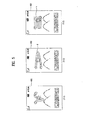
- FIGs. 4 to 9 are diagrams for display screens on which a method of controlling a mobile terminal according to an embodiment of the present invention is implemented.
- the mobile terminal 100 is in a standby mode and an image (hereinafter named 'standby image') of the standby mode is displayed on the touchscreen 400.
- 'standby image' an image
- at least one indicator 410 indicating an operational state of the mobile terminal 100
- a background image 420 and at least one menu icon 430 can exist. It is not necessary for all of the indicator 410, the background image 420 and the menu icon 430 to exist in the standby image. For instance, at least one of them may not be displayed on the standby image.
- an event may not occur during a prescribed time in the mobile terminal 100.
- this event may include at least one of a call signal reception, a message reception, a key signal input and a touch input.
- the mobile terminal 100 is able to enter a locked state [S31]. Once the mobile terminal 100 enters the locked state, any touch may not be recognized on the touchscreen except prescribed touch gestures explained in the following description.
- the standby image can be displayed on the touchscreen 400 in a manner of image blurring [S32].
- this image blurring may correspond to an image processing scheme of blurring a line, boundary and the like within an image to enable the image to be seen as if seen through frosted glass. It is a matter of course that the image-blurring image can be restored into an original image before the image blurring.
- the restored image shall be named an image-burring released image or image deblurring image.
- a locked state indicator 510 can be displayed on the touchscreen 400 to indicate that the mobile terminal 100 is in the locked state. When the mobile terminal 100 is in the locked state, it is not mandatory for the locked state indicator 510 to be displayed. Optionally, the locked state indicator may not be displayed.
- a prescribed touch gesture can be performed on the touchscreen 400 [S33].
- the prescribed touch gesture is performed in a manner of touching the touchscreen 400 with a pointer and then dragged to leave a prescribed trace. This prescribed touch gesture will be explained later in this disclosure. While the touch gesture is performed, the standby image can be displayed by image deblurring on a portion 440 corresponding to the trace of the touch gesture.
- the locked state of the mobile terminal 100 can be canceled [S34].
- the whole standby image can be displayed in a manner of image deblurring on the touchscreen 400 (i.e., the image deblurring is canceled) [S35].
- the touch gesture may include a touch & drag performed in a manner of touching the touchscreen 400 with such a pointer as a finger, a stylus pen and the like and then dragging the pointer in a prescribed form or according to a prescribed trace.
- the prescribed form is 'r', by which the present invention is non-limited.
- the prescribed form can include any other preset form.
- the touch gesture may include a touch & drag performed in a manner of touching the touchscreen 400 with a pointer and then dragging the pointer in a prescribed distance d or more.
- the touch gesture may include a touch & drag performed in a manner of dragging the touched pointer according to at least one or more reciprocations.
- the touch gesture may include a touch & drag performed in a manner of touching the touchscreen 400 with a pointer and then rubbing a prescribed area on the touchscreen with the touched pointer.
- the touch gesture may include a touch & drag to enable a prescribed area or more area of the touchscreen 400 to be image-deblurred by the trace of the touch gesture.
- a portion of the standby image on the touchscreen 400 may not be image-blurred even if the mobile terminal 100 enters the locked state.
- the image-deblurred portion is a watch region 450 indicating a current hour.
- the image-deblurred portion 450 may include any portion of the standby image.
- (6-1) of FIG. 6 shown is that the locked state indicator 510 is displayed on the touchscreen 400 by image deblurring. As mentioned in the foregoing description, it does not matter that the locked state indicator 510 is not displayed.
- a window 520 indicating information necessary for the mobile terminal 100 can be displayed without image blurring on the image-blurring standby image on the touchscreen.
- the necessary information includes current hour and data information, by which the present embodiment is non-limited.
- the message may include one of a short text message, a multimedia message, an instant message and an email.
- the message includes the short text message.
- the standby image is displayed on the touchscreen 400 in a manner of image blurring.
- a message window 460 according to the event can be displayed on the touchscreen 400 in a manner of image blurring. Therefore, although the message window 460 contains a content of the message, an image of the content can be displayed not to be recognized by a user in a manner of image blurring.
- a prescribed touch gesture can be performed on the touchscreen 400.
- This prescribed touch gesture can be the same touch gesture to unlock the locked state shown in FIG. 4 or FIG. 5 .
- the prescribed touch gesture may differ from the former touch gesture in a trace, length or size of the touch gesture. Details of the prescribed touch gesture will be omitted in the following description for clarity and convenience of the present specification.
- the prescribed touch gesture can be performed on the message window 460.
- the message window 460 is displayed by image deblurring. Therefore, a content of the message window can be displayed to be recognized by a terminal user.
- the message window 460 can be displayed by deblurring right after the prescribed touch gesture has been performed. Alternatively, after the prescribed touch gesture has been performed, the message window 460 can be displayed by image deblurring gradually for a prescribed time.
- the message window 460 is image-deblurred, a standby image on the touchscreen 400 except the message window 460 can keep being displayed by image blurring.
- an image of the message window 460 can blur gradually for a prescribed time.
- the image of the message window 460 can blur instantly.
- the message window 460 undergoes image blurring, by which the present embodiment is non-limited.
- the message window 460 undergoes image deblurring for a prescribed time irrespective of the touch release of the pointer. After duration of the prescribed time, the image window 460 can undergo image blurring.
- the image-blurring message window is displayed, by which the present embodiment is non-limited.
- an image-deblurring message window can be displayed. This is further explained in detail with reference to FIG. 8 as follows.
- the standby image is displayed on the touchscreen 400 in a manner of image blurring.
- a message window 460 according to the event can be displayed on the touchscreen 400 in a manner of image deblurring. Therefore, the message window 460 is able to contain a content of the message and an image of the content can be displayed to be recognized by a user.
- the image window 460 as shown in (8-3) and (804) of FIG. 8 , can under go image blurring gradually.
- FIG. 9 is explained as follows.
- the standby image is displayed on the touchscreen 400 in a manner of image blurring.
- a locked state indicator 510 can be displayed on the touchscreen 400.
- a prescribed key button provided to the user input unit 130 can be pressed.
- the standby image can undergo image deblurring gradually.
- the standby image can undergo image deblurring as soon as the key button is pressed.
- the mobile terminal 100 can still keep the locked state.
- the standby image can undergo image blurring gradually or instantly.
- the present invention provides the following effects and/or advantages.
- the above-described methods can be implemented in a program recorded medium as computer-readable codes.
- the computer-readable media include all kinds of recording devices in which data readable by a computer system are stored.
- the computer-readable media include ROM, RAM, CD-ROM, magnetic tapes, floppy discs, optical data storage devices, and the like for example and also include carrier-wave type implementations (e.g., transmission via Internet).
- the computer can include the controller 180 of the terminal.
Landscapes
- Engineering & Computer Science (AREA)
- Theoretical Computer Science (AREA)
- General Engineering & Computer Science (AREA)
- Human Computer Interaction (AREA)
- Physics & Mathematics (AREA)
- General Physics & Mathematics (AREA)
- Computer Security & Cryptography (AREA)
- Signal Processing (AREA)
- Computer Hardware Design (AREA)
- Computer Networks & Wireless Communication (AREA)
- Telephone Function (AREA)
- User Interface Of Digital Computer (AREA)
- Position Input By Displaying (AREA)
Applications Claiming Priority (1)
| Application Number | Priority Date | Filing Date | Title |
|---|---|---|---|
| KR1020090079151A KR101605331B1 (ko) | 2009-08-26 | 2009-08-26 | 이동단말기 및 그 제어방법 |
Publications (2)
| Publication Number | Publication Date |
|---|---|
| EP2290514A2 true EP2290514A2 (de) | 2011-03-02 |
| EP2290514A3 EP2290514A3 (de) | 2014-06-18 |
Family
ID=43216525
Family Applications (1)
| Application Number | Title | Priority Date | Filing Date |
|---|---|---|---|
| EP10008815.2A Withdrawn EP2290514A3 (de) | 2009-08-26 | 2010-08-24 | Mobiles Endgerät und Steuerungsverfahren dafür |
Country Status (4)
| Country | Link |
|---|---|
| US (1) | US20110050602A1 (de) |
| EP (1) | EP2290514A3 (de) |
| KR (1) | KR101605331B1 (de) |
| CN (1) | CN102004600A (de) |
Cited By (4)
| Publication number | Priority date | Publication date | Assignee | Title |
|---|---|---|---|---|
| WO2012146603A1 (de) * | 2011-04-28 | 2012-11-01 | Zumtobel Lighting Gmbh | Bedienelement für eine beleuchtungsanlage |
| WO2013094910A1 (en) * | 2011-12-23 | 2013-06-27 | Samsung Electronics Co., Ltd. | Display apparatus for releasing lock status and method thereof |
| WO2014149225A1 (en) * | 2013-03-15 | 2014-09-25 | Motorola Mobility Llc | Operating a computer with a touchscreen |
| WO2015002365A1 (en) * | 2013-07-05 | 2015-01-08 | Lg Electronics Inc. | Mobile terminal and control method thereof |
Families Citing this family (26)
| Publication number | Priority date | Publication date | Assignee | Title |
|---|---|---|---|---|
| US9417754B2 (en) | 2011-08-05 | 2016-08-16 | P4tents1, LLC | User interface system, method, and computer program product |
| DE102012108826A1 (de) | 2011-09-20 | 2013-03-21 | Beijing Lenovo Software Ltd. | Elektronische vorrichtung und verfahren zum anpassen ihres berührungssteuerungsbereichs |
| CN103034425A (zh) * | 2011-09-30 | 2013-04-10 | 联想(北京)有限公司 | 一种触摸屏锁定方法以及使用其的终端设备 |
| KR101300260B1 (ko) * | 2011-12-01 | 2013-08-23 | 엘지전자 주식회사 | 이동 단말기 및 그것의 제어 방법 |
| US9645733B2 (en) * | 2011-12-06 | 2017-05-09 | Google Inc. | Mechanism for switching between document viewing windows |
| CN103186750B (zh) * | 2011-12-28 | 2017-04-12 | 富泰华工业(深圳)有限公司 | 可防盗的触摸型便携式装置及防盗方法 |
| KR20130104522A (ko) | 2012-03-14 | 2013-09-25 | 삼성디스플레이 주식회사 | 광원 모듈 및 이를 포함하는 표시 장치 |
| CN102750087A (zh) * | 2012-05-31 | 2012-10-24 | 华为终端有限公司 | 控制语音识别功能的方法、装置和终端设备 |
| US9026691B2 (en) | 2012-06-26 | 2015-05-05 | Apple Inc. | Semi-autonomous touch I/O device controller operation under control of host |
| US9696879B2 (en) | 2012-09-07 | 2017-07-04 | Google Inc. | Tab scrubbing using navigation gestures |
| KR20140068595A (ko) * | 2012-11-28 | 2014-06-09 | 삼성디스플레이 주식회사 | 단말기 및 그의 조작 방법 |
| US20150193139A1 (en) * | 2013-01-03 | 2015-07-09 | Viktor Kaptelinin | Touchscreen device operation |
| KR102083595B1 (ko) * | 2013-03-15 | 2020-03-02 | 엘지전자 주식회사 | 이동 단말기 및 그것의 제어 방법 |
| CN103269398A (zh) * | 2013-05-07 | 2013-08-28 | 深圳市卡卓无线信息技术有限公司 | 手势识别方法及智能移动终端 |
| KR102179812B1 (ko) * | 2013-07-18 | 2020-11-17 | 엘지전자 주식회사 | 와치형 이동단말기 |
| CN105138235A (zh) * | 2015-07-07 | 2015-12-09 | 努比亚技术有限公司 | 一种处理图片的装置和方法 |
| KR102376962B1 (ko) | 2015-12-15 | 2022-03-21 | 삼성전자주식회사 | 서버, 전자 장치 및 전자 장치에서 이미지를 처리하는 방법 |
| US11341807B2 (en) | 2016-12-30 | 2022-05-24 | Empire Technological Group Limited | Display assembly for relevant messaging for gaming apparatus and methods therefor |
| US10872390B2 (en) | 2016-12-30 | 2020-12-22 | Empire Technological Group Limited | Dealer and gaming apparatus control system for gaming establishments |
| US11915547B2 (en) | 2016-12-30 | 2024-02-27 | Empire Technological Group Limited | Logistic management of gaming supplies for gaming establishments |
| US10706666B2 (en) | 2016-12-30 | 2020-07-07 | Empire Technological Group Limited | Display assembly for relevant messaging for gaming apparatus and methods therefor |
| KR101867326B1 (ko) * | 2017-09-04 | 2018-06-14 | 주식회사 와임 | 분할 기능을 이용한 소셜 미디어 제공 방법 및 시스템 |
| US11113927B2 (en) | 2017-11-30 | 2021-09-07 | Empire Technological Group Limited | Electronic betting assistant and methods therefor |
| US11011012B2 (en) | 2018-04-16 | 2021-05-18 | Empire Technological Group Limited | Token repository apparatus with attribute capture and methods therefor |
| CN110288674A (zh) * | 2019-05-20 | 2019-09-27 | 昇显微电子(苏州)有限公司 | 一种异形平滑处理的方法及系统 |
| KR20220015847A (ko) * | 2020-07-31 | 2022-02-08 | 삼성전자주식회사 | 화면을 표시하는 방법 및 그 장치 |
Family Cites Families (15)
| Publication number | Priority date | Publication date | Assignee | Title |
|---|---|---|---|---|
| US20090082079A1 (en) * | 1998-03-11 | 2009-03-26 | Kuhn Tyler V | Intelligent candle display for game machines |
| JP4310084B2 (ja) * | 2002-07-30 | 2009-08-05 | 富士通株式会社 | 情報処理端末及びガイダンス表示プログラム |
| US7184028B2 (en) * | 2003-01-03 | 2007-02-27 | Kabushiki Kaisha Toshiba | Switchable LCD touchscreen panel scan module |
| US7173604B2 (en) * | 2004-03-23 | 2007-02-06 | Fujitsu Limited | Gesture identification of controlled devices |
| US20060020904A1 (en) * | 2004-07-09 | 2006-01-26 | Antti Aaltonen | Stripe user interface |
| US20060041848A1 (en) * | 2004-08-23 | 2006-02-23 | Luigi Lira | Overlaid display of messages in the user interface of instant messaging and other digital communication services |
| US20060129948A1 (en) * | 2004-12-14 | 2006-06-15 | Hamzy Mark J | Method, system and program product for a window level security screen-saver |
| US20060267966A1 (en) * | 2005-05-24 | 2006-11-30 | Microsoft Corporation | Hover widgets: using the tracking state to extend capabilities of pen-operated devices |
| US7657849B2 (en) * | 2005-12-23 | 2010-02-02 | Apple Inc. | Unlocking a device by performing gestures on an unlock image |
| US8169421B2 (en) * | 2006-06-19 | 2012-05-01 | Cypress Semiconductor Corporation | Apparatus and method for detecting a touch-sensor pad gesture |
| KR20080067461A (ko) * | 2007-01-16 | 2008-07-21 | 삼성전자주식회사 | 디스플레이 장치 및 그 화면 보호 방법 |
| US8713458B2 (en) | 2007-02-15 | 2014-04-29 | Nokia Corporation | Visualization of information associated with applications in user interfaces |
| US8127254B2 (en) * | 2007-06-29 | 2012-02-28 | Nokia Corporation | Unlocking a touch screen device |
| US8174503B2 (en) * | 2008-05-17 | 2012-05-08 | David H. Cain | Touch-based authentication of a mobile device through user generated pattern creation |
| US8238876B2 (en) * | 2009-03-30 | 2012-08-07 | Microsoft Corporation | Notifications |
-
2009
- 2009-08-26 KR KR1020090079151A patent/KR101605331B1/ko not_active IP Right Cessation
-
2010
- 2010-05-07 US US12/776,321 patent/US20110050602A1/en not_active Abandoned
- 2010-07-02 CN CN2010102224954A patent/CN102004600A/zh active Pending
- 2010-08-24 EP EP10008815.2A patent/EP2290514A3/de not_active Withdrawn
Non-Patent Citations (1)
| Title |
|---|
| None |
Cited By (5)
| Publication number | Priority date | Publication date | Assignee | Title |
|---|---|---|---|---|
| WO2012146603A1 (de) * | 2011-04-28 | 2012-11-01 | Zumtobel Lighting Gmbh | Bedienelement für eine beleuchtungsanlage |
| WO2013094910A1 (en) * | 2011-12-23 | 2013-06-27 | Samsung Electronics Co., Ltd. | Display apparatus for releasing lock status and method thereof |
| WO2014149225A1 (en) * | 2013-03-15 | 2014-09-25 | Motorola Mobility Llc | Operating a computer with a touchscreen |
| US9027153B2 (en) | 2013-03-15 | 2015-05-05 | Google Technology Holdings LLC | Operating a computer with a touchscreen |
| WO2015002365A1 (en) * | 2013-07-05 | 2015-01-08 | Lg Electronics Inc. | Mobile terminal and control method thereof |
Also Published As
| Publication number | Publication date |
|---|---|
| CN102004600A (zh) | 2011-04-06 |
| EP2290514A3 (de) | 2014-06-18 |
| KR101605331B1 (ko) | 2016-03-22 |
| KR20110021380A (ko) | 2011-03-04 |
| US20110050602A1 (en) | 2011-03-03 |
Similar Documents
| Publication | Publication Date | Title |
|---|---|---|
| EP2290514A2 (de) | Mobiles Endgerät und Steuerungsverfahren dafür | |
| US8595646B2 (en) | Mobile terminal and method of receiving input in the mobile terminal | |
| US8823654B2 (en) | Mobile terminal and controlling method thereof | |
| EP2424200B1 (de) | Tragbares Endgerät und Verfahren zur Steuerung eines tragbaren Endgeräts | |
| US8713463B2 (en) | Mobile terminal and controlling method thereof | |
| US9710148B2 (en) | Mobile terminal and controlling method thereof | |
| US8560973B2 (en) | Mobile terminal and method of displaying a plurality of objects by the mobile terminal | |
| EP2472378B1 (de) | Mobiles Endgerät und Steuerungsverfahren dafür | |
| US9715277B2 (en) | Mobile terminal | |
| US8565831B2 (en) | Mobile terminal and method for controlling the same | |
| US9367534B2 (en) | Mobile terminal and method for controlling the same | |
| US9792036B2 (en) | Mobile terminal and controlling method to display memo content | |
| EP2237140A2 (de) | Mobiles Endgerät und Steuerungsverfahren dafür | |
| EP2690547B1 (de) | Endgerät und Verfahren zum gemeinsamen Nutzen einer Handschrift darin | |
| EP2222061A2 (de) | Mobiles Endgerät und Steuerungsverfahren dafür | |
| US20150156312A1 (en) | Mobile terminal and method for controlling the same | |
| EP2530575A1 (de) | Mobiles Endgerät und Steuerungsverfahren dafür | |
| US20110039534A1 (en) | Method for controlling mobile terminal and mobile terminal thereof | |
| US8612895B2 (en) | Instant message communication for filtering communication access for a mobile terminal and controlling method thereof | |
| US8396412B2 (en) | Mobile terminal and broadcast controlling method thereof | |
| EP2312814A2 (de) | Verfahren zum Anhängen von Daten und mobiles Endgerät damit | |
| US8204489B2 (en) | Mobile terminal and method of controlling data transmission and reception therein |
Legal Events
| Date | Code | Title | Description |
|---|---|---|---|
| PUAI | Public reference made under article 153(3) epc to a published international application that has entered the european phase |
Free format text: ORIGINAL CODE: 0009012 |
|
| 17P | Request for examination filed |
Effective date: 20100824 |
|
| AK | Designated contracting states |
Kind code of ref document: A2 Designated state(s): AL AT BE BG CH CY CZ DE DK EE ES FI FR GB GR HR HU IE IS IT LI LT LU LV MC MK MT NL NO PL PT RO SE SI SK SM TR |
|
| AX | Request for extension of the european patent |
Extension state: BA ME RS |
|
| PUAL | Search report despatched |
Free format text: ORIGINAL CODE: 0009013 |
|
| AK | Designated contracting states |
Kind code of ref document: A3 Designated state(s): AL AT BE BG CH CY CZ DE DK EE ES FI FR GB GR HR HU IE IS IT LI LT LU LV MC MK MT NL NO PL PT RO SE SI SK SM TR |
|
| AX | Request for extension of the european patent |
Extension state: BA ME RS |
|
| RIC1 | Information provided on ipc code assigned before grant |
Ipc: H04M 1/677 20060101ALI20140509BHEP Ipc: G06F 3/048 20130101AFI20140509BHEP |
|
| STAA | Information on the status of an ep patent application or granted ep patent |
Free format text: STATUS: THE APPLICATION IS DEEMED TO BE WITHDRAWN |
|
| 18D | Application deemed to be withdrawn |
Effective date: 20141219 |