EP2290399A2 - Ultrasound system having variable lookup table and method for managing variable lookup table - Google Patents
Ultrasound system having variable lookup table and method for managing variable lookup table Download PDFInfo
- Publication number
- EP2290399A2 EP2290399A2 EP10152638A EP10152638A EP2290399A2 EP 2290399 A2 EP2290399 A2 EP 2290399A2 EP 10152638 A EP10152638 A EP 10152638A EP 10152638 A EP10152638 A EP 10152638A EP 2290399 A2 EP2290399 A2 EP 2290399A2
- Authority
- EP
- European Patent Office
- Prior art keywords
- lookup table
- location
- variable
- unit
- rendering
- Prior art date
- Legal status (The legal status is an assumption and is not a legal conclusion. Google has not performed a legal analysis and makes no representation as to the accuracy of the status listed.)
- Ceased
Links
Images

Classifications
-
- G—PHYSICS
- G01—MEASURING; TESTING
- G01S—RADIO DIRECTION-FINDING; RADIO NAVIGATION; DETERMINING DISTANCE OR VELOCITY BY USE OF RADIO WAVES; LOCATING OR PRESENCE-DETECTING BY USE OF THE REFLECTION OR RERADIATION OF RADIO WAVES; ANALOGOUS ARRANGEMENTS USING OTHER WAVES
- G01S15/00—Systems using the reflection or reradiation of acoustic waves, e.g. sonar systems
- G01S15/88—Sonar systems specially adapted for specific applications
- G01S15/89—Sonar systems specially adapted for specific applications for mapping or imaging
- G01S15/8906—Short-range imaging systems; Acoustic microscope systems using pulse-echo techniques
- G01S15/8993—Three dimensional imaging systems
-
- A—HUMAN NECESSITIES
- A61—MEDICAL OR VETERINARY SCIENCE; HYGIENE
- A61B—DIAGNOSIS; SURGERY; IDENTIFICATION
- A61B8/00—Diagnosis using ultrasonic, sonic or infrasonic waves
-
- A—HUMAN NECESSITIES
- A61—MEDICAL OR VETERINARY SCIENCE; HYGIENE
- A61B—DIAGNOSIS; SURGERY; IDENTIFICATION
- A61B8/00—Diagnosis using ultrasonic, sonic or infrasonic waves
- A61B8/46—Ultrasonic, sonic or infrasonic diagnostic devices with special arrangements for interfacing with the operator or the patient
- A61B8/461—Displaying means of special interest
- A61B8/466—Displaying means of special interest adapted to display 3D data
-
- A—HUMAN NECESSITIES
- A61—MEDICAL OR VETERINARY SCIENCE; HYGIENE
- A61B—DIAGNOSIS; SURGERY; IDENTIFICATION
- A61B8/00—Diagnosis using ultrasonic, sonic or infrasonic waves
- A61B8/48—Diagnostic techniques
- A61B8/483—Diagnostic techniques involving the acquisition of a 3D volume of data
-
- G—PHYSICS
- G01—MEASURING; TESTING
- G01S—RADIO DIRECTION-FINDING; RADIO NAVIGATION; DETERMINING DISTANCE OR VELOCITY BY USE OF RADIO WAVES; LOCATING OR PRESENCE-DETECTING BY USE OF THE REFLECTION OR RERADIATION OF RADIO WAVES; ANALOGOUS ARRANGEMENTS USING OTHER WAVES
- G01S7/00—Details of systems according to groups G01S13/00, G01S15/00, G01S17/00
- G01S7/52—Details of systems according to groups G01S13/00, G01S15/00, G01S17/00 of systems according to group G01S15/00
- G01S7/52017—Details of systems according to groups G01S13/00, G01S15/00, G01S17/00 of systems according to group G01S15/00 particularly adapted to short-range imaging
- G01S7/52023—Details of receivers
- G01S7/52044—Scan converters
-
- G—PHYSICS
- G06—COMPUTING; CALCULATING OR COUNTING
- G06T—IMAGE DATA PROCESSING OR GENERATION, IN GENERAL
- G06T15/00—3D [Three Dimensional] image rendering
- G06T15/08—Volume rendering
Definitions
- the present invention relates to an ultrasound system having a variable lookup table and a variable lookup table managing method, and more particularly, to a variable lookup table managing method and an ultrasound system having a variable lookup table that stores each sampling location during a three-dimensional (3D) scan conversion, focuses on ultrasound data to be in different sizes based on the location, and gradually decreases a size of the ultrasound data of a location where a focus is on based on the size of the ultrasound data of the location where the focus is on when the focus progresses back and forth.
- 3D three-dimensional
- an ultrasound system transmits an ultrasound signal to a predetermined internal part of a body from a surface of a target object, and acquires an image related to a section of a soft tissue or a blood vessel by using information of an ultrasound signal that is reflected from a tissue inside of the body.
- the ultrasound system is small and inexpensive, and has a high stability since it has no coated wire, and thus, the ultrasound system is widely used together with an X-ray diagnostic device, a computerized tomography (CT) scanner, a magnetic resonance image (MRI) device, a nuclear medicine diagnostic device, and the like.
- CT computerized tomography
- MRI magnetic resonance image
- nuclear medicine diagnostic device and the like.
- the ultrasound system may display the internal part of the body in real-time, and thus, may have various types of usage.
- the ultrasound system needs to obtain a three-dimensional (3D) ultrasound image, since a close observation of a lesion or a tissue of a patient is required to perform a medical examination, a biopsy, an operation, and the like.
- the ultrasound system requires a 3D scan conversion to use a 3D volume rendering technology.
- the conventional ultrasound system computes a value through a trigonometrical function value, thereby having a problem of expending a great deal of time.
- the conventional ultrasound system has a problem that a wood grain artifact, which is a sampling artifact, is generated during the 3D rendering operation.
- various attempts have been made for the 3D volume rendering in the ultrasound system.
- An aspect of the present invention provides an ultrasound system that has a three-dimensional (3D) lookup table that stores a location of each sampling during a 3D scan conversion and a variable lookup table managing method.
- 3D three-dimensional
- Another aspect of the present invention provides a variable lookup table managing method and an ultrasound system including a lookup table that sets, to 1, a size of ultrasound data of a location where a focus is on and gradually decreases the size of the ultrasound data of the location where the focus is on when the focus progresses back and forth.
- an ultrasound system including a data acquiring unit to acquire ultrasound data, a lookup table generating unit to generate a variable lookup table according to a location of the acquired ultrasound data, a 3D rendering unit to perform 3D rendering with reference to the generated variable lookup table, and a display unit to display a result of the 3D rendering.
- the lookup table generating unit generates the variable lookup table that stores a location where a sampling is performed with respect to the acquired ultrasound data.
- variable lookup table focuses on the acquired ultrasound data to have different sizes based on the location.
- variable lookup table gradually decreases a size of the acquired ultrasound data based on the size of the acquired ultrasound data of a location where a focus is on, when the focus progresses back and forth.
- the ultrasound system further comprises a changing unit to change a location according to a request from a user, and the lookup table generating unit regenerates the variable lookup table based on the changed location.
- a method of managing a variable lookup table in an ultrasound system comprising a data acquiring unit, a lookup table generating unit, a 3D rendering unit, and a display unit, the method including acquiring, by the data acquiring unit, ultrasound data, generating, by the lookup table generating unit, the variable lookup table according to a location of the acquired ultrasound data, performing, by the 3D rendering unit, 3D rendering with reference to the generated variable lookup table, and displaying, by the display unit, a result of the 3D rendering.
- an ultrasound system that enables an image of a location where a focus is on to be clear, and a back and a forth of the image is out of focus, thereby having a fade-out effect.
- the present invention naturally acquires an interpolation effect during sampling, and thus, a wood grain artifact is eliminated, and a lookup table is minimally used.
- FIG. 1 is a diagram illustrating a configuration of an ultrasound system having a variable lookup table according to an exemplary embodiment of the present invention.
- the ultrasound system 100 includes a data acquiring unit 110, a lookup table generating unit 120, a 3D rendering unit 130, a display unit 140, and a changing unit 150.
- the ultrasound system 100 may have a three-dimensional (3D) lookup table which stores a location of each sampling during a 3D scan conversion.
- the data acquiring unit 110 may obtain ultrasound data with respect to a sample from the ultrasound system 100. That is, the data acquiring unit 110 acquires the ultrasound data with respect to the sample used for 3D scan conversion from the ultrasound system 100, and transfers the acquired ultrasound data to the lookup table generating unit 120.
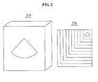
- FIG. 2 is a diagram illustrating an example of a 3D volume data and a variable lookup table according to an exemplary embodiment of the present invention.
- the 3D volume data 210 is 3D-scanned sample data in ultrasound system 100, and the variable lookup table 220 stores a location of each sampling during the 3D scan conversion.
- the lookup table generating unit 120 generates a variable lookup table based on a location of the acquired ultrasound data. That is, the lookup table generating unit 120 receives the acquired ultrasound data from the data acquiring unit 110, and generates the variable lookup table where a location of sampling with respect to the ultrasound data is stored. The variable lookup table focuses on the acquired ultrasound data to have different sizes based on the location. Also, the variable lookup table gradually decreases a size of the acquired ultrasound data based on the size of the acquired ultrasound data of a location where a focus is on, when the focus progresses back and forth.
- variable lookup table sets, to 1, a size of the acquired ultrasound data of a location where the focus is on, the size being variable based on the location, and gradually decreases the size of the acquired ultrasound data of the location where the focuses is on, when the focus progressed back and forth.
- An image of the location where the focus is on is clear, and a back and a forth of the image is out of focus, thereby having a fade-out effect.
- the 3D rendering unit 130 may perform a 3D rendering with reference to the generated lookup table. That is, the 3D rendering unit 130 receives the lookup table from the lookup table generating unit 120, and performs the 3D rendering with respect to the acquired ultrasound data with reference to the lookup table, and transfers a result of the 3D rendering to the display unit 140.
- the display unit 140 displays the result of the 3D rendering. That is, the display unit 140 receives the result of the 3D rendering from the 3D rendering unit 130, and displays the result of the 3D rendering.
- the changing unit 150 changes a location of the acquired ultrasound data based on a request from a user. That is, the changing unit 150 reports, to the lookup table generating unit 120 or the 3D rendering unit 130, whether the location is changed based on the request from the user.
- the lookup table generating unit 120 regenerates the variable lookup table by changing the size based on the changed location. That is, the lookup table generating unit 120 determines whether the location is changed from the changing unit 150, and regenerates the variable lookup table based on a changed location, when the location is changed.
- the 3D rendering unit 130 performs 3D rendering with reference to the regenerated variable lookup table. Also, when the location is not changed, the 3D rendering unit 130 performs rendering with reference to the existing variable lookup table.
- the ultrasound system 100 enables an image of a location where a focus is on to be clear, and enables a back and forth of the image to be out of focus, thereby having a fade out effect.
- the ultrasound system 100 naturally acquires an interpolation effect during the sampling, and thus, a wood grain artifact is eliminated and a lookup table is minimally used.
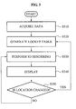
- FIG. 3 is a flowchart illustrating a method of managing a variable lookup table according to an exemplary embodiment of the present invention.
- the ultrasound system 100 acquires ultrasound data in operation S310. That is, the ultrasound system 100 acquires the ultrasound data via the data acquiring unit 110 in operation S310.
- the ultrasound system 100 generates a variable lookup table based on a location of the acquired ultrasound data. That is, in operation S320, the ultrasound system 100 generates, through the lookup table generating unit 120, the variable lookup table that enables the acquired ultrasound data to have different size based on the location of the acquired ultrasound data. As an example, in operation 320, the ultrasound system 100 may generate, through the lookup table generating unit 120, the variable lookup table where a location of sampling with respect to the ultrasound data is stored. The variable lookup table may focus on the ultrasound data to be in different sizes based on the location. Also, the variable lookup table may gradually decreases a size of the ultrasound data based on the size of the ultrasound data of a location where a focus is on, when the focus progresses back and forth.
- the ultrasound system 100 enables, through the lookup table generating unit, the lookup table to set, to 1, the size of the acquired ultrasound data of the location where the focus is on, the size being variable based on the location, and gradually decreases the size of the acquired ultrasound data of the location where the focuses is on, when the focus progressed back and forth.
- An image of the location where the focus is on is clear, and a back and a forth of the image is out of focus, thereby having a fade out effect.
- the ultrasound system 100 performs 3D rendering with reference to the variable lookup table. That is, in operation S330, the ultrasound system 100 performs, through the 3D rendering unit 130, the 3D rendering with respect to the acquired ultrasound data with reference to the generated lookup table.
- the ultrasound system 100 displays a result of the 3D rendering. That is, in operation S340, the ultrasound system 100 displays, through the display unit 140, the result of the 3D rendering.
- the ultrasound system 100 determines whether to change a location based on a request from a user. That is, in operation S350, the ultrasound system 100 determines, through the changing unit 150, whether to change the location based on the request from the user.
- the ultrasound system 100 proceeds again with operation S320 to regenerate the variable lookup table based on the changed location. Also, the ultrasound system 100 performs the 3D rendering based on the variable lookup table regenerated based on the changed location.
- the ultrasound system 100 proceeds again with operation S330 and performs the 3D rendering with reference to the existing variable lookup table.
- variable lookup table managing method in the ultrasound system enables an image of a location where a focus is on to be clear, and a back and a forth of the image is out of focus, thereby having a fade-out effect.
- variable lookup table managing method in the ultrasound system naturally acquires an interpolation effect during sampling, and thus, a wood grain artifact is eliminated and a lookup table is minimally used.
- variable lookup table managing method may be recorded in computer-readable media including program instructions to implement various operations embodied by a computer.
- the media may also include, alone or in combination with the program instructions, data files, data structures, and the like.
- Examples of computer-readable media include magnetic media such as hard disks, floppy disks, and magnetic tape; optical media such as CD ROM disks and DVDs; magneto-optical media such as optical disks; and hardware devices that are specially configured to store and perform program instructions, such as read-only memory (ROM), random access memory (RAM), flash memory, and the like.
- Examples of program instructions include both machine code, such as produced by a compiler, and files containing higher level code that may be executed by the computer using an interpreter.
- the described hardware devices may be configured to act as one or more software modules in order to perform the operations of the above-described example embodiments, or vice versa.
Landscapes
- Engineering & Computer Science (AREA)
- Physics & Mathematics (AREA)
- Life Sciences & Earth Sciences (AREA)
- Health & Medical Sciences (AREA)
- Remote Sensing (AREA)
- Radar, Positioning & Navigation (AREA)
- General Physics & Mathematics (AREA)
- Biophysics (AREA)
- Surgery (AREA)
- Veterinary Medicine (AREA)
- Public Health (AREA)
- General Health & Medical Sciences (AREA)
- Animal Behavior & Ethology (AREA)
- Nuclear Medicine, Radiotherapy & Molecular Imaging (AREA)
- Pathology (AREA)
- Radiology & Medical Imaging (AREA)
- Biomedical Technology (AREA)
- Heart & Thoracic Surgery (AREA)
- Medical Informatics (AREA)
- Molecular Biology (AREA)
- Acoustics & Sound (AREA)
- Computer Graphics (AREA)
- Computer Networks & Wireless Communication (AREA)
- Theoretical Computer Science (AREA)
- General Engineering & Computer Science (AREA)
- Ultra Sonic Daignosis Equipment (AREA)
Abstract
Description
- The present invention relates to an ultrasound system having a variable lookup table and a variable lookup table managing method, and more particularly, to a variable lookup table managing method and an ultrasound system having a variable lookup table that stores each sampling location during a three-dimensional (3D) scan conversion, focuses on ultrasound data to be in different sizes based on the location, and gradually decreases a size of the ultrasound data of a location where a focus is on based on the size of the ultrasound data of the location where the focus is on when the focus progresses back and forth.
- Generally, an ultrasound system transmits an ultrasound signal to a predetermined internal part of a body from a surface of a target object, and acquires an image related to a section of a soft tissue or a blood vessel by using information of an ultrasound signal that is reflected from a tissue inside of the body.
- The ultrasound system is small and inexpensive, and has a high stability since it has no coated wire, and thus, the ultrasound system is widely used together with an X-ray diagnostic device, a computerized tomography (CT) scanner, a magnetic resonance image (MRI) device, a nuclear medicine diagnostic device, and the like. In particular, the ultrasound system may display the internal part of the body in real-time, and thus, may have various types of usage.
- As an area where the ultrasound system is utilized expands, various demands with respect to an ultrasound image provided by the ultrasound system continuously exist. In particular, the ultrasound system needs to obtain a three-dimensional (3D) ultrasound image, since a close observation of a lesion or a tissue of a patient is required to perform a medical examination, a biopsy, an operation, and the like.
- The ultrasound system requires a 3D scan conversion to use a 3D volume rendering technology. However, the conventional ultrasound system computes a value through a trigonometrical function value, thereby having a problem of expending a great deal of time. Also, the conventional ultrasound system has a problem that a wood grain artifact, which is a sampling artifact, is generated during the 3D rendering operation. Also, to provide perspective, various attempts have been made for the 3D volume rendering in the ultrasound system.
- An aspect of the present invention provides an ultrasound system that has a three-dimensional (3D) lookup table that stores a location of each sampling during a 3D scan conversion and a variable lookup table managing method.
- Another aspect of the present invention provides a variable lookup table managing method and an ultrasound system including a lookup table that sets, to 1, a size of ultrasound data of a location where a focus is on and gradually decreases the size of the ultrasound data of the location where the focus is on when the focus progresses back and forth.
- According to example embodiments, there may be provided an ultrasound system, including a data acquiring unit to acquire ultrasound data, a lookup table generating unit to generate a variable lookup table according to a location of the acquired ultrasound data, a 3D rendering unit to perform 3D rendering with reference to the generated variable lookup table, and a display unit to display a result of the 3D rendering.
- Also, the lookup table generating unit generates the variable lookup table that stores a location where a sampling is performed with respect to the acquired ultrasound data.
- Also, the variable lookup table focuses on the acquired ultrasound data to have different sizes based on the location.
- Also, the variable lookup table gradually decreases a size of the acquired ultrasound data based on the size of the acquired ultrasound data of a location where a focus is on, when the focus progresses back and forth.
- Also, the ultrasound system further comprises a changing unit to change a location according to a request from a user, and the lookup table generating unit regenerates the variable lookup table based on the changed location.
- According to example embodiments, there may be provided a method of managing a variable lookup table in an ultrasound system comprising a data acquiring unit, a lookup table generating unit, a 3D rendering unit, and a display unit, the method including acquiring, by the data acquiring unit, ultrasound data, generating, by the lookup table generating unit, the variable lookup table according to a location of the acquired ultrasound data, performing, by the 3D rendering unit, 3D rendering with reference to the generated variable lookup table, and displaying, by the display unit, a result of the 3D rendering.
- Additional aspects and/or advantages will be set forth in part in the description which follows and, in part, will be apparent from the description, or may be learned by practice of the embodiments.
- According to the present invention, there may be provided an ultrasound system that enables an image of a location where a focus is on to be clear, and a back and a forth of the image is out of focus, thereby having a fade-out effect.
- Also, the present invention naturally acquires an interpolation effect during sampling, and thus, a wood grain artifact is eliminated, and a lookup table is minimally used.
- These and/or other aspects and advantages will become apparent and more readily appreciated from the following description of the embodiments, taken in conjunction with the accompanying drawings of which:
- FIG. 1
- is a diagram illustrating a configuration of an ultrasound system having a variable lookup table according to an exemplary embodiment of the present invention;
- FIG. 2
- is a diagram illustrating an example of a three-dimensional (3D) volume data and a variable lookup table according to an exemplary embodiment of the present invention; and
- FIG. 3
- is a flowchart illustrating a method of managing a variable lookup table according to an exemplary embodiment of the present invention.
- Reference will now be made in detail to example embodiments, examples of which are illustrated in the accompanying drawings, wherein like reference numerals refer to the like elements throughout. An ultrasound diagnosis apparatus utilizing a touch interaction is described below to explain the present disclosure by referring to the figures.
-
FIG. 1 is a diagram illustrating a configuration of an ultrasound system having a variable lookup table according to an exemplary embodiment of the present invention. - Referring to
FIG. 1 , theultrasound system 100 according to an exemplary embodiment of the present invention includes adata acquiring unit 110, a lookuptable generating unit 120, a3D rendering unit 130, adisplay unit 140, and a changingunit 150. - The
ultrasound system 100 may have a three-dimensional (3D) lookup table which stores a location of each sampling during a 3D scan conversion. - The
data acquiring unit 110 may obtain ultrasound data with respect to a sample from theultrasound system 100. That is, thedata acquiring unit 110 acquires the ultrasound data with respect to the sample used for 3D scan conversion from theultrasound system 100, and transfers the acquired ultrasound data to the lookuptable generating unit 120. -
FIG. 2 is a diagram illustrating an example of a 3D volume data and a variable lookup table according to an exemplary embodiment of the present invention. - Referring to
FIG. 2 , the3D volume data 210 is 3D-scanned sample data inultrasound system 100, and the variable lookup table 220 stores a location of each sampling during the 3D scan conversion. - The lookup
table generating unit 120 generates a variable lookup table based on a location of the acquired ultrasound data. That is, the lookuptable generating unit 120 receives the acquired ultrasound data from thedata acquiring unit 110, and generates the variable lookup table where a location of sampling with respect to the ultrasound data is stored. The variable lookup table focuses on the acquired ultrasound data to have different sizes based on the location. Also, the variable lookup table gradually decreases a size of the acquired ultrasound data based on the size of the acquired ultrasound data of a location where a focus is on, when the focus progresses back and forth. - As an example, the variable lookup table sets, to 1, a size of the acquired ultrasound data of a location where the focus is on, the size being variable based on the location, and gradually decreases the size of the acquired ultrasound data of the location where the focuses is on, when the focus progressed back and forth. An image of the location where the focus is on is clear, and a back and a forth of the image is out of focus, thereby having a fade-out effect.
- The
3D rendering unit 130 may perform a 3D rendering with reference to the generated lookup table. That is, the3D rendering unit 130 receives the lookup table from the lookuptable generating unit 120, and performs the 3D rendering with respect to the acquired ultrasound data with reference to the lookup table, and transfers a result of the 3D rendering to thedisplay unit 140. - The
display unit 140 displays the result of the 3D rendering. That is, thedisplay unit 140 receives the result of the 3D rendering from the3D rendering unit 130, and displays the result of the 3D rendering. - The changing
unit 150 changes a location of the acquired ultrasound data based on a request from a user. That is, the changingunit 150 reports, to the lookuptable generating unit 120 or the3D rendering unit 130, whether the location is changed based on the request from the user. - The lookup
table generating unit 120 regenerates the variable lookup table by changing the size based on the changed location. That is, the lookuptable generating unit 120 determines whether the location is changed from the changingunit 150, and regenerates the variable lookup table based on a changed location, when the location is changed. - The
3D rendering unit 130 performs 3D rendering with reference to the regenerated variable lookup table. Also, when the location is not changed, the3D rendering unit 130 performs rendering with reference to the existing variable lookup table. - As described in the above description, the
ultrasound system 100 enables an image of a location where a focus is on to be clear, and enables a back and forth of the image to be out of focus, thereby having a fade out effect. - Also, the
ultrasound system 100 naturally acquires an interpolation effect during the sampling, and thus, a wood grain artifact is eliminated and a lookup table is minimally used. -
FIG. 3 is a flowchart illustrating a method of managing a variable lookup table according to an exemplary embodiment of the present invention. - Referring to
FIGS. 1 through 3 , theultrasound system 100 acquires ultrasound data in operation S310. That is, theultrasound system 100 acquires the ultrasound data via thedata acquiring unit 110 in operation S310. - In operation S320, the
ultrasound system 100 generates a variable lookup table based on a location of the acquired ultrasound data. That is, in operation S320, theultrasound system 100 generates, through the lookuptable generating unit 120, the variable lookup table that enables the acquired ultrasound data to have different size based on the location of the acquired ultrasound data. As an example, inoperation 320, theultrasound system 100 may generate, through the lookuptable generating unit 120, the variable lookup table where a location of sampling with respect to the ultrasound data is stored. The variable lookup table may focus on the ultrasound data to be in different sizes based on the location. Also, the variable lookup table may gradually decreases a size of the ultrasound data based on the size of the ultrasound data of a location where a focus is on, when the focus progresses back and forth. - As an example, in operation S320, the
ultrasound system 100 enables, through the lookup table generating unit, the lookup table to set, to 1, the size of the acquired ultrasound data of the location where the focus is on, the size being variable based on the location, and gradually decreases the size of the acquired ultrasound data of the location where the focuses is on, when the focus progressed back and forth. An image of the location where the focus is on is clear, and a back and a forth of the image is out of focus, thereby having a fade out effect. - In operation S330, the
ultrasound system 100 performs 3D rendering with reference to the variable lookup table. That is, in operation S330, theultrasound system 100 performs, through the3D rendering unit 130, the 3D rendering with respect to the acquired ultrasound data with reference to the generated lookup table. - In operation S340, the
ultrasound system 100 displays a result of the 3D rendering. That is, in operation S340, theultrasound system 100 displays, through thedisplay unit 140, the result of the 3D rendering. - In operation S350, the
ultrasound system 100 determines whether to change a location based on a request from a user. That is, in operation S350, theultrasound system 100 determines, through the changingunit 150, whether to change the location based on the request from the user. - When the location is determined to be changed, the
ultrasound system 100 proceeds again with operation S320 to regenerate the variable lookup table based on the changed location. Also, theultrasound system 100 performs the 3D rendering based on the variable lookup table regenerated based on the changed location. - Conversely, when the location is determined to not be changed, the
ultrasound system 100 proceeds again with operation S330 and performs the 3D rendering with reference to the existing variable lookup table. - As described in the above description, a variable lookup table managing method in the ultrasound system enables an image of a location where a focus is on to be clear, and a back and a forth of the image is out of focus, thereby having a fade-out effect.
- Also, the variable lookup table managing method in the ultrasound system naturally acquires an interpolation effect during sampling, and thus, a wood grain artifact is eliminated and a lookup table is minimally used.
- The variable lookup table managing method according to the above-described example embodiments may be recorded in computer-readable media including program instructions to implement various operations embodied by a computer. The media may also include, alone or in combination with the program instructions, data files, data structures, and the like. Examples of computer-readable media include magnetic media such as hard disks, floppy disks, and magnetic tape; optical media such as CD ROM disks and DVDs; magneto-optical media such as optical disks; and hardware devices that are specially configured to store and perform program instructions, such as read-only memory (ROM), random access memory (RAM), flash memory, and the like. Examples of program instructions include both machine code, such as produced by a compiler, and files containing higher level code that may be executed by the computer using an interpreter. The described hardware devices may be configured to act as one or more software modules in order to perform the operations of the above-described example embodiments, or vice versa.
- Although a few example embodiments have been shown and described, it would be appreciated by those skilled in the art that changes may be made in these example embodiments without departing from the principles and spirit of the invention, the scope of which is defined in the claims and their equivalents.
Claims (11)
- An ultrasound system, comprising:a data acquiring unit to acquire ultrasound data;a lookup table generating unit to generate a variable lookup table according to a location of the acquired ultrasound data;a three-dimensional (3D) rendering unit to perform 3D rendering with reference to the generated variable lookup table; anda display unit to display a result of the 3D rendering.
- The ultrasound system of claim 1, wherein the lookup table generating unit generates the variable lookup table that stores a location where a sampling is performed with respect to the acquired ultrasound data.
- The ultrasound system of claim 2, wherein the variable lookup table focuses on the acquired ultrasound data to have different sizes based on the location.
- The ultrasound system of claim 3, wherein the variable lookup table gradually decreases a size of the acquired ultrasound data based on the size of the acquired ultrasound data of a location where a focus is on, when the focus progresses back and forth.
- The ultrasound system of claim 1, wherein:the ultrasound system further comprises a changing unit to change a location according to a request from a user; andthe lookup table generating unit regenerates the variable lookup table based on the changed location.
- A method of managing a variable lookup table in an ultrasound system comprising a data acquiring unit, a lookup table generating unit, a 3D rendering unit, and a display unit, the method comprising:acquiring, by the data acquiring unit, ultrasound data;generating, by the lookup table generating unit, the variable lookup table according to a location of the acquired ultrasound data;performing, by the 3D rendering unit, 3D rendering with reference to the generated variable lookup table; anddisplaying, by the display unit, a result of the 3D rendering.
- The method of claim 6, wherein the generating of the variable lookup table comprises:storing, by the lookup table generating unit, a location of sampling with respect to the acquired ultrasound data in the variable lookup table.
- The method of claim 6, wherein the variable lookup table focuses on the acquired ultrasound data to have different sizes based on the location.
- The method of claim 8, wherein the variable lookup table gradually decreases a size of the acquired ultrasound data of a location where a focus is on based on the size of the acquired ultrasound data of a location where a focus is on, when the focus progresses back and fourth.
- The method of claim 6, wherein:the ultrasound system further comprises a changing unit, andthe method further comprises changing, by the changing unit, a location based on a request from the user, andthe generating of the variable lookup table regenerates the variable lookup table based on the changed location.
- A computer readable recoding medium storing a program implementing the method of claim 6.
Applications Claiming Priority (1)
| Application Number | Priority Date | Filing Date | Title |
|---|---|---|---|
| KR1020090075853A KR101085221B1 (en) | 2009-08-17 | 2009-08-17 | Ultrasound system having variable look up table and method for managing variable look up table |
Publications (2)
| Publication Number | Publication Date |
|---|---|
| EP2290399A2 true EP2290399A2 (en) | 2011-03-02 |
| EP2290399A3 EP2290399A3 (en) | 2013-01-02 |
Family
ID=43301758
Family Applications (1)
| Application Number | Title | Priority Date | Filing Date |
|---|---|---|---|
| EP10152638A Ceased EP2290399A3 (en) | 2009-08-17 | 2010-02-04 | Ultrasound system having variable lookup table and method for managing variable lookup table |
Country Status (3)
| Country | Link |
|---|---|
| US (1) | US9207321B2 (en) |
| EP (1) | EP2290399A3 (en) |
| KR (1) | KR101085221B1 (en) |
Family Cites Families (8)
| Publication number | Priority date | Publication date | Assignee | Title |
|---|---|---|---|---|
| US5315512A (en) * | 1989-09-01 | 1994-05-24 | Montefiore Medical Center | Apparatus and method for generating image representations of a body utilizing an ultrasonic imaging subsystem and a three-dimensional digitizer subsystem |
| US6193661B1 (en) * | 1999-04-07 | 2001-02-27 | Agilent Technologies, Inc. | System and method for providing depth perception using single dimension interpolation |
| US6685645B1 (en) * | 2001-10-20 | 2004-02-03 | Zonare Medical Systems, Inc. | Broad-beam imaging |
| US6530885B1 (en) * | 2000-03-17 | 2003-03-11 | Atl Ultrasound, Inc. | Spatially compounded three dimensional ultrasonic images |
| US20040138560A1 (en) * | 2002-12-02 | 2004-07-15 | Gianluca Paladini | Real-time scan conversion and rendering of ultrasound data |
| KR100697728B1 (en) | 2004-10-22 | 2007-03-21 | 주식회사 메디슨 | Apparatus and method for improving quality of an ultrasound sectional plane image |
| KR100856042B1 (en) * | 2005-10-07 | 2008-09-03 | 주식회사 메디슨 | Ultrasound imaging system for extracting volume of object from ultrasound image and method for the same |
| KR100875414B1 (en) * | 2006-11-22 | 2008-12-23 | 주식회사 메디슨 | Ultrasonic Image Diagnosis Apparatus and Method for Displaying Image Information on a Specific Area |
-
2009
- 2009-08-17 KR KR1020090075853A patent/KR101085221B1/en active IP Right Grant
-
2010
- 2010-02-04 EP EP10152638A patent/EP2290399A3/en not_active Ceased
- 2010-03-19 US US12/727,982 patent/US9207321B2/en active Active
Non-Patent Citations (1)
| Title |
|---|
| None |
Also Published As
| Publication number | Publication date |
|---|---|
| KR20110018187A (en) | 2011-02-23 |
| US20110040182A1 (en) | 2011-02-17 |
| EP2290399A3 (en) | 2013-01-02 |
| KR101085221B1 (en) | 2011-11-21 |
| US9207321B2 (en) | 2015-12-08 |
Similar Documents
| Publication | Publication Date | Title |
|---|---|---|
| US7986822B2 (en) | System and method for X-ray based assessment of aneurysm pulsation | |
| JP4698589B2 (en) | Apparatus and method for displaying ultrasound image of blood vessel | |
| JP6085366B2 (en) | Ultrasound imaging system for image guidance procedure and method of operation thereof | |
| JP4864397B2 (en) | Method and system for continuously reconstructing a multi-resolution 3D image using target area information | |
| EP3870067B1 (en) | Intraluminal ultrasound imaging with automatic and assisted labels and bookmarks | |
| CN102090902B (en) | The control method of medical imaging device, medical image-processing apparatus and Ultrasonographic device | |
| JP4901358B2 (en) | Automatic detection device of attention point in medical image data | |
| KR102268668B1 (en) | The method and apparatus for displaying a plurality of different images of an object | |
| JP2016530043A (en) | System for selecting and displaying images using an intravascular ultrasound imaging system | |
| JP2008136867A (en) | Imaging parameter storage method | |
| JP2012503514A (en) | Generation of a standard protocol for studying 3D ultrasound image data | |
| US20160030008A1 (en) | System and method for registering ultrasound information to an x-ray image | |
| KR20130138612A (en) | The method and apparatus for displaying a two-dimensional image and a three-dimensional image | |
| JP2009268741A (en) | Mri image diagnostic apparatus and mr image forming method | |
| US9872655B2 (en) | PAE treatment for BPH | |
| JP5314342B2 (en) | Method and system for evaluating images | |
| US20120046549A1 (en) | Ultrasound system and method of measuring fetal rib | |
| JP2004283583A (en) | Operation method of image forming medical inspection system | |
| JP5468759B2 (en) | Method and system for collecting a volume of interest based on position information | |
| EP2290399A2 (en) | Ultrasound system having variable lookup table and method for managing variable lookup table | |
| EP2422706A1 (en) | 3D ultrasound system and method for measuring the reflection angles | |
| JP6898047B2 (en) | Quantitative evaluation of time-varying data | |
| Pace et al. | An open-source real-time ultrasound reconstruction system for four-dimensional imaging of moving organs | |
| US20230172571A1 (en) | Providing a result data set | |
| US8077940B2 (en) | Method for reconstructing a three-dimensional target volume in realtime and displaying it |
Legal Events
| Date | Code | Title | Description |
|---|---|---|---|
| PUAI | Public reference made under article 153(3) epc to a published international application that has entered the european phase |
Free format text: ORIGINAL CODE: 0009012 |
|
| AK | Designated contracting states |
Kind code of ref document: A2 Designated state(s): AT BE BG CH CY CZ DE DK EE ES FI FR GB GR HR HU IE IS IT LI LT LU LV MC MK MT NL NO PL PT RO SE SI SK SM TR |
|
| AX | Request for extension of the european patent |
Extension state: AL BA RS |
|
| RAP1 | Party data changed (applicant data changed or rights of an application transferred) |
Owner name: SAMSUNG MEDISON CO., LTD. |
|
| PUAL | Search report despatched |
Free format text: ORIGINAL CODE: 0009013 |
|
| AK | Designated contracting states |
Kind code of ref document: A3 Designated state(s): AT BE BG CH CY CZ DE DK EE ES FI FR GB GR HR HU IE IS IT LI LT LU LV MC MK MT NL NO PL PT RO SE SI SK SM TR |
|
| AX | Request for extension of the european patent |
Extension state: AL BA RS |
|
| RIC1 | Information provided on ipc code assigned before grant |
Ipc: A61B 8/00 20060101ALI20121123BHEP Ipc: G01S 7/52 20060101ALI20121123BHEP Ipc: G01S 15/89 20060101AFI20121123BHEP Ipc: G06T 15/08 20110101ALI20121123BHEP |
|
| 17P | Request for examination filed |
Effective date: 20130701 |
|
| RBV | Designated contracting states (corrected) |
Designated state(s): AT BE BG CH CY CZ DE DK EE ES FI FR GB GR HR HU IE IS IT LI LT LU LV MC MK MT NL NO PL PT RO SE SI SK SM TR |
|
| 17Q | First examination report despatched |
Effective date: 20151012 |
|
| STAA | Information on the status of an ep patent application or granted ep patent |
Free format text: STATUS: THE APPLICATION HAS BEEN REFUSED |
|
| 18R | Application refused |
Effective date: 20170504 |