EP2290239A1 - Shoe - Google Patents
Shoe Download PDFInfo
- Publication number
- EP2290239A1 EP2290239A1 EP09843177A EP09843177A EP2290239A1 EP 2290239 A1 EP2290239 A1 EP 2290239A1 EP 09843177 A EP09843177 A EP 09843177A EP 09843177 A EP09843177 A EP 09843177A EP 2290239 A1 EP2290239 A1 EP 2290239A1
- Authority
- EP
- European Patent Office
- Prior art keywords
- shoe
- end surface
- cylindrical portion
- grooves
- outer peripheral
- Prior art date
- Legal status (The legal status is an assumption and is not a legal conclusion. Google has not performed a legal analysis and makes no representation as to the accuracy of the status listed.)
- Granted
Links
Images




Classifications
-
- F—MECHANICAL ENGINEERING; LIGHTING; HEATING; WEAPONS; BLASTING
- F04—POSITIVE - DISPLACEMENT MACHINES FOR LIQUIDS; PUMPS FOR LIQUIDS OR ELASTIC FLUIDS
- F04B—POSITIVE-DISPLACEMENT MACHINES FOR LIQUIDS; PUMPS
- F04B27/00—Multi-cylinder pumps specially adapted for elastic fluids and characterised by number or arrangement of cylinders
- F04B27/08—Multi-cylinder pumps specially adapted for elastic fluids and characterised by number or arrangement of cylinders having cylinders coaxial with, or parallel or inclined to, main shaft axis
- F04B27/0873—Component parts, e.g. sealings; Manufacturing or assembly thereof
- F04B27/0878—Pistons
- F04B27/0886—Piston shoes
-
- F—MECHANICAL ENGINEERING; LIGHTING; HEATING; WEAPONS; BLASTING
- F04—POSITIVE - DISPLACEMENT MACHINES FOR LIQUIDS; PUMPS FOR LIQUIDS OR ELASTIC FLUIDS
- F04B—POSITIVE-DISPLACEMENT MACHINES FOR LIQUIDS; PUMPS
- F04B27/00—Multi-cylinder pumps specially adapted for elastic fluids and characterised by number or arrangement of cylinders
- F04B27/08—Multi-cylinder pumps specially adapted for elastic fluids and characterised by number or arrangement of cylinders having cylinders coaxial with, or parallel or inclined to, main shaft axis
- F04B27/10—Multi-cylinder pumps specially adapted for elastic fluids and characterised by number or arrangement of cylinders having cylinders coaxial with, or parallel or inclined to, main shaft axis having stationary cylinders
- F04B27/1036—Component parts, details, e.g. sealings, lubrication
- F04B27/109—Lubrication
-
- F—MECHANICAL ENGINEERING; LIGHTING; HEATING; WEAPONS; BLASTING
- F04—POSITIVE - DISPLACEMENT MACHINES FOR LIQUIDS; PUMPS FOR LIQUIDS OR ELASTIC FLUIDS
- F04B—POSITIVE-DISPLACEMENT MACHINES FOR LIQUIDS; PUMPS
- F04B39/00—Component parts, details, or accessories, of pumps or pumping systems specially adapted for elastic fluids, not otherwise provided for in, or of interest apart from, groups F04B25/00 - F04B37/00
- F04B39/02—Lubrication
- F04B39/0223—Lubrication characterised by the compressor type
- F04B39/023—Hermetic compressors
-
- F—MECHANICAL ENGINEERING; LIGHTING; HEATING; WEAPONS; BLASTING
- F04—POSITIVE - DISPLACEMENT MACHINES FOR LIQUIDS; PUMPS FOR LIQUIDS OR ELASTIC FLUIDS
- F04B—POSITIVE-DISPLACEMENT MACHINES FOR LIQUIDS; PUMPS
- F04B39/00—Component parts, details, or accessories, of pumps or pumping systems specially adapted for elastic fluids, not otherwise provided for in, or of interest apart from, groups F04B25/00 - F04B37/00
- F04B39/02—Lubrication
- F04B39/0223—Lubrication characterised by the compressor type
- F04B39/0276—Lubrication characterised by the compressor type the pump being of the reciprocating piston type, e.g. oscillating, free-piston compressors
Definitions
- the present invention relates to a shoe, and more particularly, to an improvement in a shoe used for a swash plate compressor.
- Hemispherical shoes used for swash plate compressors have been conventionally known.
- the hemispherical shoe includes a spherical portion in sliding contact with a hemispherical concave portion on a piston side, and an end surface portion in sliding contact with a swash plate (for example, Patent Literatures 1 to 4).
- Patent Literatures 1 to 4 Recently, there has been a need for swash plate compressors for automobiles to be reduced in cost, be compatible with a new refrigerant, or the like.
- the swash plate compressors are particularly required to be more efficient. To this end, the following improvements in the shoe have been proposed respectively in Patent Literatures 1 to 4.
- Patent Literature 1 the surface roughness of a sliding portion and the surface roughness of a non-sliding portion in the spherical portion of the hemispherical shoe are made different from each other.
- Patent Literature 2 proposes that the spherical portion has a stepped tapered surface.
- Patent Literature 3 proposes that the outer peripheral edge of the hemispherical shoe is largely removed over the entire circumference to thereby form a cylindrical portion.
- Patent Literature 4 proposes that an oil groove having a spiral shape or the like is formed in the spherical portion of the hemispherical shoe.
- a lubricant oil is mixed in a refrigerant in a circulation circuit and is thereby also circulated, so that the lubricant oil is fed to the sliding portion between the shoe and each of the piston and the swash plate.
- the amount of lubricant oil enclosed within the refrigerant circulation circuit has been reduced in recent years.
- the sliding portion between the shoe and each of the piston and the swash plate suffers poor lubricant conditions.
- the lubricant oil is not mixed in the refrigerant in the circulation circuit.
- the present invention provides a shoe including a spherical portion in sliding contact with a hemispherical concave portion of a first movable member, an end surface portion in sliding contact with a flat surface of a second movable member, and a cylindrical portion formed between the spherical portion and the end surface portion, wherein a groove and/or a concave portion is provided in an outer peripheral surface of the cylindrical portion, and a lubricant oil is held in the groove and/or the concave portion.
- Figure 1 shows the internal structure of a swash plate compressor 1.
- the swash plate compressor 1 includes a rotating shaft 2 pivotally supported on an unillustrated housing in a rotatable manner, a swash plate 3 mounted on the rotating shaft 2, a plurality of pistons 4 reciprocating within an unillustrated cylinder bore of the housing, and a plurality of shoes 5 disposed so as to face each other inside each of the pistons 4 and holding the swash plate 3.
- the swash plate 3 is obliquely fixed to the rotating shaft 2, or the inclination angle of the swash plate 3 can be changed.
- the swash plate 3 is held by the two shoes 5 in each of the pistons 4.
- a predetermined coating such as a thermally sprayed layer, a plated layer, and a resin coating is applied on the flat surfaces of the swash plate 3 in sliding contact with the shoes 5.
- the configuration of the swash plate 3 applicable to the present invention is not limited to that described above, and various conventionally known swash plates can be used.
- Sliding surfaces 4a having hemispherical concave portions are formed so as to face each other in the piston 4.
- the shoes 5 convert the rotation of the swash plate 3 into the reciprocating motion of the piston 4 while swinging and sliding on the sliding surfaces 4a.
- the configuration of the swash plate compressor 1 as described above has been conventionally well known, and a further detailed description is omitted.
- the shoe 5 according to a present embodiment includes a spherical portion 5A in sliding contact with the sliding surface 4a of the piston 4, an end surface portion 5B in sliding contact with the flat surface of the swash plate 3, and a circular cylindrical portion 5C formed between the spherical portion 5A and the end surface portion 5B as shown in Figure 2 .
- the shoe 5 according to the present embodiment may be produced from a sintered material, a resin material or the like in addition to iron, copper, and aluminum materials.
- a releasing portion 5D having a flat surface so as not to contact the sliding surface 4a on the piston 4 side is formed on the top of the spherical portion 5A.
- a lubricant oil is thereby allowed to flow into a space formed between the sliding surface 4a and the releasing portion 5D.
- the end surface portion 5B defines a sliding surface in sliding contact with the swash plate 3, and has a crowned shape that slightly bulges about several ⁇ m at its center portion toward the swash plate 3 from the outer peripheral portion.
- the lubricant oil is thereby easily drawn into a space between the end surface portion 5B and the swash plate 3.
- a chamfered portion 5E is formed on the outer peripheral edge of the end surface portion 5B.
- the cylindrical portion 5C of the shoe 5 has a circular cylindrical shape with a constant outer diameter over the entire axial length.
- the axial length of the cylindrical portion 5C is set to be about twice as large as the axial length of the spherical portion 5A.
- the outer peripheral surface of the circular cylindrical portion 5C is not in sliding contact with the swash plate 3 and the sliding surface 4a of the piston 4.
- a plurality of linear oil grooves 5F are formed in the outer peripheral surface of the cylindrical portion 5.
- the oil grooves 5F are circumferentially formed in the outer peripheral surface of the cylindrical portion 5C at equal pitches so as to be inclined 45 degrees to an axis C of the shoe 5.
- each of the oil grooves 5F reaches the spherical portion 5A, and the other end of each of the oil grooves 5F reaches the chamfered portion 5E, that is, the outer peripheral edge of the end surface portion 5B.
- the sectional shape of the oil groove 5F is a horizontally long rectangle which has a constant depth and has a larger width than the depth as shown in Figure 3 .
- the width of the oil groove 5F is preferably 0.01 to 2 mm, and the depth of the oil groove 5F is preferably 0.001 to 1 mm.
- the plurality of oil grooves 5F are formed in the outer peripheral surface of the cylindrical portion 5C from the end surface portion 5B to the spherical portion 5A in the shoe 5 according to the present embodiment.
- the oil grooves 5F are formed in the outer peripheral surface of the cylindrical portion 5C by knurling, turning, etching or the like.
- the retention of the lubricant oil is improved in comparison with the conventional shoe described above, so that better lubricity is obtained.
- the operation will be described in detail.
- a refrigerant including the lubricant oil axially flows around the outer peripheral surface of the cylindrical portion 5C, the lubricant oil included in the refrigerant enters each of the oil grooves 5F of the cylindrical portion 5C, and is captured therein to be easily separated from the refrigerant as shown in Figure 4 . Therefore, when the swash plate compressor 1 is not started, that is, when the refrigerant is not circulated in a circulation circuit, the lubricant oil separated from the refrigerant is held in each of the oil grooves 5F.
- the lubricant oil is not mixed in the refrigerant.
- the lubricant oil is held in each of the oil grooves 5F of the shoe 5 in advance, the lubricant oil is fed from each of the oil grooves 5F to the spherical portion 5A and the end surface portion 5B, which are sliding portions, when the shoe 5 slides.
- the lubricant oil held in the plurality of oil grooves 5F is fed to the spherical portion 5A and the end surface portion 5B, which are the sliding portions, when the swash plate compressor 1 is started, so that the shoe 5 having good lubricity can be provided.
- the cylindrical portion 5C is formed in the shoe 5 of the present embodiment, the shoe 5 itself is reduced in weight in comparison with the conventional hemispherical shoe. Therefore, by using the shoe 5 of the present embodiment, the swash plate compressor 1 capable of suppressing the occurrence of seizure and abnormal sound in the sliding portion between the shoe 5 and each of the swash plate 3 and the sliding surface 4a, and having high durability and efficiency can be provided.
- Figures 5 to 9 show other embodiments to which the present invention is applied.
- the orientation and shape of the oil grooves 5F are changed. That is, in the shoe 5 shown in Figure 5 , oil grooves 5F are formed inclined 45 degrees to the axis C such that the inclination direction thereof is opposite to that of the aforementioned first embodiment.
- V-shaped oil grooves 5F are circumferentially formed at equal pitches in the outer peripheral surface of the cylindrical portion 5C.
- One end of each of the V-shaped oil grooves 5F reaches the spherical portion 5A, and the other end of each of the oil grooves 5F reaches the chamfered portion 5E (the outer peripheral edge of the end surface portion 5B).
- linear oil grooves 5F are formed parallel to the axial direction at equal pitches in the outer peripheral surface of the cylindrical portion 5C.
- One end of each of the oil grooves 5F reaches the spherical portion 5A, and the other end reaches the chamfered portion 5E (the outer peripheral edge of the end surface portion 5B).
- a spiral oil groove 5F is formed in the outer peripheral surface of the cylindrical portion 5C.
- One end of the oil groove 5F reaches the spherical portion 5A, and the other end reaches the chamfered portion 5E (the outer peripheral edge of the end surface portion 5B).
- the shoe 5 in each of the embodiments shown in Figures 5 to 8 described above is configured such that the spherical portion 5A and the end surface portion 5B, which are the sliding portions, are in communication with each other through the oil groove 5F. That is, when the shoe 5 is moved, the lubricant oil held in the oil groove 5F is fed to the spherical portion 5A and the end surface portion 5B as in the first embodiment shown in Figure 2 .
- the other end of the oil groove 5F may not reach the end surface portion 5B. That is, in this case, only the one end of the oil groove 5F reaches the spherical portion 5A.
- ring-shaped oil grooves 5F are formed perpendicular to the axis C at equal pitches in the outer peripheral surface of the cylindrical portion 5C.
- the sectional shape of the oil groove 5F is the same rectangular sectional shape as that of the aforementioned first embodiment. The same operation and effect as those of the first embodiment in Figure 2 can be also obtained in each of the embodiments shown in Figures 5 to 9 .
- the sectional shape and arrangement density of the oil grooves 5F in each of the aforementioned embodiments may be changed as shown in Figures 10 . That is, in Figure 10(a) , the sectional shape of the oil groove 5F is a triangular shape, and in Figure 10(b) , the sectional shape of the oil groove 5F is an arc shape. Furthermore, Figures 10(c) to 10(e) show embodiments in which the adjacent oil grooves 5F are arranged as close as possible to each other.
- Figures 11 and 12 show yet other embodiments according to the present invention.
- a plurality of concave portions 5G are formed in the outer peripheral surface of the cylindrical portion 5C instead of the oil grooves 5F.
- circular concave portions 5G having the same dimensions as each other are formed in a staggered manner in the outer peripheral surface of the cylindrical portion 5C.
- square concave portions 5G having the same dimensions as each other are formed in the outer peripheral surface of the cylindrical portion 5C.
- a plurality of triangular or oval concave portions may be also formed in the outer peripheral surface of the cylindrical portion 5C instead of the circular and square concave portions 5G.
- the shoe 5 where the plurality of concave portions 5G are formed in the outer peripheral surface of the cylindrical portion 5C can also produce the same operation and effect as those of the aforementioned first embodiment.
- Figures 13 to 15 show yet other embodiments according to the present invention.
- the shape of the cylindrical portion 5C is changed.
- the cylindrical portion 5C of the shoe 5 is formed in a tapered shape which is gradually reduced in diameter from the end surface portion 5B toward the spherical portion 5A.
- the plurality of oil grooves 5F similar to those of the first embodiment in Figure 2 are formed in the outer peripheral surface of the cylindrical portion 5C having such a tapered shape.
- the cylindrical portion 5C of the shoe 5 is formed in a tapered shape which is gradually reduced in diameter from the spherical portion 5A toward the end surface portion 5B.
- the linear oil grooves 5F are formed in the outer peripheral surface of the cylindrical portion 5C having such a tapered shape.
- the cylindrical portion 5C has a drum shape whose axial center portion expands outward in the radial direction so as to have a largest outer diameter, and the plurality of linear oil grooves 5F are formed in the outer peripheral surface.
- the shoe 5 in each of the embodiments shown in Figures 13 to 15 can also produce the same operation and effect as those of the aforementioned first embodiment.
- the plurality of concave portions 5G shown in Figures 11 and 12 may be also formed in the outer peripheral surface of the cylindrical portion 5C instead of the oil grooves 5F.
- the other end of the oil groove 5F may not reach the end surface portion 5B. That is, in this case, only the one end of the oil groove 5F reaches the spherical portion 5A.
- Figure 16 further shows yet another embodiment according to the present invention.
- a flange portion 5H is formed projecting on the outer peripheral edge of the end surface portion 5B of the first embodiment shown in Figure 2 .
- the linear oil grooves 5F are formed in the outer peripheral surface of the cylindrical portion 5C of the shoe 5 in a similar manner to the aforementioned first embodiment.
- the other components in the configuration are the same as those of the first embodiment.
- the shoe 5 shown in Figure 16 can also produce the same operation and effect as those of the aforementioned respective embodiments.
- the flange portion 5H may be also provided projecting on the outer peripheral edge of the end surface portion 5B in the shoe 5 according to the embodiment shown in each of Figures 2 to 9 and 11 to 15 in a similar manner to Figure 16 .
- grid-like oil grooves may be also provided in the outer peripheral surface of the cylindrical portion 5C instead of the linear oil grooves 5F in each of the aforementioned embodiments.
- both the oil grooves 5F and the concave portions 5G may be provided in the outer peripheral surface of the cylindrical portion 5C.
Landscapes
- Engineering & Computer Science (AREA)
- Mechanical Engineering (AREA)
- General Engineering & Computer Science (AREA)
- Manufacturing & Machinery (AREA)
- Compressors, Vaccum Pumps And Other Relevant Systems (AREA)
Abstract
Description
- The present invention relates to a shoe, and more particularly, to an improvement in a shoe used for a swash plate compressor.
- Hemispherical shoes used for swash plate compressors have been conventionally known. The hemispherical shoe includes a spherical portion in sliding contact with a hemispherical concave portion on a piston side, and an end surface portion in sliding contact with a swash plate (for example,
Patent Literatures 1 to 4).
Recently, there has been a need for swash plate compressors for automobiles to be reduced in cost, be compatible with a new refrigerant, or the like. The swash plate compressors are particularly required to be more efficient.
To this end, the following improvements in the shoe have been proposed respectively inPatent Literatures 1 to 4. That is, inPatent Literature 1, the surface roughness of a sliding portion and the surface roughness of a non-sliding portion in the spherical portion of the hemispherical shoe are made different from each other.Patent Literature 2 proposes that the spherical portion has a stepped tapered surface. Also,Patent Literature 3 proposes that the outer peripheral edge of the hemispherical shoe is largely removed over the entire circumference to thereby form a cylindrical portion. Furthermore, Patent Literature 4 proposes that an oil groove having a spiral shape or the like is formed in the spherical portion of the hemispherical shoe. -
- Patent Literature 1: Japanese Patent Laid-Open No.
2001-153039 - Patent Literature 2: Japanese Patent Laid-Open No.
09-280166 - Patent Literature 3: Japanese Patent Laid-Open No.
10-220347 - Patent Literature 4: Japanese Patent Laid-Open No.
11-050959 - In the swash plate compressor, a lubricant oil is mixed in a refrigerant in a circulation circuit and is thereby also circulated, so that the lubricant oil is fed to the sliding portion between the shoe and each of the piston and the swash plate. However, the amount of lubricant oil enclosed within the refrigerant circulation circuit has been reduced in recent years. Thus, the sliding portion between the shoe and each of the piston and the swash plate suffers poor lubricant conditions.
Especially when the swash plate compressor is started, the lubricant oil is not mixed in the refrigerant in the circulation circuit. Thus, even when the refrigerant is circulated in the circulation circuit, the lubricant oil cannot be sufficiently fed to the sliding portion between the shoe and each of the piston and the swash plate through the refrigerant. Seizure thereby easily occurs in the sliding portion between the shoe and each of the piston and the swash plate in a conventional case when the swash plate compressor is started, so that such a problem is caused that abnormal sound and noise are generated due to the abnormal wear of the sliding portion. - In view of the aforementioned circumstances, the present invention provides a shoe including a spherical portion in sliding contact with a hemispherical concave portion of a first movable member, an end surface portion in sliding contact with a flat surface of a second movable member, and a cylindrical portion formed between the spherical portion and the end surface portion,
wherein a groove and/or a concave portion is provided in an outer peripheral surface of the cylindrical portion, and a lubricant oil is held in the groove and/or the concave portion. - With the above configuration, in a case where the shoe is used for a swash plate compressor, a lubricant oil separated from a refrigerant is held in the oil groove or the concave portion of the shoe when the swash plate compressor is not started. Therefore, even when the lubricant oil is not mixed in the refrigerant at the time of starting the swash plate compressor, the lubricant oil held in the oil groove or the concave portion is fed to the spherical portion and the end surface portion of the shoe, which are the sliding portions. Accordingly, the shoe having good lubricity even when the swash plate compressor is started can be provided.
-
- [
Figure 1] Figure 1 is a sectional view illustrating a main portion in a swash plate compressor according to an embodiment of the present invention. - [
Figure 2] Figure 2 is an elevation view of a shoe shown inFigure 1 . - [
Figure 3] Figure 3 is a sectional view of a portion indicated by an arrow III inFigure 2 taken along an axial direction. - [
Figure 4] Figure 4 is a schematic view illustrating the flow of a refrigerant with respect to anoil groove 5F shown inFigure 3 and the state of a lubricant oil captured in theoil groove 5F. - [
Figure 5] Figure 5 is an elevation view of a shoe illustrating another embodiment of the present invention. - [
Figure 6] Figure 6 is an elevation view of a shoe illustrating another embodiment of the present invention. - [
Figure 7] Figure 7 is an elevation view of a shoe illustrating another embodiment of the present invention. - [
Figure 8] Figure 8 is an elevation view of a shoe illustrating another embodiment of the present invention. - [
Figure 9] Figure 9 is an elevation view of a shoe illustrating another embodiment of the present invention. - [
Figure 10] Figures 10 are sectional views illustrating other embodiments regarding the oil groove shown inFigures 2 and5 to 9 . - [
Figure 11] Figure 11 is an elevation view of a shoe illustrating another embodiment of the present invention. - [
Figure 12] Figure 12 is an elevation view of a shoe illustrating another embodiment of the present invention. - [
Figure 13] Figure 13 is an elevation view of a shoe illustrating another embodiment of the present invention. - [
Figure 14] Figure 14 is an elevation view of a shoe illustrating another embodiment of the present invention. - [
Figure 15] Figure 15 is an elevation view of a shoe illustrating another embodiment of the present invention. - [
Figure 16] Figure 16 is an elevation view of a shoe illustrating another embodiment of the present invention. - In the following, the present invention will be described based on embodiments shown in the drawings.
Figure 1 shows the internal structure of aswash plate compressor 1. Theswash plate compressor 1 includes a rotatingshaft 2 pivotally supported on an unillustrated housing in a rotatable manner, aswash plate 3 mounted on the rotatingshaft 2, a plurality of pistons 4 reciprocating within an unillustrated cylinder bore of the housing, and a plurality ofshoes 5 disposed so as to face each other inside each of the pistons 4 and holding theswash plate 3.
Theswash plate 3 is obliquely fixed to the rotatingshaft 2, or the inclination angle of theswash plate 3 can be changed. Theswash plate 3 is held by the twoshoes 5 in each of the pistons 4. A predetermined coating such as a thermally sprayed layer, a plated layer, and a resin coating is applied on the flat surfaces of theswash plate 3 in sliding contact with theshoes 5. Note that the configuration of theswash plate 3 applicable to the present invention is not limited to that described above, and various conventionally known swash plates can be used.
Slidingsurfaces 4a having hemispherical concave portions are formed so as to face each other in the piston 4. Theshoes 5 convert the rotation of theswash plate 3 into the reciprocating motion of the piston 4 while swinging and sliding on thesliding surfaces 4a.
The configuration of theswash plate compressor 1 as described above has been conventionally well known, and a further detailed description is omitted. - The
shoe 5 according to a present embodiment includes aspherical portion 5A in sliding contact with thesliding surface 4a of the piston 4, anend surface portion 5B in sliding contact with the flat surface of theswash plate 3, and a circularcylindrical portion 5C formed between thespherical portion 5A and theend surface portion 5B as shown inFigure 2 . Theshoe 5 according to the present embodiment may be produced from a sintered material, a resin material or the like in addition to iron, copper, and aluminum materials.
A releasingportion 5D having a flat surface so as not to contact thesliding surface 4a on the piston 4 side is formed on the top of thespherical portion 5A. A lubricant oil is thereby allowed to flow into a space formed between the slidingsurface 4a and the releasingportion 5D.
Theend surface portion 5B defines a sliding surface in sliding contact with theswash plate 3, and has a crowned shape that slightly bulges about several µm at its center portion toward theswash plate 3 from the outer peripheral portion. The lubricant oil is thereby easily drawn into a space between theend surface portion 5B and theswash plate 3. A chamferedportion 5E is formed on the outer peripheral edge of theend surface portion 5B. - Next, the
cylindrical portion 5C of theshoe 5 has a circular cylindrical shape with a constant outer diameter over the entire axial length. The axial length of thecylindrical portion 5C is set to be about twice as large as the axial length of thespherical portion 5A. The outer peripheral surface of the circularcylindrical portion 5C is not in sliding contact with theswash plate 3 and the slidingsurface 4a of the piston 4. In the present embodiment, a plurality oflinear oil grooves 5F are formed in the outer peripheral surface of thecylindrical portion 5.
Theoil grooves 5F are circumferentially formed in the outer peripheral surface of thecylindrical portion 5C at equal pitches so as to be inclined 45 degrees to an axis C of theshoe 5. One end of each of theoil grooves 5F reaches thespherical portion 5A, and the other end of each of theoil grooves 5F reaches the chamferedportion 5E, that is, the outer peripheral edge of theend surface portion 5B.
The sectional shape of theoil groove 5F is a horizontally long rectangle which has a constant depth and has a larger width than the depth as shown inFigure 3 . The width of theoil groove 5F is preferably 0.01 to 2 mm, and the depth of theoil groove 5F is preferably 0.001 to 1 mm.
As described above, the plurality ofoil grooves 5F are formed in the outer peripheral surface of thecylindrical portion 5C from theend surface portion 5B to thespherical portion 5A in theshoe 5 according to the present embodiment. In the present embodiment, theoil grooves 5F are formed in the outer peripheral surface of thecylindrical portion 5C by knurling, turning, etching or the like. - With the
shoe 5 according to the present embodiment, the retention of the lubricant oil is improved in comparison with the conventional shoe described above, so that better lubricity is obtained.
The operation will be described in detail. When a refrigerant including the lubricant oil axially flows around the outer peripheral surface of thecylindrical portion 5C, the lubricant oil included in the refrigerant enters each of theoil grooves 5F of thecylindrical portion 5C, and is captured therein to be easily separated from the refrigerant as shown inFigure 4 .
Therefore, when theswash plate compressor 1 is not started, that is, when the refrigerant is not circulated in a circulation circuit, the lubricant oil separated from the refrigerant is held in each of theoil grooves 5F. When theswash plate compressor 1 is started, the lubricant oil is not mixed in the refrigerant. However, since the lubricant oil is held in each of theoil grooves 5F of theshoe 5 in advance, the lubricant oil is fed from each of theoil grooves 5F to thespherical portion 5A and theend surface portion 5B, which are sliding portions, when theshoe 5 slides. In other words, the lubricant oil held in the plurality ofoil grooves 5F is fed to thespherical portion 5A and theend surface portion 5B, which are the sliding portions, when theswash plate compressor 1 is started, so that theshoe 5 having good lubricity can be provided. Furthermore, since thecylindrical portion 5C is formed in theshoe 5 of the present embodiment, theshoe 5 itself is reduced in weight in comparison with the conventional hemispherical shoe.
Therefore, by using theshoe 5 of the present embodiment, theswash plate compressor 1 capable of suppressing the occurrence of seizure and abnormal sound in the sliding portion between theshoe 5 and each of theswash plate 3 and the slidingsurface 4a, and having high durability and efficiency can be provided. - Next,
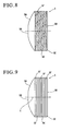
Figures 5 to 9 show other embodiments to which the present invention is applied. In the embodiments, the orientation and shape of theoil grooves 5F are changed. That is, in theshoe 5 shown inFigure 5 ,oil grooves 5F are formed inclined 45 degrees to the axis C such that the inclination direction thereof is opposite to that of the aforementioned first embodiment. - Next, in
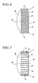
Figure 6 , V-shapedoil grooves 5F are circumferentially formed at equal pitches in the outer peripheral surface of thecylindrical portion 5C. One end of each of the V-shapedoil grooves 5F reaches thespherical portion 5A, and the other end of each of theoil grooves 5F reaches the chamferedportion 5E (the outer peripheral edge of theend surface portion 5B). - Next, in
Figure 7 ,linear oil grooves 5F are formed parallel to the axial direction at equal pitches in the outer peripheral surface of thecylindrical portion 5C. One end of each of theoil grooves 5F reaches thespherical portion 5A, and the other end reaches the chamferedportion 5E (the outer peripheral edge of theend surface portion 5B). - Next, in
Figure 8 , aspiral oil groove 5F is formed in the outer peripheral surface of thecylindrical portion 5C. One end of theoil groove 5F reaches thespherical portion 5A, and the other end reaches the chamferedportion 5E (the outer peripheral edge of theend surface portion 5B).
Theshoe 5 in each of the embodiments shown inFigures 5 to 8 described above is configured such that thespherical portion 5A and theend surface portion 5B, which are the sliding portions, are in communication with each other through theoil groove 5F. That is, when theshoe 5 is moved, the lubricant oil held in theoil groove 5F is fed to thespherical portion 5A and theend surface portion 5B as in the first embodiment shown inFigure 2 .
Although one end of theoil groove 5F reaches thespherical portion 5A and the other end of theoil groove 5F reaches theend surface portion 5B in theshoe 5 in each of the embodiments shown inFigures 2 to 8 , the other end of theoil groove 5F may not reach theend surface portion 5B. That is, in this case, only the one end of theoil groove 5F reaches thespherical portion 5A. - Furthermore, in the
shoe 5 in the embodiment shown inFigure 9 , ring-shapedoil grooves 5F are formed perpendicular to the axis C at equal pitches in the outer peripheral surface of thecylindrical portion 5C. In each of the embodiments shown inFigures 5 to 9 , the sectional shape of theoil groove 5F is the same rectangular sectional shape as that of the aforementioned first embodiment.
The same operation and effect as those of the first embodiment inFigure 2 can be also obtained in each of the embodiments shown inFigures 5 to 9 . - The sectional shape and arrangement density of the
oil grooves 5F in each of the aforementioned embodiments may be changed as shown inFigures 10 . That is, inFigure 10(a) , the sectional shape of theoil groove 5F is a triangular shape, and inFigure 10(b) , the sectional shape of theoil groove 5F is an arc shape. Furthermore,Figures 10(c) to 10(e) show embodiments in which theadjacent oil grooves 5F are arranged as close as possible to each other. - Next,
Figures 11 and 12 show yet other embodiments according to the present invention. In the embodiments, a plurality ofconcave portions 5G are formed in the outer peripheral surface of thecylindrical portion 5C instead of theoil grooves 5F. To be more specific, inFigure 11 , circularconcave portions 5G having the same dimensions as each other are formed in a staggered manner in the outer peripheral surface of thecylindrical portion 5C.
Also, inFigure 12 , squareconcave portions 5G having the same dimensions as each other are formed in the outer peripheral surface of thecylindrical portion 5C. A plurality of triangular or oval concave portions may be also formed in the outer peripheral surface of thecylindrical portion 5C instead of the circular and squareconcave portions 5G.
Theshoe 5 where the plurality ofconcave portions 5G are formed in the outer peripheral surface of thecylindrical portion 5C can also produce the same operation and effect as those of the aforementioned first embodiment. - Next,
Figures 13 to 15 show yet other embodiments according to the present invention. In the embodiments, the shape of thecylindrical portion 5C is changed.
To be more specific, inFigure 13 , thecylindrical portion 5C of theshoe 5 is formed in a tapered shape which is gradually reduced in diameter from theend surface portion 5B toward thespherical portion 5A. The plurality ofoil grooves 5F similar to those of the first embodiment inFigure 2 are formed in the outer peripheral surface of thecylindrical portion 5C having such a tapered shape.
Also, inFigure 14 , thecylindrical portion 5C of theshoe 5 is formed in a tapered shape which is gradually reduced in diameter from thespherical portion 5A toward theend surface portion 5B. Thelinear oil grooves 5F are formed in the outer peripheral surface of thecylindrical portion 5C having such a tapered shape.
Moreover, inFigure 15 , thecylindrical portion 5C has a drum shape whose axial center portion expands outward in the radial direction so as to have a largest outer diameter, and the plurality oflinear oil grooves 5F are formed in the outer peripheral surface.
Theshoe 5 in each of the embodiments shown inFigures 13 to 15 can also produce the same operation and effect as those of the aforementioned first embodiment. In the embodiments ofFigures 13 to 15 , the plurality ofconcave portions 5G shown inFigures 11 and 12 may be also formed in the outer peripheral surface of thecylindrical portion 5C instead of theoil grooves 5F.
Although one end of theoil groove 5F reaches thespherical portion 5A and the other end of theoil groove 5F reaches theend surface portion 5B in theshoe 5 in each of the embodiments shown inFigures 13 to 15 , the other end of theoil groove 5F may not reach theend surface portion 5B. That is, in this case, only the one end of theoil groove 5F reaches thespherical portion 5A. -
Figure 16 further shows yet another embodiment according to the present invention. In the embodiment, aflange portion 5H is formed projecting on the outer peripheral edge of theend surface portion 5B of the first embodiment shown inFigure 2 . Based on the configuration, thelinear oil grooves 5F are formed in the outer peripheral surface of thecylindrical portion 5C of theshoe 5 in a similar manner to the aforementioned first embodiment. The other components in the configuration are the same as those of the first embodiment. Theshoe 5 shown inFigure 16 can also produce the same operation and effect as those of the aforementioned respective embodiments.
Theflange portion 5H may be also provided projecting on the outer peripheral edge of theend surface portion 5B in theshoe 5 according to the embodiment shown in each ofFigures 2 to 9 and11 to 15 in a similar manner toFigure 16 . - Furthermore, grid-like oil grooves may be also provided in the outer peripheral surface of the
cylindrical portion 5C instead of thelinear oil grooves 5F in each of the aforementioned embodiments. Alternatively, both theoil grooves 5F and theconcave portions 5G may be provided in the outer peripheral surface of thecylindrical portion 5C. -
- 3:
- Swash plate (Second movable member)
- 4:
- Piston (First movable member)
- 4a:
- Sliding surface
- 5:
- Shoe
- 5A:
- Spherical portion
- 5B:
- End surface portion
- 5C:
- Cylindrical portion
- 5F:
- Oil groove
- 5G:
- Concave portion
Claims (10)
- A shoe comprising a spherical portion in sliding contact with a hemispherical concave portion of a first movable member, an end surface portion in sliding contact with a flat surface of a second movable member, and a cylindrical portion formed between the spherical portion and the end surface portion,
wherein a groove and/or a concave portion is provided in an outer peripheral surface of the cylindrical portion, and a lubricant oil is held in the groove and/or the concave portion. - The shoe according to claim 1, wherein the cylindrical portion is formed in a circular cylindrical shape having a constant outer diameter over an entire axial length.
- The shoe according to claim 1, wherein the cylindrical portion is formed in a tapered shape where the spherical portion side has a smaller diameter than the end surface portion side.
- The shoe according to claim 1, wherein the cylindrical portion is formed in a tapered shape where the end surface portion side has a smaller diameter than the spherical portion side.
- The shoe according to claim 1, wherein the cylindrical portion has a drum shape where an axial center portion radially expands outward so as to have a largest outer diameter.
- The shoe according to any one of claims 2 to 5, wherein a flange portion is formed radially extending outward on an outer peripheral edge of the end surface portion.
- The shoe according to any one of claims 1 to 6, wherein a plurality of the grooves are provided, and one end of each of the grooves reaches the spherical portion.
- The shoe according to any one of claims 1 to 5, wherein a plurality of the grooves are provided, one end of each of the grooves reaches the spherical portion, and the other end of each of the grooves reaches the end surface portion, the spherical portion and the end surface portion being in communication with each other through the plurality of grooves.
- The shoe according to claim 7 or 8, wherein the grooves have a linear, V, or grid-like shape, and are provided at equal pitches in the outer peripheral surface of the cylindrical portion.
- The shoe according to any one of claims 1 to 6, wherein a plurality of the concave portions are provided, and each of the concave portions has one of circular, square, triangular, and oval shapes.
Applications Claiming Priority (2)
| Application Number | Priority Date | Filing Date | Title |
|---|---|---|---|
| JP2009129223A JP5495622B2 (en) | 2009-05-28 | 2009-05-28 | Shoe |
| PCT/JP2009/070464 WO2010137194A1 (en) | 2009-05-28 | 2009-12-07 | Shoe |
Publications (3)
| Publication Number | Publication Date |
|---|---|
| EP2290239A1 true EP2290239A1 (en) | 2011-03-02 |
| EP2290239A4 EP2290239A4 (en) | 2011-07-27 |
| EP2290239B1 EP2290239B1 (en) | 2019-08-21 |
Family
ID=43222329
Family Applications (1)
| Application Number | Title | Priority Date | Filing Date |
|---|---|---|---|
| EP09843177.8A Active EP2290239B1 (en) | 2009-05-28 | 2009-12-07 | Shoe |
Country Status (7)
| Country | Link |
|---|---|
| US (1) | US9435327B2 (en) |
| EP (1) | EP2290239B1 (en) |
| JP (1) | JP5495622B2 (en) |
| KR (1) | KR101210839B1 (en) |
| CN (1) | CN102066753B (en) |
| BR (1) | BRPI0924062A2 (en) |
| WO (1) | WO2010137194A1 (en) |
Families Citing this family (3)
| Publication number | Priority date | Publication date | Assignee | Title |
|---|---|---|---|---|
| JP5731991B2 (en) * | 2012-01-20 | 2015-06-10 | 大豊工業株式会社 | Sliding member |
| KR101840246B1 (en) * | 2013-10-16 | 2018-03-20 | 가부시키가이샤 고마쓰 세이사쿠쇼 | Sliding component, method for producing sliding component, and device for producing sliding component |
| JP6331043B2 (en) * | 2016-03-18 | 2018-05-30 | 博 小曽戸 | Piston for hydraulic equipment and hydraulic equipment |
Family Cites Families (28)
| Publication number | Priority date | Publication date | Assignee | Title |
|---|---|---|---|---|
| USRE23993E (en) * | 1955-05-03 | Best available copy | ||
| US2022917A (en) * | 1933-05-15 | 1935-12-03 | Michell Crankless Engines Corp | Bearing |
| US2250607A (en) * | 1939-05-27 | 1941-07-29 | Thomas L Sherman | Pivoted bearing element or slipper pad for crankless mechanisms |
| JPS5776281A (en) * | 1980-10-29 | 1982-05-13 | Taiho Kogyo Co Ltd | Shoe for use in swash plate type compressor |
| JPS6026188A (en) * | 1983-07-20 | 1985-02-09 | Taiho Kogyo Co Ltd | Swash plate type compressor |
| US4617856A (en) * | 1986-01-13 | 1986-10-21 | General Motors Corporation | Swash plate compressor having integral shoe and ball |
| US4683803A (en) * | 1986-01-13 | 1987-08-04 | General Motors Corporation | Swash plate compressor having integral shoe and ball |
| DE19653158A1 (en) * | 1995-12-28 | 1997-07-03 | Unisia Jecs Corp | Axial plunger pump |
| JP3803135B2 (en) | 1996-04-09 | 2006-08-02 | 株式会社リケン | Shoe for swash plate compressor |
| JP3942219B2 (en) * | 1996-12-18 | 2007-07-11 | サンデン株式会社 | Swash plate compressor |
| JPH10220347A (en) | 1997-02-10 | 1998-08-18 | Toyota Autom Loom Works Ltd | Variable capacity compressor |
| JP3495225B2 (en) * | 1997-06-25 | 2004-02-09 | サンデン株式会社 | Method of manufacturing shoe for swash plate type compressor |
| JPH1122640A (en) * | 1997-07-08 | 1999-01-26 | Riken Corp | Shoe for swash plate compressor |
| JPH1150959A (en) * | 1997-08-01 | 1999-02-23 | Ntn Corp | Shoe for swash plate type compressor |
| US5983776A (en) * | 1998-11-23 | 1999-11-16 | Sauer Inc. | Two-piece slipper with balanced running face |
| JP2001003858A (en) * | 1999-06-16 | 2001-01-09 | Sanden Corp | Swash plate type compressor |
| JP3259777B2 (en) | 1999-11-26 | 2002-02-25 | 大豊工業株式会社 | Hemispherical shoe |
| JP4388239B2 (en) * | 2001-03-26 | 2009-12-24 | サンデン株式会社 | Swash plate compressor |
| JP3715249B2 (en) * | 2001-04-27 | 2005-11-09 | シャープ株式会社 | Image processing circuit, image display device, and image processing method |
| JP2002332960A (en) * | 2001-05-10 | 2002-11-22 | Toyota Industries Corp | Method of manufacturing shoe |
| US6895855B2 (en) * | 2001-10-01 | 2005-05-24 | The Timken Company | Hydraulic motors and pumps with engineered surfaces |
| US6555777B1 (en) * | 2002-01-11 | 2003-04-29 | Sauer-Danfoss Inc. | Method of manufacturing bimetal slippers |
| KR100679909B1 (en) * | 2003-09-02 | 2007-02-07 | 가부시키가이샤 도요다 지도숏키 | Swash plate compressor |
| JP2006266141A (en) * | 2005-03-23 | 2006-10-05 | Sanden Corp | Reciprocating fluid machine |
| CN2874054Y (en) * | 2005-11-24 | 2007-02-28 | 沈一中 | slide shoe for compressor |
| DE102006008437A1 (en) * | 2006-02-23 | 2007-10-04 | Schaeffler Kg | Sliding shoe for a swash plate gear |
| US7313997B2 (en) * | 2006-05-26 | 2008-01-01 | Visteon Global Technologies, Inc. | Copper alloy piston shoe |
| JP4844367B2 (en) * | 2006-11-30 | 2011-12-28 | 株式会社豊田自動織機 | Spherical crown shoe |
-
2009
- 2009-05-28 JP JP2009129223A patent/JP5495622B2/en active Active
- 2009-12-07 BR BRPI0924062-4A patent/BRPI0924062A2/en not_active Application Discontinuation
- 2009-12-07 KR KR1020107017842A patent/KR101210839B1/en active Active
- 2009-12-07 CN CN200980109934.6A patent/CN102066753B/en active Active
- 2009-12-07 EP EP09843177.8A patent/EP2290239B1/en active Active
- 2009-12-07 WO PCT/JP2009/070464 patent/WO2010137194A1/en not_active Ceased
- 2009-12-07 US US12/735,670 patent/US9435327B2/en active Active
Also Published As
| Publication number | Publication date |
|---|---|
| CN102066753B (en) | 2014-01-08 |
| US9435327B2 (en) | 2016-09-06 |
| EP2290239B1 (en) | 2019-08-21 |
| KR101210839B1 (en) | 2012-12-11 |
| EP2290239A4 (en) | 2011-07-27 |
| BRPI0924062A2 (en) | 2018-09-11 |
| JP2010275927A (en) | 2010-12-09 |
| CN102066753A (en) | 2011-05-18 |
| JP5495622B2 (en) | 2014-05-21 |
| KR20110036694A (en) | 2011-04-08 |
| WO2010137194A1 (en) | 2010-12-02 |
| US20110107908A1 (en) | 2011-05-12 |
Similar Documents
| Publication | Publication Date | Title |
|---|---|---|
| JP5767959B2 (en) | Sliding member | |
| EP3502496B1 (en) | Half thrust bearing | |
| KR20150132079A (en) | Thrust washer | |
| CN117469129A (en) | Reciprocating compressors and refrigeration equipment | |
| EP2290239A1 (en) | Shoe | |
| US20130084195A1 (en) | Swash plate compressor | |
| KR101501277B1 (en) | Sliding member | |
| CN219932391U (en) | Reciprocating compressors and refrigeration equipment | |
| JP2005069215A (en) | Piston | |
| KR101185812B1 (en) | Swash plate compressor | |
| JP5771266B2 (en) | Shoe | |
| KR100274968B1 (en) | Reciprocating compressor | |
| EP1898090A2 (en) | Variable displacement compressor | |
| JP2004300926A (en) | Swash plate compressor | |
| JP2001317453A (en) | Swash plate type compressor | |
| EP3698059B1 (en) | A single-piece turbo bearing | |
| KR100887233B1 (en) | Inclined plate for compressor and its coating method | |
| JP2004316452A (en) | Reciprocating compressor | |
| JPS63173862A (en) | Rotary swash plate type compressor having main shaft supported in cantilever form | |
| US20100232987A1 (en) | Variable displacement inclined plate type compressor | |
| JP2018059414A (en) | Compressor swash plate | |
| JP2007205315A (en) | Swash plate of swash plate compressor and swash plate compressor | |
| JPS63173857A (en) | Rotary swash plate type compressor having main shaft supported in cantilever form |
Legal Events
| Date | Code | Title | Description |
|---|---|---|---|
| PUAI | Public reference made under article 153(3) epc to a published international application that has entered the european phase |
Free format text: ORIGINAL CODE: 0009012 |
|
| 17P | Request for examination filed |
Effective date: 20101015 |
|
| AK | Designated contracting states |
Kind code of ref document: A1 Designated state(s): AT BE BG CH CY CZ DE DK EE ES FI FR GB GR HR HU IE IS IT LI LT LU LV MC MK MT NL NO PL PT RO SE SI SK SM TR |
|
| RIN1 | Information on inventor provided before grant (corrected) |
Inventor name: NOMURA, SATOSHI Inventor name: HATTA, MASAHARU |
|
| A4 | Supplementary search report drawn up and despatched |
Effective date: 20110624 |
|
| DAX | Request for extension of the european patent (deleted) | ||
| 17Q | First examination report despatched |
Effective date: 20151130 |
|
| STAA | Information on the status of an ep patent application or granted ep patent |
Free format text: STATUS: EXAMINATION IS IN PROGRESS |
|
| GRAP | Despatch of communication of intention to grant a patent |
Free format text: ORIGINAL CODE: EPIDOSNIGR1 |
|
| STAA | Information on the status of an ep patent application or granted ep patent |
Free format text: STATUS: GRANT OF PATENT IS INTENDED |
|
| INTG | Intention to grant announced |
Effective date: 20190327 |
|
| GRAS | Grant fee paid |
Free format text: ORIGINAL CODE: EPIDOSNIGR3 |
|
| GRAA | (expected) grant |
Free format text: ORIGINAL CODE: 0009210 |
|
| STAA | Information on the status of an ep patent application or granted ep patent |
Free format text: STATUS: THE PATENT HAS BEEN GRANTED |
|
| AK | Designated contracting states |
Kind code of ref document: B1 Designated state(s): AT BE BG CH CY CZ DE DK EE ES FI FR GB GR HR HU IE IS IT LI LT LU LV MC MK MT NL NO PL PT RO SE SI SK SM TR |
|
| REG | Reference to a national code |
Ref country code: GB Ref legal event code: FG4D |
|
| REG | Reference to a national code |
Ref country code: CH Ref legal event code: EP |
|
| REG | Reference to a national code |
Ref country code: DE Ref legal event code: R096 Ref document number: 602009059576 Country of ref document: DE |
|
| REG | Reference to a national code |
Ref country code: AT Ref legal event code: REF Ref document number: 1170061 Country of ref document: AT Kind code of ref document: T Effective date: 20190915 |
|
| REG | Reference to a national code |
Ref country code: IE Ref legal event code: FG4D |
|
| REG | Reference to a national code |
Ref country code: LT Ref legal event code: MG4D |
|
| REG | Reference to a national code |
Ref country code: NL Ref legal event code: MP Effective date: 20190821 |
|
| PG25 | Lapsed in a contracting state [announced via postgrant information from national office to epo] |
Ref country code: BG Free format text: LAPSE BECAUSE OF FAILURE TO SUBMIT A TRANSLATION OF THE DESCRIPTION OR TO PAY THE FEE WITHIN THE PRESCRIBED TIME-LIMIT Effective date: 20191121 Ref country code: NO Free format text: LAPSE BECAUSE OF FAILURE TO SUBMIT A TRANSLATION OF THE DESCRIPTION OR TO PAY THE FEE WITHIN THE PRESCRIBED TIME-LIMIT Effective date: 20191121 Ref country code: FI Free format text: LAPSE BECAUSE OF FAILURE TO SUBMIT A TRANSLATION OF THE DESCRIPTION OR TO PAY THE FEE WITHIN THE PRESCRIBED TIME-LIMIT Effective date: 20190821 Ref country code: LT Free format text: LAPSE BECAUSE OF FAILURE TO SUBMIT A TRANSLATION OF THE DESCRIPTION OR TO PAY THE FEE WITHIN THE PRESCRIBED TIME-LIMIT Effective date: 20190821 Ref country code: NL Free format text: LAPSE BECAUSE OF FAILURE TO SUBMIT A TRANSLATION OF THE DESCRIPTION OR TO PAY THE FEE WITHIN THE PRESCRIBED TIME-LIMIT Effective date: 20190821 Ref country code: SE Free format text: LAPSE BECAUSE OF FAILURE TO SUBMIT A TRANSLATION OF THE DESCRIPTION OR TO PAY THE FEE WITHIN THE PRESCRIBED TIME-LIMIT Effective date: 20190821 Ref country code: HR Free format text: LAPSE BECAUSE OF FAILURE TO SUBMIT A TRANSLATION OF THE DESCRIPTION OR TO PAY THE FEE WITHIN THE PRESCRIBED TIME-LIMIT Effective date: 20190821 Ref country code: PT Free format text: LAPSE BECAUSE OF FAILURE TO SUBMIT A TRANSLATION OF THE DESCRIPTION OR TO PAY THE FEE WITHIN THE PRESCRIBED TIME-LIMIT Effective date: 20191223 |
|
| PG25 | Lapsed in a contracting state [announced via postgrant information from national office to epo] |
Ref country code: LV Free format text: LAPSE BECAUSE OF FAILURE TO SUBMIT A TRANSLATION OF THE DESCRIPTION OR TO PAY THE FEE WITHIN THE PRESCRIBED TIME-LIMIT Effective date: 20190821 Ref country code: GR Free format text: LAPSE BECAUSE OF FAILURE TO SUBMIT A TRANSLATION OF THE DESCRIPTION OR TO PAY THE FEE WITHIN THE PRESCRIBED TIME-LIMIT Effective date: 20191122 Ref country code: IS Free format text: LAPSE BECAUSE OF FAILURE TO SUBMIT A TRANSLATION OF THE DESCRIPTION OR TO PAY THE FEE WITHIN THE PRESCRIBED TIME-LIMIT Effective date: 20191221 |
|
| REG | Reference to a national code |
Ref country code: AT Ref legal event code: MK05 Ref document number: 1170061 Country of ref document: AT Kind code of ref document: T Effective date: 20190821 |
|
| PG25 | Lapsed in a contracting state [announced via postgrant information from national office to epo] |
Ref country code: TR Free format text: LAPSE BECAUSE OF FAILURE TO SUBMIT A TRANSLATION OF THE DESCRIPTION OR TO PAY THE FEE WITHIN THE PRESCRIBED TIME-LIMIT Effective date: 20190821 |
|
| PG25 | Lapsed in a contracting state [announced via postgrant information from national office to epo] |
Ref country code: IT Free format text: LAPSE BECAUSE OF FAILURE TO SUBMIT A TRANSLATION OF THE DESCRIPTION OR TO PAY THE FEE WITHIN THE PRESCRIBED TIME-LIMIT Effective date: 20190821 Ref country code: DK Free format text: LAPSE BECAUSE OF FAILURE TO SUBMIT A TRANSLATION OF THE DESCRIPTION OR TO PAY THE FEE WITHIN THE PRESCRIBED TIME-LIMIT Effective date: 20190821 Ref country code: AT Free format text: LAPSE BECAUSE OF FAILURE TO SUBMIT A TRANSLATION OF THE DESCRIPTION OR TO PAY THE FEE WITHIN THE PRESCRIBED TIME-LIMIT Effective date: 20190821 Ref country code: EE Free format text: LAPSE BECAUSE OF FAILURE TO SUBMIT A TRANSLATION OF THE DESCRIPTION OR TO PAY THE FEE WITHIN THE PRESCRIBED TIME-LIMIT Effective date: 20190821 Ref country code: PL Free format text: LAPSE BECAUSE OF FAILURE TO SUBMIT A TRANSLATION OF THE DESCRIPTION OR TO PAY THE FEE WITHIN THE PRESCRIBED TIME-LIMIT Effective date: 20190821 Ref country code: RO Free format text: LAPSE BECAUSE OF FAILURE TO SUBMIT A TRANSLATION OF THE DESCRIPTION OR TO PAY THE FEE WITHIN THE PRESCRIBED TIME-LIMIT Effective date: 20190821 |
|
| PG25 | Lapsed in a contracting state [announced via postgrant information from national office to epo] |
Ref country code: IS Free format text: LAPSE BECAUSE OF FAILURE TO SUBMIT A TRANSLATION OF THE DESCRIPTION OR TO PAY THE FEE WITHIN THE PRESCRIBED TIME-LIMIT Effective date: 20200224 Ref country code: CZ Free format text: LAPSE BECAUSE OF FAILURE TO SUBMIT A TRANSLATION OF THE DESCRIPTION OR TO PAY THE FEE WITHIN THE PRESCRIBED TIME-LIMIT Effective date: 20190821 Ref country code: SM Free format text: LAPSE BECAUSE OF FAILURE TO SUBMIT A TRANSLATION OF THE DESCRIPTION OR TO PAY THE FEE WITHIN THE PRESCRIBED TIME-LIMIT Effective date: 20190821 Ref country code: SK Free format text: LAPSE BECAUSE OF FAILURE TO SUBMIT A TRANSLATION OF THE DESCRIPTION OR TO PAY THE FEE WITHIN THE PRESCRIBED TIME-LIMIT Effective date: 20190821 |
|
| REG | Reference to a national code |
Ref country code: DE Ref legal event code: R097 Ref document number: 602009059576 Country of ref document: DE |
|
| PLBE | No opposition filed within time limit |
Free format text: ORIGINAL CODE: 0009261 |
|
| STAA | Information on the status of an ep patent application or granted ep patent |
Free format text: STATUS: NO OPPOSITION FILED WITHIN TIME LIMIT |
|
| PG2D | Information on lapse in contracting state deleted |
Ref country code: IS |
|
| REG | Reference to a national code |
Ref country code: CH Ref legal event code: PL |
|
| 26N | No opposition filed |
Effective date: 20200603 |
|
| REG | Reference to a national code |
Ref country code: BE Ref legal event code: MM Effective date: 20191231 |
|
| PG25 | Lapsed in a contracting state [announced via postgrant information from national office to epo] |
Ref country code: SI Free format text: LAPSE BECAUSE OF FAILURE TO SUBMIT A TRANSLATION OF THE DESCRIPTION OR TO PAY THE FEE WITHIN THE PRESCRIBED TIME-LIMIT Effective date: 20190821 Ref country code: MC Free format text: LAPSE BECAUSE OF FAILURE TO SUBMIT A TRANSLATION OF THE DESCRIPTION OR TO PAY THE FEE WITHIN THE PRESCRIBED TIME-LIMIT Effective date: 20190821 |
|
| GBPC | Gb: european patent ceased through non-payment of renewal fee |
Effective date: 20191207 |
|
| PG25 | Lapsed in a contracting state [announced via postgrant information from national office to epo] |
Ref country code: GB Free format text: LAPSE BECAUSE OF NON-PAYMENT OF DUE FEES Effective date: 20191207 Ref country code: FR Free format text: LAPSE BECAUSE OF NON-PAYMENT OF DUE FEES Effective date: 20191231 Ref country code: IE Free format text: LAPSE BECAUSE OF NON-PAYMENT OF DUE FEES Effective date: 20191207 Ref country code: LU Free format text: LAPSE BECAUSE OF NON-PAYMENT OF DUE FEES Effective date: 20191207 Ref country code: ES Free format text: LAPSE BECAUSE OF FAILURE TO SUBMIT A TRANSLATION OF THE DESCRIPTION OR TO PAY THE FEE WITHIN THE PRESCRIBED TIME-LIMIT Effective date: 20190821 |
|
| PG25 | Lapsed in a contracting state [announced via postgrant information from national office to epo] |
Ref country code: CH Free format text: LAPSE BECAUSE OF NON-PAYMENT OF DUE FEES Effective date: 20191231 Ref country code: LI Free format text: LAPSE BECAUSE OF NON-PAYMENT OF DUE FEES Effective date: 20191231 Ref country code: BE Free format text: LAPSE BECAUSE OF NON-PAYMENT OF DUE FEES Effective date: 20191231 |
|
| PG25 | Lapsed in a contracting state [announced via postgrant information from national office to epo] |
Ref country code: CY Free format text: LAPSE BECAUSE OF FAILURE TO SUBMIT A TRANSLATION OF THE DESCRIPTION OR TO PAY THE FEE WITHIN THE PRESCRIBED TIME-LIMIT Effective date: 20190821 |
|
| PG25 | Lapsed in a contracting state [announced via postgrant information from national office to epo] |
Ref country code: HU Free format text: LAPSE BECAUSE OF FAILURE TO SUBMIT A TRANSLATION OF THE DESCRIPTION OR TO PAY THE FEE WITHIN THE PRESCRIBED TIME-LIMIT; INVALID AB INITIO Effective date: 20091207 Ref country code: MT Free format text: LAPSE BECAUSE OF FAILURE TO SUBMIT A TRANSLATION OF THE DESCRIPTION OR TO PAY THE FEE WITHIN THE PRESCRIBED TIME-LIMIT Effective date: 20190821 |
|
| PG25 | Lapsed in a contracting state [announced via postgrant information from national office to epo] |
Ref country code: MK Free format text: LAPSE BECAUSE OF FAILURE TO SUBMIT A TRANSLATION OF THE DESCRIPTION OR TO PAY THE FEE WITHIN THE PRESCRIBED TIME-LIMIT Effective date: 20190821 |
|
| PGFP | Annual fee paid to national office [announced via postgrant information from national office to epo] |
Ref country code: DE Payment date: 20251028 Year of fee payment: 17 |