EP2290231B1 - System and method for updating formula in wind turbines controllers - Google Patents
System and method for updating formula in wind turbines controllers Download PDFInfo
- Publication number
- EP2290231B1 EP2290231B1 EP10173574.4A EP10173574A EP2290231B1 EP 2290231 B1 EP2290231 B1 EP 2290231B1 EP 10173574 A EP10173574 A EP 10173574A EP 2290231 B1 EP2290231 B1 EP 2290231B1
- Authority
- EP
- European Patent Office
- Prior art keywords
- wind turbine
- controller
- formula
- user interface
- operational data
- Prior art date
- Legal status (The legal status is an assumption and is not a legal conclusion. Google has not performed a legal analysis and makes no representation as to the accuracy of the status listed.)
- Active
Links
- 238000000034 method Methods 0.000 title description 15
- 238000012544 monitoring process Methods 0.000 claims description 13
- 230000000007 visual effect Effects 0.000 claims description 3
- 238000007726 management method Methods 0.000 description 7
- 230000006870 function Effects 0.000 description 5
- 230000005611 electricity Effects 0.000 description 4
- 238000010586 diagram Methods 0.000 description 3
- 230000005055 memory storage Effects 0.000 description 3
- 230000004044 response Effects 0.000 description 3
- 238000004458 analytical method Methods 0.000 description 2
- 238000004364 calculation method Methods 0.000 description 2
- 230000008859 change Effects 0.000 description 2
- 238000013500 data storage Methods 0.000 description 2
- 238000004519 manufacturing process Methods 0.000 description 2
- 238000005259 measurement Methods 0.000 description 2
- 230000008569 process Effects 0.000 description 2
- 230000008901 benefit Effects 0.000 description 1
- 230000002860 competitive effect Effects 0.000 description 1
- 230000000694 effects Effects 0.000 description 1
- 238000012986 modification Methods 0.000 description 1
- 230000004048 modification Effects 0.000 description 1
- 238000012545 processing Methods 0.000 description 1
Images


Classifications
-
- F—MECHANICAL ENGINEERING; LIGHTING; HEATING; WEAPONS; BLASTING
- F03—MACHINES OR ENGINES FOR LIQUIDS; WIND, SPRING, OR WEIGHT MOTORS; PRODUCING MECHANICAL POWER OR A REACTIVE PROPULSIVE THRUST, NOT OTHERWISE PROVIDED FOR
- F03D—WIND MOTORS
- F03D7/00—Controlling wind motors
- F03D7/02—Controlling wind motors the wind motors having rotation axis substantially parallel to the air flow entering the rotor
- F03D7/04—Automatic control; Regulation
- F03D7/042—Automatic control; Regulation by means of an electrical or electronic controller
- F03D7/047—Automatic control; Regulation by means of an electrical or electronic controller characterised by the controller architecture, e.g. multiple processors or data communications
-
- F—MECHANICAL ENGINEERING; LIGHTING; HEATING; WEAPONS; BLASTING
- F03—MACHINES OR ENGINES FOR LIQUIDS; WIND, SPRING, OR WEIGHT MOTORS; PRODUCING MECHANICAL POWER OR A REACTIVE PROPULSIVE THRUST, NOT OTHERWISE PROVIDED FOR
- F03D—WIND MOTORS
- F03D17/00—Monitoring or testing of wind motors, e.g. diagnostics
-
- G—PHYSICS
- G05—CONTROLLING; REGULATING
- G05B—CONTROL OR REGULATING SYSTEMS IN GENERAL; FUNCTIONAL ELEMENTS OF SUCH SYSTEMS; MONITORING OR TESTING ARRANGEMENTS FOR SUCH SYSTEMS OR ELEMENTS
- G05B15/00—Systems controlled by a computer
- G05B15/02—Systems controlled by a computer electric
-
- Y—GENERAL TAGGING OF NEW TECHNOLOGICAL DEVELOPMENTS; GENERAL TAGGING OF CROSS-SECTIONAL TECHNOLOGIES SPANNING OVER SEVERAL SECTIONS OF THE IPC; TECHNICAL SUBJECTS COVERED BY FORMER USPC CROSS-REFERENCE ART COLLECTIONS [XRACs] AND DIGESTS
- Y02—TECHNOLOGIES OR APPLICATIONS FOR MITIGATION OR ADAPTATION AGAINST CLIMATE CHANGE
- Y02E—REDUCTION OF GREENHOUSE GAS [GHG] EMISSIONS, RELATED TO ENERGY GENERATION, TRANSMISSION OR DISTRIBUTION
- Y02E10/00—Energy generation through renewable energy sources
- Y02E10/70—Wind energy
- Y02E10/72—Wind turbines with rotation axis in wind direction
Definitions
- the field of the invention relates generally to wind turbines and, more specifically, to management systems used with wind turbines, including supervisory control and data acquisition (SCADA) systems.
- SCADA supervisory control and data acquisition
- Wind turbine generators use wind energy to generate electricity and are becoming increasingly more important in terms of a renewable source of generating electricity.
- a wind turbine farm that includes multiple wind turbines, is often managed by a SCADA system that monitors data received from sensors coupled to the wind turbines.
- SCADA systems calculate various parameters, such as 'lost production,' 'site power,' 'site wind speed,' and 'site availability,' based on the sensor data and using algorithms programmed into the SCADA system.
- SCADA When an operator of the SCADA system wants to implement new formulas to calculate additional parameters, or wants to modify the formulas programmed into the SCADA system, generally new or replacement software must be installed while the SCADA system is in a non-operating mode.
- FIG. 1 is a side perspective view of an exemplary wind turbine 100.
- wind turbine 100 is a horizontal axis wind turbine generator.
- wind turbine 100 may be a vertical axis wind turbine generator.
- the terms "wind turbine' and "wind turbine generator” are used interchangeably, and are representative of any device that converts wind energy to electrical energy and, more specifically, converts kinetic energy of wind into mechanical energy that generates electricity using a generator.
- Wind turbine 100 includes a rotor 102 that includes a plurality of rotor blades 104 coupled to a rotatable hub 106.
- Wind turbine 100 also includes a nacelle 107 that houses a generator 108 therein and that is coupled to rotatable hub 106.
- rotor 102 includes three rotor blades 104.
- rotor 102 may include any suitable number of rotor blades 104 that enables wind turbine 100 to function as described herein.
- generator 108 is coupled to a support tower 110 that supports wind turbine 100 during operation.
- wind turbine 100 includes a gearbox (not shown) that is rotatably coupled to rotatable hub 106 and generator 108.
- wind forces act upon rotor blades 104 causing rotor 102 to rotate about an axis 112 of generator 108 of wind turbine 100 and to generate electrical power.
- stresses created by the force of the wind upon rotor blades 104, hub 106, generator portion 108, and support tower 110, as well as operational parameters such as power output and temperature, are measured by sensors 204 (shown in Figure 2 ) and/or determined by at least one programmable logic controller (PLC) 205, and the resulting measured and/or determined operational data, is transmitted to a wind formulary system 200 (shown in Figure 2 ).
- PLC programmable logic controller
- aspects and embodiments of the methods, systems, and controller described herein include: at least one of receiving operational data and/or identifying information; selecting a formula; determining at least one site level parameter, storing operational data, identifying information, and/or determined parameters; and, outputting operation data and/or determined parameters.
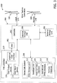
- Figures 2 and 3 are block diagrams illustrating an exemplary wind formulary system for use in monitoring an operating wind turbine 100 that includes identifying information to uniquely identify each operating wind turbine 100.
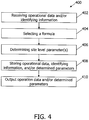
- Figure 4 is a flowchart of an exemplary method 400 for monitoring an operating wind turbine 100.
- wind formulary system 200 includes an exemplary controller 202 for use in monitoring an operating wind turbine 100 that includes identifying information to uniquely identify each operating wind turbine 100.
- wind formulary system controller 202 includes a memory storage unit 206 that stores information and data used by controller 202 to operate, to retrieve, and/or to store operational data, identifying information, formulas, and/or site level parameters related to wind turbine 100.
- memory storage unit 206 may include internal and/or external storage such as a hard drive, Read Only Memory (ROM), Random Access Memory (RAM), or any other suitable device known to those skilled in the art and guided by the teachings herein provided for performing the functions as described herein.
- controller refers to a central processing unit, a microprocessor, a microcontroller, a microcomputer, a reduced instruction set circuit (RISC), an application specific integrated circuit (ASIC), a programmable logic controller, and any other circuit, combination of circuits, and devices known to one skilled in the art and guided by the teachings herein provided that is capable of being used as described herein.
- RISC reduced instruction set circuit
- ASIC application specific integrated circuit
- programmable logic controller any other circuit, combination of circuits, and devices known to one skilled in the art and guided by the teachings herein provided that is capable of being used as described herein.
- controller 202 is communicatively coupled to at least one operating wind turbine 100, to a server sub-system 208, and to a user interface device 210 that includes an input and an output.
- server sub-system 208 includes a data storage unit 212 and a database unit 214.
- data storage unit 214 and database unit 214 receive data from controller 202, store the received data, receive requests for stored data, and/or retrieve stored data in response to the received requests.
- controller 202 is communicatively coupled to a SCADA system which acquires the operational data from the at least one operating wind turbine 100 and transmits the operational data to controller 202.
- database unit 214 stores and retrieves data based on requests received from controller 202 for data stored in one or more databases, such as in a historical data database 215, in an operational data database 216, and in a configuration and formula database 218 that includes configuration data and formulas for use with wind turbine 100.
- user interface device 210 outputs and receives data via a user output device 220 and a user input device 222 respectively.
- controller 202 receives operational data from operating wind turbine 100, wherein the operational data includes data from sensors 204 and/or PLC 205, such as measurements representative of the present operational status of various components of wind turbine 100.
- the operational data may include, or be indicative of, temperature of various components of wind turbine 100, the power output of generator 108, the stresses or forces acting upon various components of wind turbine 100, and/or any other suitable measurements known to those skilled in the art and guided by the teachings herein.
- controller 202 selects at least one formula that is based on the received operational data.
- controller 202 may select a predetermined formula from internal memory storage unit 206, may select a formula via user interface 210, and/or may select a formula via server sub-system 208.
- the formula is selected from at least one formula previously received from a user via user input device 222.
- the formula may automatically be selected based on the received operational.
- controller 202 may automatically select one formula for use during normal operations, and another formula for use during high temperature, high current, and/or high wind operations.
- controller 202 may automatically select a formula based on either a predetermined trigger specified by an operator of controller 202, or controller 202 may automatically select a formula based on analysis of the received operational data and/or data contained in historical data database 215.
- controller 202 determines at least one site level parameter based on received operational data, and transmits the operational data and/or the formula to server sub-system 208.
- controller 202 outputs the operational data and/or the at least one site level parameter via user interface 210.
- user interface 210 outputs the operational data and/or the at least one site level parameter via user output device 220 using at least one of a visual display, a graphical user interface, a hardcopy device, and/or an audio device.
- the selected formula may be applied, in real-time, and used in determining the at least one site level parameter, thus enabling an operator of wind formulary system 200 to create and/or modify the formulas being used to monitor and/or analyze the operations of wind turbine 100 during operation of wind turbine 100 and in real-time.
- selecting a formula via server sub-system 208 includes transmitting operational data and/or wind turbine identifying information to server sub-system 208, transmitting a request to server sub-system 208 for at least one formula based on the operational data and/or the identifying information, and receiving at least one formula from server sub-system 208 in response to the request. Further, in addition to the operation of controller 202 using operational data, in the exemplary embodiment, controller 202 also transmits, to server sub-system, requests for historical data associated with wind turbine 100, and receives historical data in response to such requests.
- controller 202 determines at least one site level parameter using the previously selected formula, based on the received historical data, transmits the determined site level parameter to server sub-system 208, and transmits the historical data, selected formula, and the determined site level parameter to a user using user output device 220 via user interface 210.
- wind turbine management system 300 includes wind formulary system 200.
- Wind turbine management system 300 also includes user interface device 210 that receives input from a user 302 via a graphical user interface 304 and that receives input from other than user 302 via user input device 222.
- controller 202 is coupled to an external storage unit 306 for storage and retrieval of operational data, identifying information, and/or formulas similar to the function of internal storage unit 206.
- wind turbine management system 300 enables user 302 to amass a plurality of formulas for use in monitoring operating wind turbine 100.
- Wind turbine management system 300 is communicatively coupled to an operating wind turbine 308 that is located remotely from wind turbine 100.
- the ability of wind turbine management system 300 to monitor remote operating wind turbine 308 in the same manner as system 300 monitors local operating wind turbine 100 enables an operator to monitor wind turbine farms, during operation, that are remotely located from wind turbine management system 300.
- Such a feature enables centralized monitoring of multiple disparate wind turbine farms, in such an embodiment.
- method 400 includes receiving 402 operational data and/or identifying information from at least one operating wind turbine 100. It should be noted that the identifying information is used to uniquely identify each respective wind turbine 100.
- the method also includes selecting 404 at least one formula based on the received operational data and the identifying information, wherein the selecting 404 process includes selecting a predetermined formula, selecting a formula via user interface device 304, and/or selecting a formula via server sub-system 208.
- the method 400 Upon selecting 404 the formula, in the exemplary embodiment, the method 400 also includes determining 406 at least one site level parameter using the selected formula, and based on the operational data and/or the identifying information, and storing 408 the operational data, the selected at least one formula, the identifying information, and/or the determined at least one site level parameter via server sub-system 208. Furthermore, in the exemplary embodiment, method 400 includes outputting 410 the operational data, the selected at least one formula, and/or the determined at least one site level parameter via user interface device 210.
- selecting 404 a formula includes selecting a formula received previously via user input device 222 of user interface device 210.
- selecting 404 a formula includes selecting a formula that is based on historical data requested and received from server sub-system 208, wherein the historical data includes operational data previously received from wind turbine 100 and/or other similar devices.
- Exemplary embodiments of a wind turbine formulary system and method for monitoring an operating wind turbine using the system are described above in detail.
- the system may be used to create, modify, and/or apply, the formulas used to monitor wind turbines in real-time while the wind turbine is operating, rather than requiring the monitoring system to be shutdown, reinstalled, or restarted during such a formula change/update process.
- the system provides methods to create and/or modify a set of formulas that can be applied to historical data, i.e. previously collected and stored data, in order to generate data intelligence reports from an operational and revenue point of view.
- the formulas can be used to perform calculations on operational data received from individual wind turbines as well as wind farms that include multiple wind turbines.
- Such a system enables live real-time results of calculations using the formulas to be available to other systems and provides a method to save the calculated data as historical data and for further analysis to ease the operational variability in the power production from wind turbines and/or wind farms.
- the system as described herein, may be used to monitor one or more operating wind turbines used to drive mechanical loads as opposed to generating electricity, and thus are not limited to practice with only the methods and systems as described herein. Rather, the exemplary embodiment can be implemented and utilized in connection with many wind turbine applications.
- the wind formulary system as described herein, may be operated independently of, or in cooperation with, a SCADA system.
Description
- The field of the invention relates generally to wind turbines and, more specifically, to management systems used with wind turbines, including supervisory control and data acquisition (SCADA) systems.
- Wind turbine generators use wind energy to generate electricity and are becoming increasingly more important in terms of a renewable source of generating electricity. A wind turbine farm, that includes multiple wind turbines, is often managed by a SCADA system that monitors data received from sensors coupled to the wind turbines. Known SCADA systems calculate various parameters, such as 'lost production,' 'site power,' 'site wind speed,' and 'site availability,' based on the sensor data and using algorithms programmed into the SCADA system. When an operator of the SCADA system wants to implement new formulas to calculate additional parameters, or wants to modify the formulas programmed into the SCADA system, generally new or replacement software must be installed while the SCADA system is in a non-operating mode. Moreover, if an operator wanted to apply new or modified formulas to only a specific wind turbine or group of wind turbines, updated software components often must be installed as well. Because the SCADA system is non-functional while being upgraded with new or replacement software that includes the new or modified formulas, the system is unable to perform its SCADA functions and the wind turbine farm may be susceptible to damage because of the lack of monitoring and control.
- Various conventional systems are described by
WO 01/77525 A1 WO 01/91279 A1 - Accordingly, the ability to add or modify the SCADA system while the system is operating, without the need to update or replace the software could provide a competitive advantage over systems that do not include such capabilities.
- Various aspects and embodiments of the present invention are defined by the appended claims.
- Various aspects and embodiments of the present invention will now be described in connection with the accompanying drawings, in which:
-
Figure 1 is a side perspective view of an exemplary wind turbine. -
Figure 2 is a block diagram illustrating an exemplary SCADA system that includes a controller for use in a wind formulary for monitoring an operating wind turbine. -
Figure 3 is a block diagram illustrating an exemplary wind formulary system that may be used with the SCADA system shown inFigure 2 . -
Figure 4 is a flowchart of an exemplary method for use in monitoring an operating wind turbine. -
Figure 1 is a side perspective view of anexemplary wind turbine 100. In the exemplary embodiment,wind turbine 100 is a horizontal axis wind turbine generator. In an alternative embodiment,wind turbine 100 may be a vertical axis wind turbine generator. As used herein, the terms "wind turbine' and "wind turbine generator" are used interchangeably, and are representative of any device that converts wind energy to electrical energy and, more specifically, converts kinetic energy of wind into mechanical energy that generates electricity using a generator.Wind turbine 100 includes arotor 102 that includes a plurality ofrotor blades 104 coupled to arotatable hub 106.Wind turbine 100 also includes anacelle 107 that houses agenerator 108 therein and that is coupled torotatable hub 106. In the exemplary embodiment,rotor 102 includes threerotor blades 104. Alternatively,rotor 102 may include any suitable number ofrotor blades 104 that enableswind turbine 100 to function as described herein. In the exemplary embodiment,generator 108 is coupled to asupport tower 110 that supportswind turbine 100 during operation. In the exemplary embodiment,wind turbine 100 includes a gearbox (not shown) that is rotatably coupled torotatable hub 106 andgenerator 108. - In the exemplary embodiment, wind forces act upon
rotor blades 104 causingrotor 102 to rotate about anaxis 112 ofgenerator 108 ofwind turbine 100 and to generate electrical power. In the exemplary embodiment, stresses created by the force of the wind uponrotor blades 104,hub 106,generator portion 108, andsupport tower 110, as well as operational parameters such as power output and temperature, are measured by sensors 204 (shown inFigure 2 ) and/or determined by at least one programmable logic controller (PLC) 205, and the resulting measured and/or determined operational data, is transmitted to a wind formulary system 200 (shown inFigure 2 ). - Various technical effects of aspects and embodiments of the methods, systems, and controller described herein include: at least one of receiving operational data and/or identifying information; selecting a formula; determining at least one site level parameter, storing operational data, identifying information, and/or determined parameters; and, outputting operation data and/or determined parameters.
-
Figures 2 and3 are block diagrams illustrating an exemplary wind formulary system for use in monitoring anoperating wind turbine 100 that includes identifying information to uniquely identify eachoperating wind turbine 100.Figure 4 is a flowchart of anexemplary method 400 for monitoring anoperating wind turbine 100. - In the exemplary embodiment, as shown in
Figure 2 ,wind formulary system 200 includes anexemplary controller 202 for use in monitoring anoperating wind turbine 100 that includes identifying information to uniquely identify eachoperating wind turbine 100. In the exemplary embodiment, windformulary system controller 202 includes amemory storage unit 206 that stores information and data used bycontroller 202 to operate, to retrieve, and/or to store operational data, identifying information, formulas, and/or site level parameters related towind turbine 100. In various embodiments,memory storage unit 206 may include internal and/or external storage such as a hard drive, Read Only Memory (ROM), Random Access Memory (RAM), or any other suitable device known to those skilled in the art and guided by the teachings herein provided for performing the functions as described herein. As used herein, the term "controller" refers to a central processing unit, a microprocessor, a microcontroller, a microcomputer, a reduced instruction set circuit (RISC), an application specific integrated circuit (ASIC), a programmable logic controller, and any other circuit, combination of circuits, and devices known to one skilled in the art and guided by the teachings herein provided that is capable of being used as described herein. - In the exemplary embodiment,
controller 202 is communicatively coupled to at least oneoperating wind turbine 100, to aserver sub-system 208, and to auser interface device 210 that includes an input and an output. Moreover, in the exemplary embodiment,server sub-system 208 includes adata storage unit 212 and adatabase unit 214. In one embodiment,data storage unit 214 anddatabase unit 214 receive data fromcontroller 202, store the received data, receive requests for stored data, and/or retrieve stored data in response to the received requests. In an alternative embodiment,controller 202 is communicatively coupled to a SCADA system which acquires the operational data from the at least oneoperating wind turbine 100 and transmits the operational data to controller 202. Further, in the exemplary embodiment,database unit 214 stores and retrieves data based on requests received fromcontroller 202 for data stored in one or more databases, such as in ahistorical data database 215, in anoperational data database 216, and in a configuration andformula database 218 that includes configuration data and formulas for use withwind turbine 100. In the exemplary embodiment,user interface device 210 outputs and receives data via auser output device 220 and auser input device 222 respectively. - Moreover, in the exemplary embodiment,
controller 202 receives operational data fromoperating wind turbine 100, wherein the operational data includes data fromsensors 204 and/orPLC 205, such as measurements representative of the present operational status of various components ofwind turbine 100. In other embodiments, the operational data may include, or be indicative of, temperature of various components ofwind turbine 100, the power output ofgenerator 108, the stresses or forces acting upon various components ofwind turbine 100, and/or any other suitable measurements known to those skilled in the art and guided by the teachings herein. Moreover, in the exemplary embodiment,controller 202 selects at least one formula that is based on the received operational data. For example,controller 202 may select a predetermined formula from internalmemory storage unit 206, may select a formula viauser interface 210, and/or may select a formula viaserver sub-system 208. In one embodiment, the formula is selected from at least one formula previously received from a user viauser input device 222. In an alternative embodiment, the formula may automatically be selected based on the received operational. For example,controller 202 may automatically select one formula for use during normal operations, and another formula for use during high temperature, high current, and/or high wind operations. Further, in this alternative embodiment,controller 202 may automatically select a formula based on either a predetermined trigger specified by an operator ofcontroller 202, orcontroller 202 may automatically select a formula based on analysis of the received operational data and/or data contained inhistorical data database 215. - Upon selecting the formula, in the exemplary embodiment,
controller 202 determines at least one site level parameter based on received operational data, and transmits the operational data and/or the formula toserver sub-system 208. In an alternative embodiment,controller 202 outputs the operational data and/or the at least one site level parameter viauser interface 210. In various alternative embodiments,user interface 210 outputs the operational data and/or the at least one site level parameter viauser output device 220 using at least one of a visual display, a graphical user interface, a hardcopy device, and/or an audio device. Moreover, in the exemplary embodiment, the selected formula may be applied, in real-time, and used in determining the at least one site level parameter, thus enabling an operator ofwind formulary system 200 to create and/or modify the formulas being used to monitor and/or analyze the operations ofwind turbine 100 during operation ofwind turbine 100 and in real-time. - In the exemplary embodiment, selecting a formula via
server sub-system 208 includes transmitting operational data and/or wind turbine identifying information toserver sub-system 208, transmitting a request toserver sub-system 208 for at least one formula based on the operational data and/or the identifying information, and receiving at least one formula fromserver sub-system 208 in response to the request. Further, in addition to the operation ofcontroller 202 using operational data, in the exemplary embodiment,controller 202 also transmits, to server sub-system, requests for historical data associated withwind turbine 100, and receives historical data in response to such requests. Furthermore, in the exemplary embodiment,controller 202 determines at least one site level parameter using the previously selected formula, based on the received historical data, transmits the determined site level parameter toserver sub-system 208, and transmits the historical data, selected formula, and the determined site level parameter to a user usinguser output device 220 viauser interface 210. - In the exemplary embodiment, as shown in
Figure 3 , windturbine management system 300 includeswind formulary system 200. Windturbine management system 300 also includesuser interface device 210 that receives input from auser 302 via agraphical user interface 304 and that receives input from other thanuser 302 viauser input device 222. In an alternative embodiment,controller 202 is coupled to anexternal storage unit 306 for storage and retrieval of operational data, identifying information, and/or formulas similar to the function ofinternal storage unit 206. Moreover, in another alternative embodiment, windturbine management system 300 enablesuser 302 to amass a plurality of formulas for use in monitoringoperating wind turbine 100.User 302 may assign various formulas to eachrespective wind turbine 100 to provide additional and/or different monitoring formulas and/or capabilities for eachrespective wind turbine 100, as opposed to similar formulas across eachrespective wind turbine 100. Further, in another alternative embodiment, windturbine management system 300 is communicatively coupled to anoperating wind turbine 308 that is located remotely fromwind turbine 100. In such an embodiment, the ability of windturbine management system 300 to monitor remoteoperating wind turbine 308 in the same manner assystem 300 monitors localoperating wind turbine 100, enables an operator to monitor wind turbine farms, during operation, that are remotely located from windturbine management system 300. Such a feature enables centralized monitoring of multiple disparate wind turbine farms, in such an embodiment. - In the exemplary embodiment, as shown in
Figure 4 ,method 400 includes receiving 402 operational data and/or identifying information from at least oneoperating wind turbine 100. It should be noted that the identifying information is used to uniquely identify eachrespective wind turbine 100. The method also includes selecting 404 at least one formula based on the received operational data and the identifying information, wherein the selecting 404 process includes selecting a predetermined formula, selecting a formula viauser interface device 304, and/or selecting a formula viaserver sub-system 208. Upon selecting 404 the formula, in the exemplary embodiment, themethod 400 also includes determining 406 at least one site level parameter using the selected formula, and based on the operational data and/or the identifying information, and storing 408 the operational data, the selected at least one formula, the identifying information, and/or the determined at least one site level parameter viaserver sub-system 208. Furthermore, in the exemplary embodiment,method 400 includes outputting 410 the operational data, the selected at least one formula, and/or the determined at least one site level parameter viauser interface device 210. - In an alternative embodiment, to
output 410 to a user, viauser interface device 210, the operational data, the selected at least one formula, the identifying information, and/or the determined parameter isoutput 410 via a visual display, a graphical user interface, a hardcopy device, an audio device, and/or any suitable output device known to those skilled in the art and guided by the teachings herein provided for performing the functions as described herein. In addition, in another alternative embodiment, selecting 404 a formula includes selecting a formula received previously viauser input device 222 ofuser interface device 210. Moreover, in yet another alternative embodiment, selecting 404 a formula includes selecting a formula that is based on historical data requested and received fromserver sub-system 208, wherein the historical data includes operational data previously received fromwind turbine 100 and/or other similar devices. - Exemplary embodiments of a wind turbine formulary system and method for monitoring an operating wind turbine using the system are described above in detail. The system, as described herein, may be used to create, modify, and/or apply, the formulas used to monitor wind turbines in real-time while the wind turbine is operating, rather than requiring the monitoring system to be shutdown, reinstalled, or restarted during such a formula change/update process. Moreover, the system provides methods to create and/or modify a set of formulas that can be applied to historical data, i.e. previously collected and stored data, in order to generate data intelligence reports from an operational and revenue point of view. Further, the formulas can be used to perform calculations on operational data received from individual wind turbines as well as wind farms that include multiple wind turbines. Such a system enables live real-time results of calculations using the formulas to be available to other systems and provides a method to save the calculated data as historical data and for further analysis to ease the operational variability in the power production from wind turbines and/or wind farms. Further, the system, as described herein, may be used to monitor one or more operating wind turbines used to drive mechanical loads as opposed to generating electricity, and thus are not limited to practice with only the methods and systems as described herein. Rather, the exemplary embodiment can be implemented and utilized in connection with many wind turbine applications. Furthermore, the wind formulary system, as described herein, may be operated independently of, or in cooperation with, a SCADA system.
- It should be noted that various modifications and change can be made thereto without departing from the broader spirit and scope of the invention. The specification and drawings are, accordingly, to be regarded in an illustrative rather than a restrictive sense.
- This written description uses examples to disclose the invention, including the preferred mode, and also to enable any person skilled in the art to practice the invention, including making and using any devices or systems and performing any incorporated methods. The patentable scope of the invention is defined by the claims, and may include other examples that occur to those skilled in the art. Such other examples are intended to be within the scope of the claims if they have structural elements that do not differ from the literal language of the claims, or if they include equivalent structural elements with insubstantial differences form the literal language of the claims.
Claims (6)
- A controller (202) for use in monitoring at least one operating wind turbine (100,308), said controller communicatively coupled to the at least one operating wind turbine, to a server sub-system (208), and to a user interface device (304), said controller configured to:receive operational data from the at least one operating wind turbine (100, 308);characterized in that said controller (202) is further configured to:select at least one formula based on the received operational data, wherein at least one of a predetermined formula is selected;determine at least one site level parameter (406) using the at least one selected formula; and,transmit at least one of operational data, the at least one selected formula, and the determined parameter to the server sub-system (208).
- A controller (202) in accordance with Claim 1, wherein said controller (202) is further configured to output one or more of the operational data, the at least one selected formula, and the determined parameter to a user via said user interface device (304).
- A controller (202) in accordance with any preceding claim, wherein said user interface device (304) outputs one or more of operational data, the at least one selected formula, and the determined parameter to a user via at least one of a visual display (220), a graphical user interface, a hardcopy device, and an audio device.
- A controller (202) in accordance with any preceding claim, wherein selecting at least one formula further comprises automatically selecting at least one formula based on at least one of the received operational data and historical data.
- A controller (202) in accordance with any preceding claim, wherein said controller is further configured to:transmit a request for historical data associated with the at least one operating wind turbine (100,308) to the server sub-system (208);receive historical data via the server sub-system responsive to the request;determine at least one site level parameter using the at least one selected formula based on the historical data;transmit the determined parameter to the server sub-system; and,output one or more of historical data, the at least one selected formula, and the determined parameter via the user interface device (304).
- A system (300) for use in monitoring at least one operating wind turbine (100,308), said system communicatively coupled to the at least one operating wind turbine and comprising:a user interface device (304) configured to receive input from a user (302) and receive input for output to the user;a server sub-system (208) configured to respond to requests received from components of said system; and,a controller (202) as defined in any preceding claim communicatively coupled to the at least one operating wind turbine (100,308), said user interface device (304), and said server sub-system (208).
Applications Claiming Priority (1)
| Application Number | Priority Date | Filing Date | Title |
|---|---|---|---|
| US12/550,790 US7908035B2 (en) | 2009-08-31 | 2009-08-31 | System and method for wind formulary |
Publications (3)
| Publication Number | Publication Date |
|---|---|
| EP2290231A2 EP2290231A2 (en) | 2011-03-02 |
| EP2290231A3 EP2290231A3 (en) | 2014-05-28 |
| EP2290231B1 true EP2290231B1 (en) | 2018-03-07 |
Family
ID=42223547
Family Applications (1)
| Application Number | Title | Priority Date | Filing Date |
|---|---|---|---|
| EP10173574.4A Active EP2290231B1 (en) | 2009-08-31 | 2010-08-20 | System and method for updating formula in wind turbines controllers |
Country Status (5)
| Country | Link |
|---|---|
| US (1) | US7908035B2 (en) |
| EP (1) | EP2290231B1 (en) |
| CN (1) | CN102003341B (en) |
| DK (1) | DK2290231T3 (en) |
| ES (1) | ES2664580T3 (en) |
Families Citing this family (16)
| Publication number | Priority date | Publication date | Assignee | Title |
|---|---|---|---|---|
| ES2327488B1 (en) * | 2008-04-15 | 2010-06-18 | GAMESA INNOVATION & TECHNOLOGY, S.L. | A SYSTEM OF EVALUATION AND CONTROL OF THE PERFORMANCE OF A WINDER. |
| US8108155B2 (en) * | 2008-07-11 | 2012-01-31 | Vestas Wind Systems A/S | System for monitoring a restoration factor of a wind turbine population |
| US7948103B2 (en) * | 2009-09-03 | 2011-05-24 | General Electric Company | Method and system for verifying wind turbine operation |
| EP2372479B1 (en) * | 2010-03-31 | 2012-11-28 | General Electric Company | Systems and methods for performance monitoring and identifying upgrades for wind turbines |
| US20120080881A1 (en) * | 2010-10-05 | 2012-04-05 | Vaibhav Srivastava | System, device, and method for automated monitoring and operation of wind turbines |
| US8150641B2 (en) * | 2010-12-06 | 2012-04-03 | General Electric Company | System, device, and method for estimating possible power output of wind turbines |
| US8433425B2 (en) * | 2011-04-29 | 2013-04-30 | General Electric Company | Method, system and computer program product for dynamic rule engine for a wind turbine farm |
| US8977403B2 (en) | 2011-06-22 | 2015-03-10 | Mitsubishi Heavy Industries, Ltd. | Remote monitoring apparatus, wind turbine generator system, and method of controlling remote monitoring apparatus |
| JP5237416B2 (en) * | 2011-06-22 | 2013-07-17 | 三菱重工業株式会社 | Remote monitoring device, power generation system, and control method of remote monitoring device |
| CN102434387A (en) * | 2011-11-16 | 2012-05-02 | 三一电气有限责任公司 | Draught fan detection and diagnosis system |
| CN104454551B (en) * | 2013-09-18 | 2017-08-29 | 台达电子工业股份有限公司 | Blower fan control system and its control method |
| CN103953502B (en) * | 2014-03-11 | 2017-01-25 | 成都阜特科技股份有限公司 | Data collection method and data collection system of wind generating set |
| US9157415B1 (en) * | 2014-03-21 | 2015-10-13 | General Electric Company | System and method of controlling an electronic component of a wind turbine using contingency communications |
| US11157261B2 (en) | 2017-09-27 | 2021-10-26 | Vestas Wind Systems A/S | Method of evaluating a software upgrade of a wind turbine |
| CN112211795B (en) * | 2020-10-13 | 2021-08-20 | 宁波大学 | Wind driven generator fault detection method based on univariate feature extraction strategy |
| CN112267978B (en) * | 2020-10-13 | 2022-02-15 | 宁波大学 | Wind driven generator fault detection method based on distributed ESN model |
Family Cites Families (13)
| Publication number | Priority date | Publication date | Assignee | Title |
|---|---|---|---|---|
| US20020029097A1 (en) * | 2000-04-07 | 2002-03-07 | Pionzio Dino J. | Wind farm control system |
| AU2001274396A1 (en) * | 2000-05-23 | 2001-12-03 | Vestas Wind Systems A/S | Variable speed wind turbine having a matrix converter |
| FI114170B (en) * | 2002-03-14 | 2004-08-31 | Metso Automation Oy | Condition monitoring system for machines with rotary machine elements with machine control system |
| US6925385B2 (en) * | 2003-05-16 | 2005-08-02 | Seawest Holdings, Inc. | Wind power management system and method |
| US7013203B2 (en) * | 2003-10-22 | 2006-03-14 | General Electric Company | Wind turbine system control |
| US20070063866A1 (en) * | 2005-06-02 | 2007-03-22 | Andisa Technologies, Inc. | Remote meter monitoring and control system |
| CN101022260A (en) * | 2006-02-15 | 2007-08-22 | 中国科学院自动化研究所 | Multi-wind wheel wind electric machine set and control method thereof |
| US7560823B2 (en) * | 2006-06-30 | 2009-07-14 | General Electric Company | Wind energy system and method of operation thereof |
| US7523001B2 (en) * | 2006-09-28 | 2009-04-21 | General Electric Company | Method and apparatus for operating wind turbine generators |
| US7403854B1 (en) * | 2007-04-27 | 2008-07-22 | Airtricity Holdings Limited | Method and apparatus for determining wind farm electricity production |
| EP3269975B1 (en) * | 2007-09-21 | 2019-08-07 | Senvion GmbH | Method and assembly for updating of a control software with a wind turbine |
| US7698024B2 (en) * | 2007-11-19 | 2010-04-13 | Integrated Power Technology Corporation | Supervisory control and data acquisition system for energy extracting vessel navigation |
| US9038058B2 (en) * | 2008-10-17 | 2015-05-19 | Vestas Wind Systems A/S | Configuration of software for a wind turbine |
-
2009
- 2009-08-31 US US12/550,790 patent/US7908035B2/en active Active
-
2010
- 2010-08-20 EP EP10173574.4A patent/EP2290231B1/en active Active
- 2010-08-20 DK DK10173574.4T patent/DK2290231T3/en active
- 2010-08-20 ES ES10173574.4T patent/ES2664580T3/en active Active
- 2010-08-31 CN CN201010277489.9A patent/CN102003341B/en active Active
Non-Patent Citations (1)
| Title |
|---|
| None * |
Also Published As
| Publication number | Publication date |
|---|---|
| US7908035B2 (en) | 2011-03-15 |
| CN102003341A (en) | 2011-04-06 |
| ES2664580T3 (en) | 2018-04-20 |
| DK2290231T3 (en) | 2018-04-30 |
| US20100138059A1 (en) | 2010-06-03 |
| EP2290231A3 (en) | 2014-05-28 |
| EP2290231A2 (en) | 2011-03-02 |
| CN102003341B (en) | 2015-04-29 |
Similar Documents
| Publication | Publication Date | Title |
|---|---|---|
| EP2290231B1 (en) | System and method for updating formula in wind turbines controllers | |
| US10167851B2 (en) | System and method for monitoring and controlling wind turbines within a wind farm | |
| DK1678421T3 (en) | WIND POWER SYSTEM MANAGEMENT | |
| CA2829677C (en) | System and method of selecting wind turbine generators in a wind park for curtailment of output power to provide a wind reserve | |
| CA2813138C (en) | System and method of wind turbine control | |
| EP2518309B1 (en) | Method, system and computer program product for dynamic rule engine for a wind turbine farm | |
| US20140103653A1 (en) | System and method of selecting wind turbine generators in a wind park for change of output power | |
| EP2728176A1 (en) | Maintenance device for wind power generator and maintenance method for wind power generator | |
| US10352299B2 (en) | System and method for automatically updating wind turbine data based on component self-identification | |
| WO2013000474A2 (en) | Energy arbitage using energy price forecast and wind power forecast | |
| JP2018526887A (en) | Data transmission method from wind turbine and wind power plant to control center | |
| EP2828716A1 (en) | Stress factor driven maintenance and scheduling | |
| US8407111B2 (en) | Method, system and computer program product for correlating information and location | |
| DK178241B1 (en) | Data communication system for a wind farm |
Legal Events
| Date | Code | Title | Description |
|---|---|---|---|
| PUAI | Public reference made under article 153(3) epc to a published international application that has entered the european phase |
Free format text: ORIGINAL CODE: 0009012 |
|
| AK | Designated contracting states |
Kind code of ref document: A2 Designated state(s): AL AT BE BG CH CY CZ DE DK EE ES FI FR GB GR HR HU IE IS IT LI LT LU LV MC MK MT NL NO PL PT RO SE SI SK SM TR |
|
| AX | Request for extension of the european patent |
Extension state: BA ME RS |
|
| RIC1 | Information provided on ipc code assigned before grant |
Ipc: F03D 7/04 20060101AFI20140206BHEP |
|
| RIC1 | Information provided on ipc code assigned before grant |
Ipc: F03D 7/04 20060101AFI20140207BHEP |
|
| PUAL | Search report despatched |
Free format text: ORIGINAL CODE: 0009013 |
|
| AK | Designated contracting states |
Kind code of ref document: A3 Designated state(s): AL AT BE BG CH CY CZ DE DK EE ES FI FR GB GR HR HU IE IS IT LI LT LU LV MC MK MT NL NO PL PT RO SE SI SK SM TR |
|
| AX | Request for extension of the european patent |
Extension state: BA ME RS |
|
| RIC1 | Information provided on ipc code assigned before grant |
Ipc: F03D 7/04 20060101AFI20140423BHEP |
|
| 17P | Request for examination filed |
Effective date: 20141128 |
|
| RBV | Designated contracting states (corrected) |
Designated state(s): AL AT BE BG CH CY CZ DE DK EE ES FI FR GB GR HR HU IE IS IT LI LT LU LV MC MK MT NL NO PL PT RO SE SI SK SM TR |
|
| 17Q | First examination report despatched |
Effective date: 20161129 |
|
| REG | Reference to a national code |
Ref country code: DE Ref legal event code: R079 Ref document number: 602010048965 Country of ref document: DE Free format text: PREVIOUS MAIN CLASS: F03D0007040000 Ipc: F03D0017000000 |
|
| GRAP | Despatch of communication of intention to grant a patent |
Free format text: ORIGINAL CODE: EPIDOSNIGR1 |
|
| RIC1 | Information provided on ipc code assigned before grant |
Ipc: F03D 17/00 20160101AFI20170928BHEP Ipc: F03D 7/04 20060101ALI20170928BHEP |
|
| INTG | Intention to grant announced |
Effective date: 20171025 |
|
| GRAS | Grant fee paid |
Free format text: ORIGINAL CODE: EPIDOSNIGR3 |
|
| GRAA | (expected) grant |
Free format text: ORIGINAL CODE: 0009210 |
|
| AK | Designated contracting states |
Kind code of ref document: B1 Designated state(s): AL AT BE BG CH CY CZ DE DK EE ES FI FR GB GR HR HU IE IS IT LI LT LU LV MC MK MT NL NO PL PT RO SE SI SK SM TR |
|
| REG | Reference to a national code |
Ref country code: GB Ref legal event code: FG4D |
|
| REG | Reference to a national code |
Ref country code: CH Ref legal event code: EP Ref country code: AT Ref legal event code: REF Ref document number: 976859 Country of ref document: AT Kind code of ref document: T Effective date: 20180315 |
|
| REG | Reference to a national code |
Ref country code: IE Ref legal event code: FG4D |
|
| REG | Reference to a national code |
Ref country code: DE Ref legal event code: R096 Ref document number: 602010048965 Country of ref document: DE |
|
| REG | Reference to a national code |
Ref country code: ES Ref legal event code: FG2A Ref document number: 2664580 Country of ref document: ES Kind code of ref document: T3 Effective date: 20180420 |
|
| REG | Reference to a national code |
Ref country code: DK Ref legal event code: T3 Effective date: 20180426 |
|
| REG | Reference to a national code |
Ref country code: SE Ref legal event code: TRGR |
|
| REG | Reference to a national code |
Ref country code: NL Ref legal event code: MP Effective date: 20180307 |
|
| REG | Reference to a national code |
Ref country code: FR Ref legal event code: PLFP Year of fee payment: 9 |
|
| REG | Reference to a national code |
Ref country code: LT Ref legal event code: MG4D |
|
| PG25 | Lapsed in a contracting state [announced via postgrant information from national office to epo] |
Ref country code: CY Free format text: LAPSE BECAUSE OF FAILURE TO SUBMIT A TRANSLATION OF THE DESCRIPTION OR TO PAY THE FEE WITHIN THE PRESCRIBED TIME-LIMIT Effective date: 20180307 Ref country code: HR Free format text: LAPSE BECAUSE OF FAILURE TO SUBMIT A TRANSLATION OF THE DESCRIPTION OR TO PAY THE FEE WITHIN THE PRESCRIBED TIME-LIMIT Effective date: 20180307 Ref country code: LT Free format text: LAPSE BECAUSE OF FAILURE TO SUBMIT A TRANSLATION OF THE DESCRIPTION OR TO PAY THE FEE WITHIN THE PRESCRIBED TIME-LIMIT Effective date: 20180307 Ref country code: FI Free format text: LAPSE BECAUSE OF FAILURE TO SUBMIT A TRANSLATION OF THE DESCRIPTION OR TO PAY THE FEE WITHIN THE PRESCRIBED TIME-LIMIT Effective date: 20180307 Ref country code: NO Free format text: LAPSE BECAUSE OF FAILURE TO SUBMIT A TRANSLATION OF THE DESCRIPTION OR TO PAY THE FEE WITHIN THE PRESCRIBED TIME-LIMIT Effective date: 20180607 |
|
| REG | Reference to a national code |
Ref country code: AT Ref legal event code: MK05 Ref document number: 976859 Country of ref document: AT Kind code of ref document: T Effective date: 20180307 |
|
| PG25 | Lapsed in a contracting state [announced via postgrant information from national office to epo] |
Ref country code: BG Free format text: LAPSE BECAUSE OF FAILURE TO SUBMIT A TRANSLATION OF THE DESCRIPTION OR TO PAY THE FEE WITHIN THE PRESCRIBED TIME-LIMIT Effective date: 20180607 Ref country code: GR Free format text: LAPSE BECAUSE OF FAILURE TO SUBMIT A TRANSLATION OF THE DESCRIPTION OR TO PAY THE FEE WITHIN THE PRESCRIBED TIME-LIMIT Effective date: 20180608 Ref country code: LV Free format text: LAPSE BECAUSE OF FAILURE TO SUBMIT A TRANSLATION OF THE DESCRIPTION OR TO PAY THE FEE WITHIN THE PRESCRIBED TIME-LIMIT Effective date: 20180307 |
|
| PG25 | Lapsed in a contracting state [announced via postgrant information from national office to epo] |
Ref country code: EE Free format text: LAPSE BECAUSE OF FAILURE TO SUBMIT A TRANSLATION OF THE DESCRIPTION OR TO PAY THE FEE WITHIN THE PRESCRIBED TIME-LIMIT Effective date: 20180307 Ref country code: RO Free format text: LAPSE BECAUSE OF FAILURE TO SUBMIT A TRANSLATION OF THE DESCRIPTION OR TO PAY THE FEE WITHIN THE PRESCRIBED TIME-LIMIT Effective date: 20180307 Ref country code: NL Free format text: LAPSE BECAUSE OF FAILURE TO SUBMIT A TRANSLATION OF THE DESCRIPTION OR TO PAY THE FEE WITHIN THE PRESCRIBED TIME-LIMIT Effective date: 20180307 Ref country code: PL Free format text: LAPSE BECAUSE OF FAILURE TO SUBMIT A TRANSLATION OF THE DESCRIPTION OR TO PAY THE FEE WITHIN THE PRESCRIBED TIME-LIMIT Effective date: 20180307 Ref country code: AL Free format text: LAPSE BECAUSE OF FAILURE TO SUBMIT A TRANSLATION OF THE DESCRIPTION OR TO PAY THE FEE WITHIN THE PRESCRIBED TIME-LIMIT Effective date: 20180307 Ref country code: IT Free format text: LAPSE BECAUSE OF FAILURE TO SUBMIT A TRANSLATION OF THE DESCRIPTION OR TO PAY THE FEE WITHIN THE PRESCRIBED TIME-LIMIT Effective date: 20180307 |
|
| PG25 | Lapsed in a contracting state [announced via postgrant information from national office to epo] |
Ref country code: AT Free format text: LAPSE BECAUSE OF FAILURE TO SUBMIT A TRANSLATION OF THE DESCRIPTION OR TO PAY THE FEE WITHIN THE PRESCRIBED TIME-LIMIT Effective date: 20180307 Ref country code: SM Free format text: LAPSE BECAUSE OF FAILURE TO SUBMIT A TRANSLATION OF THE DESCRIPTION OR TO PAY THE FEE WITHIN THE PRESCRIBED TIME-LIMIT Effective date: 20180307 Ref country code: SK Free format text: LAPSE BECAUSE OF FAILURE TO SUBMIT A TRANSLATION OF THE DESCRIPTION OR TO PAY THE FEE WITHIN THE PRESCRIBED TIME-LIMIT Effective date: 20180307 Ref country code: CZ Free format text: LAPSE BECAUSE OF FAILURE TO SUBMIT A TRANSLATION OF THE DESCRIPTION OR TO PAY THE FEE WITHIN THE PRESCRIBED TIME-LIMIT Effective date: 20180307 |
|
| REG | Reference to a national code |
Ref country code: DE Ref legal event code: R097 Ref document number: 602010048965 Country of ref document: DE |
|
| PG25 | Lapsed in a contracting state [announced via postgrant information from national office to epo] |
Ref country code: PT Free format text: LAPSE BECAUSE OF FAILURE TO SUBMIT A TRANSLATION OF THE DESCRIPTION OR TO PAY THE FEE WITHIN THE PRESCRIBED TIME-LIMIT Effective date: 20180709 |
|
| PLBE | No opposition filed within time limit |
Free format text: ORIGINAL CODE: 0009261 |
|
| STAA | Information on the status of an ep patent application or granted ep patent |
Free format text: STATUS: NO OPPOSITION FILED WITHIN TIME LIMIT |
|
| 26N | No opposition filed |
Effective date: 20181210 |
|
| PG25 | Lapsed in a contracting state [announced via postgrant information from national office to epo] |
Ref country code: SI Free format text: LAPSE BECAUSE OF FAILURE TO SUBMIT A TRANSLATION OF THE DESCRIPTION OR TO PAY THE FEE WITHIN THE PRESCRIBED TIME-LIMIT Effective date: 20180307 |
|
| PG25 | Lapsed in a contracting state [announced via postgrant information from national office to epo] |
Ref country code: MC Free format text: LAPSE BECAUSE OF FAILURE TO SUBMIT A TRANSLATION OF THE DESCRIPTION OR TO PAY THE FEE WITHIN THE PRESCRIBED TIME-LIMIT Effective date: 20180307 |
|
| REG | Reference to a national code |
Ref country code: CH Ref legal event code: PL |
|
| GBPC | Gb: european patent ceased through non-payment of renewal fee |
Effective date: 20180820 |
|
| PG25 | Lapsed in a contracting state [announced via postgrant information from national office to epo] |
Ref country code: LU Free format text: LAPSE BECAUSE OF NON-PAYMENT OF DUE FEES Effective date: 20180820 Ref country code: CH Free format text: LAPSE BECAUSE OF NON-PAYMENT OF DUE FEES Effective date: 20180831 Ref country code: LI Free format text: LAPSE BECAUSE OF NON-PAYMENT OF DUE FEES Effective date: 20180831 |
|
| REG | Reference to a national code |
Ref country code: BE Ref legal event code: MM Effective date: 20180831 |
|
| REG | Reference to a national code |
Ref country code: IE Ref legal event code: MM4A |
|
| PG25 | Lapsed in a contracting state [announced via postgrant information from national office to epo] |
Ref country code: IE Free format text: LAPSE BECAUSE OF NON-PAYMENT OF DUE FEES Effective date: 20180820 |
|
| PG25 | Lapsed in a contracting state [announced via postgrant information from national office to epo] |
Ref country code: BE Free format text: LAPSE BECAUSE OF NON-PAYMENT OF DUE FEES Effective date: 20180831 |
|
| PG25 | Lapsed in a contracting state [announced via postgrant information from national office to epo] |
Ref country code: GB Free format text: LAPSE BECAUSE OF NON-PAYMENT OF DUE FEES Effective date: 20180820 |
|
| PG25 | Lapsed in a contracting state [announced via postgrant information from national office to epo] |
Ref country code: MT Free format text: LAPSE BECAUSE OF NON-PAYMENT OF DUE FEES Effective date: 20180820 |
|
| PG25 | Lapsed in a contracting state [announced via postgrant information from national office to epo] |
Ref country code: HU Free format text: LAPSE BECAUSE OF FAILURE TO SUBMIT A TRANSLATION OF THE DESCRIPTION OR TO PAY THE FEE WITHIN THE PRESCRIBED TIME-LIMIT; INVALID AB INITIO Effective date: 20100820 |
|
| PG25 | Lapsed in a contracting state [announced via postgrant information from national office to epo] |
Ref country code: MK Free format text: LAPSE BECAUSE OF NON-PAYMENT OF DUE FEES Effective date: 20180307 |
|
| PG25 | Lapsed in a contracting state [announced via postgrant information from national office to epo] |
Ref country code: IS Free format text: LAPSE BECAUSE OF FAILURE TO SUBMIT A TRANSLATION OF THE DESCRIPTION OR TO PAY THE FEE WITHIN THE PRESCRIBED TIME-LIMIT Effective date: 20180707 |
|
| P01 | Opt-out of the competence of the unified patent court (upc) registered |
Effective date: 20230530 |
|
| PGFP | Annual fee paid to national office [announced via postgrant information from national office to epo] |
Ref country code: TR Payment date: 20230727 Year of fee payment: 14 Ref country code: ES Payment date: 20230901 Year of fee payment: 14 |
|
| PGFP | Annual fee paid to national office [announced via postgrant information from national office to epo] |
Ref country code: SE Payment date: 20230720 Year of fee payment: 14 Ref country code: FR Payment date: 20230720 Year of fee payment: 14 Ref country code: DK Payment date: 20230721 Year of fee payment: 14 Ref country code: DE Payment date: 20230720 Year of fee payment: 14 |