EP2290216A1 - Structure for crankcase - Google Patents
Structure for crankcase Download PDFInfo
- Publication number
- EP2290216A1 EP2290216A1 EP09831758A EP09831758A EP2290216A1 EP 2290216 A1 EP2290216 A1 EP 2290216A1 EP 09831758 A EP09831758 A EP 09831758A EP 09831758 A EP09831758 A EP 09831758A EP 2290216 A1 EP2290216 A1 EP 2290216A1
- Authority
- EP
- European Patent Office
- Prior art keywords
- cylinder
- crankcase
- cylinders
- reinforcing rib
- adjacent
- Prior art date
- Legal status (The legal status is an assumption and is not a legal conclusion. Google has not performed a legal analysis and makes no representation as to the accuracy of the status listed.)
- Withdrawn
Links
Images

Classifications
-
- F—MECHANICAL ENGINEERING; LIGHTING; HEATING; WEAPONS; BLASTING
- F02—COMBUSTION ENGINES; HOT-GAS OR COMBUSTION-PRODUCT ENGINE PLANTS
- F02F—CYLINDERS, PISTONS OR CASINGS, FOR COMBUSTION ENGINES; ARRANGEMENTS OF SEALINGS IN COMBUSTION ENGINES
- F02F7/00—Casings, e.g. crankcases
- F02F7/0002—Cylinder arrangements
- F02F7/0007—Crankcases of engines with cylinders in line
Definitions
- the present invention relates to a structure of a crankcase which is applicable to a diesel engine and has a plurality of cylinders having plural bolts on both sides of each cylinder for fixing to a cylinder head.
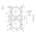
- FIG.4 is a plain view of main parts of a cylinder block from above as an example of a conventional crankcase for a diesel engine having two cylinders.
- a crankcase 1 comprises two cylinders in line installed upright adjacent to each other.
- a plurality of bolts for fastening each of the cylinders 7 to the cylinder head are provided on a cylinder wall arranged around each of the cylinders.
- the fastening bolts are shown as fastening bolt holes 3.
- head bolt reinforcing members 3a are provided around the cylinder hole and each of the reinforcing members protrudes around the cylinder hole by 45 degree from each other from the horizontal and vertical lines and the fastening bolt holes are bored to meet the reinforcing members.
- the crankcase 1 has a cylinder top panel 2 formed on the top thereof and reinforcing members such as head bolt reinforcing members 3a installed consecutively around the bolt holes 3.
- the reinforcing members such as the head bolt reinforcing members 3a supports the force acting on the crankcase by supporting the crankcase 1.
- the deformation of the cylinder top plate becomes more evident in response to the higher supercharging and higher output of the engine.
- the deformations often take place in a middle section of the fastening bolts 3, in a section between the fastening bolts in the horizontal line 20 connecting the centers of two adjacent cylinders, in particular, sections Z on the vertical lines from the centers of the cylinders and sections Y on the horizontal lines 20 perpendicular to the vertical lines.
- Patent Document 1 JP10-311242A proposes a two-part structure of a cylinder block to prevent the deformation of the crankcase in order to prevent the deformation of the crankcase
- Patent Document 2 JP2000-310157A proposes to improve reliability while coping with the high output of a diesel engine of in-line four cylinder type, by increasing the cooling performance in the vicinity of a cylinder axis center having a high load, and the rigidity of a cylinder head around a cylinder in particular, in the cylinder head by providing reinforcing ribs over an upper surface of the lower deck part of the cylinder head and also cross drill holes for leading cooling water into the reinforcing ribs.
- the object of Patent Document 1 is to solve the problems in the case of using the cylinder block of the two-part structure and Patent Document 2 relates to the cylinder head instead of the crankcase.
- the deformations of the cylinder top plate 2 are more evident in places far from the cylinder head fastening bolts 3, e.g. at the sections Z on the vertical lines from the centers of the cylinders and sections Y on the horizontal lines 20 perpendicular to the vertical lines.
- the deformation of the cylinder top plate 2 causes a droop of the top plate 2 toward inside of the hole of the cylinder 7.
- the deformation is small due to the number of bosses arranged around it and the reinforcing is easy.
- the middle sections Z between the fastening bolts 3 on the horizontal line 20 the middle sections Z are located on the vertical line of the cylinder center
- the number of the bosses is small and thus the deformation is more evident and it is difficult to reinforce the area.
- an object of the present invention is to provide a structure of a crankcase which is capable of coping with increased combustion pressure inside a cylinder of an engine having a plurality of cylinders (in-line cylinders) with a means for suppressing the deformation near a middle section (section Z) between fastening bolts in a direction parallel to a center-connecting line (horizontal line) connecting centers of the pair of the adjacent cylinders.
- the present invention proposes structure of a crankcase, which has a plurality of in-line cylinders installed upright in vicinity of each other, and a plurality of bolts arranged on an outer wall surrounding each of the cylinders for fastening the cylinders to a cylinder head, the structure comprising: a reinforcing rib formed on the outer wall at a middle section between the adjacent fastening bolts in a direction parallel to a direction of a center-connecting line connecting centers of the adjacent cylinders, the reinforcing rib extending downward continuously from the cylinder in the direction parallel to the center line of the cylinder.
- the reinforcing rib may have the structures shown below.
- the deformation of the cylinder top plate is substantially high at the middle section between fastening bolts in a direction parallel to a center-connecting line (horizontal line) connecting centers of the pair of the adjacent cylinders as there are only few bosses around the middle section.
- the reinforcing rib is formed on the outer wall of the cylinder at the middle section in the direction connecting centers of the adjacent cylinders and the reinforcing rib extends downward continuously from the bottom surface of the cylinder top plate in a direction parallel to the center line of the cylinder so as to improve the rigidity at the middle section and further prevents the droop of the top plate toward inside of the cylinder, thereby preventing the deformation of the cylinder top plate.
- crankcase of the engine which is capable of coping with increased combustion pressure inside the cylinder due to a high supercharging and a high output of an engine can be obtained by simply adding the reinforcing rib of a simple and inexpensive structure requiring only few extra processes, which can suppress the deformation at the middle section between the fastening bolts in the center-connecting line.
- the reinforcing rib is provided at each of the middle sections between the adjacent fastening bolts in the direction connecting centers of the adjacent cylinders where the rigidity of the outer wall is the smallest so as to improve the rigidity and average out the deformation of the cylinder top plate.
- the reinforcing rib is provided at each of the middle sections and the reinforcing rib has a semicircular cross-sectional shape in the same manner as bosses for the fastening bolts so as to improve the rigidity and simplify the molding thereof.
- the reinforcing rib connects to the vertical part of the crankcase at the connection section thereof arranged lower than a supporting boss of the crankcase for supporting the cylinder liner so as to suppress the falling-down deformation of the supporting boss toward inside of the cylinder when the cylinder liner is supported by the supporting boss.
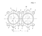
- FIG.1 is a plain view of main parts of a crankcase for a diesels engine relating to a preferred embodiment of the present invention.
- a crankcase 1 comprises two cylinders in line installed upright adjacent to each other. Further, a plurality of bolts for fastening each of the cylinders 7 to a cylinder head are provided on a cylinder wall arranged around each of the cylinders. Throughout the drawings, the fastening bolts are shown as fastening bolt holes 3.
- head bolt reinforcing members 3a are provided around the cylinder hole and each of the reinforcing members protrudes around the cylinder hole by 45 degree from each other from the horizontal and vertical lines and the fastening bolt holes are bored to meet the reinforcing members.
- a center of each cylinder 7 is indicated by a numeral 4, and a distance between the centers 4 is indicated by B. Further, a line connecting the centers 4 of the adjacent two cylinders is indicated by a numeral 20 (center-connecting line 20, hereinafter).
- the crankcase 1 has a cylinder top plate 2 formed on a top thereof.
- a pair of the fastening bolts 3 is provided on each side of the cylinder top plate 2 for each of the cylinders 7 with respect to the center-connecting line 20 connecting the centers of the cylinders.
- the number of the fastening bolts and the fastening bolt holes can be arbitrary.
- each of reinforcing ribs 6 is provided at a middle section between the pair of the fastening bolts (shown as bolt holes 3) of an outer wall of the cylinder (cylinder wall).
- the reinforcing rib 6 extends continuously from a bottom surface 2a (ref. FIG.2 ) of the cylinder top plate 2 (with a connection radius R) in a direction parallel to a center line of the cylinder and connects smoothly to a vertical part 8 of the crankcase 1 at a bottom portion thereof as shown in FIG.2 .
- FIG.3 illustrates a sectional view of the crankcase 1 having a cylinder liner 10 installed therein.
- a shoulder part 10a of the cylinder liner 10 is pushed downward between the cylinder head 11 and a supporting boss 5 of the crankcase 1 by a force F, and a water chamber 12 is formed outside of the shoulder part 10a.
- the water chamber 12 is in communication with the cylinder head 11 at an exit 14 thereof.
- a plurality of O-rings 13 for sealing is also shown in the drawing.
- the reinforcing rib 6 connects smoothly to the vertical part 8 of the crankcase at a connection section 2c thereof which is arranged lower than the supporting boss 5 of the crankcase for supporting the cylinder.
- the connection section 2c is supported by a high rigid portion of the supporting boss 5.
- connection section 2c is arranged lower than the supporting boss 5 so that the strength of the supporting boss 5 is reinforced by the reinforcing rib 6 in the vertical direction thereof and thus the falling down deformation of the supporting boss 5 to an inner side thereof when supporting the cylinder liner 10 is prevented.
- the reinforcing rib 6 is provided at each of the middle sections between the bolt holes 3 on the outer wall of the cylinder, where the rigidity is the smallest.
- the reinforcing rib 6 has a semicircular cross-sectional shape with radius r in the same manner as the boss for the fastening bolts 3 so as to enhance the strength thereof.
- the deformation of the cylinder top plate 2 is substantially high at the middle section which has only few bosses in the area and in the present embodiment, the reinforcing rib is formed on the outer wall of the cylinder at the middle section in the direction connecting centers of the adjacent cylinders and the reinforcing rib 6 extends downward continuously from the bottom surface 2a of the cylinder top plate 2 in a direction parallel to the center line 4a of the cylinder so as to improve the rigidity at the middle section and further prevents the droop of the top plate 2 toward inside of the cylinder 7, thereby preventing the deformation of the cylinder top plate.
- the deformation of the cylinder top plate 2 can be suppressed by simply adding the reinforcing rib 6 which is a inexpensive and simple means with a simple structure requiring a few extra processes.
- This can obtain a crankcase 1 capable of coping with increased combustion pressure inside a cylinder due to a high supercharging and a high output of an engine.
- a structure of a crankcase capable of coping with increased combustion pressure inside a cylinder due to a high supercharging and a high output of an engine can be obtained by using a means which can suppress the deformation at the middle section between the fastening bolts in the center-connecting line with a simple inexpensive means of a simple structure requiring only few extra processes.
Landscapes
- Engineering & Computer Science (AREA)
- Chemical & Material Sciences (AREA)
- Combustion & Propulsion (AREA)
- Mechanical Engineering (AREA)
- General Engineering & Computer Science (AREA)
- Cylinder Crankcases Of Internal Combustion Engines (AREA)
Abstract
An object of the present invention is to propose a structure of a crankcase capable of coping with increased combustion pressure inside a cylinder of an engine by a simple and inexpensive means for suppressing the deformation at a middle section between adjacent fastening bolts in a direction connecting the centers of adjacent cylinders. The structure of the crankcase which has a plurality of cylinders and a plurality of bolts arranged on both sides of each of the cylinders for fastening the cylinders to a cylinder head, the structure of the crankcase comprises a reinforcing rib 6 formed on an outer wall of the cylinder at a middle section between the adjacent fastening bolts 3 in a direction 20 connecting centers of the adjacent cylinders, the reinforcing rib extending downward continuously from the cylinder top plate in a direction parallel to a center line 4a of the cylinder.
Description
- The present invention relates to a structure of a crankcase which is applicable to a diesel engine and has a plurality of cylinders having plural bolts on both sides of each cylinder for fixing to a cylinder head.
- Many means have been tried to improve the strength of crankcase components of a diesel engine of recent years with higher supercharging and higher output.
FIG.4 is a plain view of main parts of a cylinder block from above as an example of a conventional crankcase for a diesel engine having two cylinders.
InFIG.4 , acrankcase 1 comprises two cylinders in line installed upright adjacent to each other. Further, a plurality of bolts for fastening each of the cylinders 7 to the cylinder head are provided on a cylinder wall arranged around each of the cylinders. Throughout the drawings, the fastening bolts are shown as fasteningbolt holes 3. InFIG.4 , headbolt reinforcing members 3a are provided around the cylinder hole and each of the reinforcing members protrudes around the cylinder hole by 45 degree from each other from the horizontal and vertical lines and the fastening bolt holes are bored to meet the reinforcing members. - The
crankcase 1 has acylinder top panel 2 formed on the top thereof and reinforcing members such as headbolt reinforcing members 3a installed consecutively around thebolt holes 3.
The reinforcing members such as the headbolt reinforcing members 3a supports the force acting on the crankcase by supporting thecrankcase 1. - In the
crankcase 1 of the engine, the deformation of the cylinder top plate becomes more evident in response to the higher supercharging and higher output of the engine. Particularly, the deformations often take place in a middle section of thefastening bolts 3, in a section between the fastening bolts in thehorizontal line 20 connecting the centers of two adjacent cylinders, in particular, sections Z on the vertical lines from the centers of the cylinders and sections Y on thehorizontal lines 20 perpendicular to the vertical lines. - To take measures against the deformations of the
crankcase 1 and the cylinder head, Patent Document 1 (JP10-311242A JP2000-310157A Patent Document 1 is to solve the problems in the case of using the cylinder block of the two-part structure andPatent Document 2 relates to the cylinder head instead of the crankcase. - Even with the methods disclosed in the documents, it still requires to increase the force to fasten the cylinder head bolts and also to modify the
cylinder top plate 2 of the engine to a large extent in order to cope with the increase in the combustion pressure inside the cylinder in response to the higher supercharging and higher output of the engine. - The deformations of the
cylinder top plate 2 are more evident in places far from the cylinder head fasteningbolts 3, e.g. at the sections Z on the vertical lines from the centers of the cylinders and sections Y on thehorizontal lines 20 perpendicular to the vertical lines.
The deformation of thecylinder top plate 2 causes a droop of thetop plate 2 toward inside of the hole of the cylinder 7. At the sections Y which intersect thehorizontal lines 20 connecting the centers of the adjacent cylinders, the deformation is small due to the number of bosses arranged around it and the reinforcing is easy.
However, at the middle sections Z between thefastening bolts 3 on the horizontal line 20 (the middle sections Z are located on the vertical line of the cylinder center), the number of the bosses is small and thus the deformation is more evident and it is difficult to reinforce the area. -
- [PATENT DOCUMENT 1]
JP10-311242A - [PATENT DOCUMENT 2]
JP2000-310157A - In view of the above issues, an object of the present invention is to provide a structure of a crankcase which is capable of coping with increased combustion pressure inside a cylinder of an engine having a plurality of cylinders (in-line cylinders) with a means for suppressing the deformation near a middle section (section Z) between fastening bolts in a direction parallel to a center-connecting line (horizontal line) connecting centers of the pair of the adjacent cylinders.
- To achieve the object of the present invention, the present invention proposes structure of a crankcase, which has a plurality of in-line cylinders installed upright in vicinity of each other, and a plurality of bolts arranged on an outer wall surrounding each of the cylinders for fastening the cylinders to a cylinder head, the structure comprising: a reinforcing rib formed on the outer wall at a middle section between the adjacent fastening bolts in a direction parallel to a direction of a center-connecting line connecting centers of the adjacent cylinders, the reinforcing rib extending downward continuously from the cylinder in the direction parallel to the center line of the cylinder.
- The reinforcing rib may have the structures shown below.
- (1) The reinforcing rib is provided at each of the middle sections between the adjacent fastening bolts in a direction connecting centers of the adjacent cylinders.
- (2) The reinforcing rib is provided at each of the middle sections and the reinforcing rib has a semicircular cross-sectional shape in the same manner as bosses for the fastening bolts.
- (3) The reinforcing rib connects to a vertical part of the crankcase at a connection section thereof which is arranged lower than a supporting boss of the crankcase for supporting a cylinder liner.
- According to the present invention, in the structure of the crankcase, the deformation of the cylinder top plate is substantially high at the middle section between fastening bolts in a direction parallel to a center-connecting line (horizontal line) connecting centers of the pair of the adjacent cylinders as there are only few bosses around the middle section. In the present invention, the reinforcing rib is formed on the outer wall of the cylinder at the middle section in the direction connecting centers of the adjacent cylinders and the reinforcing rib extends downward continuously from the bottom surface of the cylinder top plate in a direction parallel to the center line of the cylinder so as to improve the rigidity at the middle section and further prevents the droop of the top plate toward inside of the cylinder, thereby preventing the deformation of the cylinder top plate.
- Therefore, the crankcase of the engine, which is capable of coping with increased combustion pressure inside the cylinder due to a high supercharging and a high output of an engine can be obtained by simply adding the reinforcing rib of a simple and inexpensive structure requiring only few extra processes, which can suppress the deformation at the middle section between the fastening bolts in the center-connecting line.
- Further, the reinforcing rib is provided at each of the middle sections between the adjacent fastening bolts in the direction connecting centers of the adjacent cylinders where the rigidity of the outer wall is the smallest so as to improve the rigidity and average out the deformation of the cylinder top plate.
- Furthermore, the reinforcing rib is provided at each of the middle sections and the reinforcing rib has a semicircular cross-sectional shape in the same manner as bosses for the fastening bolts so as to improve the rigidity and simplify the molding thereof.
- Moreover, the reinforcing rib connects to the vertical part of the crankcase at the connection section thereof arranged lower than a supporting boss of the crankcase for supporting the cylinder liner so as to suppress the falling-down deformation of the supporting boss toward inside of the cylinder when the cylinder liner is supported by the supporting boss.
-
- [
FIG.1 ] A plain view of main parts of a crankcase for a diesels engine relating to a preferred embodiment of the present invention. - [
FIG.2 ] A sectional view in relation to the preferred embodiment taken along a line A-A ofFIG.1 - [
FIG.3 ] A sectional view of the crankcase having a cylinder liner installed therein in relation to the preferred embodiment of the present invention. - [
FIG.4 ] A plain view of main parts of a conventional crankcase corresponding toFIG.1 . - A preferred embodiment of the present invention will now be described in detail with reference to the accompanying drawings. It is intended, however, that unless particularly specified, dimensions, materials, shape, its relative positions and the like shall be interpreted as illustrative only and not limitative of the scope of the present.
-
FIG.1 is a plain view of main parts of a crankcase for a diesels engine relating to a preferred embodiment of the present invention.
InFIG.1 , acrankcase 1 comprises two cylinders in line installed upright adjacent to each other. Further, a plurality of bolts for fastening each of the cylinders 7 to a cylinder head are provided on a cylinder wall arranged around each of the cylinders. Throughout the drawings, the fastening bolts are shown as fasteningbolt holes 3. InFIG.1 , headbolt reinforcing members 3a are provided around the cylinder hole and each of the reinforcing members protrudes around the cylinder hole by 45 degree from each other from the horizontal and vertical lines and the fastening bolt holes are bored to meet the reinforcing members.
A center of each cylinder 7 is indicated by anumeral 4, and a distance between thecenters 4 is indicated by B. Further, a line connecting thecenters 4 of the adjacent two cylinders is indicated by a numeral 20 (center-connectingline 20, hereinafter). - The
crankcase 1 has acylinder top plate 2 formed on a top thereof. On thecylinder top plate 2, a pair of thefastening bolts 3 is provided on each side of thecylinder top plate 2 for each of the cylinders 7 with respect to the center-connectingline 20 connecting the centers of the cylinders. However, the number of the fastening bolts and the fastening bolt holes can be arbitrary. - As shown in
FIG.2 , each of reinforcingribs 6 is provided at a middle section between the pair of the fastening bolts (shown as bolt holes 3) of an outer wall of the cylinder (cylinder wall).
The reinforcingrib 6 extends continuously from abottom surface 2a (ref.FIG.2 ) of the cylinder top plate 2 (with a connection radius R) in a direction parallel to a center line of the cylinder and connects smoothly to a vertical part 8 of thecrankcase 1 at a bottom portion thereof as shown inFIG.2 .
Further,FIG.3 illustrates a sectional view of thecrankcase 1 having acylinder liner 10 installed therein.
InFIG.3 , ashoulder part 10a of thecylinder liner 10 is pushed downward between thecylinder head 11 and a supportingboss 5 of thecrankcase 1 by a force F, and awater chamber 12 is formed outside of theshoulder part 10a. Thewater chamber 12 is in communication with thecylinder head 11 at anexit 14 thereof. A plurality of O-rings 13 for sealing is also shown in the drawing.
In the present invention, thereinforcing rib 6 connects smoothly to the vertical part 8 of the crankcase at aconnection section 2c thereof which is arranged lower than the supportingboss 5 of the crankcase for supporting the cylinder. Theconnection section 2c is supported by a high rigid portion of the supportingboss 5.
Theconnection section 2c is arranged lower than the supportingboss 5 so that the strength of the supportingboss 5 is reinforced by the reinforcingrib 6 in the vertical direction thereof and thus the falling down deformation of the supportingboss 5 to an inner side thereof when supporting thecylinder liner 10 is prevented. - In this manner, in the preferred embodiment, the reinforcing
rib 6 is provided at each of the middle sections between the bolt holes 3 on the outer wall of the cylinder, where the rigidity is the smallest.
By providing the reinforcingrib 6 at the middle section where the rigidity of the outer wall is the smallest, the rigidity of the part is improved and the deformation of the cylinder top plate is averaged out.
Moreover, the reinforcingrib 6 has a semicircular cross-sectional shape with radius r in the same manner as the boss for thefastening bolts 3 so as to enhance the strength thereof. - As described above, the deformation of the cylinder
top plate 2 is substantially high at the middle section which has only few bosses in the area and in the present embodiment, the reinforcing rib is formed on the outer wall of the cylinder at the middle section in the direction connecting centers of the adjacent cylinders and the reinforcingrib 6 extends downward continuously from thebottom surface 2a of the cylindertop plate 2 in a direction parallel to thecenter line 4a of the cylinder so as to improve the rigidity at the middle section and further prevents the droop of thetop plate 2 toward inside of the cylinder 7, thereby preventing the deformation of the cylinder top plate. - Accordingly, the deformation of the cylinder
top plate 2 can be suppressed by simply adding the reinforcingrib 6 which is a inexpensive and simple means with a simple structure requiring a few extra processes. This can obtain acrankcase 1 capable of coping with increased combustion pressure inside a cylinder due to a high supercharging and a high output of an engine. - According to the present invention, a structure of a crankcase capable of coping with increased combustion pressure inside a cylinder due to a high supercharging and a high output of an engine can be obtained by using a means which can suppress the deformation at the middle section between the fastening bolts in the center-connecting line with a simple inexpensive means of a simple structure requiring only few extra processes.
Claims (7)
- A structure of a crankcase which has a plurality of cylinders and a plurality of bolts arranged on both sides of each of the cylinders for fastening the cylinders to a cylinder head, the structure of the crankcase comprising:a reinforcing rib formed on an outer wall of the cylinder at a middle section between the adjacent fastening bolts in a direction connecting centers of the adjacent cylinders, the reinforcing rib extending downward continuously from the cylinder top plate in a direction parallel to a center line of the cylinder.
- The structure of the crankcase according to claim 1, wherein the reinforcing rib is provided at each of the middle sections.
- The structure of the crankcase according to claim 2,
wherein the reinforcing rib has a semicircular cross-sectional shape in the same manner as bosses for the fastening bolts. - The structure of the crankcase according to claim 1,
wherein the reinforcing rib connects to a vertical part of the crankcase at a connection section thereof which is arranged lower than a supporting boss of the crankcase for supporting a cylinder liner. - The structure of the crankcase according to claim 1, which has a plurality of in-line cylinders installed upright in vicinity of each other, and a plurality of bolts arranged on an outer wall surrounding each of the cylinders for fastening the cylinders to a cylinder head, the structure comprising:the reinforcing rib formed on the outer wall at a middle section between the adjacent fastening bolts in a direction parallel to a direction of a center-connecting line connecting centers of the adjacent cylinders, the reinforcing rib extending downward continuously from the cylinder in the direction parallel to the center line of the cylinder.
- The structure of the crankcase according to claim 5,
wherein the reinforcing rib is provided at each of the middle sections. - The structure of the crankcase according to claim 5,
wherein the reinforcing rib is provided at each of the middle sections and the reinforcing rib has a semicircular cross-sectional shape in the same manner as bosses for the fastening bolts.
Applications Claiming Priority (2)
| Application Number | Priority Date | Filing Date | Title |
|---|---|---|---|
| JP2008315394A JP2010138779A (en) | 2008-12-11 | 2008-12-11 | Structure of crankcase |
| PCT/JP2009/066266 WO2010067652A1 (en) | 2008-12-11 | 2009-09-17 | Structure for crankcase |
Publications (1)
| Publication Number | Publication Date |
|---|---|
| EP2290216A1 true EP2290216A1 (en) | 2011-03-02 |
Family
ID=42242645
Family Applications (1)
| Application Number | Title | Priority Date | Filing Date |
|---|---|---|---|
| EP09831758A Withdrawn EP2290216A1 (en) | 2008-12-11 | 2009-09-17 | Structure for crankcase |
Country Status (4)
| Country | Link |
|---|---|
| US (1) | US20110056454A1 (en) |
| EP (1) | EP2290216A1 (en) |
| JP (1) | JP2010138779A (en) |
| WO (1) | WO2010067652A1 (en) |
Cited By (1)
| Publication number | Priority date | Publication date | Assignee | Title |
|---|---|---|---|---|
| WO2020131625A1 (en) * | 2018-12-19 | 2020-06-25 | Cummins Inc. | Unique block rib geometry for reducing liner distortion |
Family Cites Families (8)
| Publication number | Priority date | Publication date | Assignee | Title |
|---|---|---|---|---|
| JPH0586962A (en) * | 1991-09-30 | 1993-04-06 | Toyota Motor Corp | Cylinder block |
| JPH10311242A (en) | 1997-05-12 | 1998-11-24 | Yanmar Diesel Engine Co Ltd | Cylinder block of multicylinder internal combustion engine |
| US6116198A (en) * | 1997-07-21 | 2000-09-12 | Cummins Engine Company, Inc. | Replaceable cylinder liner with improved cooling |
| JP2000310157A (en) | 1999-04-27 | 2000-11-07 | Mazda Motor Corp | Cylinder head structure of multi-cylinder engine |
| JP4306461B2 (en) * | 2004-01-14 | 2009-08-05 | トヨタ自動車株式会社 | Cylinder block fastening structure and engine body provided with the same |
| US8047607B1 (en) * | 2004-06-08 | 2011-11-01 | Behshad Shokouhi | Modular stackable furniture systems |
| US8033612B2 (en) * | 2008-12-24 | 2011-10-11 | Mity-Lite, Inc. | Comfortable mesh folding chair |
| USD651013S1 (en) * | 2010-01-20 | 2011-12-27 | Charles Swanson | Metal chair with wood seat |
-
2008
- 2008-12-11 JP JP2008315394A patent/JP2010138779A/en not_active Withdrawn
-
2009
- 2009-09-17 US US12/989,502 patent/US20110056454A1/en not_active Abandoned
- 2009-09-17 EP EP09831758A patent/EP2290216A1/en not_active Withdrawn
- 2009-09-17 WO PCT/JP2009/066266 patent/WO2010067652A1/en not_active Ceased
Non-Patent Citations (1)
| Title |
|---|
| See references of WO2010067652A1 * |
Cited By (3)
| Publication number | Priority date | Publication date | Assignee | Title |
|---|---|---|---|---|
| WO2020131625A1 (en) * | 2018-12-19 | 2020-06-25 | Cummins Inc. | Unique block rib geometry for reducing liner distortion |
| US11536222B2 (en) | 2018-12-19 | 2022-12-27 | Cummins Inc. | Block ribs for reducing liner distortion |
| US11698042B2 (en) | 2018-12-19 | 2023-07-11 | Cummins Inc. | Unique block rib geometry for reducing liner distortion |
Also Published As
| Publication number | Publication date |
|---|---|
| WO2010067652A1 (en) | 2010-06-17 |
| US20110056454A1 (en) | 2011-03-10 |
| JP2010138779A (en) | 2010-06-24 |
Similar Documents
| Publication | Publication Date | Title |
|---|---|---|
| KR102068372B1 (en) | Engine piston | |
| US8256389B2 (en) | Cylinder block | |
| US7322320B2 (en) | Engine cylinder block | |
| US8176890B2 (en) | Engine oil pan structure | |
| US11248558B2 (en) | Engine | |
| US7389763B2 (en) | Cylinder block integrated with crankcase | |
| US8683913B2 (en) | Piston for an internal combustion engine | |
| EP2290216A1 (en) | Structure for crankcase | |
| KR20130127546A (en) | Cylinder head of internal combustion engine | |
| JP4591482B2 (en) | Internal combustion engine | |
| JP2008248842A (en) | Piston of internal combustion engine | |
| US7077095B2 (en) | Cylinder block structure | |
| JP5665498B2 (en) | Crosshead of crosshead type diesel engine | |
| JP2012102630A (en) | Crosshead of crosshead diesel engine | |
| KR100551516B1 (en) | Small sweeper and cylinder frame | |
| JP2011089429A (en) | Engine frame and method for manufacturing the same | |
| KR101283081B1 (en) | Cylinder block combined with cylinder liner | |
| KR100828795B1 (en) | Middle deck rigid reinforcement structure of cylinder head | |
| JP2005113887A (en) | Cooling channel structure of internal combustion engine | |
| KR100802934B1 (en) | Reinforcement structure of cylinder block | |
| JP2606040B2 (en) | Engine cylinder body | |
| JPS6218678Y2 (en) | ||
| JPH0861139A (en) | Cylinder block for internal combustion engine | |
| JP2006161639A (en) | Rudder frame structure | |
| JP4780086B2 (en) | Oil level sensor mounting structure |
Legal Events
| Date | Code | Title | Description |
|---|---|---|---|
| PUAI | Public reference made under article 153(3) epc to a published international application that has entered the european phase |
Free format text: ORIGINAL CODE: 0009012 |
|
| 17P | Request for examination filed |
Effective date: 20101027 |
|
| AK | Designated contracting states |
Kind code of ref document: A1 Designated state(s): AT BE BG CH CY CZ DE DK EE ES FI FR GB GR HR HU IE IS IT LI LT LU LV MC MK MT NL NO PL PT RO SE SI SK SM TR |
|
| AX | Request for extension of the european patent |
Extension state: AL BA RS |
|
| DAX | Request for extension of the european patent (deleted) | ||
| STAA | Information on the status of an ep patent application or granted ep patent |
Free format text: STATUS: THE APPLICATION HAS BEEN WITHDRAWN |
|
| 18W | Application withdrawn |
Effective date: 20140812 |