EP2290198A2 - Bearing spacer and housing - Google Patents
Bearing spacer and housing Download PDFInfo
- Publication number
- EP2290198A2 EP2290198A2 EP10172023A EP10172023A EP2290198A2 EP 2290198 A2 EP2290198 A2 EP 2290198A2 EP 10172023 A EP10172023 A EP 10172023A EP 10172023 A EP10172023 A EP 10172023A EP 2290198 A2 EP2290198 A2 EP 2290198A2
- Authority
- EP
- European Patent Office
- Prior art keywords
- bore
- outer race
- keyways
- bearing
- center housing
- Prior art date
- Legal status (The legal status is an assumption and is not a legal conclusion. Google has not performed a legal analysis and makes no representation as to the accuracy of the status listed.)
- Granted
Links
- 125000006850 spacer group Chemical group 0.000 title 1
- 238000000034 method Methods 0.000 claims abstract description 14
- 239000000314 lubricant Substances 0.000 claims description 35
- 230000007246 mechanism Effects 0.000 description 26
- 238000002485 combustion reaction Methods 0.000 description 7
- 238000005096 rolling process Methods 0.000 description 6
- 238000005516 engineering process Methods 0.000 description 2
- 238000003754 machining Methods 0.000 description 2
- 230000009286 beneficial effect Effects 0.000 description 1
- 239000000567 combustion gas Substances 0.000 description 1
- 238000013461 design Methods 0.000 description 1
- 230000001627 detrimental effect Effects 0.000 description 1
- 238000010586 diagram Methods 0.000 description 1
- 239000000446 fuel Substances 0.000 description 1
- 230000005484 gravity Effects 0.000 description 1
- 238000003780 insertion Methods 0.000 description 1
- 230000037431 insertion Effects 0.000 description 1
- 238000012986 modification Methods 0.000 description 1
- 230000004048 modification Effects 0.000 description 1
- 230000037361 pathway Effects 0.000 description 1
- 230000008707 rearrangement Effects 0.000 description 1
- 238000006467 substitution reaction Methods 0.000 description 1
- 238000012546 transfer Methods 0.000 description 1
Images


Classifications
-
- F—MECHANICAL ENGINEERING; LIGHTING; HEATING; WEAPONS; BLASTING
- F01—MACHINES OR ENGINES IN GENERAL; ENGINE PLANTS IN GENERAL; STEAM ENGINES
- F01D—NON-POSITIVE DISPLACEMENT MACHINES OR ENGINES, e.g. STEAM TURBINES
- F01D25/00—Component parts, details, or accessories, not provided for in, or of interest apart from, other groups
- F01D25/16—Arrangement of bearings; Supporting or mounting bearings in casings
- F01D25/162—Bearing supports
-
- F—MECHANICAL ENGINEERING; LIGHTING; HEATING; WEAPONS; BLASTING
- F02—COMBUSTION ENGINES; HOT-GAS OR COMBUSTION-PRODUCT ENGINE PLANTS
- F02C—GAS-TURBINE PLANTS; AIR INTAKES FOR JET-PROPULSION PLANTS; CONTROLLING FUEL SUPPLY IN AIR-BREATHING JET-PROPULSION PLANTS
- F02C6/00—Plural gas-turbine plants; Combinations of gas-turbine plants with other apparatus; Adaptations of gas- turbine plants for special use
- F02C6/04—Gas-turbine plants providing heated or pressurised working fluid for other apparatus, e.g. without mechanical power output
- F02C6/10—Gas-turbine plants providing heated or pressurised working fluid for other apparatus, e.g. without mechanical power output supplying working fluid to a user, e.g. a chemical process, which returns working fluid to a turbine of the plant
- F02C6/12—Turbochargers, i.e. plants for augmenting mechanical power output of internal-combustion piston engines by increase of charge pressure
-
- F—MECHANICAL ENGINEERING; LIGHTING; HEATING; WEAPONS; BLASTING
- F16—ENGINEERING ELEMENTS AND UNITS; GENERAL MEASURES FOR PRODUCING AND MAINTAINING EFFECTIVE FUNCTIONING OF MACHINES OR INSTALLATIONS; THERMAL INSULATION IN GENERAL
- F16C—SHAFTS; FLEXIBLE SHAFTS; ELEMENTS OR CRANKSHAFT MECHANISMS; ROTARY BODIES OTHER THAN GEARING ELEMENTS; BEARINGS
- F16C27/00—Elastic or yielding bearings or bearing supports, for exclusively rotary movement
- F16C27/04—Ball or roller bearings, e.g. with resilient rolling bodies
- F16C27/045—Ball or roller bearings, e.g. with resilient rolling bodies with a fluid film, e.g. squeeze film damping
-
- F—MECHANICAL ENGINEERING; LIGHTING; HEATING; WEAPONS; BLASTING
- F16—ENGINEERING ELEMENTS AND UNITS; GENERAL MEASURES FOR PRODUCING AND MAINTAINING EFFECTIVE FUNCTIONING OF MACHINES OR INSTALLATIONS; THERMAL INSULATION IN GENERAL
- F16C—SHAFTS; FLEXIBLE SHAFTS; ELEMENTS OR CRANKSHAFT MECHANISMS; ROTARY BODIES OTHER THAN GEARING ELEMENTS; BEARINGS
- F16C35/00—Rigid support of bearing units; Housings, e.g. caps, covers
- F16C35/04—Rigid support of bearing units; Housings, e.g. caps, covers in the case of ball or roller bearings
- F16C35/042—Housings for rolling element bearings for rotary movement
-
- F—MECHANICAL ENGINEERING; LIGHTING; HEATING; WEAPONS; BLASTING
- F05—INDEXING SCHEMES RELATING TO ENGINES OR PUMPS IN VARIOUS SUBCLASSES OF CLASSES F01-F04
- F05D—INDEXING SCHEME FOR ASPECTS RELATING TO NON-POSITIVE-DISPLACEMENT MACHINES OR ENGINES, GAS-TURBINES OR JET-PROPULSION PLANTS
- F05D2220/00—Application
- F05D2220/40—Application in turbochargers
-
- F—MECHANICAL ENGINEERING; LIGHTING; HEATING; WEAPONS; BLASTING
- F16—ENGINEERING ELEMENTS AND UNITS; GENERAL MEASURES FOR PRODUCING AND MAINTAINING EFFECTIVE FUNCTIONING OF MACHINES OR INSTALLATIONS; THERMAL INSULATION IN GENERAL
- F16C—SHAFTS; FLEXIBLE SHAFTS; ELEMENTS OR CRANKSHAFT MECHANISMS; ROTARY BODIES OTHER THAN GEARING ELEMENTS; BEARINGS
- F16C19/00—Bearings with rolling contact, for exclusively rotary movement
- F16C19/02—Bearings with rolling contact, for exclusively rotary movement with bearing balls essentially of the same size in one or more circular rows
- F16C19/14—Bearings with rolling contact, for exclusively rotary movement with bearing balls essentially of the same size in one or more circular rows for both radial and axial load
- F16C19/18—Bearings with rolling contact, for exclusively rotary movement with bearing balls essentially of the same size in one or more circular rows for both radial and axial load with two or more rows of balls
- F16C19/181—Bearings with rolling contact, for exclusively rotary movement with bearing balls essentially of the same size in one or more circular rows for both radial and axial load with two or more rows of balls with angular contact
- F16C19/183—Bearings with rolling contact, for exclusively rotary movement with bearing balls essentially of the same size in one or more circular rows for both radial and axial load with two or more rows of balls with angular contact with two rows at opposite angles
- F16C19/184—Bearings with rolling contact, for exclusively rotary movement with bearing balls essentially of the same size in one or more circular rows for both radial and axial load with two or more rows of balls with angular contact with two rows at opposite angles in O-arrangement
-
- F—MECHANICAL ENGINEERING; LIGHTING; HEATING; WEAPONS; BLASTING
- F16—ENGINEERING ELEMENTS AND UNITS; GENERAL MEASURES FOR PRODUCING AND MAINTAINING EFFECTIVE FUNCTIONING OF MACHINES OR INSTALLATIONS; THERMAL INSULATION IN GENERAL
- F16C—SHAFTS; FLEXIBLE SHAFTS; ELEMENTS OR CRANKSHAFT MECHANISMS; ROTARY BODIES OTHER THAN GEARING ELEMENTS; BEARINGS
- F16C2226/00—Joining parts; Fastening; Assembling or mounting parts
- F16C2226/50—Positive connections
-
- F—MECHANICAL ENGINEERING; LIGHTING; HEATING; WEAPONS; BLASTING
- F16—ENGINEERING ELEMENTS AND UNITS; GENERAL MEASURES FOR PRODUCING AND MAINTAINING EFFECTIVE FUNCTIONING OF MACHINES OR INSTALLATIONS; THERMAL INSULATION IN GENERAL
- F16C—SHAFTS; FLEXIBLE SHAFTS; ELEMENTS OR CRANKSHAFT MECHANISMS; ROTARY BODIES OTHER THAN GEARING ELEMENTS; BEARINGS
- F16C2360/00—Engines or pumps
- F16C2360/23—Gas turbine engines
- F16C2360/24—Turbochargers
-
- F—MECHANICAL ENGINEERING; LIGHTING; HEATING; WEAPONS; BLASTING
- F16—ENGINEERING ELEMENTS AND UNITS; GENERAL MEASURES FOR PRODUCING AND MAINTAINING EFFECTIVE FUNCTIONING OF MACHINES OR INSTALLATIONS; THERMAL INSULATION IN GENERAL
- F16C—SHAFTS; FLEXIBLE SHAFTS; ELEMENTS OR CRANKSHAFT MECHANISMS; ROTARY BODIES OTHER THAN GEARING ELEMENTS; BEARINGS
- F16C35/00—Rigid support of bearing units; Housings, e.g. caps, covers
- F16C35/04—Rigid support of bearing units; Housings, e.g. caps, covers in the case of ball or roller bearings
- F16C35/06—Mounting or dismounting of ball or roller bearings; Fixing them onto shaft or in housing
- F16C35/067—Fixing them in a housing
Definitions
- Subject matter disclosed herein relates generally to turbomachinery for internal combustion engines and, in particular, to techniques for locating a bearing assembly in a bore of a turbocharger.
- a conventional turbocharger typically relies on a center housing rotating assembly (CHRA) that includes a turbine wheel and a compressor wheel attached to a shaft rotatably supported by a bearing assembly located in a bore of a center housing.
- CHRA center housing rotating assembly
- a typical bearing assembly or bearing cartridge includes an outer race and an inner race, configured to receive a shaft, where the outer race and the inner race are separated by rolling elements such as ball bearings.
- a so-called "locating mechanism” restricts movement of a bearing assembly in the bore of the center housing.
- Various conventional locating mechanisms rely on radial insertion of a locating pin in an opening of an outer race of a bearing assembly. Such a mechanism restricts radial and/or axial movement of the bearing assembly and rotation of the outer race yet allows the inner race to spin freely. Additionally, such a mechanism allows for some radial movement of a bearing assembly, usually within defined clearances that fill with lubricant during operation to form a "squeeze film” that acts to damp vibration and noise.
- the degrees of radial and axial freedom may be chosen to be of particular magnitude or magnitudes depending on various goals.
- locating mechanisms that rely on a radial locating pin to locate a bearing assembly. For example, during operation of a turbocharger, significant axial loads can be generated that thrust the turbocharger shaft and associated components toward the compressor end or toward the turbine end of the turbocharger CHRA, which, in turn, can be transferred from the bearing assembly to the radial locating pin. Such forces make pin strength an important design factor.
- Another issue pertains to axial stack-up of components (e.g., how well do the components of a CHRA stack and how does this stacking affect operation and wear).
- a locating mechanism that relies on a radial locating pin does not provide advantages with respect to axial stacking; indeed, the nature of the pin and the outer race opening introduce geometric and operation concerns that can be disadvantageous.
- a locating mechanism such as the aforementioned radial pin locating mechanism, can be described in terms of "key/keyway pairs" that involve male (key) and female (keyway) components that act to locate an outer race of a bearing assembly.
- frictional contact between key and keyway components should remain low (1) to allow a bearing assembly to move freely in the radial plane (i.e., within its squeeze film) and (2) to limit wear between the keyway components.
- various exemplary locating mechanisms can reduce or alleviate issues associated with locating mechanisms that rely on radial pins. For example, by reducing friction, such exemplary mechanisms can reduce powerloss and thereby improve efficiency and performance of turbocharged internal combustion engines.
- Fig. 1 is a diagram of a turbocharger and an internal combustion engine.
- Fig. 2 is a cutaway perspective view of an exemplary turbocharger, along a plane defined by a line labeled A-A, which includes an anti-rotation mechanism for an outer race of a bearing assembly.
- Fig. 3 is an end view of the turbocharger of Fig. 2 along a plane defined by a line labeled B-B, which includes the anti-rotation mechanism; Fig. 3 also shows an example of a variation of the anti-rotation mechanism.
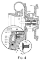
- Fig. 4 is a cross-sectional view of the turbocharger of Fig. 2 , along the plane defined by the line A-A, and an enlarged cross-sectional view, along a plane defined by a line labeled C-C in Fig. 2 , which includes the anti-rotation mechanism.
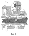
- Fig. 5 is a cross-sectional view of a turbocharger and a cross-sectional view of a plate with integral key components of an anti-rotation mechanism, along a plane defined by a line labeled D-D.
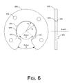
- Fig. 6 is a plan view and a side view of the plate of Fig. 5 .
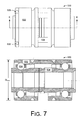
- Fig. 7 is a plan view and a cross-sectional view of a bearing assembly of the turbocharger of Fig. 5 , along a plane defined by a line labeled E-E in Fig. 7 .
- Fig. 8 is a plan view and a side view of the plate of Fig. 6 and the bearing assembly of Fig. 7 .
- Fig. 9 is a plan view and a side view of a plate and the bearing assembly where the plate includes a keyway and the bearing assembly includes a key.
- a conventional system 100 includes an internal combustion engine 110 and a turbocharger 120.
- the internal combustion engine 110 includes an engine block 118 housing one or more combustion chambers that operatively drive a shaft 112.
- an intake port 114 provides a flow path for air to the engine block 118 while an exhaust port 116 provides a flow path for exhaust from the engine block 118.
- the turbocharger 120 acts to extract energy from the exhaust and to provide energy to intake air, which may be combined with fuel to form combustion gas.
- the turbocharger 120 includes an air inlet 134, a shaft 122, a compressor 124, a turbine 126, a housing 128 and an exhaust outlet 136.
- the housing 128 may be referred to as a center housing as it is disposed between the compressor 124 and the turbine 126.
- the shaft 122 may be a shaft assembly that includes a variety of components.
- variable geometry unit and variable geometry controller optionally includes a variable geometry unit and a variable geometry controller.
- the variable geometry unit and variable geometry controller optionally include features such as those associated with commercially available variable geometry turbochargers (VGTs).
- VGTs include, for example, the GARRETT® VNT TM and AVNT TM turbochargers, which use multiple adjustable vanes to control the flow of exhaust across a turbine.
- An exemplary turbocharger may employ wastegate technology as an alternative or in addition to variable geometry technology.
- Fig. 2 shows a cross-sectional perspective view of an exemplary turbocharger 200 where a plane defined by a line A-A, a plane defined by a line B-B and a plane defined by a line C-C are shown.
- the A-A plane is the cross-sectional plane of the view of Fig. 2 whereas a view for the B-B plane is shown in Fig. 3 and a view for the C-C is shown in Fig. 4 .
- the turbocharger 200 serves as a non-limiting example to describe various exemplary devices, methods, systems, etc., disclosed herein.
- the turbocharger 200 includes a center housing 210, a shaft 220, a bearing assembly 230, a compressor section 240, a turbine section 260 and a locating mechanism that includes a plate 270 and an anti-rotation component 280.
- the compressor section 240 includes a compressor housing 241 that houses a compressor wheel 242 that includes a hub 243 and blades 244.
- the turbine section 260 includes a turbine housing 261 that houses a turbine wheel 262 that includes a hub 263 and blades 264. As shown, the compressor wheel 242 and the turbine wheel 262 are operably connected to the shaft 220.
- the shaft 220 may be made of multiple components that form a single operable shaft unit.
- the compressor wheel 240, the turbine wheel 260 and the shaft 220 have an axis of rotation substantially coincident with the z-axis.
- the center housing 210 includes a bore 215 that is configured to receive a bearing assembly 230, which, in turn, receives the shaft 220 and allows for rotation of the shaft 220 about the z-axis.
- the center housing 210 includes lubricant pathways to allow lubricant to flow to and from the bearing assembly 230.
- the housing 210 includes a lubricant inlet 212 and a lubricant outlet 216. Intermediate the lubricant inlet 212 and the lubricant outlet 216 are various features that define one or more lubricant flow paths.
- An axial lubricant path 213 is configured to direct lubricant from the lubricant inlet 212 to openings along the bore 215 of the center housing 210.
- lubricant can flow within the center housing 210 (e.g., enter the bearing assembly 230) and ultimately drain from the housing via the lubricant outlet 216 (e.g., due to gravity).
- a stop 211 of the center housing 210 positioned at a turbine end of the bore 215; (2) the plate 270 attached to the center housing 210, positioned at a compressor end of the bore 213; (iii) a recess in the center housing 210 (see Figs. 3 and 4 ); and (iv) the anti-rotation component 280, which may be positioned at any of a variety of locations along the length of an outer race of a bearing assembly.
- a stop 211 of the center housing 210 positioned at a turbine end of the bore 215
- the plate 270 attached to the center housing 210 positioned at a compressor end of the bore 213
- a recess in the center housing 210 see Figs. 3 and 4
- the anti-rotation component 280 which may be positioned at any of a variety of locations along the length of an outer race of a bearing assembly.
- the anti-rotation component 280 is shown as being positioned at the compressor end of the bore 215 and adjacent a compressor end of the bearing assembly 230 where at least a portion of the anti-rotation component 280 is seated in a recess of the center housing 210.
- Fig. 3 shows a view of the turbocharger 200 from the B-B plane. Specifically, Fig. 3 shows the center housing 210, a recess 217 in the center housing 210, the shaft 220, the bearing assembly 230 and the anti-rotation component 280.
- the bearing assembly 230 includes an outer race 232, an inner race 234 and rolling elements 236.
- the axial lubricant path 213 and the bore 215 are shown along with four apertures to receive bolts or the like to attach the plate 270 to the center housing 210.
- the outer race 232 includes a notched or keyway portion 233 that cooperates with a key portion of the anti-rotation component 280.
- the center housing 210 has a beveled edge at the compressor end of the bore 215 and the recess 217 is positioned adjacent the bore 215.
- the anti-rotation component 280 is seated in the recess 217, which is configured to limit rotation of the anti-rotation component 280.
- the recess 217 and the anti-rotation component both have an oblong shape where that of the recess 217 is slightly larger in widthwise dimension than a corresponding dimension of the anti-rotation component 280, which while allowing for some movement, restricts excessive movement of the anti-rotation component 280 in the recess 217.
- the anti-rotation component 280 has an outer radius R C and a width W C while the recess 217 has an outer radius R R and a width W R . As shown, these 2D dimensions of the recess 217 exceed those of the anti-rotation component 280. While Fig. 3 shows a particular configuration and shape, as described herein, other configurations and shapes may be used (see, e.g., the example 290). The example of Fig. 3 also shows an offset between an axis of rotation of the shaft 220 and an axis of rotation of the anti-rotation component 280.
- the anti-rotation component 280 limits rotation of the outer race 232 about the axis of rotation of the shaft 220.
- the amount of rotation of the outer race 232 may be determined wholly or in part by one or more factors such as dimensions of the recess 217, dimensions of the anti-rotation component 280, dimensions of the keyway 233, etc.
- a point or points of contact exist between the keyway 233 and an edge of the anti-rotation component 280. Further, a point or points of contact exist between the anti-rotation component 280 and, for example, an axial wall of the center housing 210 that defines the recess 217. In the example of Fig. 3 , contact between the anti-rotation component 280 and the center housing 210 counteract force exerted by contact between the outer race 232 and the anti-rotation component 280. Further, the anti-rotation component 280 as configured in Fig. 3 , can restrict rotation of the outer race 232 in either clockwise or counter-clockwise directions. To do so, the anti-rotation component 280 can rotate (e.g., clockwise or counter-clockwise about an axis) as seated in the recess 217.
- the anti-rotation component 280 when seated at least partially in the keyway portion 233 of the outer race 232, restricts rotational movement of the outer race 232.
- the aforementioned features restrict rotation of the bearing assembly 230 in the bore 215 of the center housing 210 without resorting to a radial locating pin.
- the anti-rotation component 280 is covered by the plate 270, axial thrust forces received by the anti-rotation component 280 (if any) can be transmitted to the plate 270.
- the anti-rotation component 280 has no or little detrimental effect as to axial stacking of the components of a CHRA.
- Fig. 3 also shows an exemplary anti-rotation mechanism 290 where an anti-rotation component 296 (key) includes a curved edge (e.g., convex) and where a bearing 291 include an outer race 292 with a curved edge 293 (e.g., concave, defining a keyway). Further, the mechanism 290 includes a recess 297 having a shape (e.g. boundary) that acts to prevent or limit rotation of the anti-rotation component 296. In the examples of Fig. 3 , the anti-rotation mechanisms may be referred to as including key/keyway pairs.
- an exemplary anti-rotation mechanism includes a feature associated with an outer race and another complimentary feature where the two features act as a key and keyway pair to limit rotation of the outer race.
- Fig. 4 shows a cross-sectional view (along the A-A plane) of some of the components of the turbocharger 200 of Fig. 2 and an enlarged cross-sectional view of the anti-rotation component 280 in along the C-C plane as indicated in Fig. 2 .
- the anti-rotation component 280 is shown as including a head portion 282 and a shaft portion 284.
- the head portion 282 is seated in the recess 217 while the shaft portion 284 is seated in an axial bore 218.
- the shaft portion 284 may loosely fit, tightly press fit, thread fit, etc., in the axial bore 218.
- the plate 270 covers at least a part of the head portion 282 of the anti-rotation component 280. As mentioned, if axial thrust forces are received by the anti-rotation component 280, they may be transferred to the plate 270 (e.g., which may be referred to as a cover plate).
- the plate 270 can include apertures that allow for use of blots or the like to attach the plate 270 to the center housing 210.
- another plate 250 referred to as a compressor wheel plate, is seated over the plate 270.
- a thrust collar 255 disposed between the compressor plate 250 and the locating plate 270 is a thrust collar 255.
- the thrust collar 250 can receive axial thrust forces from the shaft 220 (or inner race 234) and transfer these forces to the compressor plate 250. Thrust forces received by the outer race 232 can be transferred to the locating plate 270, which is attached to the center housing 210.
- axial thrust received by the anti-rotation component 280 may be minimal or minimized.
- the keyway feature 233 of the outer race 232 doe not interfere with the raceway of the inner surface of the outer race 232.
- FIG. 5 shows cross-sectional views of various components of an exemplary CHRA 500 including a center housing 510, a shaft 520, a bearing assembly 530, a thrust collar 555 and a plate 570.
- the center housing includes a stop 511 (e.g., an opening with an arc or a diameter smaller than the outer diameter of an outer race), a lubricant inlet 512, a lubricant well 513, a bore 515 and a lubricant outlet 516.
- the bearing assembly 530 includes an outer race 532, an inner race 534 and various rolling elements 536 disposed therebetween, which allows the inner race 534 to spin freely.
- the inner race 534 which may be a multi-component inner race, receives a shaft 520 which attaches to a turbine wheel at a turbine end (right side) and a compressor wheel at a compressor end (left side).
- the stop 511 and the plate 570 act to axially locate the bearing assembly 530 in the bore 515 of the center housing 510. Specifically, the stop 511 restricts axial movement of the outer race 532 at the turbine end of the bore 515 while the plate 570 restricts axial movement of the outer race 532 at the compressor end of the bore 515.
- the plate 570 is shown as being attached to the center housing 510 via a bolt 590 that is inserted into the center housing 510 via an aperture 572 of the plate 570.
- the center housing 510 can include various openings with threads or other features to receive the bolt 590 or other attachment component (see, e.g., items 219 in the example of Fig. 3 ).
- Figs. 6 , 7 and 8 Details of the anti-rotation mechanism associated with the plate 570 are shown in Figs. 6 , 7 and 8 . Specifically, Fig. 6 shows features of the plate 570, Fig. 7 shows features of the bearing assembly 530 and Fig. 8 shows how features of the plate 570 and the bearing assembly 530 cooperate to restrict rotation of the outer race 532 of the bearing assembly 530.
- Fig. 6 shows a plan view and a side view of the plate 570 of Fig. 5 along with a central z-axis for reference (see the z-axis of rotation of the shaft 520 in Fig. 5 ).
- the plate 570 includes a cutout spanning angle X about the z-axis, a plurality of apertures 572, an arced notch 574 at a radius R N , an opening at a radius R O , and two keys 578, 578' positioned at an angle Y about the z-axis.
- Fig. 7 shows a side view and a cross-sectional view of the exemplary bearing assembly 530 of Fig. 5 .
- keyways 535 and 535' are shown in the outer race 532.
- the keyways 535, 535' are shown as being inset from an outer diameter of the outer race 532.
- an inset diameter is labeled "D Inset ", which is less than an adjacent outer diameter.
- the opposing end of the bearing assembly 530 does not include a section with an inset diameter. As shown in Fig. 5 , the opposing end cooperates with the stop 511 of the center housing 510 to restrict axial movement of the bearing assembly 530.
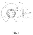
- Fig. 8 shows a plan view and a side view of the plate 570 and the bearing assembly 530.
- one of the keys 578, 578' of the plate 570 is shown as being received by a respective one of the keyways or notches 535, 535' of the bearing assembly 530.
- rotation of the outer race 532 of the bearing assembly 530 is restricted when positioned in the bore 515 of the center housing 510 as shown in Fig. 5 .
- keys can be integral to a thrust plate while corresponding keyways can be integral to an outer race of a bearing assembly.
- the keyways can be recessed from the OD of the outer race such that the centerless grind of the bearing OD does not encounter any discontinuities along the OD, near the raceway. If there were discontinuities on the OD during the centerless grind operation, machining imperfections on the OD would be created and subsequently transferred to the raceway grind (which is registered off the OD).
- the keyways 535, 535' are located outboard of the raceway for the rolling elements 536.
- a key received by each of the keyway 535, 535' may be configured to avoid contact axially (e.g., at an axial wall of a keyway). In such an example, a key only contacts a lateral wall or walls of a keyway (e.g., in the azimuthal direction).
- a keyway may be undercut on the outer diameter of an outer race of a bearing assembly and formed in a manner that avoids interference with a raceway (e.g., as bound by a low shoulder (face side) and a high or "deep" shoulder (back side)).
- a "ball band” may be formed by a ball riding over an edge of a raceway (e.g., which may be possibly caused by thrust forces).
- a keyway in an outer race are formed using a centerless grind operation where the one or more keyways are positioned to avoid risk of raceway/rolling element damage (e.g., via thrust, misalignment, loose fit, etc.).
- a keyway may be an OD relief of an outer race (e.g., for friendliness to a centerless grind operation).
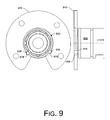
- Fig. 9 shows a plan view and a side view of a plate 970 and a bearing assembly 930.
- the plate 970 includes keyways 978, 978' and an outer race 932 of the bearing assembly 930 includes keys 935, 935'.
- the keys 935, 935' of the outer race 932 are shown as being received by the respective keyways 978, 978' of the plate 970. In such a manner, rotation of the outer race 932 of the bearing assembly 930 is restricted when positioned in a bore of a center housing.
- a plate may include one or more keys and one or more keyways.
- an outer race of a bearing may include one or more keys and one or more keyways.
- a key is received by a keyway.
- some keyways may be unfilled upon assembly. For example, consider an outer race with four keyways and a plate with two keys where two of the keyways remain unfilled upon assembly.
- a key/keyway pair (or pairs) provides a proscribed amount of freedom for a bearing assembly to move radially in a squeeze film damper (e.g., as formed between the outer race and bore of a housing).
- features of an outer race of a bearing assembly may act to locate the outer race with respect to one or more features of a housing.
- the bearing assembly 530 of Fig. 5 includes lubricant jets to direct lubricant from the lubricant well 513 to the rolling elements 536.
- one or more key/keyway pairs may act to locate the lubricant jets with respect to the lubricant well 513.
- such locating may be referred to as azimuthal locating that establishes a relationship between an assymetrical outer race and a housing (e.g., in an azimuthal direction, defined by a longitudinal axis of a bore of the housing).
- the exemplary locating mechanism of Figs. 5 , 6 , 7 , 8 and 9 allows for efficient machining of keys and keyways that act to limit rotational freedom of an outer race while maintaining low friction enabling radial freedom within its lubricant film and beneficial wear properties between key/keyway pairs.
- an exemplary method for locating an outer race of a bearing in a bore of a housing includes inserting the bearing in the bore of the housing; attaching a plate to the housing to at least partially axially locate the bearing in the bore of the housing; and restricting rotation of the outer race of the bearing in the bore of the housing by contacting an axially extending key and a keyway.
- the plate may include the key and the bearing may include the keyway or, alternatively, the outer race of the bearing may include the key and the plate may include the keyway.
- the contacting optionally azimuthally locates one or more lubricant jets of the outer race of the bearing with respect to a lubricant well of the housing.
- the plate may receive axial thrust forces without an axial end of the key contacting an axial end of the keyway (e.g., to avoid wear on the key and/or keyway).
Abstract
Description
- Subject matter disclosed herein relates generally to turbomachinery for internal combustion engines and, in particular, to techniques for locating a bearing assembly in a bore of a turbocharger.
- A conventional turbocharger typically relies on a center housing rotating assembly (CHRA) that includes a turbine wheel and a compressor wheel attached to a shaft rotatably supported by a bearing assembly located in a bore of a center housing. A typical bearing assembly or bearing cartridge includes an outer race and an inner race, configured to receive a shaft, where the outer race and the inner race are separated by rolling elements such as ball bearings.
- In most CHRAs, a so-called "locating mechanism" restricts movement of a bearing assembly in the bore of the center housing. Various conventional locating mechanisms rely on radial insertion of a locating pin in an opening of an outer race of a bearing assembly. Such a mechanism restricts radial and/or axial movement of the bearing assembly and rotation of the outer race yet allows the inner race to spin freely. Additionally, such a mechanism allows for some radial movement of a bearing assembly, usually within defined clearances that fill with lubricant during operation to form a "squeeze film" that acts to damp vibration and noise. In such a CHRA, the degrees of radial and axial freedom may be chosen to be of particular magnitude or magnitudes depending on various goals.
- Various issues can arise with locating mechanisms that rely on a radial locating pin to locate a bearing assembly. For example, during operation of a turbocharger, significant axial loads can be generated that thrust the turbocharger shaft and associated components toward the compressor end or toward the turbine end of the turbocharger CHRA, which, in turn, can be transferred from the bearing assembly to the radial locating pin. Such forces make pin strength an important design factor. Another issue pertains to axial stack-up of components (e.g., how well do the components of a CHRA stack and how does this stacking affect operation and wear). In general, a locating mechanism that relies on a radial locating pin does not provide advantages with respect to axial stacking; indeed, the nature of the pin and the outer race opening introduce geometric and operation concerns that can be disadvantageous.
- More generally, a locating mechanism, such as the aforementioned radial pin locating mechanism, can be described in terms of "key/keyway pairs" that involve male (key) and female (keyway) components that act to locate an outer race of a bearing assembly. In such key/keyway-based locating mechanisms, frictional contact between key and keyway components should remain low (1) to allow a bearing assembly to move freely in the radial plane (i.e., within its squeeze film) and (2) to limit wear between the keyway components.
- Additionally, in a CHRA, to maximize efficiency and reduce powerloss, frictional contact between components should be minimized. For turbochargers, the one source of powerloss stems from the bearing system. As described herein, various exemplary locating mechanisms can reduce or alleviate issues associated with locating mechanisms that rely on radial pins. For example, by reducing friction, such exemplary mechanisms can reduce powerloss and thereby improve efficiency and performance of turbocharged internal combustion engines.
- A more complete understanding of the various methods, devices, systems, arrangements, etc., described herein, and equivalents thereof, may be had by reference to the following detailed description when taken in conjunction with the accompanying drawings wherein:
-
Fig. 1 is a diagram of a turbocharger and an internal combustion engine. -
Fig. 2 is a cutaway perspective view of an exemplary turbocharger, along a plane defined by a line labeled A-A, which includes an anti-rotation mechanism for an outer race of a bearing assembly. -
Fig. 3 is an end view of the turbocharger ofFig. 2 along a plane defined by a line labeled B-B, which includes the anti-rotation mechanism;Fig. 3 also shows an example of a variation of the anti-rotation mechanism. -
Fig. 4 is a cross-sectional view of the turbocharger ofFig. 2 , along the plane defined by the line A-A, and an enlarged cross-sectional view, along a plane defined by a line labeled C-C inFig. 2 , which includes the anti-rotation mechanism. -
Fig. 5 is a cross-sectional view of a turbocharger and a cross-sectional view of a plate with integral key components of an anti-rotation mechanism, along a plane defined by a line labeled D-D. -
Fig. 6 is a plan view and a side view of the plate ofFig. 5 . -
Fig. 7 is a plan view and a cross-sectional view of a bearing assembly of the turbocharger ofFig. 5 , along a plane defined by a line labeled E-E inFig. 7 . -
Fig. 8 is a plan view and a side view of the plate ofFig. 6 and the bearing assembly ofFig. 7 . -
Fig. 9 is a plan view and a side view of a plate and the bearing assembly where the plate includes a keyway and the bearing assembly includes a key. - Turbochargers are frequently utilized to increase output of an internal combustion engine. Referring to
Fig. 1 , aconventional system 100 includes aninternal combustion engine 110 and aturbocharger 120. Theinternal combustion engine 110 includes an engine block 118 housing one or more combustion chambers that operatively drive ashaft 112. As shown inFig. 1 , anintake port 114 provides a flow path for air to the engine block 118 while anexhaust port 116 provides a flow path for exhaust from the engine block 118. - The
turbocharger 120 acts to extract energy from the exhaust and to provide energy to intake air, which may be combined with fuel to form combustion gas. As shown inFig. 1 , theturbocharger 120 includes anair inlet 134, ashaft 122, acompressor 124, aturbine 126, ahousing 128 and anexhaust outlet 136. Thehousing 128 may be referred to as a center housing as it is disposed between thecompressor 124 and theturbine 126. Theshaft 122 may be a shaft assembly that includes a variety of components. - Referring to the
turbine 126, such a turbine optionally includes a variable geometry unit and a variable geometry controller. The variable geometry unit and variable geometry controller optionally include features such as those associated with commercially available variable geometry turbochargers (VGTs). Commercially available VGTs include, for example, the GARRETT® VNT™ and AVNT™ turbochargers, which use multiple adjustable vanes to control the flow of exhaust across a turbine. An exemplary turbocharger may employ wastegate technology as an alternative or in addition to variable geometry technology. -
Fig. 2 shows a cross-sectional perspective view of anexemplary turbocharger 200 where a plane defined by a line A-A, a plane defined by a line B-B and a plane defined by a line C-C are shown. The A-A plane is the cross-sectional plane of the view ofFig. 2 whereas a view for the B-B plane is shown inFig. 3 and a view for the C-C is shown inFig. 4 . - The
turbocharger 200 serves as a non-limiting example to describe various exemplary devices, methods, systems, etc., disclosed herein. Theturbocharger 200 includes acenter housing 210, ashaft 220, abearing assembly 230, acompressor section 240, aturbine section 260 and a locating mechanism that includes aplate 270 and ananti-rotation component 280. - The
compressor section 240 includes acompressor housing 241 that houses acompressor wheel 242 that includes ahub 243 andblades 244. Theturbine section 260 includes aturbine housing 261 that houses aturbine wheel 262 that includes ahub 263 andblades 264. As shown, thecompressor wheel 242 and theturbine wheel 262 are operably connected to theshaft 220. Theshaft 220 may be made of multiple components that form a single operable shaft unit. Thecompressor wheel 240, theturbine wheel 260 and theshaft 220 have an axis of rotation substantially coincident with the z-axis. Thecenter housing 210 includes abore 215 that is configured to receive abearing assembly 230, which, in turn, receives theshaft 220 and allows for rotation of theshaft 220 about the z-axis. - As shown in the example of
Fig. 2 , thecenter housing 210 includes lubricant pathways to allow lubricant to flow to and from thebearing assembly 230. Specifically, thehousing 210 includes alubricant inlet 212 and alubricant outlet 216. Intermediate thelubricant inlet 212 and thelubricant outlet 216 are various features that define one or more lubricant flow paths. Anaxial lubricant path 213 is configured to direct lubricant from thelubricant inlet 212 to openings along thebore 215 of thecenter housing 210. As configured, lubricant can flow within the center housing 210 (e.g., enter the bearing assembly 230) and ultimately drain from the housing via the lubricant outlet 216 (e.g., due to gravity). - With respect to the locating mechanism, four components or features thereof are involved: (1) a
stop 211 of thecenter housing 210, positioned at a turbine end of thebore 215; (2) theplate 270 attached to thecenter housing 210, positioned at a compressor end of thebore 213; (iii) a recess in the center housing 210 (seeFigs. 3 and4 ); and (iv) theanti-rotation component 280, which may be positioned at any of a variety of locations along the length of an outer race of a bearing assembly. In the example ofFig. 2 , theanti-rotation component 280 is shown as being positioned at the compressor end of thebore 215 and adjacent a compressor end of thebearing assembly 230 where at least a portion of theanti-rotation component 280 is seated in a recess of thecenter housing 210. -
Fig. 3 shows a view of theturbocharger 200 from the B-B plane. Specifically,Fig. 3 shows thecenter housing 210, arecess 217 in thecenter housing 210, theshaft 220, thebearing assembly 230 and theanti-rotation component 280. Thebearing assembly 230 includes anouter race 232, aninner race 234 androlling elements 236. In the view ofFig. 3 , theaxial lubricant path 213 and thebore 215 are shown along with four apertures to receive bolts or the like to attach theplate 270 to thecenter housing 210. - In the example of
Fig. 3 , theouter race 232 includes a notched orkeyway portion 233 that cooperates with a key portion of theanti-rotation component 280. As shown, thecenter housing 210 has a beveled edge at the compressor end of thebore 215 and therecess 217 is positioned adjacent thebore 215. Theanti-rotation component 280 is seated in therecess 217, which is configured to limit rotation of theanti-rotation component 280. Specifically, therecess 217 and the anti-rotation component both have an oblong shape where that of therecess 217 is slightly larger in widthwise dimension than a corresponding dimension of theanti-rotation component 280, which while allowing for some movement, restricts excessive movement of theanti-rotation component 280 in therecess 217. - In the example of
Fig. 3 , theanti-rotation component 280 has an outer radius RC and a width WC while therecess 217 has an outer radius RR and a width WR. As shown, these 2D dimensions of therecess 217 exceed those of theanti-rotation component 280. WhileFig. 3 shows a particular configuration and shape, as described herein, other configurations and shapes may be used (see, e.g., the example 290). The example ofFig. 3 also shows an offset between an axis of rotation of theshaft 220 and an axis of rotation of theanti-rotation component 280.
In this example, theanti-rotation component 280, as received by therecess 217, limits rotation of theouter race 232 about the axis of rotation of theshaft 220. The amount of rotation of theouter race 232 may be determined wholly or in part by one or more factors such as dimensions of therecess 217, dimensions of theanti-rotation component 280, dimensions of thekeyway 233, etc. - In the example of
Fig. 3 , a point or points of contact exist between thekeyway 233 and an edge of theanti-rotation component 280. Further, a point or points of contact exist between theanti-rotation component 280 and, for example, an axial wall of thecenter housing 210 that defines therecess 217. In the example ofFig. 3 , contact between theanti-rotation component 280 and thecenter housing 210 counteract force exerted by contact between theouter race 232 and theanti-rotation component 280. Further, theanti-rotation component 280 as configured inFig. 3 , can restrict rotation of theouter race 232 in either clockwise or counter-clockwise directions. To do so, theanti-rotation component 280 can rotate (e.g., clockwise or counter-clockwise about an axis) as seated in therecess 217. - As a key with restricted movement, the
anti-rotation component 280, when seated at least partially in thekeyway portion 233 of theouter race 232, restricts rotational movement of theouter race 232. Hence, the aforementioned features restrict rotation of the bearingassembly 230 in thebore 215 of thecenter housing 210 without resorting to a radial locating pin. Further, as theanti-rotation component 280 is covered by theplate 270, axial thrust forces received by the anti-rotation component 280 (if any) can be transmitted to theplate 270. Specifically, depending on the relationship between the depth of thekeyway 233, therecess 217 and the thickness of theanti-rotation component 280, it is possible to ensure that no significant axial thrust forces are transmitted to theanti-rotation component 280. In such a configuration, theanti-rotation component 280 has no or little detrimental effect as to axial stacking of the components of a CHRA. -
Fig. 3 also shows anexemplary anti-rotation mechanism 290 where an anti-rotation component 296 (key) includes a curved edge (e.g., convex) and where abearing 291 include anouter race 292 with a curved edge 293 (e.g., concave, defining a keyway). Further, themechanism 290 includes arecess 297 having a shape (e.g. boundary) that acts to prevent or limit rotation of theanti-rotation component 296. In the examples ofFig. 3 , the anti-rotation mechanisms may be referred to as including key/keyway pairs. - As described herein, an exemplary anti-rotation mechanism includes a feature associated with an outer race and another complimentary feature where the two features act as a key and keyway pair to limit rotation of the outer race.
-
Fig. 4 shows a cross-sectional view (along the A-A plane) of some of the components of theturbocharger 200 ofFig. 2 and an enlarged cross-sectional view of theanti-rotation component 280 in along the C-C plane as indicated inFig. 2 . - In the C-C plane view, the
anti-rotation component 280 is shown as including ahead portion 282 and ashaft portion 284. In the example ofFig. 4 , thehead portion 282 is seated in therecess 217 while theshaft portion 284 is seated in anaxial bore 218. As described herein, theshaft portion 284 may loosely fit, tightly press fit, thread fit, etc., in theaxial bore 218. - As shown in the C-C plane view, the
plate 270 covers at least a part of thehead portion 282 of theanti-rotation component 280. As mentioned, if axial thrust forces are received by theanti-rotation component 280, they may be transferred to the plate 270 (e.g., which may be referred to as a cover plate). - While not shown in the views of
Figs. 2 ,3 and4 , theplate 270 can include apertures that allow for use of blots or the like to attach theplate 270 to thecenter housing 210. As shown inFig. 4 , anotherplate 250, referred to as a compressor wheel plate, is seated over theplate 270. In the example ofFig. 4 , disposed between thecompressor plate 250 and the locatingplate 270 is athrust collar 255. As shown, thethrust collar 250 can receive axial thrust forces from the shaft 220 (or inner race 234) and transfer these forces to thecompressor plate 250. Thrust forces received by theouter race 232 can be transferred to the locatingplate 270, which is attached to thecenter housing 210. Again, in various configurations, axial thrust received by theanti-rotation component 280 may be minimal or minimized. - As indicated in the C-C plane view of
Fig. 4 , thekeyway feature 233 of theouter race 232 doe not interfere with the raceway of the inner surface of theouter race 232. - As described herein, another exemplary anti-rotation mechanism relies on a plate that includes or seats one or more anti-rotation keys for receipt by one or more corresponding keyways (e.g., notches) in an outer race of a bearing assembly.
Fig. 5 shows cross-sectional views of various components of anexemplary CHRA 500 including acenter housing 510, ashaft 520, a bearingassembly 530, athrust collar 555 and aplate 570. The center housing includes a stop 511 (e.g., an opening with an arc or a diameter smaller than the outer diameter of an outer race), alubricant inlet 512, alubricant well 513, abore 515 and alubricant outlet 516. The bearingassembly 530 includes anouter race 532, aninner race 534 and various rollingelements 536 disposed therebetween, which allows theinner race 534 to spin freely. As shown theinner race 534, which may be a multi-component inner race, receives ashaft 520 which attaches to a turbine wheel at a turbine end (right side) and a compressor wheel at a compressor end (left side). - In the example of
Fig. 5 , thestop 511 and theplate 570 act to axially locate the bearingassembly 530 in thebore 515 of thecenter housing 510. Specifically, thestop 511 restricts axial movement of theouter race 532 at the turbine end of thebore 515 while theplate 570 restricts axial movement of theouter race 532 at the compressor end of thebore 515. In the cross-sectional view along a plane defined by a line D-D, theplate 570 is shown as being attached to thecenter housing 510 via abolt 590 that is inserted into thecenter housing 510 via anaperture 572 of theplate 570. Thecenter housing 510 can include various openings with threads or other features to receive thebolt 590 or other attachment component (see, e.g.,items 219 in the example ofFig. 3 ). - Details of the anti-rotation mechanism associated with the
plate 570 are shown inFigs. 6 ,7 and8 . Specifically,Fig. 6 shows features of theplate 570,Fig. 7 shows features of the bearingassembly 530 andFig. 8 shows how features of theplate 570 and the bearingassembly 530 cooperate to restrict rotation of theouter race 532 of the bearingassembly 530. -
Fig. 6 shows a plan view and a side view of theplate 570 ofFig. 5 along with a central z-axis for reference (see the z-axis of rotation of theshaft 520 inFig. 5 ). In the example ofFig. 6 , theplate 570 includes a cutout spanning angle X about the z-axis, a plurality ofapertures 572, anarced notch 574 at a radius RN, an opening at a radius RO, and twokeys 578, 578' positioned at an angle Y about the z-axis. -
Fig. 7 shows a side view and a cross-sectional view of theexemplary bearing assembly 530 ofFig. 5 . In the side view,keyways 535 and 535' are shown in theouter race 532. In the views ofFig. 7 , thekeyways 535, 535' are shown as being inset from an outer diameter of theouter race 532. Specifically, an inset diameter is labeled "DInset", which is less than an adjacent outer diameter. In the example ofFig. 7 , the opposing end of the bearingassembly 530 does not include a section with an inset diameter. As shown inFig. 5 , the opposing end cooperates with thestop 511 of thecenter housing 510 to restrict axial movement of the bearingassembly 530. -
Fig. 8 shows a plan view and a side view of theplate 570 and the bearingassembly 530. InFig. 8 , one of thekeys 578, 578' of theplate 570 is shown as being received by a respective one of the keyways ornotches 535, 535' of the bearingassembly 530. In such a manner, rotation of theouter race 532 of the bearingassembly 530 is restricted when positioned in thebore 515 of thecenter housing 510 as shown inFig. 5 . - In the examples of
Figs. 5 ,6 ,7 and8 , keys can be integral to a thrust plate while corresponding keyways can be integral to an outer race of a bearing assembly. As explained with respect toFig. 7 , the keyways can be recessed from the OD of the outer race such that the centerless grind of the bearing OD does not encounter any discontinuities along the OD, near the raceway. If there were discontinuities on the OD during the centerless grind operation, machining imperfections on the OD would be created and subsequently transferred to the raceway grind (which is registered off the OD). - As shown in
Fig. 7 , thekeyways 535, 535' are located outboard of the raceway for the rollingelements 536. A key received by each of thekeyway 535, 535' may be configured to avoid contact axially (e.g., at an axial wall of a keyway). In such an example, a key only contacts a lateral wall or walls of a keyway (e.g., in the azimuthal direction). As described herein, a keyway may be undercut on the outer diameter of an outer race of a bearing assembly and formed in a manner that avoids interference with a raceway (e.g., as bound by a low shoulder (face side) and a high or "deep" shoulder (back side)). For example, a "ball band" may be formed by a ball riding over an edge of a raceway (e.g., which may be possibly caused by thrust forces). Hence, in various examples, one or more keyways in an outer race are formed using a centerless grind operation where the one or more keyways are positioned to avoid risk of raceway/rolling element damage (e.g., via thrust, misalignment, loose fit, etc.). As described herein, a keyway may be an OD relief of an outer race (e.g., for friendliness to a centerless grind operation). -
Fig. 9 shows a plan view and a side view of aplate 970 and a bearing assembly 930. InFig. 9 , theplate 970 includeskeyways 978, 978' and anouter race 932 of the bearing assembly 930 includeskeys 935, 935'. Thekeys 935, 935' of theouter race 932 are shown as being received by therespective keyways 978, 978' of theplate 970. In such a manner, rotation of theouter race 932 of the bearing assembly 930 is restricted when positioned in a bore of a center housing. - In various examples, a plate may include one or more keys and one or more keyways. In various examples, an outer race of a bearing may include one or more keys and one or more keyways. In such examples, a key is received by a keyway. Various examples exist where depending on number of keys and keyways, some keyways may be unfilled upon assembly. For example, consider an outer race with four keyways and a plate with two keys where two of the keyways remain unfilled upon assembly. In various examples, a key/keyway pair (or pairs) provides a proscribed amount of freedom for a bearing assembly to move radially in a squeeze film damper (e.g., as formed between the outer race and bore of a housing).
- As described herein, features of an outer race of a bearing assembly may act to locate the outer race with respect to one or more features of a housing. For example, the bearing
assembly 530 ofFig. 5 includes lubricant jets to direct lubricant from the lubricant well 513 to the rollingelements 536. In such an example, one or more key/keyway pairs may act to locate the lubricant jets with respect to thelubricant well 513. In general, such locating may be referred to as azimuthal locating that establishes a relationship between an assymetrical outer race and a housing (e.g., in an azimuthal direction, defined by a longitudinal axis of a bore of the housing). - As described, the exemplary locating mechanism of
Figs. 5 ,6 ,7 ,8 and9 allows for efficient machining of keys and keyways that act to limit rotational freedom of an outer race while maintaining low friction enabling radial freedom within its lubricant film and beneficial wear properties between key/keyway pairs. - As described herein, an exemplary method for locating an outer race of a bearing in a bore of a housing includes inserting the bearing in the bore of the housing; attaching a plate to the housing to at least partially axially locate the bearing in the bore of the housing; and restricting rotation of the outer race of the bearing in the bore of the housing by contacting an axially extending key and a keyway. In such a method, the plate may include the key and the bearing may include the keyway or, alternatively, the outer race of the bearing may include the key and the plate may include the keyway. In such a method, the contacting optionally azimuthally locates one or more lubricant jets of the outer race of the bearing with respect to a lubricant well of the housing. In such a method, the plate may receive axial thrust forces without an axial end of the key contacting an axial end of the keyway (e.g., to avoid wear on the key and/or keyway).
- Although some exemplary methods, devices, systems, arrangements, etc., have been illustrated in the accompanying Drawings and described in the foregoing Detailed Description, it will be understood that the exemplary embodiments disclosed are not limiting, but are capable of numerous rearrangements, modifications and substitutions without departing from the spirit set forth and defined by the following claims.
Claims (10)
- A center housing rotating assembly comprising:a turbine wheel;a compressor wheel;a center housing (510) that comprises a through bore (515), extending from a compressor end to a turbine end along a bore axis;a bearing assembly (530) positioned in the bore wherein the bearing assembly comprises an outer race (532) that comprises keyways (535, 535') extending axially from an axial end, the keyways radially inset from an outer diameter of the outer race; anda plate (570) attached to the center housing wherein the plate comprises axially extending keys (578, 578'), each of the keys (578, 578') being received by a respective one of the keyways (535, 535') to restrict rotation of the bearing assembly in the bore.
- The center housing rotating assembly of claim 1 wherein the outer race (532) comprises an asymmetric outer race and wherein the keys (578, 578') in conjunction with the keyways (535, 535') azimuthally locate the outer race with respect to one or more features of the through bore (515).
- The center housing rotating assembly of claim 2 wherein one of the one or more features of the through bore comprises a lubricant well, wherein the outer race (532) comprises lubricant jets and wherein the keys (578, 578') in conjunction with the keyways (535, 535') azimuthally locate the lubricant jets with respect to the lubricant well.
- A center housing rotating assembly comprising:a turbine wheel;a compressor wheel;a center housing that comprises a through bore, extending from a compressor end to a turbine end along a bore axis;a bearing assembly (930) positioned in the bore wherein the bearing assembly comprises an outer race (932) that comprises keys (935, 935') extending axially from an axial end; anda plate (970) attached to the center housing wherein the plate comprises axially extending keyways (978, 978'), each of the keys (935, 935') being received by a respective one of the keyways (978, 978') to restrict rotation of the bearing assembly in the bore.
- The center housing rotating assembly of claim 4 wherein the outer race (932) comprises an asymmetric outer race and wherein the keys (935, 935') and the keyways (978, 978') azimuthally locate the outer race with respect to one or more features of the through bore.
- The center housing rotating assembly of claim 5 wherein one of the one or more features of the through bore comprises a lubricant well, wherein the outer race (932) comprises lubricant jets and wherein the keys (935, 935') in conjunction with the keyways (975, 975') azimuthally locate the lubricant jets with respect to the lubricant well.
- A method for locating an outer race of a bearing in a bore of a housing, the method comprising:inserting the bearing in the bore of the housing;attaching a plate to the housing to at least partially axially locate the bearing in the bore of the housing;restricting rotation of the outer race of the bearing in the bore of the housing by contacting an axially extending key and a keyway.
- The method of claim 7 wherein the plate comprises the key and wherein the bearing comprises the keyway.
- The method of claim 7 wherein the outer race of the bearing comprises the key and wherein the plate comprises the keyway.
- The method of claim 7 wherein the contacting azimuthally locates one or more lubricant jets of the outer race of the bearing with respect to a lubricant well of the housing.
Applications Claiming Priority (1)
| Application Number | Priority Date | Filing Date | Title |
|---|---|---|---|
| US12/547,740 US8961128B2 (en) | 2009-08-26 | 2009-08-26 | Bearing spacer and housing |
Publications (3)
| Publication Number | Publication Date |
|---|---|
| EP2290198A2 true EP2290198A2 (en) | 2011-03-02 |
| EP2290198A3 EP2290198A3 (en) | 2014-04-16 |
| EP2290198B1 EP2290198B1 (en) | 2016-06-29 |
Family
ID=42543029
Family Applications (1)
| Application Number | Title | Priority Date | Filing Date |
|---|---|---|---|
| EP10172023.3A Active EP2290198B1 (en) | 2009-08-26 | 2010-08-05 | Bearing spacer and housing |
Country Status (3)
| Country | Link |
|---|---|
| US (1) | US8961128B2 (en) |
| EP (1) | EP2290198B1 (en) |
| CN (1) | CN102003227B (en) |
Cited By (4)
| Publication number | Priority date | Publication date | Assignee | Title |
|---|---|---|---|---|
| CN104395561A (en) * | 2012-06-21 | 2015-03-04 | 易安迪机车公司 | Turbocharger support housing having improved drainage |
| EP2850300A4 (en) * | 2012-05-15 | 2016-02-17 | Honeywell Int Inc | Turbocharger with journal bearing |
| EP2706197A3 (en) * | 2012-09-11 | 2017-08-30 | Honeywell International Inc. | Outer race locating washer |
| EP3575620A1 (en) * | 2018-05-25 | 2019-12-04 | Borgwarner Inc. | Single-row ball bearing with integrated squeeze-film damper |
Families Citing this family (38)
| Publication number | Priority date | Publication date | Assignee | Title |
|---|---|---|---|---|
| WO2010123762A2 (en) * | 2009-04-20 | 2010-10-28 | Borgwarner Inc. | Anti-rotation method for a rolling element bearing cartridge |
| DE102009053101B4 (en) * | 2009-11-13 | 2016-02-25 | Continental Automotive Gmbh | Turbocharger with a turbocharger housing and a receiving device for the rotor of the turbocharger |
| DE102010054905A1 (en) * | 2010-12-17 | 2012-06-21 | Schaeffler Technologies Gmbh & Co. Kg | Bearing unit for a turbocharger |
| CN103518049B (en) * | 2011-05-10 | 2017-05-17 | 博格华纳公司 | Exhaust-gas turbocharger and bearing shell thereof |
| EP2535526B1 (en) * | 2011-06-17 | 2013-10-30 | Aktiebolaget SKF | Turbocharger, notably for a combustion engine. |
| US20130014503A1 (en) * | 2011-07-15 | 2013-01-17 | GM Global Technology Operations LLC | Housing assembly for forced air induction system |
| JP6236440B2 (en) * | 2012-06-25 | 2017-11-22 | ボーグワーナー インコーポレーテッド | Exhaust gas turbocharger |
| IN2015DN00471A (en) * | 2012-07-12 | 2015-06-26 | Borgwarner Inc | |
| WO2015088634A1 (en) * | 2013-12-13 | 2015-06-18 | United Technologies Corporation | Bearing outer race oil supply for thin film fluidic damping |
| CN104713601A (en) * | 2013-12-17 | 2015-06-17 | 奚勇 | Self-rotating flowmeter |
| DE102014213330A1 (en) * | 2014-07-09 | 2016-01-14 | Bosch Mahle Turbo Systems Gmbh & Co. Kg | loader |
| US9897097B2 (en) * | 2015-01-22 | 2018-02-20 | GM Global Technology Operations LLC | Turbocharger with a hybrid journal bearing system |
| US20160236511A1 (en) * | 2015-02-13 | 2016-08-18 | Kic Llc | Extended length bearing cone system |
| US9890788B2 (en) | 2015-03-09 | 2018-02-13 | Caterpillar Inc. | Turbocharger and method |
| US9903225B2 (en) | 2015-03-09 | 2018-02-27 | Caterpillar Inc. | Turbocharger with low carbon steel shaft |
| US9638138B2 (en) | 2015-03-09 | 2017-05-02 | Caterpillar Inc. | Turbocharger and method |
| US10006341B2 (en) | 2015-03-09 | 2018-06-26 | Caterpillar Inc. | Compressor assembly having a diffuser ring with tabs |
| US9732633B2 (en) | 2015-03-09 | 2017-08-15 | Caterpillar Inc. | Turbocharger turbine assembly |
| US10066639B2 (en) | 2015-03-09 | 2018-09-04 | Caterpillar Inc. | Compressor assembly having a vaneless space |
| US9650913B2 (en) | 2015-03-09 | 2017-05-16 | Caterpillar Inc. | Turbocharger turbine containment structure |
| US9822700B2 (en) * | 2015-03-09 | 2017-11-21 | Caterpillar Inc. | Turbocharger with oil containment arrangement |
| US9683520B2 (en) | 2015-03-09 | 2017-06-20 | Caterpillar Inc. | Turbocharger and method |
| US9810238B2 (en) | 2015-03-09 | 2017-11-07 | Caterpillar Inc. | Turbocharger with turbine shroud |
| US9915172B2 (en) * | 2015-03-09 | 2018-03-13 | Caterpillar Inc. | Turbocharger with bearing piloted compressor wheel |
| US9739238B2 (en) | 2015-03-09 | 2017-08-22 | Caterpillar Inc. | Turbocharger and method |
| US9777747B2 (en) | 2015-03-09 | 2017-10-03 | Caterpillar Inc. | Turbocharger with dual-use mounting holes |
| US9879594B2 (en) | 2015-03-09 | 2018-01-30 | Caterpillar Inc. | Turbocharger turbine nozzle and containment structure |
| US9752536B2 (en) | 2015-03-09 | 2017-09-05 | Caterpillar Inc. | Turbocharger and method |
| JP6678086B2 (en) | 2016-08-12 | 2020-04-08 | ミネベアミツミ株式会社 | Rolling bearing and detent mechanism for turbocharger |
| US10330002B2 (en) * | 2016-12-12 | 2019-06-25 | Garrett Transportation I Inc. | Turbocharger assembly |
| US20200041053A1 (en) * | 2017-02-01 | 2020-02-06 | Borgwarner Inc. | Housing assembly for a turbocharger and method for fixing multiple connections to a housing |
| WO2019101974A1 (en) | 2017-11-24 | 2019-05-31 | Brp-Rotax Gmbh & Co. Kg | Turbocharger for an internal combustion engine |
| DE102017222918A1 (en) * | 2017-12-15 | 2019-06-19 | Aktiebolaget Skf | roller bearing assembly |
| CN111971462B (en) * | 2018-02-20 | 2023-01-10 | 三菱重工发动机和增压器株式会社 | Pressure booster |
| US11067131B2 (en) * | 2018-06-07 | 2021-07-20 | Borg Warner Inc. | Anti-rotation assembly and bearing housing assembly including the same |
| DE102020201186A1 (en) | 2020-01-31 | 2021-08-05 | Minebea Mitsumi Inc. | Fixing device for a rolling bearing ring, rolling bearing and exhaust gas turbine |
| DE102020201184A1 (en) | 2020-01-31 | 2021-08-05 | Minebea Mitsumi Inc. | Fixing device for a rolling bearing ring, rolling bearing and exhaust gas turbine |
| DE112020005650T5 (en) | 2020-02-20 | 2022-09-01 | Mitsubishi Heavy Industries Engine & Turbocharger, Ltd. | TURBOCHARGER |
Family Cites Families (27)
| Publication number | Priority date | Publication date | Assignee | Title |
|---|---|---|---|---|
| DE952756C (en) | 1953-02-24 | 1956-11-22 | Maschf Augsburg Nuernberg Ag | Exhaust gas turbo unit with flexible bearing of the rotor shaft |
| US3056634A (en) * | 1959-08-03 | 1962-10-02 | Schwitzer Corp | Bearing structure |
| US3672734A (en) * | 1970-07-23 | 1972-06-27 | Bando Kiko Co | Bearing adaptor |
| US4285632A (en) * | 1979-02-28 | 1981-08-25 | United Aircraft Products, Inc. | Oiling system for rotor bearings |
| JPS60116920A (en) * | 1983-11-30 | 1985-06-24 | Hitachi Ltd | Thrust bearing holding in rotary fluid machine |
| JPS6159016A (en) * | 1984-08-31 | 1986-03-26 | Ube Ind Ltd | Floating bush bearing |
| IT1185677B (en) * | 1984-09-03 | 1987-11-12 | Ishikawajima Harima Heavy Ind | SUPPORT DEVICE FOR EXHAUST GAS TURBOCHARGER |
| DE3601082A1 (en) | 1986-01-16 | 1987-07-23 | Kuehnle Kopp Kausch Ag | EXHAUST TURBOCHARGER |
| US4798523A (en) * | 1986-12-19 | 1989-01-17 | Allied-Signal Inc. | Turbocharger bearing and lubrication system |
| DE3712444A1 (en) | 1987-04-11 | 1988-10-27 | Kuehnle Kopp Kausch Ag | EXHAUST TURBOCHARGER STORAGE |
| JPH0540273Y2 (en) * | 1988-04-26 | 1993-10-13 | ||
| KR0154105B1 (en) * | 1989-10-30 | 1998-11-16 | 제랄드 피. 루니 | Turbocharger compressor wheel assembly with boreless hub compressor wheel |
| DE4002583C1 (en) | 1990-01-30 | 1991-05-29 | Aktiengesellschaft Kuehnle, Kopp & Kausch, 6710 Frankenthal, De | |
| US5067825A (en) * | 1990-06-18 | 1991-11-26 | Vance John M | Aircraft engine rotor squeeze film damper |
| US5048978A (en) * | 1991-01-14 | 1991-09-17 | General Electric Company | Squeeze film damper seal |
| US5890881A (en) * | 1996-11-27 | 1999-04-06 | Alliedsignal Inc. | Pressure balanced turbocharger rotating seal |
| US5887982A (en) * | 1997-06-17 | 1999-03-30 | U.S. Filter Wastewater Group, Inc. | Bearing assembly for use with a submerged apparatus and method for performing maintenance thereon |
| US5921683A (en) * | 1997-09-12 | 1999-07-13 | United Technologies Corporation | Bearing arrangement for air cycle machine |
| EP1174629A1 (en) | 2000-06-30 | 2002-01-23 | Techspace Aero S.A. | Sealing device of a squeeze film damper incorporated in a rolling element bearing |
| DE10135784B4 (en) * | 2000-07-26 | 2015-09-17 | Ntn Corp. | Bearing provided with a rotation sensor and motor equipped therewith |
| US6669372B1 (en) * | 2002-07-30 | 2003-12-30 | Honeywell International Inc. | Turbocharger thrust bearing |
| DE10357109A1 (en) * | 2003-12-06 | 2005-07-07 | Fag Kugelfischer Ag | bearing arrangement |
| JP2005172098A (en) | 2003-12-10 | 2005-06-30 | Koyo Seiko Co Ltd | Turbocharger bearing device |
| US7214037B2 (en) * | 2004-06-28 | 2007-05-08 | Honeywell International, Inc. | Retention of ball bearing cartridge for turbomachinery |
| US7753591B2 (en) * | 2005-06-30 | 2010-07-13 | Honeywell International Inc. | Turbocharger bearing and associated components |
| US7329048B2 (en) * | 2005-07-19 | 2008-02-12 | Rolls-Royce Corporation | Self contained squeeze film damping system |
| GB0708975D0 (en) * | 2007-05-10 | 2007-06-20 | Cummins Turbo Tech Ltd | Variable geometry turbine |
-
2009
- 2009-08-26 US US12/547,740 patent/US8961128B2/en active Active
-
2010
- 2010-08-05 EP EP10172023.3A patent/EP2290198B1/en active Active
- 2010-08-25 CN CN201010263754.8A patent/CN102003227B/en active Active
Non-Patent Citations (1)
| Title |
|---|
| None |
Cited By (6)
| Publication number | Priority date | Publication date | Assignee | Title |
|---|---|---|---|---|
| EP2850300A4 (en) * | 2012-05-15 | 2016-02-17 | Honeywell Int Inc | Turbocharger with journal bearing |
| US9810231B2 (en) | 2012-05-15 | 2017-11-07 | Honeywell International Inc. | Turbocharger with journal bearing |
| CN104395561A (en) * | 2012-06-21 | 2015-03-04 | 易安迪机车公司 | Turbocharger support housing having improved drainage |
| CN104395561B (en) * | 2012-06-21 | 2017-03-15 | 易安迪机车公司 | There is the turbocharger for improving discharge system to support housing |
| EP2706197A3 (en) * | 2012-09-11 | 2017-08-30 | Honeywell International Inc. | Outer race locating washer |
| EP3575620A1 (en) * | 2018-05-25 | 2019-12-04 | Borgwarner Inc. | Single-row ball bearing with integrated squeeze-film damper |
Also Published As
| Publication number | Publication date |
|---|---|
| US8961128B2 (en) | 2015-02-24 |
| EP2290198B1 (en) | 2016-06-29 |
| CN102003227A (en) | 2011-04-06 |
| CN102003227B (en) | 2015-07-08 |
| US20110052388A1 (en) | 2011-03-03 |
| EP2290198A3 (en) | 2014-04-16 |
Similar Documents
| Publication | Publication Date | Title |
|---|---|---|
| US9039391B2 (en) | Bearing spacer and housing | |
| US8961128B2 (en) | Bearing spacer and housing | |
| EP1972759B1 (en) | Stepped outer diameter semi-floating bearing | |
| EP3011179B1 (en) | Assembly with bearings and spacer | |
| EP1896696B1 (en) | Turbocharger bearing and associated components | |
| EP2208903B1 (en) | Bearing and retention mechanisms | |
| EP1805398B1 (en) | Turbocharger with thrust collar | |
| US9810231B2 (en) | Turbocharger with journal bearing | |
| EP2573362A2 (en) | Turbocharger comprising a sleeve | |
| EP3511577B1 (en) | Bearing assembly with damping features | |
| WO2016171933A1 (en) | Turbocharger spring assembly | |
| EP3081769A1 (en) | Turbocharger bearing assembly | |
| EP2706197B1 (en) | Bearing outer race locating washer | |
| JP2011149390A (en) | Supercharger |
Legal Events
| Date | Code | Title | Description |
|---|---|---|---|
| PUAI | Public reference made under article 153(3) epc to a published international application that has entered the european phase |
Free format text: ORIGINAL CODE: 0009012 |
|
| 17P | Request for examination filed |
Effective date: 20100805 |
|
| AK | Designated contracting states |
Kind code of ref document: A2 Designated state(s): AL AT BE BG CH CY CZ DE DK EE ES FI FR GB GR HR HU IE IS IT LI LT LU LV MC MK MT NL NO PL PT RO SE SI SK SM TR |
|
| AX | Request for extension of the european patent |
Extension state: BA ME RS |
|
| PUAL | Search report despatched |
Free format text: ORIGINAL CODE: 0009013 |
|
| AK | Designated contracting states |
Kind code of ref document: A3 Designated state(s): AL AT BE BG CH CY CZ DE DK EE ES FI FR GB GR HR HU IE IS IT LI LT LU LV MC MK MT NL NO PL PT RO SE SI SK SM TR |
|
| AX | Request for extension of the european patent |
Extension state: BA ME RS |
|
| RIC1 | Information provided on ipc code assigned before grant |
Ipc: F02C 6/12 20060101ALI20140307BHEP Ipc: F01D 25/16 20060101AFI20140307BHEP Ipc: F16C 35/00 20060101ALI20140307BHEP |
|
| 17Q | First examination report despatched |
Effective date: 20140408 |
|
| RAP1 | Party data changed (applicant data changed or rights of an application transferred) |
Owner name: HONEYWELL INTERNATIONAL INC. |
|
| REG | Reference to a national code |
Ref country code: DE Ref legal event code: R079 Ref document number: 602010034254 Country of ref document: DE Free format text: PREVIOUS MAIN CLASS: F01D0025160000 Ipc: F16C0035040000 |
|
| GRAP | Despatch of communication of intention to grant a patent |
Free format text: ORIGINAL CODE: EPIDOSNIGR1 |
|
| RIC1 | Information provided on ipc code assigned before grant |
Ipc: F16C 35/04 20060101AFI20160127BHEP Ipc: F02C 6/12 20060101ALI20160127BHEP Ipc: F01D 25/16 20060101ALI20160127BHEP |
|
| INTG | Intention to grant announced |
Effective date: 20160212 |
|
| GRAS | Grant fee paid |
Free format text: ORIGINAL CODE: EPIDOSNIGR3 |
|
| GRAA | (expected) grant |
Free format text: ORIGINAL CODE: 0009210 |
|
| AK | Designated contracting states |
Kind code of ref document: B1 Designated state(s): AL AT BE BG CH CY CZ DE DK EE ES FI FR GB GR HR HU IE IS IT LI LT LU LV MC MK MT NL NO PL PT RO SE SI SK SM TR |
|
| REG | Reference to a national code |
Ref country code: GB Ref legal event code: FG4D |
|
| REG | Reference to a national code |
Ref country code: CH Ref legal event code: EP |
|
| REG | Reference to a national code |
Ref country code: AT Ref legal event code: REF Ref document number: 809355 Country of ref document: AT Kind code of ref document: T Effective date: 20160715 |
|
| REG | Reference to a national code |
Ref country code: FR Ref legal event code: PLFP Year of fee payment: 7 |
|
| REG | Reference to a national code |
Ref country code: IE Ref legal event code: FG4D |
|
| REG | Reference to a national code |
Ref country code: DE Ref legal event code: R096 Ref document number: 602010034254 Country of ref document: DE |
|
| REG | Reference to a national code |
Ref country code: LT Ref legal event code: MG4D |
|
| PG25 | Lapsed in a contracting state [announced via postgrant information from national office to epo] |
Ref country code: FI Free format text: LAPSE BECAUSE OF FAILURE TO SUBMIT A TRANSLATION OF THE DESCRIPTION OR TO PAY THE FEE WITHIN THE PRESCRIBED TIME-LIMIT Effective date: 20160629 Ref country code: LT Free format text: LAPSE BECAUSE OF FAILURE TO SUBMIT A TRANSLATION OF THE DESCRIPTION OR TO PAY THE FEE WITHIN THE PRESCRIBED TIME-LIMIT Effective date: 20160629 Ref country code: NO Free format text: LAPSE BECAUSE OF FAILURE TO SUBMIT A TRANSLATION OF THE DESCRIPTION OR TO PAY THE FEE WITHIN THE PRESCRIBED TIME-LIMIT Effective date: 20160929 |
|
| REG | Reference to a national code |
Ref country code: NL Ref legal event code: MP Effective date: 20160629 |
|
| PG25 | Lapsed in a contracting state [announced via postgrant information from national office to epo] |
Ref country code: NL Free format text: LAPSE BECAUSE OF FAILURE TO SUBMIT A TRANSLATION OF THE DESCRIPTION OR TO PAY THE FEE WITHIN THE PRESCRIBED TIME-LIMIT Effective date: 20160629 Ref country code: LV Free format text: LAPSE BECAUSE OF FAILURE TO SUBMIT A TRANSLATION OF THE DESCRIPTION OR TO PAY THE FEE WITHIN THE PRESCRIBED TIME-LIMIT Effective date: 20160629 Ref country code: SE Free format text: LAPSE BECAUSE OF FAILURE TO SUBMIT A TRANSLATION OF THE DESCRIPTION OR TO PAY THE FEE WITHIN THE PRESCRIBED TIME-LIMIT Effective date: 20160629 Ref country code: HR Free format text: LAPSE BECAUSE OF FAILURE TO SUBMIT A TRANSLATION OF THE DESCRIPTION OR TO PAY THE FEE WITHIN THE PRESCRIBED TIME-LIMIT Effective date: 20160629 Ref country code: GR Free format text: LAPSE BECAUSE OF FAILURE TO SUBMIT A TRANSLATION OF THE DESCRIPTION OR TO PAY THE FEE WITHIN THE PRESCRIBED TIME-LIMIT Effective date: 20160930 |
|
| REG | Reference to a national code |
Ref country code: AT Ref legal event code: MK05 Ref document number: 809355 Country of ref document: AT Kind code of ref document: T Effective date: 20160629 |
|
| PG25 | Lapsed in a contracting state [announced via postgrant information from national office to epo] |
Ref country code: BE Free format text: LAPSE BECAUSE OF NON-PAYMENT OF DUE FEES Effective date: 20160831 |
|
| PG25 | Lapsed in a contracting state [announced via postgrant information from national office to epo] |
Ref country code: EE Free format text: LAPSE BECAUSE OF FAILURE TO SUBMIT A TRANSLATION OF THE DESCRIPTION OR TO PAY THE FEE WITHIN THE PRESCRIBED TIME-LIMIT Effective date: 20160629 Ref country code: SK Free format text: LAPSE BECAUSE OF FAILURE TO SUBMIT A TRANSLATION OF THE DESCRIPTION OR TO PAY THE FEE WITHIN THE PRESCRIBED TIME-LIMIT Effective date: 20160629 Ref country code: RO Free format text: LAPSE BECAUSE OF FAILURE TO SUBMIT A TRANSLATION OF THE DESCRIPTION OR TO PAY THE FEE WITHIN THE PRESCRIBED TIME-LIMIT Effective date: 20160629 Ref country code: IT Free format text: LAPSE BECAUSE OF FAILURE TO SUBMIT A TRANSLATION OF THE DESCRIPTION OR TO PAY THE FEE WITHIN THE PRESCRIBED TIME-LIMIT Effective date: 20160629 Ref country code: CZ Free format text: LAPSE BECAUSE OF FAILURE TO SUBMIT A TRANSLATION OF THE DESCRIPTION OR TO PAY THE FEE WITHIN THE PRESCRIBED TIME-LIMIT Effective date: 20160629 Ref country code: IS Free format text: LAPSE BECAUSE OF FAILURE TO SUBMIT A TRANSLATION OF THE DESCRIPTION OR TO PAY THE FEE WITHIN THE PRESCRIBED TIME-LIMIT Effective date: 20161029 |
|
| PG25 | Lapsed in a contracting state [announced via postgrant information from national office to epo] |
Ref country code: BE Free format text: LAPSE BECAUSE OF FAILURE TO SUBMIT A TRANSLATION OF THE DESCRIPTION OR TO PAY THE FEE WITHIN THE PRESCRIBED TIME-LIMIT Effective date: 20160629 Ref country code: AT Free format text: LAPSE BECAUSE OF FAILURE TO SUBMIT A TRANSLATION OF THE DESCRIPTION OR TO PAY THE FEE WITHIN THE PRESCRIBED TIME-LIMIT Effective date: 20160629 Ref country code: SM Free format text: LAPSE BECAUSE OF FAILURE TO SUBMIT A TRANSLATION OF THE DESCRIPTION OR TO PAY THE FEE WITHIN THE PRESCRIBED TIME-LIMIT Effective date: 20160629 Ref country code: PL Free format text: LAPSE BECAUSE OF FAILURE TO SUBMIT A TRANSLATION OF THE DESCRIPTION OR TO PAY THE FEE WITHIN THE PRESCRIBED TIME-LIMIT Effective date: 20160629 Ref country code: ES Free format text: LAPSE BECAUSE OF FAILURE TO SUBMIT A TRANSLATION OF THE DESCRIPTION OR TO PAY THE FEE WITHIN THE PRESCRIBED TIME-LIMIT Effective date: 20160629 Ref country code: PT Free format text: LAPSE BECAUSE OF FAILURE TO SUBMIT A TRANSLATION OF THE DESCRIPTION OR TO PAY THE FEE WITHIN THE PRESCRIBED TIME-LIMIT Effective date: 20161031 |
|
| REG | Reference to a national code |
Ref country code: DE Ref legal event code: R097 Ref document number: 602010034254 Country of ref document: DE |
|
| PG25 | Lapsed in a contracting state [announced via postgrant information from national office to epo] |
Ref country code: MC Free format text: LAPSE BECAUSE OF FAILURE TO SUBMIT A TRANSLATION OF THE DESCRIPTION OR TO PAY THE FEE WITHIN THE PRESCRIBED TIME-LIMIT Effective date: 20160629 |
|
| REG | Reference to a national code |
Ref country code: CH Ref legal event code: PL |
|
| PG25 | Lapsed in a contracting state [announced via postgrant information from national office to epo] |
Ref country code: CH Free format text: LAPSE BECAUSE OF NON-PAYMENT OF DUE FEES Effective date: 20160831 Ref country code: LI Free format text: LAPSE BECAUSE OF NON-PAYMENT OF DUE FEES Effective date: 20160831 |
|
| PLBE | No opposition filed within time limit |
Free format text: ORIGINAL CODE: 0009261 |
|
| STAA | Information on the status of an ep patent application or granted ep patent |
Free format text: STATUS: NO OPPOSITION FILED WITHIN TIME LIMIT |
|
| PG25 | Lapsed in a contracting state [announced via postgrant information from national office to epo] |
Ref country code: DK Free format text: LAPSE BECAUSE OF FAILURE TO SUBMIT A TRANSLATION OF THE DESCRIPTION OR TO PAY THE FEE WITHIN THE PRESCRIBED TIME-LIMIT Effective date: 20160629 |
|
| REG | Reference to a national code |
Ref country code: IE Ref legal event code: MM4A |
|
| 26N | No opposition filed |
Effective date: 20170330 |
|
| STAA | Information on the status of an ep patent application or granted ep patent |
Free format text: STATUS: NO OPPOSITION FILED WITHIN TIME LIMIT |
|
| PG25 | Lapsed in a contracting state [announced via postgrant information from national office to epo] |
Ref country code: IE Free format text: LAPSE BECAUSE OF NON-PAYMENT OF DUE FEES Effective date: 20160805 |
|
| REG | Reference to a national code |
Ref country code: FR Ref legal event code: PLFP Year of fee payment: 8 |
|
| PG25 | Lapsed in a contracting state [announced via postgrant information from national office to epo] |
Ref country code: LU Free format text: LAPSE BECAUSE OF NON-PAYMENT OF DUE FEES Effective date: 20160805 Ref country code: SI Free format text: LAPSE BECAUSE OF FAILURE TO SUBMIT A TRANSLATION OF THE DESCRIPTION OR TO PAY THE FEE WITHIN THE PRESCRIBED TIME-LIMIT Effective date: 20160629 Ref country code: BG Free format text: LAPSE BECAUSE OF FAILURE TO SUBMIT A TRANSLATION OF THE DESCRIPTION OR TO PAY THE FEE WITHIN THE PRESCRIBED TIME-LIMIT Effective date: 20160929 |
|
| PG25 | Lapsed in a contracting state [announced via postgrant information from national office to epo] |
Ref country code: CY Free format text: LAPSE BECAUSE OF FAILURE TO SUBMIT A TRANSLATION OF THE DESCRIPTION OR TO PAY THE FEE WITHIN THE PRESCRIBED TIME-LIMIT Effective date: 20160629 Ref country code: HU Free format text: LAPSE BECAUSE OF FAILURE TO SUBMIT A TRANSLATION OF THE DESCRIPTION OR TO PAY THE FEE WITHIN THE PRESCRIBED TIME-LIMIT; INVALID AB INITIO Effective date: 20100805 |
|
| PG25 | Lapsed in a contracting state [announced via postgrant information from national office to epo] |
Ref country code: MT Free format text: LAPSE BECAUSE OF NON-PAYMENT OF DUE FEES Effective date: 20160831 Ref country code: MK Free format text: LAPSE BECAUSE OF FAILURE TO SUBMIT A TRANSLATION OF THE DESCRIPTION OR TO PAY THE FEE WITHIN THE PRESCRIBED TIME-LIMIT Effective date: 20160629 Ref country code: TR Free format text: LAPSE BECAUSE OF FAILURE TO SUBMIT A TRANSLATION OF THE DESCRIPTION OR TO PAY THE FEE WITHIN THE PRESCRIBED TIME-LIMIT Effective date: 20160629 |
|
| REG | Reference to a national code |
Ref country code: FR Ref legal event code: PLFP Year of fee payment: 9 |
|
| PG25 | Lapsed in a contracting state [announced via postgrant information from national office to epo] |
Ref country code: AL Free format text: LAPSE BECAUSE OF FAILURE TO SUBMIT A TRANSLATION OF THE DESCRIPTION OR TO PAY THE FEE WITHIN THE PRESCRIBED TIME-LIMIT Effective date: 20160629 |
|
| REG | Reference to a national code |
Ref country code: DE Ref legal event code: R081 Ref document number: 602010034254 Country of ref document: DE Owner name: GARRETT TRANSPORTATION I INC., TORRANCE, US Free format text: FORMER OWNER: HONEYWELL INTERNATIONAL INC., MORRIS PLAINS, N.J., US |
|
| REG | Reference to a national code |
Ref country code: GB Ref legal event code: 732E Free format text: REGISTERED BETWEEN 20190725 AND 20190731 |
|
| PGFP | Annual fee paid to national office [announced via postgrant information from national office to epo] |
Ref country code: GB Payment date: 20230822 Year of fee payment: 14 |
|
| PGFP | Annual fee paid to national office [announced via postgrant information from national office to epo] |
Ref country code: FR Payment date: 20230824 Year of fee payment: 14 Ref country code: DE Payment date: 20230828 Year of fee payment: 14 |