EP2290190A1 - Method and apparatus for controlled bidirectional movement of an oilfield tool in a wellbore environment - Google Patents
Method and apparatus for controlled bidirectional movement of an oilfield tool in a wellbore environment Download PDFInfo
- Publication number
- EP2290190A1 EP2290190A1 EP09290658A EP09290658A EP2290190A1 EP 2290190 A1 EP2290190 A1 EP 2290190A1 EP 09290658 A EP09290658 A EP 09290658A EP 09290658 A EP09290658 A EP 09290658A EP 2290190 A1 EP2290190 A1 EP 2290190A1
- Authority
- EP
- European Patent Office
- Prior art keywords
- wellbore
- wall
- group
- tool
- engaging arms
- Prior art date
- Legal status (The legal status is an assumption and is not a legal conclusion. Google has not performed a legal analysis and makes no representation as to the accuracy of the status listed.)
- Withdrawn
Links
Images
Classifications
-
- E—FIXED CONSTRUCTIONS
- E21—EARTH OR ROCK DRILLING; MINING
- E21B—EARTH OR ROCK DRILLING; OBTAINING OIL, GAS, WATER, SOLUBLE OR MELTABLE MATERIALS OR A SLURRY OF MINERALS FROM WELLS
- E21B4/00—Drives for drilling, used in the borehole
- E21B4/18—Anchoring or feeding in the borehole
-
- E—FIXED CONSTRUCTIONS
- E21—EARTH OR ROCK DRILLING; MINING
- E21B—EARTH OR ROCK DRILLING; OBTAINING OIL, GAS, WATER, SOLUBLE OR MELTABLE MATERIALS OR A SLURRY OF MINERALS FROM WELLS
- E21B23/00—Apparatus for displacing, setting, locking, releasing or removing tools, packers or the like in boreholes or wells
- E21B23/001—Self-propelling systems or apparatus, e.g. for moving tools within the horizontal portion of a borehole
-
- E—FIXED CONSTRUCTIONS
- E21—EARTH OR ROCK DRILLING; MINING
- E21B—EARTH OR ROCK DRILLING; OBTAINING OIL, GAS, WATER, SOLUBLE OR MELTABLE MATERIALS OR A SLURRY OF MINERALS FROM WELLS
- E21B47/00—Survey of boreholes or wells
- E21B47/02—Determining slope or direction
-
- G—PHYSICS
- G01—MEASURING; TESTING
- G01V—GEOPHYSICS; GRAVITATIONAL MEASUREMENTS; DETECTING MASSES OR OBJECTS; TAGS
- G01V11/00—Prospecting or detecting by methods combining techniques covered by two or more of main groups G01V1/00 - G01V9/00
- G01V11/002—Details, e.g. power supply systems for logging instruments, transmitting or recording data, specially adapted for well logging, also if the prospecting method is irrelevant
- G01V11/005—Devices for positioning logging sondes with respect to the borehole wall
Definitions
- the present invention relates to tools introduced inside a wellbore for logging; more specifically, to a method and apparatus for logging for exploration or production with a tool containing one or multiple arms or extensions intended to touch or maintain close contact the wellbore wall, using the tool to log or measure the wellbore wall or formation and provide a signal to a controller which moves the arms or extensions to prevent damage to the arms from changes or obstructions in the wellbore and permit logging both going into and coming out of the wellbore.
- This disclosure applies particularly to pad tools, caliper tools, sensing tools, and placement tools, where a mechanism permits the tool to modify its shape to move closer to the wellbore.
- the mechanism usually opens the link or arm using means either active (e.g., piston, screw, sliding link) or passive (e.g., spring, gravity, friction of wellbore, fluid movement). See, for example, U.S. Patent No. 6,702,010 issued 9 March 2004 to Yuratich et al . and U.S. Patent No. 4,979,585 issued 25 December 1990 to Chesnutt , for examples of various similar devices.
- the logging direction is usually unidirectional. This means that the tool sensing section is not symmetrical, having a preferred way of logging (usually upwards). Therefore, the logging can generally be performed in only one direction, usually during the ascent and not during the descent.
- logging Being able to perform logging either during the descent or ingress has numerous advantages. These advantages are multiplied if logging can be performed both during ingress and egress from the wellbore.
- Applicant uses ascent and descent, or ingress and egress, to indicate relative longitudinal movement of the drill string and is not limited herein to up and down movement.
- the down in lateral horizontal wells can, in fact, be up.
- longitudinal movement may, in fact, be lateral in a lateral well.
- logging during ingress of the wellbore permits the capture of a full repeat file; or, a combination file if the tool is operating properly both on ingress into the wellbore and egress from the wellbore.
- Logging during ingress permits data collection and verification during ingress, and increases the probability of identifying a problematic wellbore situation before a failure occurrence. This is particularly desirable in deviated or horizontal wells where tool failure has historically shown a higher probability to occur due to the conveying modes employed (drill pipe conveyed, tractor conveyed, coil-tubing convey, etc.), or due to experienced high pressure and temperature as the tool approaches Total Depth.
- the apparatus and method of the current disclosed invention permits a tool, whether utilizing pad, caliper, sensing, or placement modalities, to adapt to the logging direction, thereby allowing an operator to log in both directions (ingress and egress) while also providing more accurate, less damaging, and more continuous contact of sensing devices on the arm or extension touching or osculating the wellbore wall.
- a method for regulating an arm of a wellbore tool comprises the steps of deploying a tool having a plurality of adjustable wellbore wall-engaging arms in a wellbore; sensing a wellbore physical characteristic at a leading portion of the tool in a direction of movement in the wellbore; and, controlling the adjustable wellbore wall-engaging arms utilizing the wellbore physical characteristic to regulate the position of the wall-engaging arms relative to the wellbore wall.
- This method can also be accomplished when the tool is deployed and sensing both upon ingress and upon egress from the wellbore, and permit sensing a wellbore physical characteristic such as sensing a plurality of distances between the tool and the wellbore wall.
- This method can also be practiced by controlling the tool by determining the change of the wellbore physical characteristic at the leading portion of the wall-engaging arms in the direction of movement in the wellbore.
- the wellbore tool comprises a tool body attached to a wellbore conveying means, said tool body having a first group of wall-engaging arms capable of determining a physical characteristic of the wellbore near the first group of wall-engaging arms, and a second group of wall-engaging arms capable of determining a differing physical characteristic of the wellbore near the second group of wall-engaging arms, and a control device utilizing the measured physical characteristic of the wellbore from the first group of wall-engaging arms to regulate the deployment of the second group of wall-engaging arms relative to the wellbore wall; the method further comprising the steps of deploying the wellbore tool in a direction of movement in the wellbore; sensing a physical characteristic of the wellbore near the first group of wall-engaging arms; and, controlling the second group of wall-engaging arms utilizing the measured physical characteristic of the wellbore near the first group of wall-engaging arms to regulate the position of the second group of wall-engaging arms relative to the wellbore wall.
- a method for regulating an arm of a wellbore tool comprising the steps of deploying a tool having a plurality of adjustable wellbore wall-engaging arms in a wellbore; providing a plurality of wellbore physical characteristics to a control device of the tool; and, controlling the adjustable wellbore wall-engaging arms utilizing at least a portion of the plurality of wellbore physical characteristics to regulate the position of the wall-engaging arms relative to the wellbore wall.
- the method can further allow the plurality of wellbore physical characteristics be derived from a prior measurement of wellbore physical characteristics; and, again, providing measurement with the tool both upon ingress and upon egress from the wellbore.
- the method permits a plurality of wellbore physical characteristics to be captured, and can include a plurality of widths of the wellbore wall at a plurality of depths.
- This novel apparatus permits controlled bidirectional movement of an oilfield tool within a wellbore is assembled from a tool body deployed in a wellbore permitting longitudinal movement of the tool in the wellbore; a first group of one or more wellbore wall-engaging arms attached to a circumferential surface of the tool body providing sensors for measuring one or more physical characteristics of the wellbore; a second group of one or more wellbore wall-engaging arms attached to the circumferential surface of the tool body providing sensors for measuring one or more physical characteristics of the wellbore; and, a controller connected to the first group and the second group of wall-engaging arms using a signal from the sensors of the first group of wall-engaging arms to regulate the position of the second group of wall-engaging arms relative to the wellbore wall.
- the deployment of the tool is accomplished in a wellbore by connecting the tool to a conveying mode selected from a group consisting of a drill string, a production string, a coil tubing string, a tool tractor, and a wireline.
- the apparatus can be assembled with the first group and the second group of wall-engaging arms which can provide a sensing device selected from a group consisting of a pad tool, a caliper tool, a sensing tool, and a placement tool; and can provide an assembly wherein each pad tool is capable of providing a signal to activate an arm controlling mechanism.
- This apparatus can also utilize an arm controlling mechanisms selected from a group consisting of a piston, a screw, a sliding link, a spring, electric motor and a hydraulic pressure actuator, to accomplish the same purpose.
- the apparatus can provide a control function wherein the first group and the second group of wall-engaging arms are urged into continuous engagement with the wellbore wall; or, the apparatus can be deployed to engage the sensors of the second group of wall-engaging arms to obtain a signal used by the controller to modify the position of the first group of wall-engaging arms upon ingress of the wellbore; or, activate the sensors of the first group of wall-engaging arms to provide a signal used by the controller to modify the position of the second group of wall-engaging arms upon egress from the wellbore.
- This apparatus can additionally provide the means to position of the first group of wall-engaging arms at a predetermined stand-off position between the wellbore wall and a pad of each wall-engaging arm of the first group. Similarly, the apparatus can position the second group of wall-engaging arms at a predetermined stand-off position between the wellbore wall and a pad of each wall-engaging arm of the second group.
- a regulation or control loop allowing logging or measuring or modification of the position of the arms or extensions of the sonde, or tool 10, is provided by a controller in or in communication with the tool 10 and permits logging in either or both directions for the tool with either pads or other sensing devices placed at the arm tip and in contact with the borehole surface.
- Close and continuous contact with wellbore 5 can be provided while preventing possible damage to the logging tool which can result from the failure to draw the arm(s) back into the tool body 10 when an obstruction or narrowing of the wellbore wall 4 is detected by the leading sensor, which can be either upper sensor 25, lower sensor 35 (depending on the direction of movement), or a sensor located on the tool body 10 above, or below, the arms (depending on the direction of longitudinal movement).
- the leading sensor which can be either upper sensor 25, lower sensor 35 (depending on the direction of movement), or a sensor located on the tool body 10 above, or below, the arms (depending on the direction of longitudinal movement).
- the tool 10 is deployed in the wellbore 5 connected to a conveying means (not shown) having both an upper arm set 20 (also referred to herein as a "first group of wall-engaging arms”) and the lower arm set 30 (also referred to herein as a "second group of wall-engaging arms”) engaging the wellbore wall 4.
- first group of wall-engaging arms also referred to herein as a "first group of wall-engaging arms”
- the lower arm set 30 also referred to herein as a "second group of wall-engaging arms
- the term "wall-engaging,” and variations thereof, as used herein with reference to the arms is meant to include both selective continuous engagement with the wellbore wall, as well as providing a fixed distance between the sensing device and the wellbore wall.
- the direction for ingress 7 and egress 6 are shown in Fig. 1 .
- lower arm set 30 When ingressing 7 the wellbore 5, lower arm set 30 carries a sensor 35 which provides a signal to the controller in the tool 10 functionally detecting the condition, such as the multi-axial diameter of the wellbore, shape of the wellbore, or distances between the wellbore wall and the tool at/near the sensor 35, thereby permitting the following upper arm set 20 to be adjusted to move providing continuous osculation of the wellbore wall 4.
- Lower arm set 30, which can be resiliently moved against the wellbore wall 4 in a manner commonly used in this art area, reactively closes as it contacts obstructions near the wellbore wall 4 without damage to the tool.
- upper arm set 20 upon egress 6 from the wellbore 5, upper arm set 20 provides a sensor 25 signaling the controller to move the lower arm set 30 to again continuously osculate or alternatively move off of the wellbore wall 4 to avoid damage to the trailing arm set.
- Fig. 1A shows an alternative to existing arm or extension attachment designs more fully described in a companion application titled Method and Apparatus for Symmetrical Pad Connection on a Dual Articulated Arm Assembly Enhancing Pad Movement and Sustained Pad Contact with Borehole, which application is incorporated herein by reference as if fully copied herein.
- the optional passive protection arms 40 shown in Fig. 1 provide an alternative means for implementation of the present invention, but are not required.
- the alternative passive arms 40 can be affixed in an overlapping arrangement as shown in Fig. 1A.
- Fig. 1A provides an upper group 104 of arms and pads affixed on a wellbore tool body and controlled by hydraulic means 100, which push calipers 102 outwardly to engage the wellbore 112.
- the lower arms of the upper group 104 are attached to the tool body at 114 and are interleaved with upper arms of a lower group 106.
- the lower group 106 of arms and pads may be moved by hydraulic means 110 acting on calipers 108, and the interleaving provides an advantage of minimal separation between the upper pads and the lower pads. This also permits the apparatus to be engaged either when moving into the wellbore 122 or out of the wellbore 124.
- the method of an embodiment of the present invention results from a measurement made previously by the conveyed tool or any other source of information (previous run, another tool in the toolstring) providing controlling feedback to adjust the position of a fragile tool section (such as the arm tool or the pad tool), or a tool section requiring a precise positioning with respect to the wellbore wall.
- a fragile tool section such as the arm tool or the pad tool
- the potentially fragile tool section can be damaged if no action of closing/protecting is taken prior to passing over the wellbore irregularity or diameter changes.
- the precise positioning tool section may require a certain stand-off distance (i.e., a spaced apart distance between the wellbore wall and a pad) rather than full engagement with the wellbore wall.
- Set 1 210 providing the input of the regulation or control system.
- Set 1 210 can consist of a single sensor or multiple sensors providing a matrix of input values for further processing by the controller 200.
- Set 1 210 can be a device within the tool itself or represent input or signals derived from another source (e.g., different tool, previous logs).
- Set 1 210 could be selected from any of the following types of sensors without departing from the spirit or intent of this disclosure: a caliper system, including multiarmed caliper tools; sonic tools; ultrasonic tools; or electromagnetic tools.
- the data or signals detected schematically by Set 1 210 are described as measurement 1 218, information given by Set 1 210.
- this measurement is borehole shape, including multi-axis diameters, but can be other measured physical characteristics as well.
- This system also provides the ability to compare the data from actual measurement 218 with nominal values 214 inputted by the user of the system; such as expected measurement or average of previous measurements. These nominal conditions can be selected to describe correct tool operation or physical limits necessary for the tool operation.
- the combination of these two signals or data streams in adding point 212 results in variation ⁇ 1 224 constituting the difference between measurement 1 218 and nominal values 214. This value can be functionally proportional to wellbore diameter variation, for example, and without limitation.
- variation ⁇ 1 224 can represent borehole washouts, formation collapse or unconsolidated wellbore wall, casing/tubing entry, drilling diameter change, diameter irregularity when drilling, rock layer change, faults, or a whole array of other physical characteristics in the wellbore.
- User input parameters (UIP) 216 can be determined by the user of the system and may describe the operating or policy limits predetermined by the user or the logging controller. These limits can be established in terms of variation or sampling speed, typically multi-axis diameter variation within a defined distance, rugosity limits, hole shape variation (like ovalization) and the like. Controller 200 utilizes the policy or operating parameters in a built-in interpretation device which, based on variation ⁇ 1 224 and UIP 216 will decide or indicate what protective/corrective action 226 (represented as a signal to the Set 2 220 sensors) should be taken. Controller 200 can be fabricated using existing technology such as digital computers or programmable logic controllers (PLC), all in a manner well known in this art.
- PLC programmable logic controllers
- Protective/corrective action 226 is primarily focused on protecting the hardware of Set 2 220 from possible damage or minimizing the possibility of hanging the tool body 10 (as shown in Fig. 1 ) in the wellbore on previously sensed obstructions. This action can be accomplished by generating a signal causing closure of the arms or extensions of the following arm set, retracting or covering of the sensor elements or any other action necessary to avoid possible damage to tool parts.
- Set 2 220 is the recipient of the output of the regulation or control signals received from the controller 200. This is a device or collection of sensors within the tool that need to be protected.
- the sensing elements of Set 2 220 can be similar or identical to those found in Set 1 210, offering the ability for this arrangement to be used both upon ingress and egress from the wellbore.
- a feedback signal may be used to (1) provide input to the controller 200 of measurement 2 222 to notify the controller 200 of the real position of Set 2 220 allowing the controller 200 to refine its protective/corrective action 226; or (2) to measure a variation ⁇ 2 229 (such as standoff distance), which can be used to modify the input to the controller 200 through the feedback loop 228 into adding point 230 resulting in a modified variation ⁇ 3 232 providing input to the controller 200.
- the variation ⁇ 2 229 could be the distance between the sensing device of Set 2 220 and the borehole wall. This measurement would then be included in the regulation loop to modify variation ⁇ 1 224.
- the controller can act to keep the device of Set 2 220 at a set distance from the formation (or in contact).
- This alternative closed loop regulation (marked in dashed-lines on the diagram) can therefore provide excellent sensing contact while protecting Set 2 220 from damage, or maintaining a fixed distance between the sensing device of Set 2 220 and the borehole wall.
- this method is the most flexible and provides the greatest versatility because the tool provides both symmetrical sensing and control between Set 1 210 and Set 2 220; and, while permitting each device in Set 1 210 or Set 2 210 to be selectively operational in a typical unidirectional manner - either up or down - inside a wellbore, in the manner presently provided by most tools, whether arm, pad or position sensing technologies.
- a possible configuration of the apparatus of this invention is a multi-arm tool with different closing directions for an upper arm set (Set 1) and a lower arm set (Set 2).
- Set 1 When conveying upwards, Set 1 will give the measurement 1 (i.e., four-axis borehole radius), which will be compared to the nominal wellbore diameter or shape adjusted by a correction factor (provided by previous measurements).
- the output of this comparison is a set of values (i.e., nominal distance differences ⁇ 1 224).
- the controller 200 in the tool body 10 or in communication therewith as shown in Fig.
- ⁇ 1 analyzes both the variations of ⁇ 1 224 and deviations from UIP 216. If the user limit is exceeded (i.e. wellbore shape variation higher than set value per foot), the protective/corrective action 226 of closing the arm of Set 2 220 begins. While closing the arms, standoff measurements ( ⁇ 2 ) 229 are evaluated (i.e., from a pad measurement) and the controller can initiate an adjustment by reopening or reclosing the arms. Contact of the sensing device with the wellbore for improved logging can therefore be achieved while avoiding damage.
- Set 2 220 provides the measurement providing input for the regulation of Set 1 210 as on the following or trailing arm set.
- the logging device equipped or enabled by this invention allows logging, measuring, or moving indifferent to the direction of movement of the tool in the wellbore.
- lower arm set 30 senses wellbore wall obstructions and other physical conditions such as the diameter at Set 2 220.
- a signal or measurement 2 222 is sent to the controller 200 after comparison with nominal values 214 previously loaded in the apparatus as described above.
- Variation ⁇ 2 228 is calculated at adding point 212 providing input to the controller 200.
- Set 1 210 can provide a feedback signal that can be used to (1) provide input to the controller 200 of measurement 1 218 to notify the controller 200 of the real position of Set 1 210 allowing the controller 200 to refine its protective/corrective action 226; or (2) to measure a variation ⁇ 1 225 (such as standoff distance), which can be used to modify the input to the controller 200 through the feedback loop 224 into adding point 230 resulting in a modified variation ⁇ 3 232 providing input to the controller 200.
- a variation ⁇ 1 225 such as standoff distance
- the device can be equipped, for example, with pads or sensing devices placed at the arm tip and in contact with the wellbore wall surface.
- enhanced contact with the wellbore wall while preventing possible damage can be provided with this second form of regulation, or feedback loop 224 upon ingress of the tool.
- the method provides a means of measurement of wellbore wall conditions and adjustment of the logging arms or extensions to avoid damage to the sensors, maintain a portion of the tool in a fixed distance from the wellbore wall, or prevent sticking of the tool on both ingress and egress of the tool from the wellbore.
- Normal tool conveyance speed when logging is usually around 1800 ft/hr (15 cm/sec.)
- the distance between the two sets of arms (the upper 20 and the lower 30 in Fig. 1 ) of between 50 cm to 1 m creates a reaction time of at least 3 seconds for the protective/corrective action.
- the protective/corrective action could also be linked with a warning or a decrease in the conveying speed, allowing a longer time for the regulation process to take effect.
Landscapes
- Life Sciences & Earth Sciences (AREA)
- Engineering & Computer Science (AREA)
- Geology (AREA)
- Mining & Mineral Resources (AREA)
- Physics & Mathematics (AREA)
- General Life Sciences & Earth Sciences (AREA)
- Environmental & Geological Engineering (AREA)
- Fluid Mechanics (AREA)
- Geochemistry & Mineralogy (AREA)
- Geophysics (AREA)
- Mechanical Engineering (AREA)
- General Physics & Mathematics (AREA)
- Geophysics And Detection Of Objects (AREA)
- Manipulator (AREA)
Abstract
The method and apparatus regulates the position of an arm of a wellbore tool allowing bidirectional movement of the tool in the wellbore. The presented method and apparatus allows predicting and therefore acting in advance on the mechanism of an oilfield tool inside a wellbore, enhancing bidirectional movement and operation of the tool inside a wellbore environment typically for logging the well. The present invention is based on regulation or control between different sensing parts resulting in protective and corrective actions to prevent damage and provide optimal sensing contact with the wellbore or placement of the sensors in a desired proximity to the wellbore wall.
Description
- The present invention relates to tools introduced inside a wellbore for logging; more specifically, to a method and apparatus for logging for exploration or production with a tool containing one or multiple arms or extensions intended to touch or maintain close contact the wellbore wall, using the tool to log or measure the wellbore wall or formation and provide a signal to a controller which moves the arms or extensions to prevent damage to the arms from changes or obstructions in the wellbore and permit logging both going into and coming out of the wellbore.
- This disclosure applies particularly to pad tools, caliper tools, sensing tools, and placement tools, where a mechanism permits the tool to modify its shape to move closer to the wellbore. The mechanism usually opens the link or arm using means either active (e.g., piston, screw, sliding link) or passive (e.g., spring, gravity, friction of wellbore, fluid movement). See, for example,
U.S. Patent No. 6,702,010 issued 9 March 2004 to Yuratich et al . andU.S. Patent No. 4,979,585 issued 25 December 1990 to Chesnutt , for examples of various similar devices. - In the well logging art, the logging direction is usually unidirectional. This means that the tool sensing section is not symmetrical, having a preferred way of logging (usually upwards). Therefore, the logging can generally be performed in only one direction, usually during the ascent and not during the descent.
- Being able to perform logging either during the descent or ingress has numerous advantages. These advantages are multiplied if logging can be performed both during ingress and egress from the wellbore. Applicant uses ascent and descent, or ingress and egress, to indicate relative longitudinal movement of the drill string and is not limited herein to up and down movement. The down in lateral horizontal wells can, in fact, be up. Moreover, longitudinal movement may, in fact, be lateral in a lateral well. In particular, logging during ingress of the wellbore permits the capture of a full repeat file; or, a combination file if the tool is operating properly both on ingress into the wellbore and egress from the wellbore. Logging during ingress permits data collection and verification during ingress, and increases the probability of identifying a problematic wellbore situation before a failure occurrence. This is particularly desirable in deviated or horizontal wells where tool failure has historically shown a higher probability to occur due to the conveying modes employed (drill pipe conveyed, tractor conveyed, coil-tubing convey, etc.), or due to experienced high pressure and temperature as the tool approaches Total Depth.
- The apparatus and method of the current disclosed invention permits a tool, whether utilizing pad, caliper, sensing, or placement modalities, to adapt to the logging direction, thereby allowing an operator to log in both directions (ingress and egress) while also providing more accurate, less damaging, and more continuous contact of sensing devices on the arm or extension touching or osculating the wellbore wall.
- Various aspects and embodiments of the present invention are described below in the appended drawings to assist those of ordinary skill in the relevant art in making and using the subject matter hereof. In reference to the appended drawings, which are not intended to be drawn to scale, like reference numerals are intended to refer to identical or similar elements. For purposes of clarity, not every component may be labeled in every drawing.
-
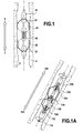
Fig. 1 is cross-sectional schematic view of an embodiment of the tool in accordance of the present invention showing the relative displacement of the first and second group of arms or extensions from the tool body. -
Fig. 1A is a cross-sectional schematic view of an alternative embodiment of the tool in accordance with the present invention showing an alternative displacement of the first and second group of arms or extensions from the tool body. -
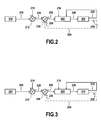
Fig. 2 is a schematic diagram of the controller actions of an embodiment of the present invention enabling logging upon egress from the wellbore. -
Fig. 3 is a schematic diagram of the controller actions of an embodiment of the present invention enabling logging upon ingressing the wellbore. - According to an aspect of the present invention, a method for regulating an arm of a wellbore tool comprises the steps of deploying a tool having a plurality of adjustable wellbore wall-engaging arms in a wellbore; sensing a wellbore physical characteristic at a leading portion of the tool in a direction of movement in the wellbore; and, controlling the adjustable wellbore wall-engaging arms utilizing the wellbore physical characteristic to regulate the position of the wall-engaging arms relative to the wellbore wall.
- This method can also be accomplished when the tool is deployed and sensing both upon ingress and upon egress from the wellbore, and permit sensing a wellbore physical characteristic such as sensing a plurality of distances between the tool and the wellbore wall. This method can also be practiced by controlling the tool by determining the change of the wellbore physical characteristic at the leading portion of the wall-engaging arms in the direction of movement in the wellbore.
- The wellbore tool comprises a tool body attached to a wellbore conveying means, said tool body having a first group of wall-engaging arms capable of determining a physical characteristic of the wellbore near the first group of wall-engaging arms, and a second group of wall-engaging arms capable of determining a differing physical characteristic of the wellbore near the second group of wall-engaging arms, and a control device utilizing the measured physical characteristic of the wellbore from the first group of wall-engaging arms to regulate the deployment of the second group of wall-engaging arms relative to the wellbore wall; the method further comprising the steps of deploying the wellbore tool in a direction of movement in the wellbore; sensing a physical characteristic of the wellbore near the first group of wall-engaging arms; and, controlling the second group of wall-engaging arms utilizing the measured physical characteristic of the wellbore near the first group of wall-engaging arms to regulate the position of the second group of wall-engaging arms relative to the wellbore wall.
- A method for regulating an arm of a wellbore tool comprising the steps of deploying a tool having a plurality of adjustable wellbore wall-engaging arms in a wellbore; providing a plurality of wellbore physical characteristics to a control device of the tool; and, controlling the adjustable wellbore wall-engaging arms utilizing at least a portion of the plurality of wellbore physical characteristics to regulate the position of the wall-engaging arms relative to the wellbore wall. The method can further allow the plurality of wellbore physical characteristics be derived from a prior measurement of wellbore physical characteristics; and, again, providing measurement with the tool both upon ingress and upon egress from the wellbore. The method permits a plurality of wellbore physical characteristics to be captured, and can include a plurality of widths of the wellbore wall at a plurality of depths. This novel apparatus permits controlled bidirectional movement of an oilfield tool within a wellbore is assembled from a tool body deployed in a wellbore permitting longitudinal movement of the tool in the wellbore; a first group of one or more wellbore wall-engaging arms attached to a circumferential surface of the tool body providing sensors for measuring one or more physical characteristics of the wellbore; a second group of one or more wellbore wall-engaging arms attached to the circumferential surface of the tool body providing sensors for measuring one or more physical characteristics of the wellbore; and, a controller connected to the first group and the second group of wall-engaging arms using a signal from the sensors of the first group of wall-engaging arms to regulate the position of the second group of wall-engaging arms relative to the wellbore wall.
- The deployment of the tool is accomplished in a wellbore by connecting the tool to a conveying mode selected from a group consisting of a drill string, a production string, a coil tubing string, a tool tractor, and a wireline. Moreover, the apparatus can be assembled with the first group and the second group of wall-engaging arms which can provide a sensing device selected from a group consisting of a pad tool, a caliper tool, a sensing tool, and a placement tool; and can provide an assembly wherein each pad tool is capable of providing a signal to activate an arm controlling mechanism.
- This apparatus can also utilize an arm controlling mechanisms selected from a group consisting of a piston, a screw, a sliding link, a spring, electric motor and a hydraulic pressure actuator, to accomplish the same purpose. The apparatus can provide a control function wherein the first group and the second group of wall-engaging arms are urged into continuous engagement with the wellbore wall; or, the apparatus can be deployed to engage the sensors of the second group of wall-engaging arms to obtain a signal used by the controller to modify the position of the first group of wall-engaging arms upon ingress of the wellbore; or, activate the sensors of the first group of wall-engaging arms to provide a signal used by the controller to modify the position of the second group of wall-engaging arms upon egress from the wellbore. This apparatus can additionally provide the means to position of the first group of wall-engaging arms at a predetermined stand-off position between the wellbore wall and a pad of each wall-engaging arm of the first group. Similarly, the apparatus can position the second group of wall-engaging arms at a predetermined stand-off position between the wellbore wall and a pad of each wall-engaging arm of the second group.
- As shown in
Fig. 1 , a regulation or control loop allowing logging or measuring or modification of the position of the arms or extensions of the sonde, ortool 10, is provided by a controller in or in communication with thetool 10 and permits logging in either or both directions for the tool with either pads or other sensing devices placed at the arm tip and in contact with the borehole surface. Close and continuous contact withwellbore 5 can be provided while preventing possible damage to the logging tool which can result from the failure to draw the arm(s) back into thetool body 10 when an obstruction or narrowing of thewellbore wall 4 is detected by the leading sensor, which can be eitherupper sensor 25, lower sensor 35 (depending on the direction of movement), or a sensor located on thetool body 10 above, or below, the arms (depending on the direction of longitudinal movement). - As further shown in
Fig. 1 , thetool 10 is deployed in thewellbore 5 connected to a conveying means (not shown) having both an upper arm set 20 (also referred to herein as a "first group of wall-engaging arms") and the lower arm set 30 (also referred to herein as a "second group of wall-engaging arms") engaging thewellbore wall 4. The term "wall-engaging," and variations thereof, as used herein with reference to the arms is meant to include both selective continuous engagement with the wellbore wall, as well as providing a fixed distance between the sensing device and the wellbore wall. The direction foringress 7 andegress 6 are shown inFig. 1 . When ingressing 7 thewellbore 5, lower arm set 30 carries asensor 35 which provides a signal to the controller in thetool 10 functionally detecting the condition, such as the multi-axial diameter of the wellbore, shape of the wellbore, or distances between the wellbore wall and the tool at/near thesensor 35, thereby permitting the following upper arm set 20 to be adjusted to move providing continuous osculation of thewellbore wall 4. Lower arm set 30, which can be resiliently moved against thewellbore wall 4 in a manner commonly used in this art area, reactively closes as it contacts obstructions near thewellbore wall 4 without damage to the tool. - Similarly, upon
egress 6 from thewellbore 5,upper arm set 20 provides asensor 25 signaling the controller to move the lower arm set 30 to again continuously osculate or alternatively move off of thewellbore wall 4 to avoid damage to the trailing arm set. Upper arm set 20, upon egress, reactively moves to close after contact upon encountering an obstruction inwellbore wall 4, again avoiding damage to the tool. -
Fig. 1A shows an alternative to existing arm or extension attachment designs more fully described in a companion application titled Method and Apparatus for Symmetrical Pad Connection on a Dual Articulated Arm Assembly Enhancing Pad Movement and Sustained Pad Contact with Borehole, which application is incorporated herein by reference as if fully copied herein. The optionalpassive protection arms 40 shown inFig. 1 provide an alternative means for implementation of the present invention, but are not required. The alternativepassive arms 40 can be affixed in an overlapping arrangement as shown inFig. 1A. Fig. 1A provides anupper group 104 of arms and pads affixed on a wellbore tool body and controlled byhydraulic means 100, which pushcalipers 102 outwardly to engage thewellbore 112. The lower arms of theupper group 104 are attached to the tool body at 114 and are interleaved with upper arms of alower group 106. Thelower group 106 of arms and pads may be moved byhydraulic means 110 acting oncalipers 108, and the interleaving provides an advantage of minimal separation between the upper pads and the lower pads. This also permits the apparatus to be engaged either when moving into thewellbore 122 or out of thewellbore 124. - The method of an embodiment of the present invention results from a measurement made previously by the conveyed tool or any other source of information (previous run, another tool in the toolstring) providing controlling feedback to adjust the position of a fragile tool section (such as the arm tool or the pad tool), or a tool section requiring a precise positioning with respect to the wellbore wall. The potentially fragile tool section can be damaged if no action of closing/protecting is taken prior to passing over the wellbore irregularity or diameter changes. The precise positioning tool section may require a certain stand-off distance (i.e., a spaced apart distance between the wellbore wall and a pad) rather than full engagement with the wellbore wall. Also, as is known by well logging practitioners, even momentary catches restraining the movement of the sensor arm set can distort measurement readings or cause skipping of the arm over portions of the
wellbore wall 4 inFig.1 . The method can be symbolized as a regulation or control loop, either open or closed, disclosed inFigs. 2 and 3 . - As shown in schematic representation of
Fig. 2 , the regulation or control of the disclosed apparatus starts with the methods described herein. Sensors disposed on an upper arm set can be described asSet 1 210 providing the input of the regulation or control system. Set 1 210 can consist of a single sensor or multiple sensors providing a matrix of input values for further processing by thecontroller 200. Moreover,Set 1 210 can be a device within the tool itself or represent input or signals derived from another source (e.g., different tool, previous logs). For a wellbore shape measurement, for example,Set 1 210 could be selected from any of the following types of sensors without departing from the spirit or intent of this disclosure: a caliper system, including multiarmed caliper tools; sonic tools; ultrasonic tools; or electromagnetic tools. - The data or signals detected schematically by
Set 1 210 are described asmeasurement 1 218, information given bySet 1 210. Typically, this measurement is borehole shape, including multi-axis diameters, but can be other measured physical characteristics as well. This system also provides the ability to compare the data fromactual measurement 218 withnominal values 214 inputted by the user of the system; such as expected measurement or average of previous measurements. These nominal conditions can be selected to describe correct tool operation or physical limits necessary for the tool operation. The combination of these two signals or data streams in addingpoint 212 results in variation ε1 224 constituting the difference betweenmeasurement 1 218 andnominal values 214. This value can be functionally proportional to wellbore diameter variation, for example, and without limitation. Accordingly,variation ε 1 224 can represent borehole washouts, formation collapse or unconsolidated wellbore wall, casing/tubing entry, drilling diameter change, diameter irregularity when drilling, rock layer change, faults, or a whole array of other physical characteristics in the wellbore. - User input parameters (UIP) 216 can be determined by the user of the system and may describe the operating or policy limits predetermined by the user or the logging controller. These limits can be established in terms of variation or sampling speed, typically multi-axis diameter variation within a defined distance, rugosity limits, hole shape variation (like ovalization) and the like.
Controller 200 utilizes the policy or operating parameters in a built-in interpretation device which, based onvariation ε 1 224 andUIP 216 will decide or indicate what protective/corrective action 226 (represented as a signal to the Set 2 220 sensors) should be taken.Controller 200 can be fabricated using existing technology such as digital computers or programmable logic controllers (PLC), all in a manner well known in this art. Protective/corrective action 226 is primarily focused on protecting the hardware of Set 2 220 from possible damage or minimizing the possibility of hanging the tool body 10 (as shown inFig. 1 ) in the wellbore on previously sensed obstructions. This action can be accomplished by generating a signal causing closure of the arms or extensions of the following arm set, retracting or covering of the sensor elements or any other action necessary to avoid possible damage to tool parts. - Set 2 220 is the recipient of the output of the regulation or control signals received from the
controller 200. This is a device or collection of sensors within the tool that need to be protected. The sensing elements of Set 2 220 can be similar or identical to those found inSet 1 210, offering the ability for this arrangement to be used both upon ingress and egress from the wellbore. A feedback signal may be used to (1) provide input to thecontroller 200 of measurement 2 222 to notify thecontroller 200 of the real position of Set 2 220 allowing thecontroller 200 to refine its protective/corrective action 226; or (2) to measure a variation ε2 229 (such as standoff distance), which can be used to modify the input to thecontroller 200 through thefeedback loop 228 into addingpoint 230 resulting in a modifiedvariation ε 3 232 providing input to thecontroller 200. Typically, thevariation ε 2 229 could be the distance between the sensing device of Set 2 220 and the borehole wall. This measurement would then be included in the regulation loop to modifyvariation ε 1 224. Therefore, in addition to the protective/corrective function, the controller can act to keep the device of Set 2 220 at a set distance from the formation (or in contact). This alternative closed loop regulation (marked in dashed-lines on the diagram) can therefore provide excellent sensing contact while protecting Set 2 220 from damage, or maintaining a fixed distance between the sensing device of Set 2 220 and the borehole wall. - As previously described, this method is the most flexible and provides the greatest versatility because the tool provides both symmetrical sensing and control between
Set 1 210 and Set 2 220; and, while permitting each device inSet 1 210 or Set 2 210 to be selectively operational in a typical unidirectional manner - either up or down - inside a wellbore, in the manner presently provided by most tools, whether arm, pad or position sensing technologies. - A possible configuration of the apparatus of this invention is a multi-arm tool with different closing directions for an upper arm set (Set 1) and a lower arm set (Set 2). When conveying upwards,
Set 1 will give the measurement 1 (i.e., four-axis borehole radius), which will be compared to the nominal wellbore diameter or shape adjusted by a correction factor (provided by previous measurements). The output of this comparison is a set of values (i.e., nominal distance differences ε1 224). Considering that Set 2 220 is currently logging wellbore characteristics while also sensing and recording data from its contact with the formation (i.e., when ε2=0), the controller 200 (in thetool body 10 or in communication therewith as shown inFig. 1 ) analyzes both the variations ofε 1 224 and deviations fromUIP 216. If the user limit is exceeded (i.e. wellbore shape variation higher than set value per foot), the protective/corrective action 226 of closing the arm of Set 2 220 begins. While closing the arms, standoff measurements (ε2) 229 are evaluated (i.e., from a pad measurement) and the controller can initiate an adjustment by reopening or reclosing the arms. Contact of the sensing device with the wellbore for improved logging can therefore be achieved while avoiding damage. As soon as variations ε1 224 and a measurement 2 222 orε 2 229 dip below the user-set limits of theUIP 216, the protective/corrective actions stop, since the Set 2 contact is within the appropriate limits with no risk of damage to the arm or the tool body. - When conveying upon ingress or downwards, the opposite steps occur as Set 2 220 provides the measurement providing input for the regulation of
Set 1 210 as on the following or trailing arm set. As more fully shown inFig. 3 , the logging device equipped or enabled by this invention allows logging, measuring, or moving indifferent to the direction of movement of the tool in the wellbore. While logging upon ingress, lower arm set 30 (as shown inFig. 1 ) senses wellbore wall obstructions and other physical conditions such as the diameter at Set 2 220. A signal or measurement 2 222 is sent to thecontroller 200 after comparison withnominal values 214 previously loaded in the apparatus as described above.Variation ε 2 228 is calculated at addingpoint 212 providing input to thecontroller 200. Serious deviations, as determined from thepolicy parameters UIP 216 inserted by the user allow the calculation providing protective/corrective actions 226 for use by theSet 1device 210 moving or adjusting the arm or extension controlled. As before,Set 1 210 can provide a feedback signal that can be used to (1) provide input to thecontroller 200 ofmeasurement 1 218 to notify thecontroller 200 of the real position ofSet 1 210 allowing thecontroller 200 to refine its protective/corrective action 226; or (2) to measure a variation ε1 225 (such as standoff distance), which can be used to modify the input to thecontroller 200 through thefeedback loop 224 into addingpoint 230 resulting in a modifiedvariation ε 3 232 providing input to thecontroller 200. The device can be equipped, for example, with pads or sensing devices placed at the arm tip and in contact with the wellbore wall surface. In addition, enhanced contact with the wellbore wall while preventing possible damage can be provided with this second form of regulation, orfeedback loop 224 upon ingress of the tool. Thus, the method provides a means of measurement of wellbore wall conditions and adjustment of the logging arms or extensions to avoid damage to the sensors, maintain a portion of the tool in a fixed distance from the wellbore wall, or prevent sticking of the tool on both ingress and egress of the tool from the wellbore. - Normal tool conveyance speed when logging is usually around 1800 ft/hr (15 cm/sec.) The distance between the two sets of arms (the upper 20 and the lower 30 in
Fig. 1 ) of between 50 cm to 1 m creates a reaction time of at least 3 seconds for the protective/corrective action. The protective/corrective action could also be linked with a warning or a decrease in the conveying speed, allowing a longer time for the regulation process to take effect. - Numerous other embodiments and alternatives thereof have been disclosed. While the above disclosure includes the best mode for carrying out the invention as contemplated by the named inventors, not all possible alternatives have been disclosed. For that reason, the scope and limitation of the present invention is not to be restricted to the above disclosure, but is instead to be defined and construed by the appended claims.
Claims (18)
- A method for regulating an arm of a wellbore tool (10) comprising the steps of:deploying a tool (10) having a plurality of adjustable wellbore wall-engaging arms (20, 30, 104, 106) in a wellbore (5, 112);sensing a wellbore physical characteristic at a leading portion of the tool (10) in a direction of movement in the wellbore (5, 112); and,controlling the adjustable wellbore wall-engaging arms (20, 30, 104, 106) utilizing the wellbore physical characteristic to regulate the position of the wall-engaging arms (20, 30, 104, 106) relative to the wellbore wall (4).
- The method of claim 1 wherein the tool (10) is capable of deploying and sensing both upon ingress (7, 122) and upon egress (6, 124) from the wellbore (5, 112).
- The method of any of the preceding claims wherein sensing a wellbore physical characteristic includes sensing a plurality of distances between the tool (10) and the wellbore wall (4).
- The method of any of the preceding claims wherein the controlling is provided by determining the change of the wellbore physical characteristic at the leading portion of the wall-engaging arms (20, 30, 104, 106) in the direction of movement in the wellbore (5, 112).
- The method of any of the preceding claims wherein the wellbore tool (10) comprises a tool body (10) attached to a wellbore conveying means, said tool body (10) having a first group of wall-engaging arms (20, 104) capable of determining a physical characteristic of the wellbore (5, 112) near the first group of wall-engaging arms (20, 104), and a second group of wall-engaging arms (30, 106) capable of determining a differing physical characteristic of the wellbore (5, 112) near the second group of wall-engaging arms (30, 106), and a control device utilizing the measured physical characteristic of the wellbore (5, 112) from the first group of wall-engaging arms (20, 104) to regulate the deployment of the second group of wall-engaging arms (30, 106) relative to the wellbore wall (4);
the method further comprising the steps of:deploying the wellbore tool (10) in a direction of movement in the wellbore (5, 112);sensing a physical characteristic of the wellbore (5, 112) near the first group of wall-engaging arms (20, 104); and,controlling the second group of wall-engaging arms (30, 106) utilizing the measured physical characteristic of the wellbore (5, 112) near the first group of wall-engaging arms (20, 104) to regulate the position of the second group of wall-engaging arms (30, 106) relative to the wellbore wall (4). - A method for regulating an arm of a wellbore tool (10) comprising the steps of:deploying a tool (10) having a plurality of adjustable wellbore wall-engaging arms (20, 30, 104, 106) in a wellbore (5, 112);providing a plurality of wellbore physical characteristics to a control device of the tool (10); and,controlling the adjustable wellbore wall-engaging arms (20, 30, 104, 106) utilizing at least a portion of the plurality of wellbore physical characteristics to regulate the position of the wall-engaging arms (20, 30, 104, 106) relative to the wellbore wall (4).
- The method of claim 6 wherein the plurality of wellbore physical characteristics is provided by a prior measurement of wellbore physical characteristics.
- The method of claim 6 or 7 wherein the tool (10) is capable of deploying both upon ingress (7, 122) and upon egress (6, 124) from the wellbore (5, 112).
- The method of any of claims 6-8 wherein the plurality of wellbore physical characteristics includes a plurality of widths of the wellbore wall (4) at a plurality of depths.
- An apparatus permitting controlled bidirectional movement of an oilfield tool within a wellbore (5, 112) comprising:a tool body (10) deployed in a wellbore (5, 112) permitting longitudinal movement of the tool (10) in the wellbore (5, 112);a first group of one or more wellbore wall-engaging arms (20, 104) attached to a circumferential surface of the tool body (10) providing sensors (25) for measuring one or more physical characteristics of the wellbore (5, 112);a second group of one or more wellbore wall-engaging arms (30, 106) attached to the circumferential surface of the tool body (10) providing sensors (35) for measuring one or more physical characteristics of the wellbore (5, 112); and,a controller (200) connected to the first group and the second group of wall-engaging arms (20, 30, 104, 106) using a signal from the sensors (25) of the first group of wall-engaging arms (20, 104) to regulate the position of the second group of wall-engaging arms (30, 106) relative to the wellbore wall (4).
- The apparatus of claim 10 wherein the deployment of the tool (10) is accomplished in a wellbore (5, 112) by connecting the tool (10) to a conveying mode selected from a group consisting of a drill string, a production string, a coil tubing string, a tool tractor, and a wireline.
- The apparatus of claim 10 or 11 wherein the first group and the second group of wall-engaging arms (20, 30, 104, 106) provide a sensing device (25, 35) selected from a group consisting of a pad tool, a caliper tool, a sensing tool, and a placement tool; wherein each pad tool is capable of providing a signal to activate an arm controlling mechanism.
- The apparatus of claim 12 wherein the arm controlling mechanism is selected from a group consisting of a piston, a screw, a sliding link, a spring, electric motor and a hydraulic pressure actuator.
- The apparatus of any of claims 10-13 wherein the first group and the second group of wall-engaging arms (20, 30, 104, 106) are urged into continuous engagement with the wellbore wall (4).
- The apparatus of any of claims 10-14 wherein the sensors (35) of the second group of wall-engaging arms (30, 106) provide a signal used by the controller (200) to modify the position of the first group of wall-engaging arms (20, 104) upon ingress (7, 122) of the wellbore (5, 112).
- The apparatus of any of claims 10-15 wherein the sensors (25) of the first group of wall-engaging arms (20, 104) provide a signal used by the controller (200) to modify the position of the second group of wall-engaging arms (30, 106) upon egress (6, 124) from the wellbore (5, 112).
- The apparatus of claim 15 wherein the position of the first group of wall-engaging arms (20, 104) is a predetermined stand-off position between the wellbore wall (4) and a pad of each wall-engaging arm of the first group.
- The apparatus of claim 16 wherein the position of the second group of wall-engaging arms (30, 106) is a predetermined stand-off position between the wellbore wall (4) and a pad of each wall-engaging arm of the second group.
Priority Applications (4)
| Application Number | Priority Date | Filing Date | Title |
|---|---|---|---|
| EP09290658A EP2290190A1 (en) | 2009-08-31 | 2009-08-31 | Method and apparatus for controlled bidirectional movement of an oilfield tool in a wellbore environment |
| MX2010009440A MX2010009440A (en) | 2009-08-31 | 2010-08-27 | Method and apparatus for controlled bidirectional movement of an oilfield tool in a wellbore environment. |
| US12/871,601 US8365822B2 (en) | 2009-08-31 | 2010-08-30 | Interleaved arm system for logging a wellbore and method for using same |
| US12/871,566 US8579037B2 (en) | 2009-08-31 | 2010-08-30 | Method and apparatus for controlled bidirectional movement of an oilfield tool in a wellbore environment |
Applications Claiming Priority (1)
| Application Number | Priority Date | Filing Date | Title |
|---|---|---|---|
| EP09290658A EP2290190A1 (en) | 2009-08-31 | 2009-08-31 | Method and apparatus for controlled bidirectional movement of an oilfield tool in a wellbore environment |
Publications (1)
| Publication Number | Publication Date |
|---|---|
| EP2290190A1 true EP2290190A1 (en) | 2011-03-02 |
Family
ID=41579973
Family Applications (1)
| Application Number | Title | Priority Date | Filing Date |
|---|---|---|---|
| EP09290658A Withdrawn EP2290190A1 (en) | 2009-08-31 | 2009-08-31 | Method and apparatus for controlled bidirectional movement of an oilfield tool in a wellbore environment |
Country Status (3)
| Country | Link |
|---|---|
| US (1) | US8579037B2 (en) |
| EP (1) | EP2290190A1 (en) |
| MX (1) | MX2010009440A (en) |
Cited By (2)
| Publication number | Priority date | Publication date | Assignee | Title |
|---|---|---|---|---|
| CN105673008A (en) * | 2016-02-29 | 2016-06-15 | 中国海洋石油总公司 | High-coverage-rate multi-arm sidewall contact device for slim hole |
| CN110678625A (en) * | 2017-04-17 | 2020-01-10 | 斯伦贝谢技术有限公司 | Self-retracting wall contacts logging sensor |
Families Citing this family (45)
| Publication number | Priority date | Publication date | Assignee | Title |
|---|---|---|---|---|
| US6464003B2 (en) | 2000-05-18 | 2002-10-15 | Western Well Tool, Inc. | Gripper assembly for downhole tractors |
| EP2290190A1 (en) * | 2009-08-31 | 2011-03-02 | Services Petroliers Schlumberger | Method and apparatus for controlled bidirectional movement of an oilfield tool in a wellbore environment |
| US8365822B2 (en) * | 2009-08-31 | 2013-02-05 | Schlumberger Technology Corporation | Interleaved arm system for logging a wellbore and method for using same |
| US8602115B2 (en) * | 2009-12-01 | 2013-12-10 | Schlumberger Technology Corporation | Grip enhanced tractoring |
| US8485253B2 (en) * | 2010-08-30 | 2013-07-16 | Schlumberger Technology Corporation | Anti-locking device for use with an arm system for logging a wellbore and method for using same |
| US8464791B2 (en) * | 2010-08-30 | 2013-06-18 | Schlumberger Technology Corporation | Arm system for logging a wellbore and method for using same |
| US9447648B2 (en) | 2011-10-28 | 2016-09-20 | Wwt North America Holdings, Inc | High expansion or dual link gripper |
| US9963954B2 (en) * | 2012-11-16 | 2018-05-08 | Saudi Arabian Oil Company | Caliper steerable tool for lateral sensing and accessing |
| AU2013385822B2 (en) | 2013-04-08 | 2017-03-30 | Halliburton Energy Services, Inc. | Protective sheath for logging tools |
| US9488020B2 (en) | 2014-01-27 | 2016-11-08 | Wwt North America Holdings, Inc. | Eccentric linkage gripper |
| US8851193B1 (en) | 2014-04-09 | 2014-10-07 | Cary A. Valerio | Self-centering downhole tool |
| US9777572B2 (en) | 2014-11-17 | 2017-10-03 | Baker Hughes Incorporated | Multi-probe reservoir sampling device |
| US9850724B2 (en) | 2015-04-02 | 2017-12-26 | Schlumberger Technology Corporation | Downhole tools and methods of controlling downhole tools |
| GB2530651B (en) * | 2015-08-19 | 2016-10-19 | Global Tech And Innovation Ltd | A downhole tractor |
| GB2578551B (en) | 2017-06-20 | 2022-07-13 | Sondex Wireline Ltd | Sensor deployment system and method |
| CA3067838C (en) | 2017-06-20 | 2021-11-16 | Sondex Wireline Limited | Sensor bracket system and method for a downhole tool |
| CA3067908C (en) | 2017-06-20 | 2022-05-17 | Sondex Wireline Limited | Arm deployment system and method |
| US10907467B2 (en) | 2017-06-20 | 2021-02-02 | Sondex Wireline Limited | Sensor deployment using a movable arm system and method |
| US20190063214A1 (en) * | 2017-08-22 | 2019-02-28 | Baker Hughes, A Ge Company, Llc | Wellbore tool positioning system and method |
| MX2020003072A (en) | 2017-10-31 | 2020-07-28 | Halliburton Energy Services Inc | Processing resistivity images in wells with oil based muds. |
| WO2019088998A1 (en) | 2017-10-31 | 2019-05-09 | Halliburton Energy Services, Inc. | Calculation of mud angle for imaging wells with oil based muds |
| WO2019088996A1 (en) | 2017-10-31 | 2019-05-09 | Halliburton Energy Services, Inc. | Software tuning of borehole imagers |
| US11377946B2 (en) | 2018-03-13 | 2022-07-05 | Halliburton Energy Services, Inc. | Borehole imaging tool |
| US11914097B2 (en) | 2018-03-29 | 2024-02-27 | Halliburton Energy Services, Inc. | Method for combined resistivity and permitivity determination with borehole imagers |
| US11442188B2 (en) | 2018-03-30 | 2022-09-13 | Halliburton Energy Services, Inc. | Dip detection in logging image processing |
| US11543555B2 (en) | 2018-04-11 | 2023-01-03 | Halliburton Energy Services, Inc. | Method to estimate formation resistivity |
| WO2019203791A1 (en) | 2018-04-16 | 2019-10-24 | Halliburton Energy Services, Inc. | Deconvolution-based enhancement of apparent resistivity and bed boundary identification in borehole resistivity imaging |
| US10970814B2 (en) | 2018-08-30 | 2021-04-06 | Halliburton Energy Services, Inc. | Subsurface formation imaging |
| US11249217B2 (en) | 2018-11-15 | 2022-02-15 | Halliburton Energy Services, Inc. | Method for resistivity determination with borehole imagers |
| WO2020139363A1 (en) | 2018-12-28 | 2020-07-02 | Halliburton Energy Services, Inc. | An electromagnetic insulating component used in well logging tool pad |
| US11836927B2 (en) | 2019-04-24 | 2023-12-05 | Halliburton Energy Services, Inc. | Borehole coring reconstructions using borehole scans |
| WO2020231411A1 (en) | 2019-05-14 | 2020-11-19 | Halliburton Energy Services, Inc. | System and method for measuring mud properties |
| US11442193B2 (en) * | 2019-05-17 | 2022-09-13 | Halliburton Energy Services, Inc. | Passive arm for bi-directional well logging instrument |
| US11365625B2 (en) | 2019-10-08 | 2022-06-21 | Halliburton Energy Services, Inc. | Determining broadband mud properties |
| US11746642B2 (en) | 2019-11-08 | 2023-09-05 | Halliburton Energy Services, Inc. | Electromagnetic imager design |
| CN110965993B (en) * | 2019-11-19 | 2023-01-10 | 中国石油天然气集团有限公司 | Push-leaning type three-arm temperature logging instrument |
| US11348218B2 (en) | 2020-03-30 | 2022-05-31 | Halliburton Energy Services, Inc. | Hybrid interpretation approach for borehole imaging |
| US11549358B2 (en) | 2020-10-22 | 2023-01-10 | Halliburton Energy Services, Inc. | Deep learning methods for enhancing borehole images |
| US12054999B2 (en) | 2021-03-01 | 2024-08-06 | Saudi Arabian Oil Company | Maintaining and inspecting a wellbore |
| US11448026B1 (en) | 2021-05-03 | 2022-09-20 | Saudi Arabian Oil Company | Cable head for a wireline tool |
| US11859815B2 (en) | 2021-05-18 | 2024-01-02 | Saudi Arabian Oil Company | Flare control at well sites |
| US11624263B2 (en) | 2021-05-25 | 2023-04-11 | Saudi Arabian Oil Company | Entering a lateral wellbore in a multi-lateral wellbore with a guide tool |
| US11905791B2 (en) | 2021-08-18 | 2024-02-20 | Saudi Arabian Oil Company | Float valve for drilling and workover operations |
| US11913298B2 (en) | 2021-10-25 | 2024-02-27 | Saudi Arabian Oil Company | Downhole milling system |
| US12276190B2 (en) | 2022-02-16 | 2025-04-15 | Saudi Arabian Oil Company | Ultrasonic flow check systems for wellbores |
Citations (11)
| Publication number | Priority date | Publication date | Assignee | Title |
|---|---|---|---|---|
| US4979585A (en) | 1989-10-02 | 1990-12-25 | Halliburton Logging Services, Inc. | Compound suspension linkage |
| WO1995021987A1 (en) * | 1994-02-14 | 1995-08-17 | Norsk Hydro A.S | Locomotive or tractor for pulling equipment in a pipe or drill hole |
| EP0911483A2 (en) * | 1997-10-27 | 1999-04-28 | Halliburton Energy Services, Inc. | Well system including composite pipes and a downhole propulsion system |
| US5947213A (en) | 1996-12-02 | 1999-09-07 | Intelligent Inspection Corporation | Downhole tools using artificial intelligence based control |
| US6112809A (en) | 1996-12-02 | 2000-09-05 | Intelligent Inspection Corporation | Downhole tools with a mobility device |
| WO2002037052A1 (en) * | 2000-11-01 | 2002-05-10 | Baker Hughes Incorporated | Use of magneto-resistive sensors for borehole logging |
| WO2002070943A2 (en) * | 2001-03-07 | 2002-09-12 | Carnegie Mellon University | Gas main robotic inspection system |
| EP1281834A1 (en) * | 2001-08-03 | 2003-02-05 | Schlumberger Technology B.V. | BI-Directional grip mechanism for a wide range of bore sizes |
| US6702010B2 (en) | 2001-02-15 | 2004-03-09 | Computalog Usa, Inc. | Apparatus and method for actuating arms |
| US7121364B2 (en) * | 2003-02-10 | 2006-10-17 | Western Well Tool, Inc. | Tractor with improved valve system |
| GB2459368A (en) * | 2008-04-23 | 2009-10-28 | Schlumberger Holdings | Tandem tractor assembly including multiple sondes |
Family Cites Families (36)
| Publication number | Priority date | Publication date | Assignee | Title |
|---|---|---|---|---|
| US2843459A (en) * | 1955-02-07 | 1958-07-15 | Bj Service Inc | Thermochemical logging tool |
| US3167707A (en) * | 1960-12-29 | 1965-01-26 | Seismograph Service Corp | Well logging apparatus having laterally shiftable wall engageable electrode supports |
| USRE32070E (en) * | 1961-08-31 | 1986-01-21 | Schlumberger Technology Corp. | Borehole apparatus for investigating subsurface earth formations including a plurality of pad members and means for regulating the bearing pressure thereof |
| FR1306134A (en) * | 1961-08-31 | 1962-10-13 | Schlumberger Prospection | Improvements to skid probes used in geophysics |
| FR1549531A (en) * | 1967-11-02 | 1968-12-13 | Schlumberger Prospection | |
| US4121345A (en) * | 1977-04-13 | 1978-10-24 | Dresser Industries, Inc. | Linearly corrected articulated linkage for wellbore measuring instrument |
| FR2512488A1 (en) * | 1981-09-09 | 1983-03-11 | Schlumberger Prospection | METHOD AND DEVICE FOR DIAGRAPHY USING A PROBE EQUIPPED WITH MEASURING SKATES |
| US4588951A (en) * | 1983-07-06 | 1986-05-13 | Schlumberger Technology Corporation | Arm apparatus for pad-type logging devices |
| US4757873A (en) * | 1986-11-25 | 1988-07-19 | Nl Industries, Inc. | Articulated transducer pad assembly for acoustic logging tool |
| US4857831A (en) * | 1986-12-29 | 1989-08-15 | Schlumberger Technology Corporation | Borehole casing diagnostic apparatus and method |
| FR2611919B1 (en) * | 1987-03-05 | 1989-06-16 | Schlumberger Prospection | LOGGING PROBE EQUIPPED WITH WIDE ANGLE OBSERVATION MEASURING PADS |
| US4926937A (en) * | 1989-06-08 | 1990-05-22 | Western Atlas International, Inc. | Compound linkage-arm assembly for use in bore-hole tools |
| US5092056A (en) * | 1989-09-08 | 1992-03-03 | Halliburton Logging Services, Inc. | Reversed leaf spring energizing system for wellbore caliper arms |
| BR9610373A (en) * | 1995-08-22 | 1999-12-21 | Western Well Toll Inc | Traction-thrust hole tool |
| US5794703A (en) * | 1996-07-03 | 1998-08-18 | Ctes, L.C. | Wellbore tractor and method of moving an item through a wellbore |
| DE69734917D1 (en) * | 1996-09-23 | 2006-01-26 | Halliburton Energy Serv Inc | INDEPENDENT DRILLING TOOL FOR THE PETROLEUM INDUSTRY |
| US6815954B2 (en) * | 2002-01-14 | 2004-11-09 | Computalog Usa, Inc. | Method and apparatus for full offset resistivity imaging for use in boreholes |
| US6843317B2 (en) * | 2002-01-22 | 2005-01-18 | Baker Hughes Incorporated | System and method for autonomously performing a downhole well operation |
| US6910533B2 (en) * | 2002-04-02 | 2005-06-28 | Schlumberger Technology Corporation | Mechanism that assists tractoring on uniform and non-uniform surfaces |
| GB0414672D0 (en) * | 2004-06-03 | 2004-08-04 | Pii Ltd | In-line pipe inspection tool |
| US7281578B2 (en) * | 2004-06-18 | 2007-10-16 | Schlumberger Technology Corporation | Apparatus and methods for positioning in a borehole |
| US7069775B2 (en) * | 2004-09-30 | 2006-07-04 | Schlumberger Technology Corporation | Borehole caliper tool using ultrasonic transducer |
| US7131210B2 (en) * | 2004-09-30 | 2006-11-07 | Schlumberger Technology Corporation | Borehole caliper tool |
| US7543512B2 (en) * | 2005-04-13 | 2009-06-09 | General Electric Company | Bore inspection probe |
| US7436185B2 (en) * | 2005-06-27 | 2008-10-14 | Schlumberger Technology Corporation | Highly integrated logging tool |
| US8863824B2 (en) * | 2006-02-09 | 2014-10-21 | Schlumberger Technology Corporation | Downhole sensor interface |
| US7543636B2 (en) * | 2006-10-06 | 2009-06-09 | Schlumberger Technology Corporation | Diagnostic sleeve shifting tool |
| GB2455685B (en) * | 2006-11-10 | 2011-03-23 | Rem Scient Entpr Inc | Rotating fluid measurement device and method |
| CA2669151C (en) * | 2006-11-14 | 2013-05-14 | Rudolph Ernst Krueger V | Variable linkage assisted gripper |
| US8484858B2 (en) * | 2009-06-17 | 2013-07-16 | Schlumberger Technology Corporation | Wall contact caliper instruments for use in a drill string |
| EP2290190A1 (en) * | 2009-08-31 | 2011-03-02 | Services Petroliers Schlumberger | Method and apparatus for controlled bidirectional movement of an oilfield tool in a wellbore environment |
| US8365822B2 (en) * | 2009-08-31 | 2013-02-05 | Schlumberger Technology Corporation | Interleaved arm system for logging a wellbore and method for using same |
| US7975541B2 (en) * | 2009-12-16 | 2011-07-12 | General Electric Company | Folding ultrasonic borehole imaging tool |
| US8464791B2 (en) * | 2010-08-30 | 2013-06-18 | Schlumberger Technology Corporation | Arm system for logging a wellbore and method for using same |
| US8485253B2 (en) * | 2010-08-30 | 2013-07-16 | Schlumberger Technology Corporation | Anti-locking device for use with an arm system for logging a wellbore and method for using same |
| US8468882B2 (en) * | 2010-11-30 | 2013-06-25 | Schlumberger Technology Corporation | Method and apparatus for logging a wellbore |
-
2009
- 2009-08-31 EP EP09290658A patent/EP2290190A1/en not_active Withdrawn
-
2010
- 2010-08-27 MX MX2010009440A patent/MX2010009440A/en active IP Right Grant
- 2010-08-30 US US12/871,566 patent/US8579037B2/en not_active Expired - Fee Related
Patent Citations (11)
| Publication number | Priority date | Publication date | Assignee | Title |
|---|---|---|---|---|
| US4979585A (en) | 1989-10-02 | 1990-12-25 | Halliburton Logging Services, Inc. | Compound suspension linkage |
| WO1995021987A1 (en) * | 1994-02-14 | 1995-08-17 | Norsk Hydro A.S | Locomotive or tractor for pulling equipment in a pipe or drill hole |
| US5947213A (en) | 1996-12-02 | 1999-09-07 | Intelligent Inspection Corporation | Downhole tools using artificial intelligence based control |
| US6112809A (en) | 1996-12-02 | 2000-09-05 | Intelligent Inspection Corporation | Downhole tools with a mobility device |
| EP0911483A2 (en) * | 1997-10-27 | 1999-04-28 | Halliburton Energy Services, Inc. | Well system including composite pipes and a downhole propulsion system |
| WO2002037052A1 (en) * | 2000-11-01 | 2002-05-10 | Baker Hughes Incorporated | Use of magneto-resistive sensors for borehole logging |
| US6702010B2 (en) | 2001-02-15 | 2004-03-09 | Computalog Usa, Inc. | Apparatus and method for actuating arms |
| WO2002070943A2 (en) * | 2001-03-07 | 2002-09-12 | Carnegie Mellon University | Gas main robotic inspection system |
| EP1281834A1 (en) * | 2001-08-03 | 2003-02-05 | Schlumberger Technology B.V. | BI-Directional grip mechanism for a wide range of bore sizes |
| US7121364B2 (en) * | 2003-02-10 | 2006-10-17 | Western Well Tool, Inc. | Tractor with improved valve system |
| GB2459368A (en) * | 2008-04-23 | 2009-10-28 | Schlumberger Holdings | Tandem tractor assembly including multiple sondes |
Cited By (4)
| Publication number | Priority date | Publication date | Assignee | Title |
|---|---|---|---|---|
| CN105673008A (en) * | 2016-02-29 | 2016-06-15 | 中国海洋石油总公司 | High-coverage-rate multi-arm sidewall contact device for slim hole |
| CN105673008B (en) * | 2016-02-29 | 2019-11-26 | 中国海洋石油集团有限公司 | A kind of slim-hole high coverage rate multi-arm telescoping ram |
| CN110678625A (en) * | 2017-04-17 | 2020-01-10 | 斯伦贝谢技术有限公司 | Self-retracting wall contacts logging sensor |
| CN110678625B (en) * | 2017-04-17 | 2023-10-27 | 斯伦贝谢技术有限公司 | Self-retracting wall contact logging sensor |
Also Published As
| Publication number | Publication date |
|---|---|
| US20110048801A1 (en) | 2011-03-03 |
| MX2010009440A (en) | 2011-08-05 |
| US8579037B2 (en) | 2013-11-12 |
Similar Documents
| Publication | Publication Date | Title |
|---|---|---|
| US8579037B2 (en) | Method and apparatus for controlled bidirectional movement of an oilfield tool in a wellbore environment | |
| MX2010010651A (en) | System and method for tracking origins of produce. | |
| US20170145760A1 (en) | Dynamically automated adjustable downhole conveyance technique for an interventional application | |
| US10309176B2 (en) | Pump down conveyance | |
| EP2867463B1 (en) | Lwd resistivity imaging tool with adjustable sensor pads | |
| US10495779B2 (en) | Downhole sensing cable system for improved seismic energy coupling to the cable system | |
| AU2012385499B2 (en) | A system and method for wireline tool pump-down operations | |
| CN101743376B (en) | A wired smart reamer | |
| EP3201435B1 (en) | Measurement method and system | |
| US20120241172A1 (en) | Pipe conveyed extendable well logging tool | |
| CA2918731C (en) | Estimation and calibration of downhole buckling conditions | |
| NO20190094A1 (en) | Downhole positioning control system with force compensation | |
| AU2015244221A1 (en) | Control systems and methods for centering a tool in a wellbore | |
| US9771788B2 (en) | Stiction control | |
| US20250327365A1 (en) | Non-contact gyroscopic centralizer tools and methods of use |
Legal Events
| Date | Code | Title | Description |
|---|---|---|---|
| PUAI | Public reference made under article 153(3) epc to a published international application that has entered the european phase |
Free format text: ORIGINAL CODE: 0009012 |
|
| AK | Designated contracting states |
Kind code of ref document: A1 Designated state(s): AT BE BG CH CY CZ DE DK EE ES FI FR GB GR HR HU IE IS IT LI LT LU LV MC MK MT NL NO PL PT RO SE SI SK SM TR |
|
| AX | Request for extension of the european patent |
Extension state: AL BA RS |
|
| 17P | Request for examination filed |
Effective date: 20110615 |
|
| 17Q | First examination report despatched |
Effective date: 20110728 |
|
| STAA | Information on the status of an ep patent application or granted ep patent |
Free format text: STATUS: THE APPLICATION IS DEEMED TO BE WITHDRAWN |
|
| 18D | Application deemed to be withdrawn |
Effective date: 20170425 |