EP2289735A1 - Improved locking mechanism - Google Patents
Improved locking mechanism Download PDFInfo
- Publication number
- EP2289735A1 EP2289735A1 EP10173912A EP10173912A EP2289735A1 EP 2289735 A1 EP2289735 A1 EP 2289735A1 EP 10173912 A EP10173912 A EP 10173912A EP 10173912 A EP10173912 A EP 10173912A EP 2289735 A1 EP2289735 A1 EP 2289735A1
- Authority
- EP
- European Patent Office
- Prior art keywords
- support member
- locking
- slide
- assembly
- support
- Prior art date
- Legal status (The legal status is an assumption and is not a legal conclusion. Google has not performed a legal analysis and makes no representation as to the accuracy of the status listed.)
- Withdrawn
Links
- 230000007246 mechanism Effects 0.000 title description 13
- 125000006850 spacer group Chemical group 0.000 claims description 9
- 229920003023 plastic Polymers 0.000 claims description 5
- 239000004033 plastic Substances 0.000 claims description 5
- 239000000463 material Substances 0.000 description 5
- 229910000831 Steel Inorganic materials 0.000 description 2
- 230000000712 assembly Effects 0.000 description 2
- 238000000429 assembly Methods 0.000 description 2
- 239000010959 steel Substances 0.000 description 2
- 230000000977 initiatory effect Effects 0.000 description 1
- 238000012423 maintenance Methods 0.000 description 1
- 239000002184 metal Substances 0.000 description 1
Images




Classifications
-
- B—PERFORMING OPERATIONS; TRANSPORTING
- B60—VEHICLES IN GENERAL
- B60P—VEHICLES ADAPTED FOR LOAD TRANSPORTATION OR TO TRANSPORT, TO CARRY, OR TO COMPRISE SPECIAL LOADS OR OBJECTS
- B60P3/00—Vehicles adapted to transport, to carry or to comprise special loads or objects
- B60P3/32—Vehicles adapted to transport, to carry or to comprise special loads or objects comprising living accommodation for people, e.g. caravans, camping, or like vehicles
- B60P3/34—Vehicles adapted to transport, to carry or to comprise special loads or objects comprising living accommodation for people, e.g. caravans, camping, or like vehicles the living accommodation being expansible, collapsible or capable of rearrangement
Definitions
- the present invention relates to locking support assemblies, and in particular to locking hydraulic support assemblies for use with slide-out sides in vehicles and trailers and the like.
- Another way which has been proposed of locking the side walls is a hydraulic clamp which clamps over the front ends of support beams, clamping the support beam so that the beam, and thus the slide out side, cannot be moved when the slide out side is in the stowed position.
- the hydraulic clamp When unstowing the sliding side wall the hydraulic clamp is first operated to release the clamp and then the full hydraulic system can be operated to move the slide out side into the position.
- the problem with this form of locking mechanism is that the locking mechanism is hidden behind the slide-out sides and the locking mechanism is difficult to get to for maintenance or fault solving when the slide-out side is stuck or locked in the stowed position.
- a locking support assembly for a slide-out side of a vehicle or trailer comprising: a support arm assembly adapted to support the slide-out side comprising:
- This arrangement is particularly advantageous as not only is the locking mechanism located lower down so that there is adequate space for provision of windows in the side walls of the slide-out side, but also the locking mechanism, being located at the rear of the support assembly is easy to get to and not hidden behind panelling when the slide-out side is in the stowed position.
- the locking support assembly further comprises a hydraulic arm assembly adapted to move the slide-out side from a stowed position to an unstowed position and from the unstowed position to the stowed position in conjunction with the second support member.
- a hydraulic arm assembly adapted to move the slide-out side from a stowed position to an unstowed position and from the unstowed position to the stowed position in conjunction with the second support member.
- the first support member comprises a first beam and wherein the second support member comprises a second beam.
- the locking assembly comprises a first jaw and a second jaw.
- first and second jaws are adapted to open on contact with the locking pin when the slide-out side is being moved from an unstowed position to a stowed position.
- first and second jaws are plates adapted to close around and engage the locking pin.
- the locking assembly further comprises an actuator adapted to open the first and second jaws and disengage the locking pin when the slide-out side is being moved from a stowed position to an unstowed position.
- the locking pin is mounted vertically and the jaws of the locking assembly are mounted horizontally.
- the locking pin is mounted externally to the second support member.
- the locking assembly is mounted externally to the first support member.
- the second support member is adapted to move with respect to the first support member using bearings.
- the bearings are plastic bearings.
- the second support member is located inside the first support member.
- the second support member is provided with a means to prevent horizontal movement of the second support member within the first support member.
- the means to prevent horizontal movement of the second support member within the first support member are spacer elements extending from the outside of the second support member towards the inside of the first member at the first end and the second end.
- a locking support assembly for a slide-out side of a vehicle or trailer comprising: a support arm assembly adapted to support the slide-out side comprising:
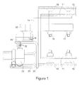
- FIG. 1 this illustrates a side cross-section view of the rear section of the support member of the support assembly.
- the support assembly is made up of a first support member or outer beam 10 made of rectangular box-section steel and a second support member or inner beam 11 again made of rectangular box-section steel.
- the inner beam 11 is of smaller cross-section than the outer beam 10.
- the inner beam 11 is located inside the outer beam 10.
- bearings 12, 13 made of a plastics material.
- the bearings 12, 13 are made of a metal or any other suitable material.
- the bearings 12, 13 allow for smooth running of the inner beam 11 inside the outer beam 10.
- the bearings 12, 13 run the full length of the outer beam 10.
- the bearings 12, 13 are fixed to the inside surface of the outer beam 10.
- the bearings 12, 13 are fixed to the outside surface of the Inner beam 11.
- the second beam or support member is not internal to the first beam or support member but instead runs along the upper outer surface of the first beam or support member.
- a bracket assembly 14, 15 is fixed to the inner beam 11 with nuts and bolts 16, 17.
- a locking pin 18 is fixed to the bracket assembly 14, 15.
- the bracket assembly 14, 15 is constructed such that the locking pin 18 extends vertically downwardly as shown from the second inner beam 11.
- the bracket assembly 14, 15 is also constructed such that the locking pin 18 extends outside of the second inner beam 11.
- a locking mechanism 19 comprises jaws (not shown) which are adapted to open when pressure is applied from one direction, i.e. from direction unstowed to stowed, by the locking pin 18 and close around the locking pin 18.
- the jaws are adapted not to open when pressure is applied from the opposite direction, i.e. from direction stowed to unstowed. The jaws will only open in that direction when opened with an actuator.
- the locking mechanism 19 is fixed to a bracket assembly 20.
- the bracket assembly 20 is fixed to outer beam 10.
- the locking pin 18 and locking mechanism 19 are arranged such that they are located central to the internal horizontal and vertical axis of the inner beam 11.
- the locking mechanism 19 is connected to an actuator 21, and a lever 22 connects the locking mechanism 19 and the actuator 21.
- the actuator 21 is electrically operated. In an alternative it may be hydraulically operated. When operated, the actuator 21 moves the lever 22, opening the jaws (not shown) of the locking mechanism, releasing the locking pin 18.
- the actuator 21 is connected to a bracket 23 which is connected to bracket 20, which is connected to the outer beam 10.
- Figure 2 and Figure 2a illustrate a rear cross-section view of the same portion of the support arm assembly of Figure 1 .
- the bearings 12 (not shown) 13 are provide with cheeks 30, 31.
- the cheeks 30,31 act to prevent lateral movement of the inner beam 11 within the outer beam 10 at the rear of the support assembly. This is particularly important as the inner beam 11 extends out of the outer beam 10 as the slide out side is being moved from a stowed position to an un-stowed position.
- the cheeks 30,31 are preferably formed from the same material as the bearing 13, which is preferably a plastics material.
- FIGS 5 and 6 illustrate an alternative horizontal mounting of locking pin 18 within the inner beam 11.
- the locking pin 18 is mounted horizontally but extends outside by use of a bracket as in Figures 1 to 4 .
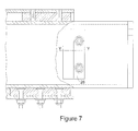
- FIGS 7 and 8 these illustrate spacer elements 25, 26 extending horizontally from the inner beam 11 at the first front end of the beam.
- the spacer elements 25, 26 prevent lateral movement of the inner beam 11 within the outer beam 10.
- Similar spacer elements may in addition be located at the second rear end of the beam in an alternative to the cheeks 30, 31 extending from bearing 13 as discussed above.
- the spacer elements extend from the outside edge of the inner beam 11 to the internal edge of the outer beam 10.
- the spacer elements are formed from a plastics material.
- the inner beam 11 is provided with a front end plate 27 which is fixed to the front outside wall of the slide-out side so that as the slide-out side moves from the stowed position to the unstowed position under hydraulic action the underside of the slide-out side rests upon the inner beam 11.
Landscapes
- Engineering & Computer Science (AREA)
- Health & Medical Sciences (AREA)
- Public Health (AREA)
- Transportation (AREA)
- Mechanical Engineering (AREA)
- Body Structure For Vehicles (AREA)
Abstract
A locking support assembly for a slide-out side of a vehicle or trailer comprising: a support arm assembly adapted to support the slide-out side comprising:
i) a first support member (10) having a first end and a second end, the first support member being connected to the vehicle or trailer such that the first end is located proximal to the side of the vehicle with the slide-out side and the second end is located remote from the side of the vehicle with the slide-out side;
ii) a second support member (11) having a first end and a second end, the second support member being connected to the slide-out side such that the first end is located proximal to the side of the vehicle with the slide-out side and the second end is located remote from the side of the vehicle with the slide-out side when the slide-out side is in a stowed position;
the second support member (11) being movable with respect to the first support member (10) to support the slide-out side when the slide-out side is being moved from the stowed position to an unstowed position and from the unstowed position to the stowed position;
wherein the second end of the first support member (10) is provided with a locking assembly (19) and the second end of the second support member is provided with a locking pin (18), the locking pin (18) being adapted to engage with the locking assembly (19) when the slide-out side is in the stowed position.
i) a first support member (10) having a first end and a second end, the first support member being connected to the vehicle or trailer such that the first end is located proximal to the side of the vehicle with the slide-out side and the second end is located remote from the side of the vehicle with the slide-out side;
ii) a second support member (11) having a first end and a second end, the second support member being connected to the slide-out side such that the first end is located proximal to the side of the vehicle with the slide-out side and the second end is located remote from the side of the vehicle with the slide-out side when the slide-out side is in a stowed position;
the second support member (11) being movable with respect to the first support member (10) to support the slide-out side when the slide-out side is being moved from the stowed position to an unstowed position and from the unstowed position to the stowed position;
wherein the second end of the first support member (10) is provided with a locking assembly (19) and the second end of the second support member is provided with a locking pin (18), the locking pin (18) being adapted to engage with the locking assembly (19) when the slide-out side is in the stowed position.
Description
- The present invention relates to locking support assemblies, and in particular to locking hydraulic support assemblies for use with slide-out sides in vehicles and trailers and the like.
- It has become increasingly commonplace for many road-going vehicles such as RV's horseboxes, caravans, trailers and the like to be fitted with slide-out sides. In essence, a portion of the side of the vehicle is adapted to slide out creating additional space inside the vehicle. A true side is fixed whereas a slide-out-side moves between 2 or more positions. Typically the side of the vehicle slides out between 0.5 and 1 metre, supported on beams and is operated using hydraulic systems. The width of a vehicle is restricted for normal legal road use, but extra space inside the vehicle is desired for people spending large amounts of time in their vehicles, hence slide-out sides. The slide-out sides are stowed away whilst on the road to comply with legal width requirements. The sides of the vehicle also need to be locked in the stowed position when on the road.
- One way which has been proposed of locking the sides of the vehicle in the stowed position is a locking hook and pin system located in the upper sides of the slide-out sides. The problem with this is that the locking mechanisms take up so much space that it is not possible to put windows or the like into the sidewalls of the side out sides.
- Another way which has been proposed of locking the side walls is a hydraulic clamp which clamps over the front ends of support beams, clamping the support beam so that the beam, and thus the slide out side, cannot be moved when the slide out side is in the stowed position. When unstowing the sliding side wall the hydraulic clamp is first operated to release the clamp and then the full hydraulic system can be operated to move the slide out side into the position. The problem with this form of locking mechanism is that the locking mechanism is hidden behind the slide-out sides and the locking mechanism is difficult to get to for maintenance or fault solving when the slide-out side is stuck or locked in the stowed position.
- According to a first aspect of the present invention, there is provided a locking support assembly for a slide-out side of a vehicle or trailer comprising: a support arm assembly adapted to support the slide-out side comprising:
- i) a first support member having a first end and a second end, the first support member being connected to the vehicle or trailer such that the first end is located proximal to the side of the vehicle with the slide-out side and the second end is located remote from the side of the vehicle with the slide-out side;
- ii) a second support member having a first end and a second end, the second support member being connected to the slide-out side such that the first end is located proximal to the side of the vehicle with the slide-out side and the second end is located remote from the side of the vehicle with the slide-out side when the slide-out side is in a stowed position;
- This arrangement is particularly advantageous as not only is the locking mechanism located lower down so that there is adequate space for provision of windows in the side walls of the slide-out side, but also the locking mechanism, being located at the rear of the support assembly is easy to get to and not hidden behind panelling when the slide-out side is in the stowed position.
- Preferably the locking support assembly further comprises a hydraulic arm assembly adapted to move the slide-out side from a stowed position to an unstowed position and from the unstowed position to the stowed position in conjunction with the second support member. This is advantageous as the slide-out side is moved from the stowed position to the unstowed position automatically on initiation of the hydraulic arm assembly.
- Preferably the first support member comprises a first beam and wherein the second support member comprises a second beam.
- Preferably the locking assembly comprises a first jaw and a second jaw.
- Preferably the first and second jaws are adapted to open on contact with the locking pin when the slide-out side is being moved from an unstowed position to a stowed position.
- Preferably the first and second jaws are plates adapted to close around and engage the locking pin.
- Preferably the locking assembly further comprises an actuator adapted to open the first and second jaws and disengage the locking pin when the slide-out side is being moved from a stowed position to an unstowed position.
- Preferably the locking pin is mounted vertically and the jaws of the locking assembly are mounted horizontally.
- Preferably the locking pin is mounted externally to the second support member.
- Preferably the locking assembly is mounted externally to the first support member.
- Preferably the second support member is adapted to move with respect to the first support member using bearings.
- Preferably the bearings are plastic bearings.
- Preferably the second support member is located inside the first support member.
- Preferably the second support member is provided with a means to prevent horizontal movement of the second support member within the first support member.
- Preferably the means to prevent horizontal movement of the second support member within the first support member are spacer elements extending from the outside of the second support member towards the inside of the first member at the first end and the second end.
- According to a second aspect of the present invention there is provided a vehicle or trailer comprising a locking support assembly for a slide-out side of a vehicle or trailer comprising: a support arm assembly adapted to support the slide-out side comprising:
- i i) a first support member having a first end and a second end, the first support member being connected to the vehicle or trailer such that the first end is located proximal to the side of the vehicle with the slide-out side and the second end is located remote from the side of the vehicle with the slide-out side;
- ii) a second support member having a first end and a second end, the second support member being connected to the slide-out side such that the first end is located proximal to the side of the vehicle with the slide-out side and the second end is located remote from the side of the vehicle with the slide-out side when the slide-out side is in a stowed position;
- Other aspects and features of the present invention will become apparent to those ordinarily skilled in the art upon review of the following description of specific embodiments of the invention in conjunction with the accompanying figures.
- The invention will now be described, by way of example only, with reference to the accompanying which of which:
-
Figure 1 is a side cross-section view of the rear section of the support member of the support assembly showing the locking assembly; -
Figure 2 is a rear cross-section view of the rear section of the support member of the support assembly ofFigure 1 showing the locking assembly; -
Figure 2a is a scrap cross-section of line X-X inFigure 2 ; -
Figure 3 is a side partial cross-section view of an alternative embodiment of the rear section of the support member of the support assembly; -
Figure 3a is a scrap cross-section of line X-X inFigure 3 ; -
Figure 4 is a rear cross-section view of an alternative embodiment of the rear section of the support assembly ofFigure 3 ; -
Figure 5 is a side cross-section view of an alternative embodiment of the rear section of the support member of the support assembly; -
Figure 6 is a rear cross-section view of an alternative embodiment of the rear section of the support member of the support assembly ofFigure 5 ; -
Figure 7 is a side partial cross-section view of the front section of the support member of the support assembly Illustrating the spacer elements; -
Figure 8 is a partial cross-section view of the front section of the support member of the support assembly illustrating the spacer elements ofFigure 7 ; -
Figure 9 is a side view of the full support member of the support assembly; -
Figure 10 is a top view of the full support member of the support assembly ofFigure 9 : -
Figure 11 is a front view of the support member of the support assembly ofFigures 9 and 10 ; -
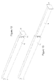
Figure 12 Is a perspective view of the support member of the support assembly in a stowed position; and -
Figure 13 is a perspective view of the support member of the support assembly in an un-stowed position. - Referring to
Figure 1 , this illustrates a side cross-section view of the rear section of the support member of the support assembly. The support assembly is made up of a first support member orouter beam 10 made of rectangular box-section steel and a second support member orinner beam 11 again made of rectangular box-section steel. Theinner beam 11 is of smaller cross-section than theouter beam 10. Theinner beam 11 is located inside theouter beam 10. In between theouter beam 10 and theinner beam 11 are locatedbearings bearings bearings inner beam 11 inside theouter beam 10. Thebearings outer beam 10. Thebearings outer beam 10. In an alternative thebearings Inner beam 11. In a further alternative the second beam or support member is not internal to the first beam or support member but instead runs along the upper outer surface of the first beam or support member. - A
bracket assembly inner beam 11 with nuts andbolts pin 18 is fixed to thebracket assembly bracket assembly pin 18 extends vertically downwardly as shown from the secondinner beam 11. Thebracket assembly pin 18 extends outside of the secondinner beam 11. Alocking mechanism 19 comprises jaws (not shown) which are adapted to open when pressure is applied from one direction, i.e. from direction unstowed to stowed, by the lockingpin 18 and close around the lockingpin 18. The jaws are adapted not to open when pressure is applied from the opposite direction, i.e. from direction stowed to unstowed. The jaws will only open in that direction when opened with an actuator. Thelocking mechanism 19 is fixed to abracket assembly 20. Thebracket assembly 20 is fixed toouter beam 10. The lockingpin 18 andlocking mechanism 19 are arranged such that they are located central to the internal horizontal and vertical axis of theinner beam 11. Thelocking mechanism 19 is connected to anactuator 21, and alever 22 connects thelocking mechanism 19 and theactuator 21. Theactuator 21 is electrically operated. In an alternative it may be hydraulically operated. When operated, theactuator 21 moves thelever 22, opening the jaws (not shown) of the locking mechanism, releasing the lockingpin 18. Theactuator 21 is connected to abracket 23 which is connected tobracket 20, which is connected to theouter beam 10. -
Figure 2 and Figure 2a illustrate a rear cross-section view of the same portion of the support arm assembly ofFigure 1 . It is dear fromFigure 2 and Figure 2a that the bearings 12 (not shown) 13 are provide withcheeks cheeks inner beam 11 within theouter beam 10 at the rear of the support assembly. This is particularly important as theinner beam 11 extends out of theouter beam 10 as the slide out side is being moved from a stowed position to an un-stowed position. Thecheeks bearing 13, which is preferably a plastics material. - Referring to
Figures 3 and4 , these illustrate analternative bracket arrangement 24 for lockingpin 18. - Referring to
Figures 5 and 6 , these illustrate an alternative horizontal mounting of lockingpin 18 within theinner beam 11. In a further alternative (not shown) thelocking pin 18 is mounted horizontally but extends outside by use of a bracket as inFigures 1 to 4 . - Referring to
Figures 7 and8 , these illustratespacer elements inner beam 11 at the first front end of the beam. Thespacer elements inner beam 11 within theouter beam 10. Similar spacer elements may in addition be located at the second rear end of the beam in an alternative to thecheeks inner beam 11 to the internal edge of theouter beam 10. The spacer elements are formed from a plastics material. - Referring to
Figures 9, 10, 11 ,12 and 13 these illustrate the full length ofouter beam 10 andinner beam 11. - The
inner beam 11 is provided with afront end plate 27 which is fixed to the front outside wall of the slide-out side so that as the slide-out side moves from the stowed position to the unstowed position under hydraulic action the underside of the slide-out side rests upon theinner beam 11.
wherein the second end of the first support member is provided with a locking assembly and the second end of the second support member is provided with a locking pin, the locking pin being adapted to engage with the locking assembly when the slide-out side is in the stowed position.
wherein the second end of the first support member is provided with a locking assembly and the second end of the second support member is provided with a locking pin, the locking pin being adapted to engage with the locking assembly when the slide-out side is in the stowed position.
Claims (15)
- A locking support assembly for a slide-out side of a vehicle or trailer comprising:a support arm assembly adapted to support the slide-out side comprising:i) a first support member having a first end and a second end, the first support member being connected to the vehicle or trailer such that the first end is located proximal to the side of the vehicle with the slide-out side and the second end is located remote from the side of the vehicle with the slide-out side;ii) a second support member having a first end and a second end, the second support member being connected to the slide-out side such that the first end is located proximal to the side of the vehicle with the slide-out side and the second end is located remote from the side of the vehicle with the slide-out side when the slide-out side is in a stowed position;the second support member being movable with respect to the first support member to support the slide-out side when the slide-out side is being moved from the stowed position to an unstowed position and from the unstowed position to the stowed position;
wherein the second end of the first support member is provided with a locking assembly and the second end of the second support member is provided with a locking pin, the locking pin being adapted to engage with the locking assembly when the slide-out side is in the stowed position. - A locking support assembly as claimed in claim 1, wherein the locking support assembly further comprising a hydraulic arm assembly adapted to move the slide-out side from a stowed position to an unstowed position and from the unstowed position to the stowed position in conjunction with the second support member.
- A locking support assembly as claimed in claim 1 or claim 2, wherein the first support member comprises a first beam and wherein the second support member comprises a second beam.
- A locking support assembly as claimed in any preceding claim, wherein the locking assembly comprises a first jaw and a second jaw.
- A locking support assembly as claimed in claim 4, wherein the first and second jaws are adapted to open on contact with the locking pin when the slide-out side is being moved from an unstowed position to a stowed position.
- A locking support assembly as claimed in claim 5, wherein the first and second jaws are plates adapted to close around and engage the locking pin.
- A locking support assembly as claimed in any of claims 4 to 6 wherein the locking assembly further comprises an actuator adapted to open the first and second jaws and disengage the locking pin when the slide-out side is being moved from a stowed position to an unstowed position.
- A locking support assembly as claimed in any preceding claim, wherein the locking pin is mounted vertically and the jaws of the locking assembly are mounted horizontally.
- A locking support assembly as claimed in any preceding claim, wherein the locking pin is mounted externally to the second support member.
- A locking support assembly as claimed in any preceding claim wherein the locking assembly is mounted externally to the first support member.
- A locking support assembly as claimed in any preceding claim, wherein the second support member is adapted to move with respect to the first support member using bearings.
- A locking support assembly as claimed in claim 11, wherein the bearings are plastic bearings.
- A locking support assembly as claimed in any preceding claim, wherein the second support member is located inside the first support member.
- A locking support assembly as claimed in claim 13, wherein the second support member is provided with a means to prevent horizontal movement of the second support member within the first support member.
- A locking support assembly as claimed in claim 14, wherein the means to prevent horizontal movement of the second support member within the first support member are spacer elements extending from the outside of the second support member towards the inside of the first member at the first end and the second end.
Applications Claiming Priority (1)
| Application Number | Priority Date | Filing Date | Title |
|---|---|---|---|
| GBGB0914741.4A GB0914741D0 (en) | 2009-08-24 | 2009-08-24 | Locking support assembly |
Publications (1)
| Publication Number | Publication Date |
|---|---|
| EP2289735A1 true EP2289735A1 (en) | 2011-03-02 |
Family
ID=41171814
Family Applications (1)
| Application Number | Title | Priority Date | Filing Date |
|---|---|---|---|
| EP10173912A Withdrawn EP2289735A1 (en) | 2009-08-24 | 2010-08-24 | Improved locking mechanism |
Country Status (2)
| Country | Link |
|---|---|
| EP (1) | EP2289735A1 (en) |
| GB (2) | GB0914741D0 (en) |
Citations (6)
| Publication number | Priority date | Publication date | Assignee | Title |
|---|---|---|---|---|
| FR2360444A1 (en) * | 1976-01-22 | 1978-03-03 | Riout Roland | Extendable mobile caravan assembly - has two half-bodies which slide laterally on roller supports from main body almost doubling its width |
| US5560444A (en) * | 1995-06-30 | 1996-10-01 | Hydra-Slide Corporation | Expandable trailer having a position locking feature |
| US5785373A (en) * | 1995-12-28 | 1998-07-28 | Winnebago Industries | Recreational vehicle with slide-out room |
| US6007142A (en) * | 1997-07-03 | 1999-12-28 | Fleetwood Folding Trailers, Inc. | Folding trailer with extendable room |
| US6094870A (en) * | 1998-05-26 | 2000-08-01 | Qc Metal Fab, Inc. | Locking device for slide-out rooms |
| US20080290689A1 (en) * | 2001-11-15 | 2008-11-27 | Norco Industries, Inc. | Slidable room support system |
Family Cites Families (2)
| Publication number | Priority date | Publication date | Assignee | Title |
|---|---|---|---|---|
| US6257638B1 (en) * | 1998-09-16 | 2001-07-10 | K-Z, Inc. | Travel trailer with rear wall slide-out room |
| CA2337719A1 (en) * | 2000-03-10 | 2001-09-10 | Prevost Car Inc. | Locking pin system |
-
2009
- 2009-08-24 GB GBGB0914741.4A patent/GB0914741D0/en not_active Ceased
-
2010
- 2010-08-24 GB GB1014111A patent/GB2473120A/en not_active Withdrawn
- 2010-08-24 EP EP10173912A patent/EP2289735A1/en not_active Withdrawn
Patent Citations (6)
| Publication number | Priority date | Publication date | Assignee | Title |
|---|---|---|---|---|
| FR2360444A1 (en) * | 1976-01-22 | 1978-03-03 | Riout Roland | Extendable mobile caravan assembly - has two half-bodies which slide laterally on roller supports from main body almost doubling its width |
| US5560444A (en) * | 1995-06-30 | 1996-10-01 | Hydra-Slide Corporation | Expandable trailer having a position locking feature |
| US5785373A (en) * | 1995-12-28 | 1998-07-28 | Winnebago Industries | Recreational vehicle with slide-out room |
| US6007142A (en) * | 1997-07-03 | 1999-12-28 | Fleetwood Folding Trailers, Inc. | Folding trailer with extendable room |
| US6094870A (en) * | 1998-05-26 | 2000-08-01 | Qc Metal Fab, Inc. | Locking device for slide-out rooms |
| US20080290689A1 (en) * | 2001-11-15 | 2008-11-27 | Norco Industries, Inc. | Slidable room support system |
Also Published As
| Publication number | Publication date |
|---|---|
| GB2473120A (en) | 2011-03-02 |
| GB0914741D0 (en) | 2009-09-30 |
| GB201014111D0 (en) | 2010-10-06 |
Similar Documents
| Publication | Publication Date | Title |
|---|---|---|
| CN102910209B (en) | Activity engine closure assembly for vehicle | |
| US5906387A (en) | Retractable hitch for a gooseneck trailer | |
| US9656702B2 (en) | Fifth wheel hitch support assembly | |
| US10800339B2 (en) | Vehicle rack assembly and rack accessing method | |
| EP0683271A1 (en) | Post arrangement | |
| US20230150585A1 (en) | Truck Bedslide Assembly | |
| CN102431607A (en) | Lifting clamping device for car door conveying line | |
| US20080265625A1 (en) | Truck Comprising a Rope-Operated Tilting Device for the Cab | |
| US7726678B1 (en) | Sliding fifth wheel assembly | |
| US11230335B2 (en) | Solar panel rack, motor vehicle roof rail | |
| US11292701B2 (en) | Vehicle mounted hoist | |
| US20110089711A1 (en) | Tailgate Lowering Apparatus and Method | |
| US20040256874A1 (en) | Recreational vehicle with side out members | |
| CA2717122C (en) | Sliding hitch assembly | |
| EP2289735A1 (en) | Improved locking mechanism | |
| CA2661076C (en) | Mechanical tailgate | |
| US11560046B1 (en) | School bus emergency egress system | |
| CN116279941B (en) | A manual dump engineering vehicle | |
| CA2503572C (en) | Retractable tail-lift with carriage guidance | |
| DE102005062279A1 (en) | Motor vehicle with braking installation having self-enclosed braking cushion on vehicle floor which expands in active state to brake and has control device partly or wholly inside to activate it | |
| EP4227155A1 (en) | Construction vehicle with a base vehicle and a body | |
| JP3803542B2 (en) | Rear bumper device in a vehicle with a cargo receiving platform lifting device | |
| JP3838621B2 (en) | Rear bumper device in a vehicle with a cargo receiving platform lifting device | |
| JP5017056B2 (en) | Loading platform lifting device | |
| JP3235238U (en) | Loading device for freight vehicles |
Legal Events
| Date | Code | Title | Description |
|---|---|---|---|
| PUAI | Public reference made under article 153(3) epc to a published international application that has entered the european phase |
Free format text: ORIGINAL CODE: 0009012 |
|
| AK | Designated contracting states |
Kind code of ref document: A1 Designated state(s): AL AT BE BG CH CY CZ DE DK EE ES FI FR GB GR HR HU IE IS IT LI LT LU LV MC MK MT NL NO PL PT RO SE SI SK SM TR |
|
| AX | Request for extension of the european patent |
Extension state: BA ME RS |
|
| 17P | Request for examination filed |
Effective date: 20110902 |
|
| STAA | Information on the status of an ep patent application or granted ep patent |
Free format text: STATUS: THE APPLICATION IS DEEMED TO BE WITHDRAWN |
|
| 18D | Application deemed to be withdrawn |
Effective date: 20140301 |