EP2289140B1 - System and method for efficient association of a power outlet and device - Google Patents
System and method for efficient association of a power outlet and device Download PDFInfo
- Publication number
- EP2289140B1 EP2289140B1 EP08743412.2A EP08743412A EP2289140B1 EP 2289140 B1 EP2289140 B1 EP 2289140B1 EP 08743412 A EP08743412 A EP 08743412A EP 2289140 B1 EP2289140 B1 EP 2289140B1
- Authority
- EP
- European Patent Office
- Prior art keywords
- power
- distribution unit
- power distribution
- cable
- outlet
- Prior art date
- Legal status (The legal status is an assumption and is not a legal conclusion. Google has not performed a legal analysis and makes no representation as to the accuracy of the status listed.)
- Active
Links
Images




Classifications
-
- G—PHYSICS
- G06—COMPUTING OR CALCULATING; COUNTING
- G06F—ELECTRIC DIGITAL DATA PROCESSING
- G06F1/00—Details not covered by groups G06F3/00 - G06F13/00 and G06F21/00
- G06F1/26—Power supply means, e.g. regulation thereof
- G06F1/266—Arrangements to supply power to external peripherals either directly from the computer or under computer control, e.g. supply of power through the communication port, computer controlled power-strips
-
- G—PHYSICS
- G06—COMPUTING OR CALCULATING; COUNTING
- G06F—ELECTRIC DIGITAL DATA PROCESSING
- G06F2200/00—Indexing scheme relating to G06F1/04 - G06F1/32
- G06F2200/26—Indexing scheme relating to G06F1/26
- G06F2200/261—PC controlled powerstrip
-
- Y—GENERAL TAGGING OF NEW TECHNOLOGICAL DEVELOPMENTS; GENERAL TAGGING OF CROSS-SECTIONAL TECHNOLOGIES SPANNING OVER SEVERAL SECTIONS OF THE IPC; TECHNICAL SUBJECTS COVERED BY FORMER USPC CROSS-REFERENCE ART COLLECTIONS [XRACs] AND DIGESTS
- Y02—TECHNOLOGIES OR APPLICATIONS FOR MITIGATION OR ADAPTATION AGAINST CLIMATE CHANGE
- Y02D—CLIMATE CHANGE MITIGATION TECHNOLOGIES IN INFORMATION AND COMMUNICATION TECHNOLOGIES [ICT], I.E. INFORMATION AND COMMUNICATION TECHNOLOGIES AIMING AT THE REDUCTION OF THEIR OWN ENERGY USE
- Y02D10/00—Energy efficient computing, e.g. low power processors, power management or thermal management
Definitions
- This invention relates generally to power distribution devices, such as, power strips, and more particularly to power distribution units having certain intelligent capabilities.
- Intelligent power distribution devices offer enhanced power distribution and monitoring capabilities for certain sensitive electrical and electronic applications.
- An exemplary application where deployment of intelligent power distribution devices has proven useful is in the powering of multiple computer servers that are involved in the provision of network services.
- the ability to control and monitor power distribution can prove to be an invaluable tool for computer network operators and IT personnel.
- the Dominion PX IPDU offers increased operational and monitoring capabilities at each of the AC power outlets included in the device. Generally, these capabilities will include the ability to turn an outlet on and off, and also provide power consumption measurements for that outlet, among other features. In order for these capabilities to be at all useful, it is necessary for the intelligent power device or equipment monitoring the intelligent power device to know what specific equipment is at the other end of a power cable plugged into each outlet of the intelligent power device.
- US 2007/273208 discloses an automatic sensing power system which automatically determines a power requirement for an electrical device.
- An advance is made over the prior art in accordance with the principles of the present invention that is directed to a system and method for providing automatic or semi-automatic identity association between an outlet of an intelligent power distribution unit and a target device, such as a computer server, which is powered by that outlet.
- the association is accomplished by enabling identification information to be transmitted between an identification device near or within the target device and the intelligent power distribution unit via a power cable.
- the power cable may include a specialized interface for mating with the power distribution unit and/or providing the identification information.
- a target device is supplied power from a specific outlet of an intelligent power distribution unit.
- the system contains an identification device proximate the target device for receiving identification information from the target. Further, the cable for supplying power between the target device and the intelligent power distribution unit enables communication of identification information between the identification device and the intelligent power distribution unit.
- a system for automatically associating an electrical device with a electrical outlet.
- the system contains an identification generating circuit for producing at least one signal used to uniquely identify the electrical device.
- the system further contains a first identification signal transceiver located proximate the electrical device and electrically connected to the identification generating circuit, and a second identification signal transceiver located proximate to and associated with the electrical outlet.
- a communications channel is disposed between the first identification signal transceiver and said second identification signal transceiver and is used to pass signals between the transceivers.
- the present invention discloses a system and method for providing automatic or semi-automatic identity association between an outlet of an intelligent power distribution unit and a target device, such as a computer server, which is powered by that outlet.
- a system 10 for enabling substantially automatic identity association between an intelligent power distribution unit 12 and a target device 14, where the target device is an electrical device includes or utilizes a power supply 16 that is powered by the intelligent power distribution unit 12.
- the system 10 includes a specialized power cable 20 for providing AC power and current from an outlet of the power distribution unit (PDU) 12.
- the power cable 20 includes at least two power conductors for providing AC power and may or may not include a separate ground conductor depending on the power system and the country in which the system is utilized.
- the standard power connections of the power cable mate between the power distribution unit and the target device in a known manner.
- the specialized power cable 20 includes two additional conductors, e.g., a data conductor 22 and ground 24 (sometimes referred to collectively as data conductors), for enabling identity data to be transmitted between the power distribution unit and target device.
- a data conductor 22 and ground 24 sometimes referred to collectively as data conductors
- the shown embodiment is illustrated as including two additional conductors, another possible configuration includes a single data conductor, where the single data line makes use of the AC ground for its reference. Such a configuration may not be eligible, however, for approval by certification agencies or other approval agencies in a number of regions. Additional data and/or power conductors may also be included as part of the specialized power cord.
- the data conductor 22 of the power cable couples on the power distribution unit side to a controller 26 within the power distribution unit 12.
- the data conductors 22, 24 of the specialized power cable 20 couple to the power distribution unit 12 by way of connections which are made, for example, through a latch unit 30 on the power distribution unit 12 and a corresponding latch plate receiving section on the collar of the power cable 20. In this way, standard methodologies of making power connections between the power distribution unit and target device are kept intact, e.g., standard two and three prong connectors.
- the latch unit 30 and coupling mechanism to the power cable are designed in order to keep the data conductors isolated from one another. Specific embodiments of coupling mechanisms between the power cable and the power distribution unit are described in greater detail herein. Various other designs of locking and latching mechanisms that provide coupling (and isolation) of the data conductors to the power distribution unit may also be utilized. Besides utilization of locking mechanisms, other means of securely coupling the data conductors to the power distribution unit may also be utilized.
- the data conductors 22, 24 couple to an identification (ID) device 40.
- ID identification
- ROM Read-Only Memory
- Exemplary devices of this type are memory devices from Maxim Integrated Products of Sunnyvale, CA (formerly Dallas Semiconductor) that utilize the 1-Wire® protocol.
- the 1-Wire protocol uses a signaling scheme that performs half-duplex bidirectional communications between a host/master controller and one or more slaves sharing a common data line. Both power and data communication for slave devices are transmitted over this single line. For power delivery, slaves capture charge on an internal capacitor when the line is in a high state and then use this charge for device operation when the line is low during data transmission.
- the ID device 40 forms part of the identification generating circuit and is attachable to or is in an area near the target device 14 and its power input, where the ID device is powered through the data conductors as described above.
- the ID device 40 is programmed to provide the power distribution unit 12, via a communications channel, such as the data conductors 22, 24, with a machine readable identification, for example a unique address number, for the target device 14.
- the ID device 40 is attached to the data conductors of the power cable 20, wherein the data conductors pigtail off of the power cable at the target end of the cable so as to enable a desired placement of the ID device in the vicinity of the target device.
- the data lines of the power cord terminate by way of a standardized connector, where the connector is made to mate with a corresponding connector on the ID device.
- ID devices can remain with the corresponding target equipment and programming of an ID device need only be accomplished once.
- the ID devices can be replaceable if desired, in the case of equipment failure at either the target or ID device itself.
- the server identification tags could also be in the form of Radio Frequency Identification (“RFID”) tags, where information from the RFID tags may be obtained via an RFID reader.
- RFID Radio Frequency Identification
- the RFID reader could be incorporated into the ID Device 40 or could be a separate device with an interface to the ID Device similar to the barcode reader.
- the ID Device 40 would couple externally (and perhaps temporarily) to the target device 14 through a cable, for example, a USB cable.
- a software application would be loaded on the target device which automatically loads identification information from the target device to the ID Device when prompted.
- the software application could be loaded to the target device along with other applications at configuration time or by way of a virtual media link or other like download, where KVM (keyboard-video-mouse) type equipment would have access to the target devices to enable the software download.
- KVM keyboard-video-mouse
- an additional useful functionality of a visual indicator is included in combination with the power cable 20 as shown.
- An LED 60 is placed on the target device end of the cable, ideally around the collar 62 of the power connector for maximum visibility. This LED 60 is powered and controlled by the data lines, and may provide (a) a useful indicator of whether power is enabled to the device, and (b) a marker for devices that are targeted for maintenance, to allow a repair technician to positively identify the device.
- An LED controller 64 for example, DS2413, manufactured by Dallas Semiconductor/Maxim Integrated Products, may be suitable for controlling one or more LEDs via the data lines.
- An LED device capable of producing multiple colors indicative of differing status conditions may also be utilized in connection with the LED controller.
- the LED may be manually operated by way of a button or other type switch which is included on one or both sides of the power cable.
- a visual indication regarding a specific power cable under deployment may be readily available to a technician.
- Such a feature would be advantageous when attempting to locate a specific cable among a large number of other like cables.
- Other types of indications for example, audible indications, are also possible in connection with the present invention and the disclosed architecture.
- the intelligent power distribution unit can distinguish between (a) disconnection of the ID device, and (b) complete disconnection of the cord lock/lwire bus. Having the ability to report this level of device connection status is extremely useful when attempting to report and resolve connection failures in an intelligent manner.
- monitoring of the ID devices 40 once association to a target device is made, enables the intelligent power distribution device to:
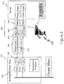
- FIG. 2 another embodiment for improved association between a power distribution unit 212 and a target device 214 is described.
- the same basic configuration of equipment is utilized for the power distribution unit 212, power cable 220 and ID device receiver 240.
- the power distribution unit 212 distributes a unique identity of the power distribution device and the power outlet to the ID receiver device 240 at the target device 214 or server.
- the association is then done in a portable device like a barcode scanner 250. That is, the power distribution unit 212, e.g., power strip, communicates a value associated with its ID and the ID of the outlet over the power cable 220, where it is placed into readable form at the end of the cable, for example, in the ID device receiver 240.
- the distribution of addresses from the power distribution unit can be based, for example, on information that is provided to the PDUs from a management system.
- detailed custom identification information (as opposed to more simple address information) could also be loaded to the ID devices based on that information being cascaded from the management system to the PDUs and then to the ID devices.
- Another alternative is that a default set of addresses is always provided from the PDU to corresponding ID devices and therefore, the association mechanism need also keep track of the specific PDU identification, e.g., a PDU number, in order to make a proper association.
- an individual After connecting the power cord to an outlet of the power distribution unit in order to download identification information to the ID devices, an individual uses the barcode scanner 250 (or similarly functioning device) to scan the server's barcode (or other like pertinent information), and then "reads" the end of each power cable to create an association inside the barcode scanner.
- the association information is uploaded to a management system 270 or database, either in real time if there is an active connection between the detecting device and the management system or at a later time when such a connection can be made. Since the flow of information to the ID receiver device is unidirectional, devices utilizing a bidirectional communication protocol need not be utilized, as would be understood by those skilled in the art.
- FIG. 3 there is shown another exemplary embodiment of a system 300 and method for improved association between an intelligent power distribution unit 312 and a target device 314.
- the system 300 of Fig. 3 makes use of an ID device 340 that is coupled to the power cable 320 and is located proximate the target device 314.
- the embodiment of Fig. 3 differs, however, in that communication between the intelligent power distribution unit 312 and ID device 340 takes place via the actual power conductors 322 of the power cable 320.
- each outlet on the power strip has the ability to communicate through its corresponding socket over the power conductors 322.
- a filter 330 is installed "behind" the power line communications interface 332 to keep each communication link isolated from each other (rather than colliding on the power main).
- the power line communications interface 332 enables data to be received over the power line connection and input to the management processor 328 of the intelligent power distribution unit. This can be accomplished, for example, through the use of a power line modem or other like device that provides isolation from the power system and enables a digital data protocol to be received at the management processor.
- An example of a suitable power line communications interface can be found in the PlugLink product line from Asoka USA Corporation.
- a complementary interface 342 is provided as part of a pass-through device 344 for each power input of a device, where, as would be understood, many devices support multiple power inputs, either for load sharing or for redundancy purposes.
- An ID device 340 or other like memory component within the pass-through device 344 is programmed with the server identification information (and perhaps the power input number) by way of an input device 350, such as a bar code scanner, as described with respect to Fig. 1 .
- the power distribution unit 312 queries the ID device 340 at the target device 314, and obtains the server identification.
- the outlet identification and the target device identification are both known by the outlet strip. The association may be kept internal to the strip or forwarded to a centralized management system.
- the power distribution unit 312 can also push its identification information over to the ID device 340 as described with respect to Fig. 2 .
- An association between the server information and the information captured from the ID device would then be made via a handheld device as previously described.
- the association information as captured by the device would then be downloaded or transferred for use by a management system.
- FIG. 4 another alternate embodiment of the present invention is shown.
- power line communications is again employed to transmit target identifying information to the power distribution unit 412, across a standard power cord 412.
- the power line interface 432 is similar to the interface described with respect to Fig. 3 .
- a complementary power line interface 442 is provided within the server or other target device 414 on each power input.
- Each interface includes memory and is provided with the server identification information, and the power input number from a location within the target device, for example, the Baseband Management Controller 460.
- the server identification information would be embedded or stored within the power supply, if for example, these power supplies were not swappable at the target device.
- the power strip When power is turned on, the power strip queries the target device, and obtains the server identification from the interface 442 of the target device 414. At this point, the outlet identification and the target device identification are both known by the power distribution unit (e.g., outlet strip). As with certain other embodiments of the invention, the association may be kept internal to the strip or forwarded to a centralized management system.
- the power distribution unit e.g., outlet strip
- FIG. 5 in combination with Fig. 6 , there is shown one exemplary embodiment of a coupling mechanism 500 between the power cable 520 of the present invention and the power distribution unit 512 that is particularly applicable to the embodiments described with respect to Figs. 1 and 2 .
- a male connector 516 is shown having a conventional three prong arrangement that is insertable into a conventional 110V North American outlet 518.
- the power cable 520 in proximity to the male connector 516 includes a specialized collar 532 that is adapted to couple with a latch or lock mechanism 522 from the PDU.
- the power cable 520 of the present invention includes two sets of conductors, data conductors 530 and power conductors 524, each of which are separately contained in insulation.
- the data conductors terminate within a two sided disc housing 534 for containing two conductive discs 536, 538.
- Each of the data conductors 530 (e.g., data and ground) is electrically coupled to one of the conductive discs.
- the latch portion 522 of the coupling mechanism 500 includes two sets of opposing contacts 542 that slip over the insulated power cable 520 and which have a number of points 544 along the contacts 542 that electrically couple to the electrically conductive discs 536, 538 in order to electrically connect the data conductors 530 with the controller of the PDU 512.
- the data conductors of the latch mechanism 522 which couple with respective sets of contacts 542 are included within or connected to the latch so that the data conductor may electrically couple to the controller within the PDU 512.
- the latch mechanism 522 of the PDU has a pivot proximate its connection at the PDU. The pivot allows the latch to be maneuvered on and off of the collar 532 of the power cable 520 when the connector 516 of the power cable needs to be inserted or removed from a power receptacle of the PDU 512.
- the male connector 716 includes a specialized collar 732 that is adapted to couple with the latch or lock mechanism 730 from the PDU.
- the collar includes two separate slots 736, 738 having electrically conductive material surrounding at least portions thereof. The conductive material of the slots electrically couples to respective ones of the data conductors 722 that are included within the cable 720.
- the latch portion 730 of the coupling mechanism 700 includes a specialized connector 742 that is adapted to be received and couple with the corresponding slots 736, 738 of the power cable.
- the latch 730 includes a slotted opening 740 that fits over and maintains a force fit connection with the conductive material 742 found in the corresponding slots 736, 738 of the power cable collar.
- the latch has separate corresponding conductors 744, 746 that make contact with the conductive slots in a manner similar to that of an insulation displacement (IDC) connector.
- the conductors of the latch mechanism are included within or connected to the latch so that the data conductor may electrically couple to the controller within the PDU.
- the latch mechanism of the PDU has a pivot 750 proximate its connection at the PDU. The pivot 750 allows the latch to be maneuvered on and off of the collar 732 of the power cable when the connector 716 of the power cable needs to be inserted or removed from a power receptacle of the PDU.
- the power cable of the present invention having additional conductors for providing the identification information to the intelligent power distribution unit may couple to the power distribution unit in the power connector region using additional prongs that are insertable into an outlet region.
- additional prongs that are insertable into an outlet region.
- complimentary contacts or tabs may also be included in or around the power connector region in order to couple the additional conductors to the power distribution unit.
- a single wire interface is preferable in order to limit the number of conductors that must be present in the power cable, it would be understood that additional conductors may be utilized within the power cable in order to make use of conventional data transmission protocols.
- any element expressed as a means for performing a specified function is intended to encompass any way of performing that function including, for example, a) a combination of circuit elements which performs that function or b) software in any form, including, therefore, firmware, microcode or the like, combined with appropriate circuitry for executing that software to perform the function.
- the invention as defined by such claims resides in the fact that the functionalities provided by the various recited means are combined and brought together in the manner which the claims call for. Applicant thus regards any means which can provide those functionalities as equivalent as those shown herein. Many other modifications and applications of the principles of the invention will be apparent to those skilled in the art and are contemplated by the teachings herein. Accordingly, the scope of the invention is limited only by the claims.
Landscapes
- Engineering & Computer Science (AREA)
- General Engineering & Computer Science (AREA)
- Theoretical Computer Science (AREA)
- Computer Hardware Design (AREA)
- Physics & Mathematics (AREA)
- General Physics & Mathematics (AREA)
- Cable Transmission Systems, Equalization Of Radio And Reduction Of Echo (AREA)
- Power Sources (AREA)
- Remote Monitoring And Control Of Power-Distribution Networks (AREA)
Description
- This invention relates generally to power distribution devices, such as, power strips, and more particularly to power distribution units having certain intelligent capabilities.
- Intelligent power distribution devices offer enhanced power distribution and monitoring capabilities for certain sensitive electrical and electronic applications. An exemplary application where deployment of intelligent power distribution devices has proven useful is in the powering of multiple computer servers that are involved in the provision of network services. Here, the ability to control and monitor power distribution can prove to be an invaluable tool for computer network operators and IT personnel.
- One known intelligent power device of the above-described type is the Dominion PX Intelligent Power Distribution Unit (IPDU), developed and sold by Raritan Corp. of Somerset, New Jersey. The Dominion PX IPDU offers increased operational and monitoring capabilities at each of the AC power outlets included in the device. Generally, these capabilities will include the ability to turn an outlet on and off, and also provide power consumption measurements for that outlet, among other features. In order for these capabilities to be at all useful, it is necessary for the intelligent power device or equipment monitoring the intelligent power device to know what specific equipment is at the other end of a power cable plugged into each outlet of the intelligent power device.
- At present, the only way to determine what equipment is associated with specific outlets of an intelligent power distribution device is to have that information manually entered. Such a manual association process may be inconvenient, subject to error and require additional manual updates any time a configuration change takes place.
-
US 2007/273208 discloses an automatic sensing power system which automatically determines a power requirement for an electrical device. - An advance is made over the prior art in accordance with the principles of the present invention that is directed to a system and method for providing automatic or semi-automatic identity association between an outlet of an intelligent power distribution unit and a target device, such as a computer server, which is powered by that outlet. The association is accomplished by enabling identification information to be transmitted between an identification device near or within the target device and the intelligent power distribution unit via a power cable. The power cable may include a specialized interface for mating with the power distribution unit and/or providing the identification information.
- In one aspect of the present invention there is provided a system according to
claim 1. In another aspect of the present invention there is provided a method according to claim 8. - Further aspects of the invention are outlined in the dependent claims. Embodiments which do not fall within the scope of the claims do not describe part of the present invention.
- In one described arrangement, a target device is supplied power from a specific outlet of an intelligent power distribution unit. The system contains an identification device proximate the target device for receiving identification information from the target. Further, the cable for supplying power between the target device and the intelligent power distribution unit enables communication of identification information between the identification device and the intelligent power distribution unit.
- In another described arrangement, a system is disclosed for automatically associating an electrical device with a electrical outlet. Wherein, the system contains an identification generating circuit for producing at least one signal used to uniquely identify the electrical device. The system further contains a first identification signal transceiver located proximate the electrical device and electrically connected to the identification generating circuit, and a second identification signal transceiver located proximate to and associated with the electrical outlet. A communications channel is disposed between the first identification signal transceiver and said second identification signal transceiver and is used to pass signals between the transceivers.
- The teachings of the present invention can be readily understood by considering the following detailed description in conjunction with the accompanying drawings, in which:
-
FIG. 1 shows one exemplary embodiment of a system for providing reliable association information between a target device and intelligent power distribution unit; -
FIG. 2 shows another exemplary embodiment of a system for providing identification association between a target device and intelligent power distribution unit; -
FIGs. 3 and4 show alternative exemplary embodiments for associating a target device to an intelligent power distribution unit using power conductors of a power cable to provide communication; -
FIGs. 5 and6 show an exemplary illustration of a coupling mechanism between the intelligent power distribution unit and specialized power cable; -
FIG. 7 shows another exemplary embodiment of a coupling mechanism between the intelligent power distribution unit and specialized power cable according to the present invention. - Exemplary embodiments of the invention will now be described while referring to the figures, several of which may be simultaneously referred to during the course of the following description.
- The present invention discloses a system and method for providing automatic or semi-automatic identity association between an outlet of an intelligent power distribution unit and a target device, such as a computer server, which is powered by that outlet.
- Referring to
Fig. 1 , there is shown one exemplary embodiment of asystem 10 in accordance with the present invention for enabling substantially automatic identity association between an intelligentpower distribution unit 12 and atarget device 14, where the target device is an electrical device includes or utilizes apower supply 16 that is powered by the intelligentpower distribution unit 12. As shown, thesystem 10 includes aspecialized power cable 20 for providing AC power and current from an outlet of the power distribution unit (PDU) 12. As would be understood, thepower cable 20 includes at least two power conductors for providing AC power and may or may not include a separate ground conductor depending on the power system and the country in which the system is utilized. The standard power connections of the power cable mate between the power distribution unit and the target device in a known manner. - In addition to the power connection conductors described above, the
specialized power cable 20 includes two additional conductors, e.g., adata conductor 22 and ground 24 (sometimes referred to collectively as data conductors), for enabling identity data to be transmitted between the power distribution unit and target device. Although the shown embodiment is illustrated as including two additional conductors, another possible configuration includes a single data conductor, where the single data line makes use of the AC ground for its reference. Such a configuration may not be eligible, however, for approval by certification agencies or other approval agencies in a number of regions. Additional data and/or power conductors may also be included as part of the specialized power cord. - As shown, the
data conductor 22 of the power cable couples on the power distribution unit side to acontroller 26 within thepower distribution unit 12. Thecontroller 26, which acts as a transceiver to transmit and receive identification data fromDevice 14, in turn, couples to a management module orprocessor 28 within thepower distribution unit 12. In a unique feature of the present invention, thedata conductors specialized power cable 20 couple to thepower distribution unit 12 by way of connections which are made, for example, through alatch unit 30 on thepower distribution unit 12 and a corresponding latch plate receiving section on the collar of thepower cable 20. In this way, standard methodologies of making power connections between the power distribution unit and target device are kept intact, e.g., standard two and three prong connectors. Thelatch unit 30 and coupling mechanism to the power cable are designed in order to keep the data conductors isolated from one another. Specific embodiments of coupling mechanisms between the power cable and the power distribution unit are described in greater detail herein. Various other designs of locking and latching mechanisms that provide coupling (and isolation) of the data conductors to the power distribution unit may also be utilized. Besides utilization of locking mechanisms, other means of securely coupling the data conductors to the power distribution unit may also be utilized. - On the opposite side of the power cable, the
data conductors device 40. This would generally include a programmable memory component, such as a Read-Only Memory (ROM) or non-volatile RAM. Exemplary devices of this type are memory devices from Maxim Integrated Products of Sunnyvale, CA (formerly Dallas Semiconductor) that utilize the 1-Wire® protocol. The 1-Wire protocol uses a signaling scheme that performs half-duplex bidirectional communications between a host/master controller and one or more slaves sharing a common data line. Both power and data communication for slave devices are transmitted over this single line. For power delivery, slaves capture charge on an internal capacitor when the line is in a high state and then use this charge for device operation when the line is low during data transmission. TheID device 40 forms part of the identification generating circuit and is attachable to or is in an area near thetarget device 14 and its power input, where the ID device is powered through the data conductors as described above. TheID device 40 is programmed to provide thepower distribution unit 12, via a communications channel, such as thedata conductors target device 14. - The
ID Device 40 could be programmed by any method that would give it unique information about thetarget device 14 usable to identify the target device. In one embodiment of the invention, the programming of the ID device is accomplished by means of acustom barcode reader 50. Thebarcode reader 50 enables a technician at setup to read an associatedbar code 52 off of the server identification tag or asset management tag and transmit this barcode scan to the memory of theID device 40. The transfer of information between the barcode scanner and the ID device may be accomplished via wired or wireless interface in a known manner. The bar code of the server identification tag will typically include either asset management tag information or server serial number information or any other like information for uniquely identifying the computer server target devices. - In one embodiment of the invention, the
ID device 40 is attached to the data conductors of thepower cable 20, wherein the data conductors pigtail off of the power cable at the target end of the cable so as to enable a desired placement of the ID device in the vicinity of the target device. As would be understood, the data lines of the power cord terminate by way of a standardized connector, where the connector is made to mate with a corresponding connector on the ID device. In this way, ID devices can remain with the corresponding target equipment and programming of an ID device need only be accomplished once. In addition, the ID devices can be replaceable if desired, in the case of equipment failure at either the target or ID device itself. As an alternative method of programming theID Device 40, the server identification tags could also be in the form of Radio Frequency Identification ("RFID") tags, where information from the RFID tags may be obtained via an RFID reader. The RFID reader could be incorporated into theID Device 40 or could be a separate device with an interface to the ID Device similar to the barcode reader. As a further alternative, theID Device 40 would couple externally (and perhaps temporarily) to thetarget device 14 through a cable, for example, a USB cable. A software application would be loaded on the target device which automatically loads identification information from the target device to the ID Device when prompted. The software application could be loaded to the target device along with other applications at configuration time or by way of a virtual media link or other like download, where KVM (keyboard-video-mouse) type equipment would have access to the target devices to enable the software download. In the descriptions of embodiments of the innovation below, barcode readers are referred to as illustrative and it should be understood that such reference includes any method for detecting uniquely identifying information - Referring still to
Fig. 1 , an additional useful functionality of a visual indicator is included in combination with thepower cable 20 as shown. AnLED 60 is placed on the target device end of the cable, ideally around thecollar 62 of the power connector for maximum visibility. ThisLED 60 is powered and controlled by the data lines, and may provide (a) a useful indicator of whether power is enabled to the device, and (b) a marker for devices that are targeted for maintenance, to allow a repair technician to positively identify the device. An LED controller 64, for example, DS2413, manufactured by Dallas Semiconductor/Maxim Integrated Products, may be suitable for controlling one or more LEDs via the data lines. An LED device capable of producing multiple colors indicative of differing status conditions may also be utilized in connection with the LED controller. Another feature of the present invention power cable is that the LED may be manually operated by way of a button or other type switch which is included on one or both sides of the power cable. In this way, a visual indication regarding a specific power cable under deployment may be readily available to a technician. Such a feature would be advantageous when attempting to locate a specific cable among a large number of other like cables. Other types of indications, for example, audible indications, are also possible in connection with the present invention and the disclosed architecture. - Because the
power cable 20 of the present invention contains an embedded control device (for controlling the LED), the intelligent power distribution unit can distinguish between (a) disconnection of the ID device, and (b) complete disconnection of the cord lock/lwire bus. Having the ability to report this level of device connection status is extremely useful when attempting to report and resolve connection failures in an intelligent manner. - In addition, by being able to make accurate associations between
target devices 14 and the intelligentpower distribution units 12 by way of theID devices 40, improved monitoring capabilities are enabled for the entire system making use of intelligent power distribution units. For example, monitoring of theID devices 40, once association to a target device is made, enables the intelligent power distribution device to: - a) Detect change of target ID on an outlet. Exemplary options for handling this type of condition are to send an alarm, for example, to the monitoring system, disable the corresponding outlet until the configuration is fixed, or do nothing.
- b) Detect lack of target ID. This indicates that either the connection to the ID tag has failed, or else the ID tag simply has not been connected. The options again are to send an alarm, disable until fixed, or do nothing.
- c) Detect an inconsistent configuration. This condition could occur, for example, if separate intelligent power distribution units detect connection to different outlets for the same target (or even the same outlet). In the case of connection to different outlets, this may be acceptable, if power redundancy is utilized at the server. However, in any case, if we know the physical locations of the power distribution units, an inconsistent configuration can be detected and we may conclude that something has gone wrong, and can generate an alarm accordingly.
- d) Detect loss of connection to target ID. Assume that an exemplary power distribution policy is to require every outlet to be correctly tagged, else power cannot be enabled. If, for example, the ID device is inadvertently disconnected, by having the capabilities of the present invention, rather than shut down the target, we can see if power continues to flow to the device. If power does continue to flow, we send an alarm, for example, but don't lock out power until the outlet is disconnected or the device is shut down.
- Referring to
Fig. 2 , another embodiment for improved association between apower distribution unit 212 and atarget device 214 is described. Here, the same basic configuration of equipment is utilized for thepower distribution unit 212, power cable 220 andID device receiver 240. In this described embodiment, thepower distribution unit 212 distributes a unique identity of the power distribution device and the power outlet to theID receiver device 240 at thetarget device 214 or server. The association is then done in a portable device like abarcode scanner 250. That is, thepower distribution unit 212, e.g., power strip, communicates a value associated with its ID and the ID of the outlet over the power cable 220, where it is placed into readable form at the end of the cable, for example, in theID device receiver 240. The distribution of addresses from the power distribution unit can be based, for example, on information that is provided to the PDUs from a management system. In addition, detailed custom identification information (as opposed to more simple address information) could also be loaded to the ID devices based on that information being cascaded from the management system to the PDUs and then to the ID devices. Another alternative is that a default set of addresses is always provided from the PDU to corresponding ID devices and therefore, the association mechanism need also keep track of the specific PDU identification, e.g., a PDU number, in order to make a proper association. - After connecting the power cord to an outlet of the power distribution unit in order to download identification information to the ID devices, an individual uses the barcode scanner 250 (or similarly functioning device) to scan the server's barcode (or other like pertinent information), and then "reads" the end of each power cable to create an association inside the barcode scanner. The association information is uploaded to a
management system 270 or database, either in real time if there is an active connection between the detecting device and the management system or at a later time when such a connection can be made. Since the flow of information to the ID receiver device is unidirectional, devices utilizing a bidirectional communication protocol need not be utilized, as would be understood by those skilled in the art. - While this system is manual in some respects, it automatically brings the power socket ID to the exact location at the back of the server. Accordingly, the effort and potential for error in tracing the power cable from the server input to the power strip is eliminated.
- Referring to
Fig. 3 , there is shown another exemplary embodiment of asystem 300 and method for improved association between an intelligentpower distribution unit 312 and atarget device 314. As in the systems described in respect toFigs. 1 and2 , thesystem 300 ofFig. 3 makes use of anID device 340 that is coupled to thepower cable 320 and is located proximate thetarget device 314. The embodiment ofFig. 3 differs, however, in that communication between the intelligentpower distribution unit 312 andID device 340 takes place via theactual power conductors 322 of thepower cable 320. For this solution, each outlet on the power strip has the ability to communicate through its corresponding socket over thepower conductors 322. At the power distribution unit, afilter 330 is installed "behind" the powerline communications interface 332 to keep each communication link isolated from each other (rather than colliding on the power main). The powerline communications interface 332 enables data to be received over the power line connection and input to the management processor 328 of the intelligent power distribution unit. This can be accomplished, for example, through the use of a power line modem or other like device that provides isolation from the power system and enables a digital data protocol to be received at the management processor. An example of a suitable power line communications interface can be found in the PlugLink product line from Asoka USA Corporation. - On the target (or server) side of the
power cable 320, acomplementary interface 342 is provided as part of a pass-throughdevice 344 for each power input of a device, where, as would be understood, many devices support multiple power inputs, either for load sharing or for redundancy purposes. AnID device 340 or other like memory component within the pass-throughdevice 344 is programmed with the server identification information (and perhaps the power input number) by way of aninput device 350, such as a bar code scanner, as described with respect toFig. 1 . When power is turned on, thepower distribution unit 312 queries theID device 340 at thetarget device 314, and obtains the server identification. At this point, the outlet identification and the target device identification are both known by the outlet strip. The association may be kept internal to the strip or forwarded to a centralized management system. - In alternate operation for the system of
Fig. 3 , thepower distribution unit 312 can also push its identification information over to theID device 340 as described with respect toFig. 2 . An association between the server information and the information captured from the ID device would then be made via a handheld device as previously described. The association information as captured by the device would then be downloaded or transferred for use by a management system. - Referring to
Fig. 4 , another alternate embodiment of the present invention is shown. In this approach, power line communications is again employed to transmit target identifying information to thepower distribution unit 412, across astandard power cord 412. At thepower distribution unit 412, thepower line interface 432 is similar to the interface described with respect toFig. 3 . - Rather than a pass-through device, however, a complementary
power line interface 442 is provided within the server orother target device 414 on each power input. Each interface includes memory and is provided with the server identification information, and the power input number from a location within the target device, for example, theBaseband Management Controller 460. Alternately, the server identification information would be embedded or stored within the power supply, if for example, these power supplies were not swappable at the target device. - When power is turned on, the power strip queries the target device, and obtains the server identification from the
interface 442 of thetarget device 414. At this point, the outlet identification and the target device identification are both known by the power distribution unit (e.g., outlet strip). As with certain other embodiments of the invention, the association may be kept internal to the strip or forwarded to a centralized management system. - This solution offers the benefit of being fully automatic. All an installer needs to do is plug the system together and automatic association between the target device and power distribution unit will occur. A drawback to this implementation is that it will only work properly if the target device manufacturer includes this functionality in its product.
- Referring to
Fig. 5 in combination withFig. 6 , there is shown one exemplary embodiment of a coupling mechanism 500 between thepower cable 520 of the present invention and the power distribution unit 512 that is particularly applicable to the embodiments described with respect toFigs. 1 and2 . Amale connector 516 is shown having a conventional three prong arrangement that is insertable into a conventional 110V NorthAmerican outlet 518. Thepower cable 520 in proximity to themale connector 516, however, includes aspecialized collar 532 that is adapted to couple with a latch orlock mechanism 522 from the PDU. As shown, thepower cable 520 of the present invention includes two sets of conductors,data conductors 530 and power conductors 524, each of which are separately contained in insulation. On the PDU side of the power cable, the data conductors terminate within a twosided disc housing 534 for containing twoconductive discs - The
latch portion 522 of the coupling mechanism 500 includes two sets of opposingcontacts 542 that slip over theinsulated power cable 520 and which have a number of points 544 along thecontacts 542 that electrically couple to the electricallyconductive discs data conductors 530 with the controller of the PDU 512. The data conductors of thelatch mechanism 522 which couple with respective sets ofcontacts 542 are included within or connected to the latch so that the data conductor may electrically couple to the controller within the PDU 512. Thelatch mechanism 522 of the PDU has a pivot proximate its connection at the PDU. The pivot allows the latch to be maneuvered on and off of thecollar 532 of thepower cable 520 when theconnector 516 of the power cable needs to be inserted or removed from a power receptacle of the PDU 512. - Referring to
Figure 7 , another embodiment of acoupling mechanism 700 for connecting the power cable of the present invention with an intelligent power distribution unit is shown. Themale connector 716 includes aspecialized collar 732 that is adapted to couple with the latch orlock mechanism 730 from the PDU. As shown, the collar includes twoseparate slots data conductors 722 that are included within thecable 720. - The
latch portion 730 of thecoupling mechanism 700 includes aspecialized connector 742 that is adapted to be received and couple with the correspondingslots latch 730 includes a slotted opening 740 that fits over and maintains a force fit connection with theconductive material 742 found in the correspondingslots corresponding conductors pivot 750 proximate its connection at the PDU. Thepivot 750 allows the latch to be maneuvered on and off of thecollar 732 of the power cable when theconnector 716 of the power cable needs to be inserted or removed from a power receptacle of the PDU. - In other alternate embodiments of the present invention, the power cable of the present invention having additional conductors for providing the identification information to the intelligent power distribution unit may couple to the power distribution unit in the power connector region using additional prongs that are insertable into an outlet region. Alternately, complimentary contacts or tabs may also be included in or around the power connector region in order to couple the additional conductors to the power distribution unit. In addition, although a single wire interface is preferable in order to limit the number of conductors that must be present in the power cable, it would be understood that additional conductors may be utilized within the power cable in order to make use of conventional data transmission protocols.
- The foregoing description merely illustrates the principles of the invention. It will thus be appreciated that those skilled in the art will be able to devise various arrangements, which, although not explicitly described or shown herein, embody the principles of the invention, and are included within its scope. Furthermore, all examples and conditional language recited are principally intended expressly to be only for instructive purposes to aid the reader in understanding the principles of the invention and the concepts contributed by the inventor to furthering the art, and are to be construed as being without limitation to such specifically recited examples and conditions. Moreover, all statements herein reciting principles, aspects, and embodiments of the invention, as well as specific examples thereof, are intended to encompass both structural and functional equivalents thereof. Additionally, it is intended that such equivalents include both currently known equivalents as well as equivalents developed in the future, i.e., any elements developed that perform the same function, regardless of structure.
- In the claims hereof any element expressed as a means for performing a specified function is intended to encompass any way of performing that function including, for example, a) a combination of circuit elements which performs that function or b) software in any form, including, therefore, firmware, microcode or the like, combined with appropriate circuitry for executing that software to perform the function. The invention as defined by such claims resides in the fact that the functionalities provided by the various recited means are combined and brought together in the manner which the claims call for. Applicant thus regards any means which can provide those functionalities as equivalent as those shown herein. Many other modifications and applications of the principles of the invention will be apparent to those skilled in the art and are contemplated by the teachings herein. Accordingly, the scope of the invention is limited only by the claims.
Claims (8)
- A system for associating a target device (214) having power supplied by an intelligent power distribution unit (212) with a power outlet, said system comprising:a specific power outlet of the intelligent power distribution unit (212);an identification device (240) attached to said target device; anda power cable (220) extending from said specific outlet of said power distribution unit to said target device, said power cable (220) configured to supply power from said specific outlet to said target device, and configured to provide a communication channel for transmitting identification information of said specific outlet to said identification device (240), wherein the identification device (240) is in electrical communication with the power cable (220), CHARACTERISED BY:a scanner (250) configured to receive identification information of said target device (214)from said target device (214) and said identification information of said specific outlet from said identification device (240) and configured to make an association therein, whereininformation regarding said association is electronically transferable by the scanner to a management system (270) for use in monitoring said intelligent power distribution unit.
- The system of claim 1, wherein said power distribution unit (212) is operable tn provide indentification infnrmatinn tn said identification device (240)
- The system of claim 1, wherein said power cable (220) includes a selectively operable visual or audible indicator at a target end thereof.
- The system of claim 1, further comprising
a connector (516) on said cable (220, 520) at a power distribution unit end of said cable (220, 520), wherein at least one conductor of said cable (220, 520) is configured to couple to said power distribution unit via a lock apparatus adjacent to an AC power connection (518) of said connector (516) at said power distribution unit. - The system of claim 1, wherein the scanner (250) comprises:
a bar code reader used to read a bar code attached to said electrical device. - The system of claim 1, wherein the power cable (220) comprises conductor cables supplying electrical current from said outlet to said electrical device; and
at least one data conduction wire located within a power cord used to connect said target device to said outlet for providing the communication channel. - The system of claim 2, said power distribution unit (212) further comprising:a management module (28) having a processor and associated memory for storing said identification information; anda latch unit located adjacent to electrical outlets thereof for coupling with a portion (536, 538) of said cable (220, 520) in order to electrically couple at least one additional conductor of said cable (220, 520) to said management module (28).
- A method of making an association between a target device (214) and a specific electrical outlet of an intelligent power distribution unit (212) providing power to said target device (214), said method comprising:communicating identification information for said specific electrical outlet over a cable (220) that supplies power to said target device (214) from said specific electrical outlet;storing said identification information for said specific electrical outlet at an identification device (240) in electrical communication with said cable (220) and attached to said target device (214); andreceiving identification information of said target device (214) from said target device (214) and said identification information of said specific outlet from said identification device (240) at a scanner (250) and making an association therein;wherein information regarding said association is electronically transferable by the scanner (250) to a management system (270) for use in monitoring said intelligent power distribution unit.
Applications Claiming Priority (1)
| Application Number | Priority Date | Filing Date | Title |
|---|---|---|---|
| PCT/US2008/005533 WO2009134222A1 (en) | 2008-04-30 | 2008-04-30 | System and method for efficient association of a power outlet and device |
Publications (3)
| Publication Number | Publication Date |
|---|---|
| EP2289140A1 EP2289140A1 (en) | 2011-03-02 |
| EP2289140A4 EP2289140A4 (en) | 2016-04-27 |
| EP2289140B1 true EP2289140B1 (en) | 2018-09-12 |
Family
ID=41255271
Family Applications (1)
| Application Number | Title | Priority Date | Filing Date |
|---|---|---|---|
| EP08743412.2A Active EP2289140B1 (en) | 2008-04-30 | 2008-04-30 | System and method for efficient association of a power outlet and device |
Country Status (6)
| Country | Link |
|---|---|
| EP (1) | EP2289140B1 (en) |
| JP (1) | JP5351251B2 (en) |
| CN (1) | CN102165665A (en) |
| AU (1) | AU2008355732A1 (en) |
| CA (1) | CA2722920C (en) |
| WO (1) | WO2009134222A1 (en) |
Families Citing this family (7)
| Publication number | Priority date | Publication date | Assignee | Title |
|---|---|---|---|---|
| US8805998B2 (en) | 2010-06-11 | 2014-08-12 | Eaton Corporation | Automatic matching of sources to loads |
| US10205319B2 (en) | 2010-06-11 | 2019-02-12 | Eaton Intelligent Power Limited | Automatic matching of sources to loads |
| DE102012017966A1 (en) | 2012-09-12 | 2014-03-13 | Big Dutchman International Gmbh | Method and system for monitoring and / or controlling the resource consumption of an agricultural facility |
| US9728977B2 (en) | 2014-05-07 | 2017-08-08 | Electronic Theatre Controls, Inc. | Control of power distribution system |
| TWI521826B (en) * | 2015-02-04 | 2016-02-11 | 碩天科技股份有限公司 | Power apparatus with outlet identification capability and outlet identification method of power apparatus |
| US10524377B2 (en) | 2018-01-31 | 2019-12-31 | Eaton Intelligent Power Limited | Power distribution unit with interior busbars |
| CN115237165B (en) * | 2022-08-15 | 2025-08-08 | 阳光新能源开发股份有限公司 | Photovoltaic equipment matching method, device and photovoltaic tracking system |
Family Cites Families (11)
| Publication number | Priority date | Publication date | Assignee | Title |
|---|---|---|---|---|
| US6146180A (en) * | 1999-11-12 | 2000-11-14 | Itt Manufacturing Enterprises, Inc. | Connector latch with integrated auxiliary contacts |
| US6413104B1 (en) * | 2000-01-28 | 2002-07-02 | Northrop Grumman Corporation | Power distribution panel with sequence control and enhanced lockout capability |
| JP2002108513A (en) * | 2000-07-27 | 2002-04-12 | Olympus Optical Co Ltd | Display system and display device |
| JP4372324B2 (en) * | 2000-08-25 | 2009-11-25 | パナソニック株式会社 | Electric equipment control management system, electric equipment, control unit, and control method of electric equipment control management system |
| FI111489B (en) * | 2000-12-22 | 2003-07-31 | Iws Int Oy | With intelligent output voltage, intelligent power distribution system works |
| EP1678587A4 (en) * | 2003-10-24 | 2009-10-28 | Square D Co | INTELLIGENT ENERGY MANAGEMENT CONTROL SYSTEM |
| ATE461541T1 (en) * | 2003-11-07 | 2010-04-15 | Mpathx Llc | AUTOMATIC POWER MEASUREMENT SYSTEMS AND METHODS |
| JP2005151772A (en) * | 2003-11-19 | 2005-06-09 | Toshiba Corp | Power supply device and electronic device |
| US7333000B2 (en) * | 2004-11-12 | 2008-02-19 | Afco Systems Development, Inc. | Tracking system and method for electrically powered equipment |
| US8831211B2 (en) * | 2004-11-19 | 2014-09-09 | Linear Technology Corporation | Common-mode data transmission for power over ethernet system |
| JP2007299624A (en) * | 2006-04-28 | 2007-11-15 | Dainippon Printing Co Ltd | Outlet system with display |
-
2008
- 2008-04-30 WO PCT/US2008/005533 patent/WO2009134222A1/en not_active Ceased
- 2008-04-30 AU AU2008355732A patent/AU2008355732A1/en not_active Abandoned
- 2008-04-30 EP EP08743412.2A patent/EP2289140B1/en active Active
- 2008-04-30 JP JP2011507383A patent/JP5351251B2/en active Active
- 2008-04-30 CN CN2008801297889A patent/CN102165665A/en active Pending
- 2008-04-30 CA CA2722920A patent/CA2722920C/en active Active
Non-Patent Citations (1)
| Title |
|---|
| None * |
Also Published As
| Publication number | Publication date |
|---|---|
| EP2289140A1 (en) | 2011-03-02 |
| CA2722920A1 (en) | 2009-11-05 |
| JP5351251B2 (en) | 2013-11-27 |
| CN102165665A (en) | 2011-08-24 |
| JP2011519459A (en) | 2011-07-07 |
| WO2009134222A1 (en) | 2009-11-05 |
| EP2289140A4 (en) | 2016-04-27 |
| AU2008355732A1 (en) | 2009-11-05 |
| CA2722920C (en) | 2016-11-01 |
Similar Documents
| Publication | Publication Date | Title |
|---|---|---|
| US8713342B2 (en) | System and method for efficient association of a power outlet and device | |
| CA2722920C (en) | System and method for efficient association of a power outlet and device | |
| US9847608B2 (en) | Method of configuring a modular plug connector | |
| US10361749B2 (en) | Power line communication monitor | |
| CN102369415B (en) | Components, systems and methods for associating sensor data with component locations | |
| US8340093B2 (en) | System and method for monitoring physical layer connectivity | |
| US10503680B2 (en) | Method for operating an automation device | |
| JP2020533738A (en) | Charging cables and adapters for electrically charging stored energy sources in energy supply devices | |
| US11689247B2 (en) | Patch cord including wireless components | |
| US20200331087A1 (en) | Universal wireless remote control for welding apparatus in harsh environments | |
| CN110710224B (en) | Rack controller with native support for smart wiring rigs installed in multiple racks | |
| CN103098313A (en) | Method and arrangement for detecting a quantity of plug cycles of a plug connection component | |
| US11677573B2 (en) | Contactless PoE connector and contactless PoE connection system | |
| US7676571B2 (en) | System for monitoring cable interface connections in a network | |
| CA3015149C (en) | Intelligent system for interconnecting data networking equipment | |
| WO2011064535A2 (en) | Energy management system | |
| WO2021067241A1 (en) | Patch panel traceable networking system | |
| JP6951017B2 (en) | Log acquisition device, log data acquisition method and log data acquisition program | |
| KR102139973B1 (en) | Administration module of optical cable and method for operating using the same | |
| KR101055995B1 (en) | Intelligent power connector | |
| JP2009508411A (en) | System for monitoring cable interface connections in a network | |
| KR20210051981A (en) | Sensor data communication system | |
| US20250182931A1 (en) | Electrical mains cable | |
| KR101073936B1 (en) | Hybrid type communication module and Controlling method for the same | |
| EP2741396A1 (en) | Manufacturing device network |
Legal Events
| Date | Code | Title | Description |
|---|---|---|---|
| PUAI | Public reference made under article 153(3) epc to a published international application that has entered the european phase |
Free format text: ORIGINAL CODE: 0009012 |
|
| 17P | Request for examination filed |
Effective date: 20101129 |
|
| AK | Designated contracting states |
Kind code of ref document: A1 Designated state(s): AT BE BG CH CY CZ DE DK EE ES FI FR GB GR HR HU IE IS IT LI LT LU LV MC MT NL NO PL PT RO SE SI SK TR |
|
| AX | Request for extension of the european patent |
Extension state: AL BA MK RS |
|
| DAX | Request for extension of the european patent (deleted) | ||
| RA4 | Supplementary search report drawn up and despatched (corrected) |
Effective date: 20160401 |
|
| RIC1 | Information provided on ipc code assigned before grant |
Ipc: G06F 1/26 20060101ALI20160324BHEP Ipc: H02J 1/00 20060101AFI20160324BHEP |
|
| STAA | Information on the status of an ep patent application or granted ep patent |
Free format text: STATUS: EXAMINATION IS IN PROGRESS |
|
| 17Q | First examination report despatched |
Effective date: 20170327 |
|
| GRAP | Despatch of communication of intention to grant a patent |
Free format text: ORIGINAL CODE: EPIDOSNIGR1 |
|
| STAA | Information on the status of an ep patent application or granted ep patent |
Free format text: STATUS: GRANT OF PATENT IS INTENDED |
|
| RAP1 | Party data changed (applicant data changed or rights of an application transferred) |
Owner name: SUNBIRD SOFTWARE, INC. |
|
| INTG | Intention to grant announced |
Effective date: 20180328 |
|
| GRAS | Grant fee paid |
Free format text: ORIGINAL CODE: EPIDOSNIGR3 |
|
| GRAA | (expected) grant |
Free format text: ORIGINAL CODE: 0009210 |
|
| STAA | Information on the status of an ep patent application or granted ep patent |
Free format text: STATUS: THE PATENT HAS BEEN GRANTED |
|
| AK | Designated contracting states |
Kind code of ref document: B1 Designated state(s): AT BE BG CH CY CZ DE DK EE ES FI FR GB GR HR HU IE IS IT LI LT LU LV MC MT NL NO PL PT RO SE SI SK TR |
|
| REG | Reference to a national code |
Ref country code: GB Ref legal event code: FG4D |
|
| REG | Reference to a national code |
Ref country code: CH Ref legal event code: EP |
|
| REG | Reference to a national code |
Ref country code: IE Ref legal event code: FG4D |
|
| REG | Reference to a national code |
Ref country code: DE Ref legal event code: R096 Ref document number: 602008056943 Country of ref document: DE |
|
| REG | Reference to a national code |
Ref country code: AT Ref legal event code: REF Ref document number: 1041711 Country of ref document: AT Kind code of ref document: T Effective date: 20181015 |
|
| REG | Reference to a national code |
Ref country code: NL Ref legal event code: MP Effective date: 20180912 |
|
| REG | Reference to a national code |
Ref country code: LT Ref legal event code: MG4D |
|
| PG25 | Lapsed in a contracting state [announced via postgrant information from national office to epo] |
Ref country code: GR Free format text: LAPSE BECAUSE OF FAILURE TO SUBMIT A TRANSLATION OF THE DESCRIPTION OR TO PAY THE FEE WITHIN THE PRESCRIBED TIME-LIMIT Effective date: 20181213 Ref country code: SE Free format text: LAPSE BECAUSE OF FAILURE TO SUBMIT A TRANSLATION OF THE DESCRIPTION OR TO PAY THE FEE WITHIN THE PRESCRIBED TIME-LIMIT Effective date: 20180912 Ref country code: NO Free format text: LAPSE BECAUSE OF FAILURE TO SUBMIT A TRANSLATION OF THE DESCRIPTION OR TO PAY THE FEE WITHIN THE PRESCRIBED TIME-LIMIT Effective date: 20181212 Ref country code: FI Free format text: LAPSE BECAUSE OF FAILURE TO SUBMIT A TRANSLATION OF THE DESCRIPTION OR TO PAY THE FEE WITHIN THE PRESCRIBED TIME-LIMIT Effective date: 20180912 Ref country code: BG Free format text: LAPSE BECAUSE OF FAILURE TO SUBMIT A TRANSLATION OF THE DESCRIPTION OR TO PAY THE FEE WITHIN THE PRESCRIBED TIME-LIMIT Effective date: 20181212 Ref country code: LT Free format text: LAPSE BECAUSE OF FAILURE TO SUBMIT A TRANSLATION OF THE DESCRIPTION OR TO PAY THE FEE WITHIN THE PRESCRIBED TIME-LIMIT Effective date: 20180912 |
|
| PG25 | Lapsed in a contracting state [announced via postgrant information from national office to epo] |
Ref country code: LV Free format text: LAPSE BECAUSE OF FAILURE TO SUBMIT A TRANSLATION OF THE DESCRIPTION OR TO PAY THE FEE WITHIN THE PRESCRIBED TIME-LIMIT Effective date: 20180912 Ref country code: HR Free format text: LAPSE BECAUSE OF FAILURE TO SUBMIT A TRANSLATION OF THE DESCRIPTION OR TO PAY THE FEE WITHIN THE PRESCRIBED TIME-LIMIT Effective date: 20180912 Ref country code: ES Free format text: LAPSE BECAUSE OF FAILURE TO SUBMIT A TRANSLATION OF THE DESCRIPTION OR TO PAY THE FEE WITHIN THE PRESCRIBED TIME-LIMIT Effective date: 20180912 |
|
| REG | Reference to a national code |
Ref country code: AT Ref legal event code: MK05 Ref document number: 1041711 Country of ref document: AT Kind code of ref document: T Effective date: 20180912 |
|
| PG25 | Lapsed in a contracting state [announced via postgrant information from national office to epo] |
Ref country code: AT Free format text: LAPSE BECAUSE OF FAILURE TO SUBMIT A TRANSLATION OF THE DESCRIPTION OR TO PAY THE FEE WITHIN THE PRESCRIBED TIME-LIMIT Effective date: 20180912 Ref country code: PL Free format text: LAPSE BECAUSE OF FAILURE TO SUBMIT A TRANSLATION OF THE DESCRIPTION OR TO PAY THE FEE WITHIN THE PRESCRIBED TIME-LIMIT Effective date: 20180912 Ref country code: NL Free format text: LAPSE BECAUSE OF FAILURE TO SUBMIT A TRANSLATION OF THE DESCRIPTION OR TO PAY THE FEE WITHIN THE PRESCRIBED TIME-LIMIT Effective date: 20180912 Ref country code: EE Free format text: LAPSE BECAUSE OF FAILURE TO SUBMIT A TRANSLATION OF THE DESCRIPTION OR TO PAY THE FEE WITHIN THE PRESCRIBED TIME-LIMIT Effective date: 20180912 Ref country code: IS Free format text: LAPSE BECAUSE OF FAILURE TO SUBMIT A TRANSLATION OF THE DESCRIPTION OR TO PAY THE FEE WITHIN THE PRESCRIBED TIME-LIMIT Effective date: 20190112 Ref country code: CZ Free format text: LAPSE BECAUSE OF FAILURE TO SUBMIT A TRANSLATION OF THE DESCRIPTION OR TO PAY THE FEE WITHIN THE PRESCRIBED TIME-LIMIT Effective date: 20180912 Ref country code: IT Free format text: LAPSE BECAUSE OF FAILURE TO SUBMIT A TRANSLATION OF THE DESCRIPTION OR TO PAY THE FEE WITHIN THE PRESCRIBED TIME-LIMIT Effective date: 20180912 Ref country code: RO Free format text: LAPSE BECAUSE OF FAILURE TO SUBMIT A TRANSLATION OF THE DESCRIPTION OR TO PAY THE FEE WITHIN THE PRESCRIBED TIME-LIMIT Effective date: 20180912 |
|
| PG25 | Lapsed in a contracting state [announced via postgrant information from national office to epo] |
Ref country code: PT Free format text: LAPSE BECAUSE OF FAILURE TO SUBMIT A TRANSLATION OF THE DESCRIPTION OR TO PAY THE FEE WITHIN THE PRESCRIBED TIME-LIMIT Effective date: 20190112 Ref country code: SK Free format text: LAPSE BECAUSE OF FAILURE TO SUBMIT A TRANSLATION OF THE DESCRIPTION OR TO PAY THE FEE WITHIN THE PRESCRIBED TIME-LIMIT Effective date: 20180912 |
|
| REG | Reference to a national code |
Ref country code: DE Ref legal event code: R097 Ref document number: 602008056943 Country of ref document: DE |
|
| PLBE | No opposition filed within time limit |
Free format text: ORIGINAL CODE: 0009261 |
|
| STAA | Information on the status of an ep patent application or granted ep patent |
Free format text: STATUS: NO OPPOSITION FILED WITHIN TIME LIMIT |
|
| PG25 | Lapsed in a contracting state [announced via postgrant information from national office to epo] |
Ref country code: DK Free format text: LAPSE BECAUSE OF FAILURE TO SUBMIT A TRANSLATION OF THE DESCRIPTION OR TO PAY THE FEE WITHIN THE PRESCRIBED TIME-LIMIT Effective date: 20180912 |
|
| 26N | No opposition filed |
Effective date: 20190613 |
|
| PG25 | Lapsed in a contracting state [announced via postgrant information from national office to epo] |
Ref country code: SI Free format text: LAPSE BECAUSE OF FAILURE TO SUBMIT A TRANSLATION OF THE DESCRIPTION OR TO PAY THE FEE WITHIN THE PRESCRIBED TIME-LIMIT Effective date: 20180912 |
|
| REG | Reference to a national code |
Ref country code: CH Ref legal event code: PL |
|
| REG | Reference to a national code |
Ref country code: BE Ref legal event code: MM Effective date: 20190430 |
|
| PG25 | Lapsed in a contracting state [announced via postgrant information from national office to epo] |
Ref country code: LU Free format text: LAPSE BECAUSE OF NON-PAYMENT OF DUE FEES Effective date: 20190430 Ref country code: MC Free format text: LAPSE BECAUSE OF FAILURE TO SUBMIT A TRANSLATION OF THE DESCRIPTION OR TO PAY THE FEE WITHIN THE PRESCRIBED TIME-LIMIT Effective date: 20180912 |
|
| PG25 | Lapsed in a contracting state [announced via postgrant information from national office to epo] |
Ref country code: LI Free format text: LAPSE BECAUSE OF NON-PAYMENT OF DUE FEES Effective date: 20190430 Ref country code: CH Free format text: LAPSE BECAUSE OF NON-PAYMENT OF DUE FEES Effective date: 20190430 |
|
| PG25 | Lapsed in a contracting state [announced via postgrant information from national office to epo] |
Ref country code: BE Free format text: LAPSE BECAUSE OF NON-PAYMENT OF DUE FEES Effective date: 20190430 |
|
| PG25 | Lapsed in a contracting state [announced via postgrant information from national office to epo] |
Ref country code: TR Free format text: LAPSE BECAUSE OF FAILURE TO SUBMIT A TRANSLATION OF THE DESCRIPTION OR TO PAY THE FEE WITHIN THE PRESCRIBED TIME-LIMIT Effective date: 20180912 |
|
| PG25 | Lapsed in a contracting state [announced via postgrant information from national office to epo] |
Ref country code: IE Free format text: LAPSE BECAUSE OF NON-PAYMENT OF DUE FEES Effective date: 20190430 |
|
| PG25 | Lapsed in a contracting state [announced via postgrant information from national office to epo] |
Ref country code: CY Free format text: LAPSE BECAUSE OF FAILURE TO SUBMIT A TRANSLATION OF THE DESCRIPTION OR TO PAY THE FEE WITHIN THE PRESCRIBED TIME-LIMIT Effective date: 20180912 |
|
| PG25 | Lapsed in a contracting state [announced via postgrant information from national office to epo] |
Ref country code: HU Free format text: LAPSE BECAUSE OF FAILURE TO SUBMIT A TRANSLATION OF THE DESCRIPTION OR TO PAY THE FEE WITHIN THE PRESCRIBED TIME-LIMIT; INVALID AB INITIO Effective date: 20080430 Ref country code: MT Free format text: LAPSE BECAUSE OF FAILURE TO SUBMIT A TRANSLATION OF THE DESCRIPTION OR TO PAY THE FEE WITHIN THE PRESCRIBED TIME-LIMIT Effective date: 20180912 |
|
| PGFP | Annual fee paid to national office [announced via postgrant information from national office to epo] |
Ref country code: DE Payment date: 20250305 Year of fee payment: 18 |
|
| REG | Reference to a national code |
Ref country code: DE Ref legal event code: R082 Ref document number: 602008056943 Country of ref document: DE Representative=s name: WESTPHAL, MUSSGNUG & PARTNER PATENTANWAELTE MI, DE |
|
| PGFP | Annual fee paid to national office [announced via postgrant information from national office to epo] |
Ref country code: GB Payment date: 20260312 Year of fee payment: 19 |
|
| PGFP | Annual fee paid to national office [announced via postgrant information from national office to epo] |
Ref country code: FR Payment date: 20260309 Year of fee payment: 19 |