EP2288398B1 - Automatic injection mechanism with frontal buttress - Google Patents
Automatic injection mechanism with frontal buttress Download PDFInfo
- Publication number
- EP2288398B1 EP2288398B1 EP09713663A EP09713663A EP2288398B1 EP 2288398 B1 EP2288398 B1 EP 2288398B1 EP 09713663 A EP09713663 A EP 09713663A EP 09713663 A EP09713663 A EP 09713663A EP 2288398 B1 EP2288398 B1 EP 2288398B1
- Authority
- EP
- European Patent Office
- Prior art keywords
- syringe
- autoinjector
- flexible members
- housing
- needle shield
- Prior art date
- Legal status (The legal status is an assumption and is not a legal conclusion. Google has not performed a legal analysis and makes no representation as to the accuracy of the status listed.)
- Active
Links
Images




Classifications
-
- A—HUMAN NECESSITIES
- A61—MEDICAL OR VETERINARY SCIENCE; HYGIENE
- A61M—DEVICES FOR INTRODUCING MEDIA INTO, OR ONTO, THE BODY; DEVICES FOR TRANSDUCING BODY MEDIA OR FOR TAKING MEDIA FROM THE BODY; DEVICES FOR PRODUCING OR ENDING SLEEP OR STUPOR
- A61M5/00—Devices for bringing media into the body in a subcutaneous, intra-vascular or intramuscular way; Accessories therefor, e.g. filling or cleaning devices, arm-rests
- A61M5/178—Syringes
- A61M5/20—Automatic syringes, e.g. with automatically actuated piston rod, with automatic needle injection, filling automatically
- A61M5/2033—Spring-loaded one-shot injectors with or without automatic needle insertion
-
- A—HUMAN NECESSITIES
- A61—MEDICAL OR VETERINARY SCIENCE; HYGIENE
- A61M—DEVICES FOR INTRODUCING MEDIA INTO, OR ONTO, THE BODY; DEVICES FOR TRANSDUCING BODY MEDIA OR FOR TAKING MEDIA FROM THE BODY; DEVICES FOR PRODUCING OR ENDING SLEEP OR STUPOR
- A61M5/00—Devices for bringing media into the body in a subcutaneous, intra-vascular or intramuscular way; Accessories therefor, e.g. filling or cleaning devices, arm-rests
- A61M5/178—Syringes
- A61M5/20—Automatic syringes, e.g. with automatically actuated piston rod, with automatic needle injection, filling automatically
- A61M2005/206—With automatic needle insertion
-
- A—HUMAN NECESSITIES
- A61—MEDICAL OR VETERINARY SCIENCE; HYGIENE
- A61M—DEVICES FOR INTRODUCING MEDIA INTO, OR ONTO, THE BODY; DEVICES FOR TRANSDUCING BODY MEDIA OR FOR TAKING MEDIA FROM THE BODY; DEVICES FOR PRODUCING OR ENDING SLEEP OR STUPOR
- A61M5/00—Devices for bringing media into the body in a subcutaneous, intra-vascular or intramuscular way; Accessories therefor, e.g. filling or cleaning devices, arm-rests
- A61M5/178—Syringes
- A61M5/20—Automatic syringes, e.g. with automatically actuated piston rod, with automatic needle injection, filling automatically
- A61M2005/2073—Automatic syringes, e.g. with automatically actuated piston rod, with automatic needle injection, filling automatically preventing premature release, e.g. by making use of a safety lock
-
- A—HUMAN NECESSITIES
- A61—MEDICAL OR VETERINARY SCIENCE; HYGIENE
- A61M—DEVICES FOR INTRODUCING MEDIA INTO, OR ONTO, THE BODY; DEVICES FOR TRANSDUCING BODY MEDIA OR FOR TAKING MEDIA FROM THE BODY; DEVICES FOR PRODUCING OR ENDING SLEEP OR STUPOR
- A61M5/00—Devices for bringing media into the body in a subcutaneous, intra-vascular or intramuscular way; Accessories therefor, e.g. filling or cleaning devices, arm-rests
- A61M5/178—Syringes
- A61M5/31—Details
- A61M5/3129—Syringe barrels
- A61M2005/3142—Modular constructions, e.g. supplied in separate pieces to be assembled by end-user
-
- A—HUMAN NECESSITIES
- A61—MEDICAL OR VETERINARY SCIENCE; HYGIENE
- A61M—DEVICES FOR INTRODUCING MEDIA INTO, OR ONTO, THE BODY; DEVICES FOR TRANSDUCING BODY MEDIA OR FOR TAKING MEDIA FROM THE BODY; DEVICES FOR PRODUCING OR ENDING SLEEP OR STUPOR
- A61M5/00—Devices for bringing media into the body in a subcutaneous, intra-vascular or intramuscular way; Accessories therefor, e.g. filling or cleaning devices, arm-rests
- A61M5/178—Syringes
- A61M5/31—Details
- A61M5/32—Needles; Details of needles pertaining to their connection with syringe or hub; Accessories for bringing the needle into, or holding the needle on, the body; Devices for protection of needles
- A61M5/3202—Devices for protection of the needle before use, e.g. caps
-
- A—HUMAN NECESSITIES
- A61—MEDICAL OR VETERINARY SCIENCE; HYGIENE
- A61M—DEVICES FOR INTRODUCING MEDIA INTO, OR ONTO, THE BODY; DEVICES FOR TRANSDUCING BODY MEDIA OR FOR TAKING MEDIA FROM THE BODY; DEVICES FOR PRODUCING OR ENDING SLEEP OR STUPOR
- A61M5/00—Devices for bringing media into the body in a subcutaneous, intra-vascular or intramuscular way; Accessories therefor, e.g. filling or cleaning devices, arm-rests
- A61M5/178—Syringes
- A61M5/31—Details
- A61M5/32—Needles; Details of needles pertaining to their connection with syringe or hub; Accessories for bringing the needle into, or holding the needle on, the body; Devices for protection of needles
- A61M5/3202—Devices for protection of the needle before use, e.g. caps
- A61M5/3204—Needle cap remover, i.e. devices to dislodge protection cover from needle or needle hub, e.g. deshielding devices
-
- A—HUMAN NECESSITIES
- A61—MEDICAL OR VETERINARY SCIENCE; HYGIENE
- A61M—DEVICES FOR INTRODUCING MEDIA INTO, OR ONTO, THE BODY; DEVICES FOR TRANSDUCING BODY MEDIA OR FOR TAKING MEDIA FROM THE BODY; DEVICES FOR PRODUCING OR ENDING SLEEP OR STUPOR
- A61M5/00—Devices for bringing media into the body in a subcutaneous, intra-vascular or intramuscular way; Accessories therefor, e.g. filling or cleaning devices, arm-rests
- A61M5/46—Devices for bringing media into the body in a subcutaneous, intra-vascular or intramuscular way; Accessories therefor, e.g. filling or cleaning devices, arm-rests having means for controlling depth of insertion
Definitions
- the present invention relates to automatic injection devices ("autoinjectors").
- the present invention relates to an autoinjector having an automatically deployable frontal buttress.
- Autoinjector mechanisms have commercially been developed to substitute an automated mechanism for the manual action of inserting a hypodermic needle into a recipient's flesh and forcing the liquid medicament out of the syringe, through the hypodermic needle and into the recipient.
- the automated mechanisms are designed to utilize commercially commonplace pre-filled syringes.
- the pre-filled syringes are typically manufactured by pharmaceutical companies, or in some cases a third party. The manufacturers thereafter assemble the pre-filled syringes into autoinjectors for commercial distribution.
- Examples of such devices include the EpiPen ® manufactured by Meridian Medical Technologies, Inc., of Bristol, TN, the Humira ® manufactured by Owen Mumford Ltd., of Oxford, United Kingdom, and the SureClick ® system marketed by Scandinavian Health Limited, of Florham Park, NJ. Autoinjectors have proven to be beneficial for patients exhibiting psychological paranoia of receiving parenteral injections ( e.g. , needle phobic individuals and young children) and/or those without the manual dexterity or clear eyesight necessary to self-administer injections using conventional syringes.
- parenteral injections e.g. , needle phobic individuals and young children
- Conventional autoinjectors generally provide a compression spring-based mechanism to drive the syringe in the distal direction within a housing (the housing contains the syringe) and some means to initiate the automatic injection process.
- the compressed spring When triggered, the compressed spring is released from end-to-end confinement.
- the spring is confined to abut against an interior surface of the housing about its proximal end such that releasing the compressed spring causes axial extension in the distal direction.
- the spring typically acting through one or more surrogate components, impinges upon the syringe, and/or an elastomeric piston element thereof, causing the syringe to translate in the distal direction until the hypodermic needle associated with the syringe extends beyond the distal end of the housing.
- the extended length of the needle determines the depth of drug delivery at the injection site.
- the exposed length of the needle i.e. , that portion of the needle exterior to the autoinjector housing at needle extension
- the correlation between extended length and insertion depth assumes that the distal end of the autoinjector is pressed against the injection site during autoinjector actuation.
- Billions of pre-filled syringes as described above are manufactured of borosilicate glass on an annual basis.
- the proximal end of the glass syringe is formed into a radially disposed, disk-shaped flange.
- the flange is thereafter cut on two sides in parallel planes in close proximity to the syringe body to form oblong and opposing finger grips.
- This glass syringe configuration is know as a cut-flange configuration.
- Glass syringes, and more particularly cut flange syringes represent a number of challenges in autoinjector applications because they are fragile and easily broken components with a relatively high degree of dimensional variability.
- the high degree of dimensional variability leads to variability in the exposed length of the hypodermic needle beyond the distal end of the glass syringe and the overall length of the syringe.
- the cut flanges of such glass syringes have varying degrees of irregularity and asymmetry with respect to a central axis along the center of the syringe barrel and a plane perpendicular to the central axis.
- Conventional autoinjector are configured to stop the syringe at a desired forward position at the end of needle insertion based off of the syringe flange. That is, the syringe flange becomes a de facto point of registration, in other words a datum surface, which dictates the relative axial relationship between the syringe features and the other elements of the auto-injector. Under such configurations, any variability, whether associated with the overall length of the syringe, length of the exposed needle, or variability associated with the flange itself, translates directly into variability in the extended needle length and needle insertion length.
- conventional autoinjectors are typically configured with a fixed stroke length. That is, conventional autoinjector are designed to drive the plunger of the syringe a fixed distance from some fixed reference point on the autoinjector.
- the fixed stroke length results in increased variability of residual medicament volume after injection.
- Such variability in residual medicament volume translates into significant monetary waste due to the relatively high cost of the drugs used to manufacture the medicaments.
- Fig. 2A illustrates a conventional prefilled glass syringe 46 having a barrel 51.
- the needle shield 60 serves as a sterility barrier for the needle 61 ( Fig. 2B ) and its fluid contents as the syringe 46 is pre-sterilized at the factory. Once delivered to the pharmaceutical company, the pre-filled syringe is filled with medicament within a sterile filling suite.
- the needle shield 60 is itself encapsulated with a rigid component to provide additional protection against needle damage and to provide a suitable means to manually remove the needle shield 60.
- the needle shield 60 is commonly know as a rigid needle shield ("RNS").
- RNS rigid needle shield
- an open end allows access to the elastomeric interior through which the needle 61 is introduced into the elastomeric interior.
- the RNS is removably attached to the syringe 46 by a circumferential compression fit between the compliant elastomeric element of the RNS and cooperative features present on the distal end of the syringe 46.
- such RNSs have an overall outer diameter that is approximately the same as that of the syringe 46.
- Such conventional syringes 46 can be used as a stand alone manually operable syringe 46 or in combination with a suitable autoinjector.
- Such autoinjectors are provided with a means to remove the RNS before administering the injection. This is typically accomplished by a component provided as part of the autoinjector that engages the needle shield during final assembly and provides a graspable handle with which a user can grasp to extract the needle shield in the axial, distal direction.
- the use of such handles to disengage the RNS creates an annular void or open end about the distal end of the autoinjector.
- the handle to remove the RNS occupies space at the distal end on the autoinjector, this precludes the use of such space for any potential buttress surface upon which the syringe 46 may engage.
- an autoinjector that is capable of accommodating a glass, cut flange syringe with a RNS attached would present pharmaceutical companies with a significant advantage in being able to provide one primary pre-fifled syringe that can be used either in a manual setting or, alternatively, in conjunction with an autoinjector.
- the problems associated with variability and reliability of the needle insertion depth of autoinjectors employing the use of conventional pre-filled glass syringes are solved by registering the stop of the syringe within an autoinjector based upon the front end of the syringe.
- the present invention comprises an autoinjector.
- the autoinjector includes a housing and a frontal buttress connected to a distal end of the housing.
- a syringe is housed within the housing and includes a barrel having a shoulder about a distal end of the barrel.
- An injection assembly is operatively connected to the syringe and configured to bias the syringe from an initial position in which the syringe is shrouded by the housing to an extended position in which a portion of the syringe extends beyond the housing.
- the frontal buttress is configured to move from a first, open position when the syringe is in the initial position to a second, closed position to engage the shoulder of the syringe when the syringe is in the extended position.
- Fig. 1 is an exploded elevational view of the window tube subassembly and injection assembly of an autoinjector in accordance with a preferred embodiment of the present invention
- Fig. 2A is a perspective view of a conventional glass syringe with a rigid needle shield applicable for use within the autoinjector of Fig. 1 ;
- Fig. 2B is a side partial cross-sectional view of the syringe of Fig. 2A without the rigid needle shield;
- Fig. 3 is a cross-sectional elevational view of an autoinjector in accordance with a preferred embodiment of the present invention in a fully assembled state;
- Fig. 4A is an enlarged cross-sectional elevational view of the distal end of the autoinjector of Fig. 3 with a handle in a fully assembled position;
- Fig. 4B is an enlarged cross-sectional elevational view of the distal end of the autoinjector of Fig. 3 with the handle in a partially removed position;
- Fig. 4C is an enlarged cross-sectional elevational view of the distal end of the autoinjector of Fig. 3 with the handle in a further partially removed position;
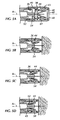
- Fig. 5A is an enlarged cross-sectional elevational view of the distal end of he autoinjector of Fig. 3 with the handle completely removed and in a pre-activation state;
- Fig. 5B is an enlarged cross-sectional elevational view of the distal end of the autoinjector of Fig. 3 with a syringe guide initially engaging flexible members of a frontal buttress;
- Fig. 5C is an enlarged cross-sectional elevational view of the distal end of the autoinjector of Fig. 3 with the syringe guide engaging an outer surface of the flexible members of the frontal buttress;
- Fig. 5D is an enlarged cross-sectional view of the distal end of the autoinjector of Fig. 3 with a shoulder of the syringe engaging a buttress surface formed by the frontal buttress;
- Fig. 6 is a side elevational view of the autoinjector of Fig. 3 ;
- Fig. 7 is a side elevational view of the autoinjector of Fig. 6 with the handle removed;
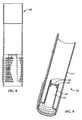
- Fig. 8 is an enlarged side elevational view of the handle of Fig. 6 ;
- Fig. 9 is a cross-sectional perspective view of the handle of Fig. 8 ;
- Fig. 10 is a top plan view of a nose of the autoinjector of Fig. 3 ;
- Fig. 11 is a cross-sectional perspective view of the nose of Fig. 10 .
- the present invention provides for an automatic injection device that includes an automatically deployable buttress upon which a syringe can be registered.
- the autoinjector 10 includes a housing 13 generally formed by various components of an injection assembly (or power pack subassembly) 12 and a window tube subassembly 14, such as an inner housing 20, a mid housing 28, a window tube 32 and a nose 40. While the present embodiment preferably includes an injection assembly 12, it is within the intent and scope of the present invention, that any injection assembly capable of automatically deploying or of causing a syringe to be automatically injected, can be used.
- exemplary automatic injection devices applicable to the present invention include those disclosed in U.S. Patent No. 6,387,078 to Gillespie, III .
- the autoinjector 10 is configured to be a modular autoinjector 10 in which the injection assembly 12 and window tube subassembly 14 can be readily assembled with a conventional syringe 46 at the time of use.
- Such conventional syringes can also include plastic syringes and cartridge based syringes.
- the injection assembly 12 includes a cap 16, an activation button 18, an inner housing 20, an injection spring 22, a plunger rod 24 having a piston 47, a spring rest 26, a mid housing 28 and an optional syringe ring 30, as best shown in Figs. 1 and 3 .
- Figs. 3 and 6 illustrate the injection assembly 12 in an assembled ready-to-use state and assembled to the window tube subassembly 14. As described hereinafter, distal refers to toward the needle-end of the autoinjector 10 and proximal refers to toward the button-end of the autoinjector 10.
- the spring rest 26 is releasably connected to about the middle of the plunger rod 24 by cooperating detents.
- the plunger rod 24 and spring rest 26 are positioned within the inner housing 20 with the injection spring 22 in between and proximal to the inner surface of the inner housing 20 and an outer surface of the spring rest 26.
- the injection spring 22 is maintained in a compressed state by catches 21 on the inner housing 20 that retain the proximal head of the plunger rod 24.
- the activation button 18 is positioned on top of the proximal end of the inner housing 20 and the cap 16 and functions to release the catches 21 to release the spring 22 upon depression.
- the foregoing assembly resides within the mid housing 28 and cap 16.
- the window tube subassembly 14 includes a window tube 32, a syringe cushion 34, a syringe guide 36, a return spring 38, a nose 40, a handle 42 and a handle cap 42a.
- Fig. 3 illustrates the syringe 46 housed within the housing 13.
- the syringe 46 includes a barrel 51 and a shoulder 52 about a distal end of the barrel 51 ( Fig. 2A ).
- Figs. 3 and 6 illustrate the window tube subassembly 14 in an assembled ready-to use state and assembled with the injection assembly 12.
- the syringe guide 36 is housed within the housing 13, is generally cylindrical in shape, and is configured to receive the barrel 51 of a syringe 46.
- the flange 62 of the syringe 46 rests upon the cushion 34 and the proximal end of the syringe guide 36 (see Fig. 3 ) and the nose 54 of the syringe 46 extends partially beyond the distal end of the syringe guide 36 (see Figs. 3 and 4A ).
- the syringe 46 moves in tandem with the syringe guide 36 upon the distal movement of the syringe guide 36.
- the handle 42 (as shown in Figs. 1 , 3 , 4A-C , 6 , 8 and 9 ) is releasably connected to the distal end of the housing 13.
- the handle 42 includes a body 63 that is generally cylindrical in shape and configured to receive the assembly of the window tube 32, syringe cushion 34, syringe 46, syringe guide 36, return spring 38 and nose 40.
- the distal end of the handle 42 is also configured with a needle shield remover 49 ( Fig. 9 ) having a generally cylindrical body 65 and latches 50 at the most proximal end of the needle shield remover 49.
- the needle shield remover 49 is integrally formed and connected to the distal end of the handle 42.
- the needle shield remover 49 can be a separate component secured to the handle 42.
- the needle shield remover 49 is configured to be received within the nose 40 and over the needle shield 60. That is, the needle shield remover 49 is sized with an outside diameter (D1) that is at least slightly smaller than the inside diameter (D2) of the flexible members 44 when in the fully opened position and an inside diameter (D3) that is at least slightly greater than the outside diameter (D4) of the needle shield 60, as best shown in Fig. 4A .
- the needle shield remover 49 is configured to maintain the plurality of radially disposed circumferentially spaced flexible members 44 in the first position ( i.e ., open position), as shown in Fig. 4A .
- the latches 50 ( Fig. 9 ) can be configured as a radially inwardly disposed flange which engages the proximal end of the needle shield 60. As a result, when the handle 42 is removed, the latches 50 engage the needle shield 60 to thereby also remove the needle shield 60 from the syringe 46.
- the latches 50 are preferably configured with a chamfered proximal surface to provide ease of assembly over the needle shield 60.
- the handle cap 42a is secured to the handle 42 and the nose 40 is assembled to the window tube 32.
- the return spring 3 8 seats within the nose 40 and the syringe guide 36 resides on top of the return spring 38 with the syringe cushion 34 residing on the syringe guide 36.
- the return spring 38, syringe guide 36 and syringe cushion 34 reside within the window tube 32, which mates with the nose 40.
- a syringe 46 e.g. , a pre-filled glass syringe, as shown in Figs.
- the syringe 46 is maintained in radial confinement within the syringe guide 36 by a running annular fit between the exterior of the syringe 46 and the interior bore of the syringe guide 36.
- the syringe 46 is maintained in axial relation to the syringe guide 36 by force applied to the proximal end of the syringe 46 by the injection spring 22 acting upon the syringe 46 through one or more components. As such, the syringe 46 and syringe guide 36 travel in tandem upon activation until the syringe 46 engages a buttress surface 45 formed by a frontal buttress 43, as shown in Fig. 5D .
- the injection assembly 12 To activate the injection assembly 12, a user removes the handle 42, and presses the nose 40 against the injection site and depresses activation button 18, thereby causing the plunger rod 24 to disengage from the inner housing 20. Upon disengagement of the plunger rod 24, the injection spring 22, which is initially in the compressed state, expands to exert a driving force on the spring rest 26 that is connected to the plunger rod 24, which subsequently causes the syringe 46 to move distally.
- the injection assembly 12 is operatively connected to the syringe 46 and configured to bias the syringe 46 from an initial position ( Fig. 4A ) in which the syringe 46 is shrouded by the housing 13 to an extended position ( Fig. 5D ) in which a portion of the syringe 46 extends beyond the housing 13.
- Figs. 5A-D , 9 and 10 illustrate a frontal buttress 43 connected to a distal end of the housing 13.
- the frontal buttress 43 includes a plurality of radially disposed circumferentially spaced flexible members 44.
- the flexible members 44 are generally configured in a pyramidal-like shape such that when in the closed position (see Fig. 5D ) the flexible members 44 form a generally frustroconical shape with the smaller diameter section proximal to the larger diameter section.
- the radially disposed circumferentially spaced flexible members 44 are located on an interior of the housing 13 and extend proximally from the distal end of the housing 13 such that the flexible members 44 collectively form a buttress surface 45 that engages the shoulder 52 of the syringe 42.
- the nose 40 is configured to include the frontal buttress 43.
- the bases 48 of each of the flexible members 44 are connected to the nose 40 along the interior distal end of the nose 40, as best shown in Figs. 5A and 11 .
- the connection of the flexible members 44 to the nose 40 is configured as a flexible connection such that the flexible members 44 can flex between a first open or spread apart position/state (as shown in Fig. 4A ) and a second closed, closer together position/state (as shown in Fig. 5D ).
- the flexible members 44 are also configured to be biased toward the closed position.
- the biasing force results from the flexible members 44 initially being molded and configured to be in the closed position and then being forced into the open position by the handle 42.
- the flexible members 44 maintain a radially inward bias. That is, the flexible members 44 flex radially inwardly when in the closed state.
- the frontal buttress 43 is configured to move from a first open position ( Fig. 4A ) when the syringe 46 is in the initial position to a second closed position ( Fig. 5D ) to engage the shoulder 52 of the syringe 46 when in the extended position.
- the flexible members 44 can be made from any polymer, such as a rigid plastic or thermoplastic elastomer.
- the flexible members 44 are made from a polyacetal or a thermoplastic elastomer.
- Figs. 4A-C the nose 40 is assembled with the handle 42.
- the handle 42 In the fully assembled state, the handle 42 is fully inserted onto the nose 40 such that the shield remover 49 of the handle 42 forces the flexible members 44 into the open position ( Fig. 4A).
- Figs. 4B and 4C illustrate various stages of removal of the handle 42 from the autoinjector 10.
- the latches 50 of the needle shield remover 49 simultaneously remove the needle shield 60.
- the bias of the flexible members 44 causes the flexible members 44 to initially move toward a centerline (A), flexing at the base 48, thereby reorienting the proximal ends of the flexible members 44 to a position within the inside diameter of the syringe guide 36 ( i.e., a pre-activation or ready-to-use state, as shown in Fig. 5A ).
- the injection assembly 12 forces the syringe guide 36 / syringe 46 assembly to engage the frontal buttress 43.
- a distal edge of the syringe guide 36 engage an outside surface of the flexible members 44.
- the outside surface of the flexible member 44 includes a chamfered or inclined surface 56 that slopes radially inwardly.
- the syringe guide 36 / syringe 46 assembly Upon continued distal movement of the syringe guide 36 / syringe 46 assembly, the distal edge of the syringe guide 36 slidingly engages the flexible members 44 causing the flexible members 44 to collectively deflect inwardly toward the centerline (A) of the autoinjector ( Fig. 5D ).
- the syringe guide 36 / syringe 46 assembly is configured such that the nose 54 of the syringe 46 initiates passage through the nose 40 of the autoinjector 10 prior to the flexible members 44 completely flexing inwardly.
- the proximal ends of the flexible members 44 advantageously provide for an effective buttress surface 45 to the shoulder 52 of the syringe 46.
- the syringe 46 remains in contact with the buttress surface 45 while liquid medicament is forced out of the syringe 46 and into the injection site.
- the flexible members 44 are also configured with a planar outside surface 58 that is oriented substantially parallel to the centerline (A) when the flexible members 44 are in the closed position, as best shown in Fig. 5D .
- the substantially parallel outside surface 58 advantageously allows for sliding engagement (or play) between the flexible members 44 and the syringe guide 36, such that the syringe guide 36 can accommodate a wide range of variability in the overall length of the syringe 46 and still function to close the flexible members 44 without bottoming out at the base 48 of the frontal buttress 43.
- the sliding relationship assures engagement of the frontal buttress 43 by the syringe 46 without risk of stressing the syringe flange 62.
- the present invention advantageously provides for an autoinjector that can accommodate a conventional syringe (such as a pre-filled glass syringe) and provide a robust means to automatically stop forward ( i.e. , distal) movement and provide a more consistent and accurate frontal position during needle insertion ( i.e ., needle insertion depth) and dose delivery, respectively, by registering the stop of needle depth insertion upon the shoulder 52 of the syringe 46 rather than the flange 62.
- a conventional syringe such as a pre-filled glass syringe
- the risk of syringe flange fracture is also significantly reduced.
- the present invention also advantageously provides for an autoinjector having an automatically deployable frontal buttress 43 such that the forward end of the syringe 46 becomes the load bearing or datum surface, thereby reducing stress on the syringe flange 62 and reducing variability in needle insertion depth by eliminating the variability associated with overall length and flange dimensions of glass syringes.
- the present invention is configured for use with conventional pre-filled syringes, such as glass staked-needle syringes, plastic syringes, and cartridge based syringes with needle hubs, there is no need for any additional sterilization of the autoinjector after assembly with the pre-filled syringe as the medicament within the pre-filled syringe is maintained within a sterile environment regardless of the sterility of the autoinjector. This helps reduce the overall costs associated with autoinjector manufacturing.
- conventional pre-filled syringes such as glass staked-needle syringes, plastic syringes, and cartridge based syringes with needle hubs
- the modular configuration of the present invention allows for pre-filled syringes to be assembled and prepared at one location and the autoinjector components to be prepared at a separate location and/or at different times, thus allowing for greater manufacturing versatility.
- the autoinjector of the present invention can be assembled with conventional pre-filled syringe at the time of use, the two devices are not constrained to a single expiration date of the device. Thus, the usability or shelf life of the autoinjector will not depend upon the expiration date of the pre-filled syringe.
Landscapes
- Health & Medical Sciences (AREA)
- Vascular Medicine (AREA)
- Engineering & Computer Science (AREA)
- Anesthesiology (AREA)
- Biomedical Technology (AREA)
- Heart & Thoracic Surgery (AREA)
- Hematology (AREA)
- Life Sciences & Earth Sciences (AREA)
- Animal Behavior & Ethology (AREA)
- General Health & Medical Sciences (AREA)
- Public Health (AREA)
- Veterinary Medicine (AREA)
- Infusion, Injection, And Reservoir Apparatuses (AREA)
Description
- The present invention relates to automatic injection devices ("autoinjectors"). In particular, the present invention relates to an autoinjector having an automatically deployable frontal buttress.
- Autoinjector mechanisms have commercially been developed to substitute an automated mechanism for the manual action of inserting a hypodermic needle into a recipient's flesh and forcing the liquid medicament out of the syringe, through the hypodermic needle and into the recipient. In some cases, the automated mechanisms are designed to utilize commercially commonplace pre-filled syringes. The pre-filled syringes are typically manufactured by pharmaceutical companies, or in some cases a third party. The manufacturers thereafter assemble the pre-filled syringes into autoinjectors for commercial distribution. Examples of such devices include the EpiPen® manufactured by Meridian Medical Technologies, Inc., of Bristol, TN, the Humira® manufactured by Owen Mumford Ltd., of Oxford, United Kingdom, and the SureClick® system marketed by Scandinavian Health Limited, of Florham Park, NJ. Autoinjectors have proven to be beneficial for patients exhibiting psychological paranoia of receiving parenteral injections (e.g., needle phobic individuals and young children) and/or those without the manual dexterity or clear eyesight necessary to self-administer injections using conventional syringes.
- Conventional autoinjectors generally provide a compression spring-based mechanism to drive the syringe in the distal direction within a housing (the housing contains the syringe) and some means to initiate the automatic injection process. When triggered, the compressed spring is released from end-to-end confinement. Typically, the spring is confined to abut against an interior surface of the housing about its proximal end such that releasing the compressed spring causes axial extension in the distal direction. The spring, typically acting through one or more surrogate components, impinges upon the syringe, and/or an elastomeric piston element thereof, causing the syringe to translate in the distal direction until the hypodermic needle associated with the syringe extends beyond the distal end of the housing.
- The extended length of the needle determines the depth of drug delivery at the injection site. The exposed length of the needle (i.e., that portion of the needle exterior to the autoinjector housing at needle extension) is known as the "needle insertion depth." The correlation between extended length and insertion depth assumes that the distal end of the autoinjector is pressed against the injection site during autoinjector actuation. In most therapeutic applications, it is important that the depth of needle insertion be accurately controlled so as to assure the drug is delivered into a specific tissue mass, for example the subcutaneous tissue residing between the dermal skin layer and the musculature. Know and repeatable length of needle insertion is therefore a desirable attribute of autoinjector devices.
- Billions of pre-filled syringes as described above are manufactured of borosilicate glass on an annual basis. The proximal end of the glass syringe is formed into a radially disposed, disk-shaped flange. The flange is thereafter cut on two sides in parallel planes in close proximity to the syringe body to form oblong and opposing finger grips. This glass syringe configuration is know as a cut-flange configuration. Glass syringes, and more particularly cut flange syringes, represent a number of challenges in autoinjector applications because they are fragile and easily broken components with a relatively high degree of dimensional variability. The high degree of dimensional variability leads to variability in the exposed length of the hypodermic needle beyond the distal end of the glass syringe and the overall length of the syringe. In addition, the cut flanges of such glass syringes have varying degrees of irregularity and asymmetry with respect to a central axis along the center of the syringe barrel and a plane perpendicular to the central axis.
- Conventional autoinjector are configured to stop the syringe at a desired forward position at the end of needle insertion based off of the syringe flange. That is, the syringe flange becomes a de facto point of registration, in other words a datum surface, which dictates the relative axial relationship between the syringe features and the other elements of the auto-injector. Under such configurations, any variability, whether associated with the overall length of the syringe, length of the exposed needle, or variability associated with the flange itself, translates directly into variability in the extended needle length and needle insertion length. In addition, due to the abrupt deceleration of the syringe/carrier assembly at the end of needle insertion, impact loads are imposed on the fragile syringe flanges. In other words, the force applied by the autoinjector in driving the syringe distally creates an opposing force imposed on the flange by its registration point of contact In addition, a bending moment is borne by the flange as a result of the radial distance between the centerline of the piston and the flange. The bending moment increases the stress applied to the fragile flange increasing the risk of fracture.
- Moreover, conventional autoinjectors are typically configured with a fixed stroke length. That is, conventional autoinjector are designed to drive the plunger of the syringe a fixed distance from some fixed reference point on the autoinjector. Thus, with increased variability in the overall length of the glass syringe used in such autoinjectors, the fixed stroke length results in increased variability of residual medicament volume after injection. Such variability in residual medicament volume translates into significant monetary waste due to the relatively high cost of the drugs used to manufacture the medicaments.
- Thus, conventional autoinjectors are deficient in that they cannot accommodate conventional pre-filled glass syringes (i.e., staked-needed syringes) to effectively address the issues associated with fragile and irregular components while assuring accurate needle placement and precise dose delivery due to the dimensional variability of glass syringe manufacturing. As such, there is still a need for an autoinjector that can provide accurate needle insertion depth and precise dose delivery.
- In addition, conventional pre-filled glass syringes are typically supplied as an assembly with a needle shield that includes an elastomeric element to provide a means to sealably encapsulate the hypodermic needle.
Fig. 2A illustrates a conventionalprefilled glass syringe 46 having abarrel 51. Theneedle shield 60 serves as a sterility barrier for the needle 61 (Fig. 2B ) and its fluid contents as thesyringe 46 is pre-sterilized at the factory. Once delivered to the pharmaceutical company, the pre-filled syringe is filled with medicament within a sterile filling suite. Often, theneedle shield 60 is itself encapsulated with a rigid component to provide additional protection against needle damage and to provide a suitable means to manually remove theneedle shield 60. Thus, theneedle shield 60 is commonly know as a rigid needle shield ("RNS"). In such RNSs, an open end allows access to the elastomeric interior through which theneedle 61 is introduced into the elastomeric interior. The RNS is removably attached to thesyringe 46 by a circumferential compression fit between the compliant elastomeric element of the RNS and cooperative features present on the distal end of thesyringe 46. In addition, such RNSs have an overall outer diameter that is approximately the same as that of thesyringe 46. - Such
conventional syringes 46 can be used as a stand alone manuallyoperable syringe 46 or in combination with a suitable autoinjector. Such autoinjectors are provided with a means to remove the RNS before administering the injection. This is typically accomplished by a component provided as part of the autoinjector that engages the needle shield during final assembly and provides a graspable handle with which a user can grasp to extract the needle shield in the axial, distal direction. However, the use of such handles to disengage the RNS creates an annular void or open end about the distal end of the autoinjector. Moreover, as the handle to remove the RNS occupies space at the distal end on the autoinjector, this precludes the use of such space for any potential buttress surface upon which thesyringe 46 may engage. - Consequently, an autoinjector that is capable of accommodating a glass, cut flange syringe with a RNS attached would present pharmaceutical companies with a significant advantage in being able to provide one primary pre-fifled syringe that can be used either in a manual setting or, alternatively, in conjunction with an autoinjector.
- A conventional autoinjector with the disadvantages discussed above is disclosed in
US-A1-2007/135767 - In accordance with the present invention, the problems associated with variability and reliability of the needle insertion depth of autoinjectors employing the use of conventional pre-filled glass syringes are solved by registering the stop of the syringe within an autoinjector based upon the front end of the syringe.
- In a preferred embodiment, the present invention comprises an autoinjector. The autoinjector includes a housing and a frontal buttress connected to a distal end of the housing. A syringe is housed within the housing and includes a barrel having a shoulder about a distal end of the barrel. An injection assembly is operatively connected to the syringe and configured to bias the syringe from an initial position in which the syringe is shrouded by the housing to an extended position in which a portion of the syringe extends beyond the housing. The frontal buttress is configured to move from a first, open position when the syringe is in the initial position to a second, closed position to engage the shoulder of the syringe when the syringe is in the extended position.
- The foregoing summary, as well as the following detailed description of a preferred embodiment of the invention, will be better understood when read in conjunction with the appended drawings. For the purpose of illustrating the invention, there is shown in the drawings an embodiment which is presently preferred. It should be understood, however, that the invention is not limited to the precise arrangements and instrumentalities shown. In the drawings:
-
Fig. 1 is an exploded elevational view of the window tube subassembly and injection assembly of an autoinjector in accordance with a preferred embodiment of the present invention; -
Fig. 2A is a perspective view of a conventional glass syringe with a rigid needle shield applicable for use within the autoinjector ofFig. 1 ; -
Fig. 2B is a side partial cross-sectional view of the syringe ofFig. 2A without the rigid needle shield; -
Fig. 3 is a cross-sectional elevational view of an autoinjector in accordance with a preferred embodiment of the present invention in a fully assembled state; -
Fig. 4A is an enlarged cross-sectional elevational view of the distal end of the autoinjector ofFig. 3 with a handle in a fully assembled position; -
Fig. 4B is an enlarged cross-sectional elevational view of the distal end of the autoinjector ofFig. 3 with the handle in a partially removed position; -
Fig. 4C is an enlarged cross-sectional elevational view of the distal end of the autoinjector ofFig. 3 with the handle in a further partially removed position; -
Fig. 5A is an enlarged cross-sectional elevational view of the distal end of he autoinjector ofFig. 3 with the handle completely removed and in a pre-activation state; -
Fig. 5B is an enlarged cross-sectional elevational view of the distal end of the autoinjector ofFig. 3 with a syringe guide initially engaging flexible members of a frontal buttress; -
Fig. 5C is an enlarged cross-sectional elevational view of the distal end of the autoinjector ofFig. 3 with the syringe guide engaging an outer surface of the flexible members of the frontal buttress; -
Fig. 5D is an enlarged cross-sectional view of the distal end of the autoinjector ofFig. 3 with a shoulder of the syringe engaging a buttress surface formed by the frontal buttress; -
Fig. 6 is a side elevational view of the autoinjector ofFig. 3 ; -
Fig. 7 is a side elevational view of the autoinjector ofFig. 6 with the handle removed; -
Fig. 8 is an enlarged side elevational view of the handle ofFig. 6 ; -
Fig. 9 is a cross-sectional perspective view of the handle ofFig. 8 ; -
Fig. 10 is a top plan view of a nose of the autoinjector ofFig. 3 ; and -
Fig. 11 is a cross-sectional perspective view of the nose ofFig. 10 . - In a preferred embodiment, the present invention provides for an automatic injection device that includes an automatically deployable buttress upon which a syringe can be registered. As shown in
Figs. 1 ,3 ,6 and 7 , theautoinjector 10 includes ahousing 13 generally formed by various components of an injection assembly (or power pack subassembly) 12 and awindow tube subassembly 14, such as aninner housing 20, amid housing 28, awindow tube 32 and anose 40. While the present embodiment preferably includes aninjection assembly 12, it is within the intent and scope of the present invention, that any injection assembly capable of automatically deploying or of causing a syringe to be automatically injected, can be used. For example, exemplary automatic injection devices applicable to the present invention include those disclosed inU.S. Patent No. 6,387,078 to Gillespie, III . In general, theautoinjector 10 is configured to be amodular autoinjector 10 in which theinjection assembly 12 andwindow tube subassembly 14 can be readily assembled with aconventional syringe 46 at the time of use. Such conventional syringes can also include plastic syringes and cartridge based syringes. - Preferably the
injection assembly 12 includes acap 16, anactivation button 18, aninner housing 20, aninjection spring 22, aplunger rod 24 having apiston 47, aspring rest 26, amid housing 28 and anoptional syringe ring 30, as best shown inFigs. 1 and3 .Figs. 3 and6 illustrate theinjection assembly 12 in an assembled ready-to-use state and assembled to thewindow tube subassembly 14. As described hereinafter, distal refers to toward the needle-end of theautoinjector 10 and proximal refers to toward the button-end of theautoinjector 10. - In an assembled state, the
spring rest 26 is releasably connected to about the middle of theplunger rod 24 by cooperating detents. Theplunger rod 24 andspring rest 26 are positioned within theinner housing 20 with theinjection spring 22 in between and proximal to the inner surface of theinner housing 20 and an outer surface of thespring rest 26. Theinjection spring 22 is maintained in a compressed state by catches 21 on theinner housing 20 that retain the proximal head of theplunger rod 24. Theactivation button 18 is positioned on top of the proximal end of theinner housing 20 and thecap 16 and functions to release thecatches 21 to release thespring 22 upon depression. The foregoing assembly resides within themid housing 28 andcap 16. - Referring back to
Fig. 1 , thewindow tube subassembly 14 includes awindow tube 32, asyringe cushion 34, asyringe guide 36, areturn spring 38, anose 40, ahandle 42 and ahandle cap 42a.Fig. 3 illustrates thesyringe 46 housed within thehousing 13. Thesyringe 46 includes abarrel 51 and ashoulder 52 about a distal end of the barrel 51 (Fig. 2A ).Figs. 3 and6 illustrate thewindow tube subassembly 14 in an assembled ready-to use state and assembled with theinjection assembly 12. - The
syringe guide 36 is housed within thehousing 13, is generally cylindrical in shape, and is configured to receive thebarrel 51 of asyringe 46. When assembled with thesyringe 46, theflange 62 of thesyringe 46 rests upon thecushion 34 and the proximal end of the syringe guide 36 (seeFig. 3 ) and thenose 54 of thesyringe 46 extends partially beyond the distal end of the syringe guide 36 (seeFigs. 3 and4A ). As a result, thesyringe 46 moves in tandem with thesyringe guide 36 upon the distal movement of thesyringe guide 36. - The handle 42 (as shown in
Figs. 1 ,3 ,4A-C ,6 ,8 and 9 ) is releasably connected to the distal end of thehousing 13. Thehandle 42 includes abody 63 that is generally cylindrical in shape and configured to receive the assembly of thewindow tube 32,syringe cushion 34,syringe 46,syringe guide 36,return spring 38 andnose 40. The distal end of thehandle 42 is also configured with a needle shield remover 49 (Fig. 9 ) having a generallycylindrical body 65 and latches 50 at the most proximal end of theneedle shield remover 49. Theneedle shield remover 49 is integrally formed and connected to the distal end of thehandle 42. Alternatively, theneedle shield remover 49 can be a separate component secured to thehandle 42. Theneedle shield remover 49 is configured to be received within thenose 40 and over theneedle shield 60. That is, theneedle shield remover 49 is sized with an outside diameter (D1) that is at least slightly smaller than the inside diameter (D2) of theflexible members 44 when in the fully opened position and an inside diameter (D3) that is at least slightly greater than the outside diameter (D4) of theneedle shield 60, as best shown inFig. 4A . Thus, theneedle shield remover 49 is configured to maintain the plurality of radially disposed circumferentially spacedflexible members 44 in the first position (i.e., open position), as shown inFig. 4A . - The latches 50 (
Fig. 9 ) can be configured as a radially inwardly disposed flange which engages the proximal end of theneedle shield 60. As a result, when thehandle 42 is removed, thelatches 50 engage theneedle shield 60 to thereby also remove theneedle shield 60 from thesyringe 46. In addition, thelatches 50 are preferably configured with a chamfered proximal surface to provide ease of assembly over theneedle shield 60. - In an assembled state, as shown in
Fig. 3 , thehandle cap 42a is secured to thehandle 42 and thenose 40 is assembled to thewindow tube 32. The return spring 3 8 seats within thenose 40 and thesyringe guide 36 resides on top of thereturn spring 38 with thesyringe cushion 34 residing on thesyringe guide 36. Thereturn spring 38,syringe guide 36 andsyringe cushion 34 reside within thewindow tube 32, which mates with thenose 40. A syringe 46 (e.g., a pre-filled glass syringe, as shown inFigs. 2A and 2B ) is inserted into thesyringe guide 36 such that thesyringe ring 30 rests upon a proximal edge of theflange 62 of thesyringe 46 and theplunger rod 24 is inserted within the barrel of thesyringe 46. Thesyringe 46 is maintained in radial confinement within thesyringe guide 36 by a running annular fit between the exterior of thesyringe 46 and the interior bore of thesyringe guide 36. Thesyringe 46 is maintained in axial relation to thesyringe guide 36 by force applied to the proximal end of thesyringe 46 by theinjection spring 22 acting upon thesyringe 46 through one or more components. As such, thesyringe 46 and syringe guide 36 travel in tandem upon activation until thesyringe 46 engages a buttresssurface 45 formed by a frontal buttress 43, as shown inFig. 5D . - To activate the
injection assembly 12, a user removes thehandle 42, and presses thenose 40 against the injection site and depressesactivation button 18, thereby causing theplunger rod 24 to disengage from theinner housing 20. Upon disengagement of theplunger rod 24, theinjection spring 22, which is initially in the compressed state, expands to exert a driving force on thespring rest 26 that is connected to theplunger rod 24, which subsequently causes thesyringe 46 to move distally. In sum, theinjection assembly 12 is operatively connected to thesyringe 46 and configured to bias thesyringe 46 from an initial position (Fig. 4A ) in which thesyringe 46 is shrouded by thehousing 13 to an extended position (Fig. 5D ) in which a portion of thesyringe 46 extends beyond thehousing 13. -
Figs. 5A-D ,9 and10 illustrate a frontal buttress 43 connected to a distal end of thehousing 13. Thefrontal buttress 43 includes a plurality of radially disposed circumferentially spacedflexible members 44. Theflexible members 44 are generally configured in a pyramidal-like shape such that when in the closed position (seeFig. 5D ) theflexible members 44 form a generally frustroconical shape with the smaller diameter section proximal to the larger diameter section. Preferably, the radially disposed circumferentially spacedflexible members 44 are located on an interior of thehousing 13 and extend proximally from the distal end of thehousing 13 such that theflexible members 44 collectively form a buttresssurface 45 that engages theshoulder 52 of thesyringe 42. - In the present embodiment, the
nose 40 is configured to include the frontal buttress 43. Thebases 48 of each of theflexible members 44 are connected to thenose 40 along the interior distal end of thenose 40, as best shown inFigs. 5A and11 . The connection of theflexible members 44 to thenose 40 is configured as a flexible connection such that theflexible members 44 can flex between a first open or spread apart position/state (as shown inFig. 4A ) and a second closed, closer together position/state (as shown inFig. 5D ). Theflexible members 44 are also configured to be biased toward the closed position. The biasing force results from theflexible members 44 initially being molded and configured to be in the closed position and then being forced into the open position by thehandle 42. As a result, due to the tensile properties of the frontal buttress 43, theflexible members 44 maintain a radially inward bias. That is, theflexible members 44 flex radially inwardly when in the closed state. - In sum, the frontal buttress 43 is configured to move from a first open position (
Fig. 4A ) when thesyringe 46 is in the initial position to a second closed position (Fig. 5D ) to engage theshoulder 52 of thesyringe 46 when in the extended position. Theflexible members 44 can be made from any polymer, such as a rigid plastic or thermoplastic elastomer. Preferably, theflexible members 44 are made from a polyacetal or a thermoplastic elastomer. - As shown in
Figs. 4A-C , thenose 40 is assembled with thehandle 42. In the fully assembled state, thehandle 42 is fully inserted onto thenose 40 such that theshield remover 49 of thehandle 42 forces theflexible members 44 into the open position (Fig. 4A). Figs. 4B and 4C illustrate various stages of removal of thehandle 42 from theautoinjector 10. As best shown inFigs. 4B and 4C , as thehandle 42 is removed, thelatches 50 of theneedle shield remover 49 simultaneously remove theneedle shield 60. After thehandle 42 is removed, the bias of theflexible members 44 causes theflexible members 44 to initially move toward a centerline (A), flexing at thebase 48, thereby reorienting the proximal ends of theflexible members 44 to a position within the inside diameter of the syringe guide 36 (i.e., a pre-activation or ready-to-use state, as shown inFig. 5A ). - After the
handle 42 is removed and upon activation of theautoinjector 10, theinjection assembly 12 forces thesyringe guide 36 /syringe 46 assembly to engage the frontal buttress 43. As shown inFigs. 5A-5D , as thesyringe guide 36 /syringe 46 assembly moves distally, a distal edge of thesyringe guide 36 engage an outside surface of theflexible members 44. Preferably, the outside surface of theflexible member 44 includes a chamfered orinclined surface 56 that slopes radially inwardly. Upon continued distal movement of thesyringe guide 36 /syringe 46 assembly, the distal edge of thesyringe guide 36 slidingly engages theflexible members 44 causing theflexible members 44 to collectively deflect inwardly toward the centerline (A) of the autoinjector (Fig. 5D ). Preferably, thesyringe guide 36 /syringe 46 assembly is configured such that thenose 54 of thesyringe 46 initiates passage through thenose 40 of theautoinjector 10 prior to theflexible members 44 completely flexing inwardly. Upon full deployment of thesyringe 46, by the radial confinement and column strength of theflexible members 44, the proximal ends of theflexible members 44 advantageously provide for an effective buttresssurface 45 to theshoulder 52 of thesyringe 46. Moreover, at the end of needle insertion and once thesyringe 46 abuts against the buttress surface 45 (as shown inFig. 5D ) thesyringe 46 remains in contact with the buttresssurface 45 while liquid medicament is forced out of thesyringe 46 and into the injection site. - Preferably, the
flexible members 44 are also configured with a planaroutside surface 58 that is oriented substantially parallel to the centerline (A) when theflexible members 44 are in the closed position, as best shown inFig. 5D . The substantially paralleloutside surface 58 advantageously allows for sliding engagement (or play) between theflexible members 44 and thesyringe guide 36, such that thesyringe guide 36 can accommodate a wide range of variability in the overall length of thesyringe 46 and still function to close theflexible members 44 without bottoming out at thebase 48 of the frontal buttress 43. Moreover, the sliding relationship assures engagement of the frontal buttress 43 by thesyringe 46 without risk of stressing thesyringe flange 62. - In sum, the present invention advantageously provides for an autoinjector that can accommodate a conventional syringe (such as a pre-filled glass syringe) and provide a robust means to automatically stop forward (i.e., distal) movement and provide a more consistent and accurate frontal position during needle insertion (i.e., needle insertion depth) and dose delivery, respectively, by registering the stop of needle depth insertion upon the
shoulder 52 of thesyringe 46 rather than theflange 62. By eliminating the load on thesyringe flange 62, the risk of syringe flange fracture is also significantly reduced. Moreover, the accuracy of dose delivery and reduction in residual fluid volume within the syringe post-injection is significantly enhanced, thus saving considerable costs associated with manufacturing pre-filled syringes. The present invention also advantageously provides for an autoinjector having an automatically deployable frontal buttress 43 such that the forward end of thesyringe 46 becomes the load bearing or datum surface, thereby reducing stress on thesyringe flange 62 and reducing variability in needle insertion depth by eliminating the variability associated with overall length and flange dimensions of glass syringes. - In addition, as the present invention is configured for use with conventional pre-filled syringes, such as glass staked-needle syringes, plastic syringes, and cartridge based syringes with needle hubs, there is no need for any additional sterilization of the autoinjector after assembly with the pre-filled syringe as the medicament within the pre-filled syringe is maintained within a sterile environment regardless of the sterility of the autoinjector. This helps reduce the overall costs associated with autoinjector manufacturing. In addition, because of the modular configuration of the present invention, it allows for pre-filled syringes to be assembled and prepared at one location and the autoinjector components to be prepared at a separate location and/or at different times, thus allowing for greater manufacturing versatility. Moreover, as the autoinjector of the present invention can be assembled with conventional pre-filled syringe at the time of use, the two devices are not constrained to a single expiration date of the device. Thus, the usability or shelf life of the autoinjector will not depend upon the expiration date of the pre-filled syringe.
- It will be appreciated by those skilled in the art that changes could be made to the embodiment described above without departing from the broad inventive concept thereof. It is understood, therefore, that this invention is not limited to the particular embodiment disclosed, but is intended to cover modifications within the scope of the present invention as defined by the claims.
Claims (16)
- An autoinjector (10) comprising:a housing (13);a syringe (46) housed within the housing (13), the syringe (46) including a barrel (51) having a shoulder (52) about a distal end of the barrel (51); and an injection assembly (12) operatively connected to the syringe (46) and configured to bias the syringe (46) from an initial position in which the syringe (46) is shrouded by the housing (13) to an extended position in which a portion of the syringe (46) extends beyond the housing (13), CHARACTERIZED IN THATa frontal buttress (43) is connected to a distal end of the housing (13);the frontal buttress (43) being configured to move from a first open position when the syringe (46) is in the initial position to a second closed position to engage the shoulder (52) of the syringe (46) when the syringe (46) is in the extended position.
- The autoinjector (10) of claim 1, wherein the frontal buttress (43) comprises a plurality of radially disposed circumferentially spaced flexible members (44) connected to the distal end of the housing (13), wherein each of the flexible members (44) flexes from the first position in which the flexible members (44) are in an open state to the second position in which the plurality of flexible (44) members are in a closed state.
- The autoinjector (10) of claim 2, wherein at least a proximal end of each of the flexible members (44) flexes radially inwardly when in the closed state.
- The autoinjector (10) of claim 2, wherein the radially disposed circumferentially spaced flexible members (10) are located on an interior of the housing (13) and extend proximally from the distal end of the housing (13) such that the flexible members (44) collectively form a buttress surface that engages the shoulder (52) of the syringe (46).
- The autoinjector (10) of claim 2, further comprising a syringe guide (36) within the housing (13), wherein the syringe (46) is located within the syringe guide (36) and moves in tandem with the syringe guide (36) upon the distal movement of the syringe guide (36) and wherein a distal edge of the syringe guide (36) engages and moves each of the radially disposed circumferentially spaced flexible members (44) inwardly.
- The autoinjector (10) of claim 2, further comprising a handle (42) releasably connected to the distal end of the housing (13), the handle (42) including:a cylindrical body (63); anda needle shield remover (49) connected to the cylindrical body (63) and configured to remove a needle shield (60).
- The autoinjector (10) of claim 6, wherein the needle shield remover (49) comprises:a generally cylindrical body; anda latch (50) for engaging a proximal end of the needle shield (60).
- The autoinjector (10) of claim 6, wherein the needle shield remover (49) is configured to maintain the plurality of radially disposed circumferentially spaced flexible members (44) in the first position.
- The autoinjector (10) of claim 1, wherein the syringe (46) is one of a pre-filled syringe and a staked-needle syringe.
- The autoinjector of claim 1, wherein the syringe (46) supports a needle (61); the injection assembly is a drive mechanism capable of moving the syringe (46) to the extended position; and the frontal buttress (43) includes a plurality of flexible members (44) movable between the first open position and the second closed position, wherein the first open position has a first radial orientation and the second closed position has a second radial orientation and further comprising a needle shield (60) for covering the needle.
- The autoinjector (10) of claim 10, wherein with the syringe (46) in the initial position and the flexible members (44) in the first radial orientation, at least a portion of the needle shield (60) fits within the members (44) and with the syringe (46) in the extended position and the flexible members (46) in the second radial orientation, the flexible members (44) engage the shoulder (52),
- The autoinjector (10) of claim 11, further comprising a syringe guide (36) that moves with the syringe (46) as the syringe (46) moves from the initial position to the extended position, wherein the syringe guide (36) engages the flexible members (44) to move the flexible members (44) at least a portion of the way from the first radial orientation to the second radial orientation.
- The autoinjector (10) of claim 11, wherein the flexible members (44) each have a first end attached to a supporting structure and a second end pivotable about the first end and attached to the housing (13) and wherein the second end pivots radially inwardly as the flexible member (44) moves from the first radial orientation to the second radial orientation.
- The autoinjector (10) of claim 11, further comprising a cap (42a) including a needle shield removal element engaged with the needle shield (60) and wherein the flexible members (44) are biased into the first radial orientation, by engagement of the flexible members (44) with the needle shield removal element
- The autoinjector (10) of claim 14, wherein, with the needle shield (60) engaged with the needle shield removal element, removal of the cap (42a) from the housing (13) also removes the needle shield (60) from the needle (61).
- The autoinjector of claim 15, wherein upon removal of the cap and needle shield (60), the flexible members (44) move from the first radial orientation toward the second radial orientation due to elasticity of the flexible members.
Applications Claiming Priority (2)
| Application Number | Priority Date | Filing Date | Title |
|---|---|---|---|
| US7425308P | 2008-06-20 | 2008-06-20 | |
| PCT/US2009/047483 WO2009155277A1 (en) | 2008-06-20 | 2009-06-16 | Automatic injection mechanism with frontal buttress |
Publications (4)
| Publication Number | Publication Date |
|---|---|
| EP2288398A1 EP2288398A1 (en) | 2011-03-02 |
| EP2288398A4 EP2288398A4 (en) | 2011-08-24 |
| EP2288398B1 true EP2288398B1 (en) | 2013-01-02 |
| EP2288398B8 EP2288398B8 (en) | 2013-07-31 |
Family
ID=41434408
Family Applications (1)
| Application Number | Title | Priority Date | Filing Date |
|---|---|---|---|
| EP09713663.4A Active EP2288398B8 (en) | 2008-06-20 | 2009-06-16 | Automatic injection mechanism with frontal buttress |
Country Status (6)
| Country | Link |
|---|---|
| US (1) | US8900197B2 (en) |
| EP (1) | EP2288398B8 (en) |
| JP (1) | JP2011524792A (en) |
| CN (1) | CN102065938B (en) |
| BR (1) | BRPI0910000B8 (en) |
| WO (1) | WO2009155277A1 (en) |
Families Citing this family (62)
| Publication number | Priority date | Publication date | Assignee | Title |
|---|---|---|---|---|
| ATE409057T1 (en) | 2002-02-11 | 2008-10-15 | Antares Pharma Inc | INTRADERMAL INJECTION DEVICE |
| GB0414054D0 (en) | 2004-06-23 | 2004-07-28 | Owen Mumford Ltd | Improvements relating to automatic injection devices |
| WO2006079064A1 (en) | 2005-01-24 | 2006-07-27 | Antares Pharma, Inc. | Prefilled needle assisted jet injector |
| US8251947B2 (en) | 2006-05-03 | 2012-08-28 | Antares Pharma, Inc. | Two-stage reconstituting injector |
| TWI498137B (en) | 2006-06-30 | 2015-09-01 | Abbvie Biotechnology Ltd | Automatic injection device |
| EP3581224A1 (en) | 2008-08-05 | 2019-12-18 | Antares Pharma, Inc. | Multiple dosage injector |
| AU2010226442A1 (en) | 2009-03-20 | 2011-10-13 | Antares Pharma, Inc. | Hazardous agent injection system |
| MX2011011541A (en) | 2009-04-29 | 2012-02-28 | Abbott Biotech Ltd | Automatic injection device. |
| GB2471473A (en) * | 2009-06-30 | 2011-01-05 | Owen Mumford Ltd | Syringe sheath remover |
| GB201002327D0 (en) * | 2010-02-11 | 2010-03-31 | Liversidge Barry P | Medical needle cover seal |
| US9259536B2 (en) | 2010-04-20 | 2016-02-16 | West Pharmaceutical Services, Inc. | Automatic injection syringe assembly with integrated, fillable medicine container and method of filling an injection syringe assembly |
| GB201006789D0 (en) * | 2010-04-23 | 2010-06-09 | Liversidge Barry P | Safety needle device |
| FR2961403B1 (en) * | 2010-06-17 | 2013-06-14 | Rexam Healthcare La Verpillier | SET OF A SYRINGE AND A SAFETY DEVICE |
| MX336571B (en) | 2011-01-24 | 2016-01-25 | Elcam Medical Agricultural Cooperative Ass Ltd | INJECTOR. |
| RU2602039C2 (en) | 2011-01-24 | 2016-11-10 | Эббви Байотекнолоджи Лтд. | Automatic injection devices having overmoulded gripping surfaces |
| MX388000B (en) * | 2011-01-24 | 2025-03-19 | Abbvie Biotechnology Ltd | SEPARATION OF NEEDLE GUARDS FROM SYRINGES AND AUTOMATIC INJECTION DEVICES. |
| US9173999B2 (en) * | 2011-01-26 | 2015-11-03 | Kaleo, Inc. | Devices and methods for delivering medicaments from a multi-chamber container |
| DE102011107199A1 (en) * | 2011-07-13 | 2013-01-17 | Haselmeier Gmbh | Injection device and method for its production |
| US9220660B2 (en) | 2011-07-15 | 2015-12-29 | Antares Pharma, Inc. | Liquid-transfer adapter beveled spike |
| US8496619B2 (en) | 2011-07-15 | 2013-07-30 | Antares Pharma, Inc. | Injection device with cammed ram assembly |
| RU2568424C1 (en) * | 2011-10-17 | 2015-11-20 | Схл Груп Аб | Device for removing protective caps of components for delivery |
| CN103974734B (en) * | 2011-10-17 | 2016-11-09 | Shl集团有限责任公司 | For removing the device of transfer member guard shield |
| EP2601992A1 (en) | 2011-12-08 | 2013-06-12 | Sanofi-Aventis Deutschland GmbH | Syringe carrier |
| EP2833944A4 (en) | 2012-04-06 | 2016-05-25 | Antares Pharma Inc | NEEDLE ASSISTED JET INJECTION ADMINISTRATION OF TESTOSTERONE COMPOSITIONS |
| US20140142500A1 (en) * | 2012-04-23 | 2014-05-22 | Zogenix, Inc. | Piston closures for drug delivery capsules |
| US9364610B2 (en) | 2012-05-07 | 2016-06-14 | Antares Pharma, Inc. | Injection device with cammed ram assembly |
| EP2679262B1 (en) * | 2012-06-25 | 2015-02-25 | Becton Dickinson France | Prefillable drug delivery device |
| JP5954011B2 (en) * | 2012-07-18 | 2016-07-20 | 凸版印刷株式会社 | Microneedle penetration control device |
| JP5954014B2 (en) * | 2012-07-20 | 2016-07-20 | 凸版印刷株式会社 | Microneedle penetration control device |
| US9675754B2 (en) * | 2012-10-24 | 2017-06-13 | Nuance Designs, LLC | Autoinjector |
| PT2953667T (en) | 2013-02-11 | 2020-01-28 | Antares Pharma Inc | NEEDLE-ASSISTED JET INJECTION DEVICE WITH REDUCED TRIGGER STRENGTH |
| JP6030803B2 (en) | 2013-03-11 | 2016-11-24 | アンタレス・ファーマ・インコーポレーテッド | Dose syringe with pinion system |
| EP2777684A1 (en) | 2013-03-14 | 2014-09-17 | Sanofi-Aventis Deutschland GmbH | Medicament container carrier and adapter |
| DK2745866T3 (en) | 2014-01-30 | 2017-01-23 | Tecpharma Licensing Ag | Release safety device for an auto-injector |
| US10751470B2 (en) | 2014-02-10 | 2020-08-25 | E3D A.C.A.L Ltd | Semi disposable auto injector |
| AU2015372441A1 (en) | 2014-12-23 | 2017-08-10 | Automed Pty Ltd | Delivery apparatus, system and associated methods |
| US20200384209A1 (en) * | 2015-04-24 | 2020-12-10 | Shl Medical Ag | Drive mechanism |
| TW201705994A (en) * | 2015-06-03 | 2017-02-16 | 賽諾菲阿凡提斯德意志有限公司 | Automatic syringe and assembly method |
| TW201700117A (en) | 2015-06-03 | 2017-01-01 | 賽諾菲阿凡提斯德意志有限公司 | Syringe bracket and assembly method for autoinjector |
| EP3307348A2 (en) * | 2015-06-15 | 2018-04-18 | Nuance Designs of CT, LLC | Gas-propelled autoinjector with gas flow regulator |
| AU2016287571C1 (en) | 2015-06-30 | 2021-12-23 | Kaleo, Inc. | Auto-injectors for administration of a medicament within a prefilled syringe |
| WO2017033193A2 (en) | 2015-08-27 | 2017-03-02 | E3D Agricultural Cooperative Association Ltd | Reusable automatic injection device |
| GB201607491D0 (en) * | 2016-04-29 | 2016-06-15 | Owen Mumford Ltd | Injection devices |
| PT3622986T (en) * | 2016-06-03 | 2021-05-31 | Shl Medical Ag | Medicament delivery device |
| USD821572S1 (en) * | 2016-06-20 | 2018-06-26 | Medimmune, Llc | Drug delivery implement with translucent housing |
| CA3027992C (en) | 2016-06-22 | 2021-08-03 | Antares Pharma, Inc. | Needle-shield remover |
| USD822199S1 (en) * | 2016-06-22 | 2018-07-03 | Medimmune, Llc | Drug delivery implement |
| JP7012702B2 (en) * | 2016-07-14 | 2022-01-28 | サノフィ-アベンティス・ドイチュラント・ゲゼルシャフト・ミット・ベシュレンクテル・ハフツング | Drug delivery device |
| EP3484556B1 (en) * | 2016-07-14 | 2023-07-05 | Sanofi-Aventis Deutschland GmbH | Drug delivery device with controlled needle shield and cover sleeve |
| FR3055101B1 (en) * | 2016-08-16 | 2021-12-10 | Nemera La Verpilliere | AUTOMATIC INJECTION DEVICE WITH IMPROVED SYRINGE RETENTION. |
| GB201616393D0 (en) * | 2016-09-27 | 2016-11-09 | Owen Mumford Ltd | Auto-injector |
| WO2018119218A1 (en) | 2016-12-23 | 2018-06-28 | Kaleo, Inc. | Medicament delivery device and methods for delivering drugs to infants and children |
| WO2018136840A1 (en) * | 2017-01-20 | 2018-07-26 | L.G.P. Technology Holdings Llc | Auto-injector device |
| WO2019125699A1 (en) * | 2017-12-21 | 2019-06-27 | Tact Ip, Llc | Auto-injector devices to facilitate perispinal delivery of biologics and drugs |
| AU2019208338B2 (en) | 2018-01-19 | 2024-11-07 | Birya Biotech, Inc. | Tool for servicing an auto-injector |
| PT3801694T (en) | 2018-06-08 | 2025-10-30 | Antares Pharma Inc | Auto-insert injector |
| EP3902584A4 (en) | 2018-12-29 | 2022-09-07 | Kaleo, Inc. | DEVICES AND METHODS FOR DELIVERING SUBSTANCES IN A PRE-FILLED SYRINGE |
| WO2020216918A1 (en) | 2019-04-26 | 2020-10-29 | Becton Dickinson France | Needle cover with undercut |
| US11167087B2 (en) | 2019-08-09 | 2021-11-09 | Kaleo, Inc. | Devices and methods for delivery of substances within a prefilled syringe |
| US20220305213A1 (en) * | 2019-08-12 | 2022-09-29 | West Pharmaceutical Services, Inc. | Palm activated drug delivery device |
| US11957542B2 (en) | 2020-04-30 | 2024-04-16 | Automed Patent Holdco, Llc | Sensing complete injection for animal injection device |
| US12268847B1 (en) | 2021-02-10 | 2025-04-08 | Kaleo, Inc. | Devices and methods for delivery of substances within a medicament container |
Citations (1)
| Publication number | Priority date | Publication date | Assignee | Title |
|---|---|---|---|---|
| US20070173770A1 (en) * | 2006-01-23 | 2007-07-26 | The Medical House Plc | Injection device |
Family Cites Families (24)
| Publication number | Priority date | Publication date | Assignee | Title |
|---|---|---|---|---|
| US4640686A (en) * | 1986-02-24 | 1987-02-03 | Survival Technology, Inc. | Audible signal autoinjector training device |
| US5451210A (en) * | 1991-04-29 | 1995-09-19 | Lifequest Medical, Inc. | System and method for rapid vascular drug delivery |
| EP0680767A1 (en) * | 1994-05-06 | 1995-11-08 | Nardino Righi | Non-reusable safety syringe |
| US5843036A (en) * | 1996-08-23 | 1998-12-01 | Becton Dickinson And Company | Non-dosing cartridge for an injection device |
| GB9714948D0 (en) * | 1997-07-16 | 1997-09-17 | Owen Mumford Ltd | Improvements relating to injection devices |
| DE69827036T2 (en) * | 1997-12-16 | 2006-03-09 | Meridian Medical Technologies, Inc. | AUTOMATIC INJECTION DEVICE FOR THE ADMINISTRATION OF A MEDICAMENT |
| US6428528B2 (en) * | 1998-08-11 | 2002-08-06 | Antares Pharma, Inc. | Needle assisted jet injector |
| US6986760B2 (en) * | 2000-08-02 | 2006-01-17 | Becton, Dickinson And Company | Pen needle and safety shield system |
| WO2002009797A1 (en) * | 2000-08-02 | 2002-02-07 | Becton Dickinson And Company | Pen needle and safety shield system |
| US20040193110A1 (en) * | 2002-02-07 | 2004-09-30 | Lucio Giambattista | Pen needle and safety shield system |
| SE518981C2 (en) * | 2000-12-14 | 2002-12-17 | Shl Medical Ab | autoinjector |
| US6387078B1 (en) * | 2000-12-21 | 2002-05-14 | Gillespie, Iii Richard D. | Automatic mixing and injecting apparatus |
| EP1443992B1 (en) * | 2001-11-09 | 2007-01-03 | Alza Corporation | Collapsible syringe cartridge |
| GB0229345D0 (en) * | 2002-12-17 | 2003-01-22 | Safe T Ltd | Hollow needle applicators |
| IL157981A (en) * | 2003-09-17 | 2014-01-30 | Elcam Medical Agricultural Cooperative Ass Ltd | Auto-injector |
| DE10351598A1 (en) * | 2003-11-05 | 2005-06-16 | Tecpharma Licensing Ag | Auto-injection device |
| GB0327136D0 (en) * | 2003-11-21 | 2003-12-24 | Nmt Group Plc | Safety needle |
| GB2410188B (en) * | 2004-01-23 | 2006-01-25 | Medical House Plc | Injection device |
| GB2414400B (en) * | 2004-05-28 | 2009-01-14 | Cilag Ag Int | Injection device |
| EP1814616A1 (en) * | 2004-11-04 | 2007-08-08 | Sid Technologies Llc | Automatic injector |
| US7297136B2 (en) * | 2004-12-06 | 2007-11-20 | Wyrick Ronald E | Medicine injection devices and methods |
| US7988675B2 (en) * | 2005-12-08 | 2011-08-02 | West Pharmaceutical Services Of Delaware, Inc. | Automatic injection and retraction devices for use with pre-filled syringe cartridges |
| GB0601309D0 (en) * | 2006-01-23 | 2006-03-01 | Medical House The Plc | Injection device |
| US20090005737A1 (en) * | 2007-06-29 | 2009-01-01 | Thomas Chun | Auto-Injector |
-
2009
- 2009-06-16 CN CN200980123335.XA patent/CN102065938B/en active Active
- 2009-06-16 WO PCT/US2009/047483 patent/WO2009155277A1/en not_active Ceased
- 2009-06-16 US US12/530,539 patent/US8900197B2/en active Active
- 2009-06-16 EP EP09713663.4A patent/EP2288398B8/en active Active
- 2009-06-16 BR BRPI0910000A patent/BRPI0910000B8/en active IP Right Grant
- 2009-06-16 JP JP2011514743A patent/JP2011524792A/en active Pending
Patent Citations (1)
| Publication number | Priority date | Publication date | Assignee | Title |
|---|---|---|---|---|
| US20070173770A1 (en) * | 2006-01-23 | 2007-07-26 | The Medical House Plc | Injection device |
Also Published As
| Publication number | Publication date |
|---|---|
| CN102065938B (en) | 2014-09-03 |
| EP2288398A1 (en) | 2011-03-02 |
| BRPI0910000A2 (en) | 2016-01-19 |
| US20110034879A1 (en) | 2011-02-10 |
| WO2009155277A1 (en) | 2009-12-23 |
| EP2288398B8 (en) | 2013-07-31 |
| BRPI0910000B8 (en) | 2021-06-22 |
| CN102065938A (en) | 2011-05-18 |
| US8900197B2 (en) | 2014-12-02 |
| JP2011524792A (en) | 2011-09-08 |
| BRPI0910000B1 (en) | 2019-08-06 |
| EP2288398A4 (en) | 2011-08-24 |
Similar Documents
| Publication | Publication Date | Title |
|---|---|---|
| US8900197B2 (en) | Automatic injection mechanism with frontal buttress | |
| US8048029B2 (en) | Injector apparatus | |
| CN103328024B (en) | Driving assembly and the method for assembling automatic injector for automatic injector | |
| US20250144297A1 (en) | Medicament delivery devices for administration of a medicament within a prefilled syringe | |
| JP6843909B2 (en) | Drug delivery device | |
| US11135371B2 (en) | Apparatuses and method for injecting medicaments | |
| JP5043866B2 (en) | Improved auto-injector that supports the syringe in front | |
| JP6138129B2 (en) | Injection device | |
| DK2817047T3 (en) | DEVICES FOR TARGETED IMPROVEMENT OF THERAPEUTIC IMPLANTS | |
| DK2654831T3 (en) | autoinjector | |
| CN104582767B (en) | Retracting Needle Safety Syringes | |
| US9737663B2 (en) | Auto-injector | |
| US20210128836A1 (en) | Power unit for use in an autoinjector and method of assembling such power unit | |
| TW201509473A (en) | Plunger-driven auto-injectors | |
| CN101180090A (en) | Auto-Inject and Retract Syringes | |
| CN119212749A (en) | Injection device comprising a releasable snap-fit connection for a closure cap | |
| EP4309704A1 (en) | An injection device comprising a closure cap that can be removed together with an electronic module | |
| EP4427773A1 (en) | Resettable autoinjector | |
| GB2504128A (en) | Automatic injector with a skin contact element |
Legal Events
| Date | Code | Title | Description |
|---|---|---|---|
| PUAI | Public reference made under article 153(3) epc to a published international application that has entered the european phase |
Free format text: ORIGINAL CODE: 0009012 |
|
| 17P | Request for examination filed |
Effective date: 20090901 |
|
| AK | Designated contracting states |
Kind code of ref document: A1 Designated state(s): AT BE BG CH CY CZ DE DK EE ES FI FR GB GR HR HU IE IS IT LI LT LU LV MC MK MT NL NO PL PT RO SE SI SK TR |
|
| AX | Request for extension of the european patent |
Extension state: AL BA RS |
|
| R17P | Request for examination filed (corrected) |
Effective date: 20090901 |
|
| R17P | Request for examination filed (corrected) |
Effective date: 20090901 |
|
| R17P | Request for examination filed (corrected) |
Effective date: 20090901 |
|
| A4 | Supplementary search report drawn up and despatched |
Effective date: 20110727 |
|
| RIC1 | Information provided on ipc code assigned before grant |
Ipc: A61M 5/32 20060101ALI20110721BHEP Ipc: A61M 5/20 20060101AFI20110721BHEP Ipc: A61M 5/46 20060101ALI20110721BHEP Ipc: A61M 5/31 20060101ALN20110721BHEP |
|
| DAX | Request for extension of the european patent (deleted) | ||
| RIC1 | Information provided on ipc code assigned before grant |
Ipc: A61M 5/46 20060101ALI20120319BHEP Ipc: A61M 5/32 20060101ALI20120319BHEP Ipc: A61M 5/31 20060101ALN20120319BHEP Ipc: A61M 5/20 20060101AFI20120319BHEP |
|
| GRAP | Despatch of communication of intention to grant a patent |
Free format text: ORIGINAL CODE: EPIDOSNIGR1 |
|
| GRAS | Grant fee paid |
Free format text: ORIGINAL CODE: EPIDOSNIGR3 |
|
| GRAA | (expected) grant |
Free format text: ORIGINAL CODE: 0009210 |
|
| AK | Designated contracting states |
Kind code of ref document: B1 Designated state(s): AT BE BG CH CY CZ DE DK EE ES FI FR GB GR HR HU IE IS IT LI LT LU LV MC MK MT NL NO PL PT RO SE SI SK TR |
|
| REG | Reference to a national code |
Ref country code: GB Ref legal event code: FG4D |
|
| REG | Reference to a national code |
Ref country code: AT Ref legal event code: REF Ref document number: 591224 Country of ref document: AT Kind code of ref document: T Effective date: 20130115 Ref country code: CH Ref legal event code: EP |
|
| REG | Reference to a national code |
Ref country code: IE Ref legal event code: FG4D |
|
| REG | Reference to a national code |
Ref country code: DE Ref legal event code: R096 Ref document number: 602009012431 Country of ref document: DE Effective date: 20130307 |
|
| REG | Reference to a national code |
Ref country code: AT Ref legal event code: MK05 Ref document number: 591224 Country of ref document: AT Kind code of ref document: T Effective date: 20130102 |
|
| REG | Reference to a national code |
Ref country code: NL Ref legal event code: VDEP Effective date: 20130102 |
|
| PG25 | Lapsed in a contracting state [announced via postgrant information from national office to epo] |
Ref country code: SI Free format text: LAPSE BECAUSE OF FAILURE TO SUBMIT A TRANSLATION OF THE DESCRIPTION OR TO PAY THE FEE WITHIN THE PRESCRIBED TIME-LIMIT Effective date: 20130102 |
|
| REG | Reference to a national code |
Ref country code: LT Ref legal event code: MG4D |
|
| PG25 | Lapsed in a contracting state [announced via postgrant information from national office to epo] |
Ref country code: LT Free format text: LAPSE BECAUSE OF FAILURE TO SUBMIT A TRANSLATION OF THE DESCRIPTION OR TO PAY THE FEE WITHIN THE PRESCRIBED TIME-LIMIT Effective date: 20130102 Ref country code: BG Free format text: LAPSE BECAUSE OF FAILURE TO SUBMIT A TRANSLATION OF THE DESCRIPTION OR TO PAY THE FEE WITHIN THE PRESCRIBED TIME-LIMIT Effective date: 20130402 Ref country code: ES Free format text: LAPSE BECAUSE OF FAILURE TO SUBMIT A TRANSLATION OF THE DESCRIPTION OR TO PAY THE FEE WITHIN THE PRESCRIBED TIME-LIMIT Effective date: 20130413 Ref country code: BE Free format text: LAPSE BECAUSE OF FAILURE TO SUBMIT A TRANSLATION OF THE DESCRIPTION OR TO PAY THE FEE WITHIN THE PRESCRIBED TIME-LIMIT Effective date: 20130102 Ref country code: SE Free format text: LAPSE BECAUSE OF FAILURE TO SUBMIT A TRANSLATION OF THE DESCRIPTION OR TO PAY THE FEE WITHIN THE PRESCRIBED TIME-LIMIT Effective date: 20130102 Ref country code: AT Free format text: LAPSE BECAUSE OF FAILURE TO SUBMIT A TRANSLATION OF THE DESCRIPTION OR TO PAY THE FEE WITHIN THE PRESCRIBED TIME-LIMIT Effective date: 20130102 Ref country code: NO Free format text: LAPSE BECAUSE OF FAILURE TO SUBMIT A TRANSLATION OF THE DESCRIPTION OR TO PAY THE FEE WITHIN THE PRESCRIBED TIME-LIMIT Effective date: 20130402 Ref country code: IS Free format text: LAPSE BECAUSE OF FAILURE TO SUBMIT A TRANSLATION OF THE DESCRIPTION OR TO PAY THE FEE WITHIN THE PRESCRIBED TIME-LIMIT Effective date: 20130502 Ref country code: CZ Free format text: LAPSE BECAUSE OF FAILURE TO SUBMIT A TRANSLATION OF THE DESCRIPTION OR TO PAY THE FEE WITHIN THE PRESCRIBED TIME-LIMIT Effective date: 20130102 |
|
| PG25 | Lapsed in a contracting state [announced via postgrant information from national office to epo] |
Ref country code: NL Free format text: LAPSE BECAUSE OF FAILURE TO SUBMIT A TRANSLATION OF THE DESCRIPTION OR TO PAY THE FEE WITHIN THE PRESCRIBED TIME-LIMIT Effective date: 20130102 Ref country code: PL Free format text: LAPSE BECAUSE OF FAILURE TO SUBMIT A TRANSLATION OF THE DESCRIPTION OR TO PAY THE FEE WITHIN THE PRESCRIBED TIME-LIMIT Effective date: 20130102 Ref country code: GR Free format text: LAPSE BECAUSE OF FAILURE TO SUBMIT A TRANSLATION OF THE DESCRIPTION OR TO PAY THE FEE WITHIN THE PRESCRIBED TIME-LIMIT Effective date: 20130403 Ref country code: FI Free format text: LAPSE BECAUSE OF FAILURE TO SUBMIT A TRANSLATION OF THE DESCRIPTION OR TO PAY THE FEE WITHIN THE PRESCRIBED TIME-LIMIT Effective date: 20130102 Ref country code: MC Free format text: LAPSE BECAUSE OF NON-PAYMENT OF DUE FEES Effective date: 20130131 Ref country code: LV Free format text: LAPSE BECAUSE OF FAILURE TO SUBMIT A TRANSLATION OF THE DESCRIPTION OR TO PAY THE FEE WITHIN THE PRESCRIBED TIME-LIMIT Effective date: 20130102 Ref country code: PT Free format text: LAPSE BECAUSE OF FAILURE TO SUBMIT A TRANSLATION OF THE DESCRIPTION OR TO PAY THE FEE WITHIN THE PRESCRIBED TIME-LIMIT Effective date: 20130502 |
|
| PG25 | Lapsed in a contracting state [announced via postgrant information from national office to epo] |
Ref country code: HR Free format text: LAPSE BECAUSE OF FAILURE TO SUBMIT A TRANSLATION OF THE DESCRIPTION OR TO PAY THE FEE WITHIN THE PRESCRIBED TIME-LIMIT Effective date: 20130102 |
|
| PG25 | Lapsed in a contracting state [announced via postgrant information from national office to epo] |
Ref country code: SK Free format text: LAPSE BECAUSE OF FAILURE TO SUBMIT A TRANSLATION OF THE DESCRIPTION OR TO PAY THE FEE WITHIN THE PRESCRIBED TIME-LIMIT Effective date: 20130102 Ref country code: EE Free format text: LAPSE BECAUSE OF FAILURE TO SUBMIT A TRANSLATION OF THE DESCRIPTION OR TO PAY THE FEE WITHIN THE PRESCRIBED TIME-LIMIT Effective date: 20130102 Ref country code: RO Free format text: LAPSE BECAUSE OF FAILURE TO SUBMIT A TRANSLATION OF THE DESCRIPTION OR TO PAY THE FEE WITHIN THE PRESCRIBED TIME-LIMIT Effective date: 20130102 Ref country code: DK Free format text: LAPSE BECAUSE OF FAILURE TO SUBMIT A TRANSLATION OF THE DESCRIPTION OR TO PAY THE FEE WITHIN THE PRESCRIBED TIME-LIMIT Effective date: 20130102 |
|
| PLBE | No opposition filed within time limit |
Free format text: ORIGINAL CODE: 0009261 |
|
| STAA | Information on the status of an ep patent application or granted ep patent |
Free format text: STATUS: NO OPPOSITION FILED WITHIN TIME LIMIT |
|
| PG25 | Lapsed in a contracting state [announced via postgrant information from national office to epo] |
Ref country code: CY Free format text: LAPSE BECAUSE OF FAILURE TO SUBMIT A TRANSLATION OF THE DESCRIPTION OR TO PAY THE FEE WITHIN THE PRESCRIBED TIME-LIMIT Effective date: 20130102 |
|
| 26N | No opposition filed |
Effective date: 20131003 |
|
| PG25 | Lapsed in a contracting state [announced via postgrant information from national office to epo] |
Ref country code: IT Free format text: LAPSE BECAUSE OF FAILURE TO SUBMIT A TRANSLATION OF THE DESCRIPTION OR TO PAY THE FEE WITHIN THE PRESCRIBED TIME-LIMIT Effective date: 20130102 |
|
| REG | Reference to a national code |
Ref country code: DE Ref legal event code: R097 Ref document number: 602009012431 Country of ref document: DE Effective date: 20131003 |
|
| REG | Reference to a national code |
Ref country code: IE Ref legal event code: MM4A |
|
| PG25 | Lapsed in a contracting state [announced via postgrant information from national office to epo] |
Ref country code: IE Free format text: LAPSE BECAUSE OF NON-PAYMENT OF DUE FEES Effective date: 20130616 |
|
| REG | Reference to a national code |
Ref country code: CH Ref legal event code: PL |
|
| PG25 | Lapsed in a contracting state [announced via postgrant information from national office to epo] |
Ref country code: CH Free format text: LAPSE BECAUSE OF NON-PAYMENT OF DUE FEES Effective date: 20130930 Ref country code: LI Free format text: LAPSE BECAUSE OF NON-PAYMENT OF DUE FEES Effective date: 20130930 |
|
| PG25 | Lapsed in a contracting state [announced via postgrant information from national office to epo] |
Ref country code: TR Free format text: LAPSE BECAUSE OF FAILURE TO SUBMIT A TRANSLATION OF THE DESCRIPTION OR TO PAY THE FEE WITHIN THE PRESCRIBED TIME-LIMIT Effective date: 20130102 Ref country code: MT Free format text: LAPSE BECAUSE OF FAILURE TO SUBMIT A TRANSLATION OF THE DESCRIPTION OR TO PAY THE FEE WITHIN THE PRESCRIBED TIME-LIMIT Effective date: 20130102 |
|
| PG25 | Lapsed in a contracting state [announced via postgrant information from national office to epo] |
Ref country code: MK Free format text: LAPSE BECAUSE OF FAILURE TO SUBMIT A TRANSLATION OF THE DESCRIPTION OR TO PAY THE FEE WITHIN THE PRESCRIBED TIME-LIMIT Effective date: 20130102 Ref country code: HU Free format text: LAPSE BECAUSE OF FAILURE TO SUBMIT A TRANSLATION OF THE DESCRIPTION OR TO PAY THE FEE WITHIN THE PRESCRIBED TIME-LIMIT Effective date: 20090901 Ref country code: LU Free format text: LAPSE BECAUSE OF NON-PAYMENT OF DUE FEES Effective date: 20130102 |
|
| REG | Reference to a national code |
Ref country code: FR Ref legal event code: PLFP Year of fee payment: 8 |
|
| REG | Reference to a national code |
Ref country code: FR Ref legal event code: PLFP Year of fee payment: 9 |
|
| REG | Reference to a national code |
Ref country code: FR Ref legal event code: PLFP Year of fee payment: 10 |
|
| P01 | Opt-out of the competence of the unified patent court (upc) registered |
Effective date: 20230529 |
|
| PGFP | Annual fee paid to national office [announced via postgrant information from national office to epo] |
Ref country code: DE Payment date: 20250627 Year of fee payment: 17 |
|
| PGFP | Annual fee paid to national office [announced via postgrant information from national office to epo] |
Ref country code: GB Payment date: 20250627 Year of fee payment: 17 |
|
| PGFP | Annual fee paid to national office [announced via postgrant information from national office to epo] |
Ref country code: FR Payment date: 20250625 Year of fee payment: 17 |