EP2288301B1 - Ultrasonic tissue dissector - Google Patents
Ultrasonic tissue dissector Download PDFInfo
- Publication number
- EP2288301B1 EP2288301B1 EP09750094.6A EP09750094A EP2288301B1 EP 2288301 B1 EP2288301 B1 EP 2288301B1 EP 09750094 A EP09750094 A EP 09750094A EP 2288301 B1 EP2288301 B1 EP 2288301B1
- Authority
- EP
- European Patent Office
- Prior art keywords
- surgical tool
- waveguide
- transducer
- tissue
- effector element
- Prior art date
- Legal status (The legal status is an assumption and is not a legal conclusion. Google has not performed a legal analysis and makes no representation as to the accuracy of the status listed.)
- Active
Links
Images





Classifications
-
- A—HUMAN NECESSITIES
- A61—MEDICAL OR VETERINARY SCIENCE; HYGIENE
- A61B—DIAGNOSIS; SURGERY; IDENTIFICATION
- A61B17/00—Surgical instruments, devices or methods
- A61B17/32—Surgical cutting instruments
- A61B17/320068—Surgical cutting instruments using mechanical vibrations, e.g. ultrasonic
-
- A—HUMAN NECESSITIES
- A61—MEDICAL OR VETERINARY SCIENCE; HYGIENE
- A61B—DIAGNOSIS; SURGERY; IDENTIFICATION
- A61B17/00—Surgical instruments, devices or methods
- A61B17/32—Surgical cutting instruments
- A61B17/320068—Surgical cutting instruments using mechanical vibrations, e.g. ultrasonic
- A61B17/320092—Surgical cutting instruments using mechanical vibrations, e.g. ultrasonic with additional movable means for clamping or cutting tissue, e.g. with a pivoting jaw
-
- A—HUMAN NECESSITIES
- A61—MEDICAL OR VETERINARY SCIENCE; HYGIENE
- A61B—DIAGNOSIS; SURGERY; IDENTIFICATION
- A61B17/00—Surgical instruments, devices or methods
- A61B17/22—Implements for squeezing-off ulcers or the like on inner organs of the body; Implements for scraping-out cavities of body organs, e.g. bones; for invasive removal or destruction of calculus using mechanical vibrations; for removing obstructions in blood vessels, not otherwise provided for
- A61B17/22004—Implements for squeezing-off ulcers or the like on inner organs of the body; Implements for scraping-out cavities of body organs, e.g. bones; for invasive removal or destruction of calculus using mechanical vibrations; for removing obstructions in blood vessels, not otherwise provided for using mechanical vibrations, e.g. ultrasonic shock waves
- A61B2017/22005—Effects, e.g. on tissue
- A61B2017/22011—Combined types of vibration, e.g. ultrasonic and electrohydraulic
-
- A—HUMAN NECESSITIES
- A61—MEDICAL OR VETERINARY SCIENCE; HYGIENE
- A61B—DIAGNOSIS; SURGERY; IDENTIFICATION
- A61B17/00—Surgical instruments, devices or methods
- A61B17/22—Implements for squeezing-off ulcers or the like on inner organs of the body; Implements for scraping-out cavities of body organs, e.g. bones; for invasive removal or destruction of calculus using mechanical vibrations; for removing obstructions in blood vessels, not otherwise provided for
- A61B17/22004—Implements for squeezing-off ulcers or the like on inner organs of the body; Implements for scraping-out cavities of body organs, e.g. bones; for invasive removal or destruction of calculus using mechanical vibrations; for removing obstructions in blood vessels, not otherwise provided for using mechanical vibrations, e.g. ultrasonic shock waves
- A61B17/22012—Implements for squeezing-off ulcers or the like on inner organs of the body; Implements for scraping-out cavities of body organs, e.g. bones; for invasive removal or destruction of calculus using mechanical vibrations; for removing obstructions in blood vessels, not otherwise provided for using mechanical vibrations, e.g. ultrasonic shock waves in direct contact with, or very close to, the obstruction or concrement
- A61B2017/22014—Implements for squeezing-off ulcers or the like on inner organs of the body; Implements for scraping-out cavities of body organs, e.g. bones; for invasive removal or destruction of calculus using mechanical vibrations; for removing obstructions in blood vessels, not otherwise provided for using mechanical vibrations, e.g. ultrasonic shock waves in direct contact with, or very close to, the obstruction or concrement the ultrasound transducer being outside patient's body; with an ultrasound transmission member; with a wave guide; with a vibrated guide wire
- A61B2017/22015—Implements for squeezing-off ulcers or the like on inner organs of the body; Implements for scraping-out cavities of body organs, e.g. bones; for invasive removal or destruction of calculus using mechanical vibrations; for removing obstructions in blood vessels, not otherwise provided for using mechanical vibrations, e.g. ultrasonic shock waves in direct contact with, or very close to, the obstruction or concrement the ultrasound transducer being outside patient's body; with an ultrasound transmission member; with a wave guide; with a vibrated guide wire with details of the transmission member
- A61B2017/22018—Implements for squeezing-off ulcers or the like on inner organs of the body; Implements for scraping-out cavities of body organs, e.g. bones; for invasive removal or destruction of calculus using mechanical vibrations; for removing obstructions in blood vessels, not otherwise provided for using mechanical vibrations, e.g. ultrasonic shock waves in direct contact with, or very close to, the obstruction or concrement the ultrasound transducer being outside patient's body; with an ultrasound transmission member; with a wave guide; with a vibrated guide wire with details of the transmission member segmented along its length
-
- A—HUMAN NECESSITIES
- A61—MEDICAL OR VETERINARY SCIENCE; HYGIENE
- A61B—DIAGNOSIS; SURGERY; IDENTIFICATION
- A61B17/00—Surgical instruments, devices or methods
- A61B17/22—Implements for squeezing-off ulcers or the like on inner organs of the body; Implements for scraping-out cavities of body organs, e.g. bones; for invasive removal or destruction of calculus using mechanical vibrations; for removing obstructions in blood vessels, not otherwise provided for
- A61B17/22004—Implements for squeezing-off ulcers or the like on inner organs of the body; Implements for scraping-out cavities of body organs, e.g. bones; for invasive removal or destruction of calculus using mechanical vibrations; for removing obstructions in blood vessels, not otherwise provided for using mechanical vibrations, e.g. ultrasonic shock waves
- A61B17/22012—Implements for squeezing-off ulcers or the like on inner organs of the body; Implements for scraping-out cavities of body organs, e.g. bones; for invasive removal or destruction of calculus using mechanical vibrations; for removing obstructions in blood vessels, not otherwise provided for using mechanical vibrations, e.g. ultrasonic shock waves in direct contact with, or very close to, the obstruction or concrement
- A61B2017/22024—Implements for squeezing-off ulcers or the like on inner organs of the body; Implements for scraping-out cavities of body organs, e.g. bones; for invasive removal or destruction of calculus using mechanical vibrations; for removing obstructions in blood vessels, not otherwise provided for using mechanical vibrations, e.g. ultrasonic shock waves in direct contact with, or very close to, the obstruction or concrement with a part reflecting mechanical vibrations, e.g. for focusing
-
- A—HUMAN NECESSITIES
- A61—MEDICAL OR VETERINARY SCIENCE; HYGIENE
- A61B—DIAGNOSIS; SURGERY; IDENTIFICATION
- A61B17/00—Surgical instruments, devices or methods
- A61B17/22—Implements for squeezing-off ulcers or the like on inner organs of the body; Implements for scraping-out cavities of body organs, e.g. bones; for invasive removal or destruction of calculus using mechanical vibrations; for removing obstructions in blood vessels, not otherwise provided for
- A61B17/22004—Implements for squeezing-off ulcers or the like on inner organs of the body; Implements for scraping-out cavities of body organs, e.g. bones; for invasive removal or destruction of calculus using mechanical vibrations; for removing obstructions in blood vessels, not otherwise provided for using mechanical vibrations, e.g. ultrasonic shock waves
- A61B2017/22027—Features of transducers
-
- A—HUMAN NECESSITIES
- A61—MEDICAL OR VETERINARY SCIENCE; HYGIENE
- A61B—DIAGNOSIS; SURGERY; IDENTIFICATION
- A61B17/00—Surgical instruments, devices or methods
- A61B17/32—Surgical cutting instruments
- A61B17/320068—Surgical cutting instruments using mechanical vibrations, e.g. ultrasonic
- A61B2017/320069—Surgical cutting instruments using mechanical vibrations, e.g. ultrasonic for ablating tissue
-
- A—HUMAN NECESSITIES
- A61—MEDICAL OR VETERINARY SCIENCE; HYGIENE
- A61B—DIAGNOSIS; SURGERY; IDENTIFICATION
- A61B17/00—Surgical instruments, devices or methods
- A61B17/32—Surgical cutting instruments
- A61B17/320068—Surgical cutting instruments using mechanical vibrations, e.g. ultrasonic
- A61B2017/320072—Working tips with special features, e.g. extending parts
-
- A—HUMAN NECESSITIES
- A61—MEDICAL OR VETERINARY SCIENCE; HYGIENE
- A61B—DIAGNOSIS; SURGERY; IDENTIFICATION
- A61B17/00—Surgical instruments, devices or methods
- A61B17/32—Surgical cutting instruments
- A61B17/320068—Surgical cutting instruments using mechanical vibrations, e.g. ultrasonic
- A61B2017/320072—Working tips with special features, e.g. extending parts
- A61B2017/320078—Tissue manipulating surface
-
- A—HUMAN NECESSITIES
- A61—MEDICAL OR VETERINARY SCIENCE; HYGIENE
- A61B—DIAGNOSIS; SURGERY; IDENTIFICATION
- A61B17/00—Surgical instruments, devices or methods
- A61B17/32—Surgical cutting instruments
- A61B17/320068—Surgical cutting instruments using mechanical vibrations, e.g. ultrasonic
- A61B2017/320089—Surgical cutting instruments using mechanical vibrations, e.g. ultrasonic node location
-
- A—HUMAN NECESSITIES
- A61—MEDICAL OR VETERINARY SCIENCE; HYGIENE
- A61B—DIAGNOSIS; SURGERY; IDENTIFICATION
- A61B17/00—Surgical instruments, devices or methods
- A61B17/32—Surgical cutting instruments
- A61B17/320068—Surgical cutting instruments using mechanical vibrations, e.g. ultrasonic
- A61B17/320092—Surgical cutting instruments using mechanical vibrations, e.g. ultrasonic with additional movable means for clamping or cutting tissue, e.g. with a pivoting jaw
- A61B2017/320094—Surgical cutting instruments using mechanical vibrations, e.g. ultrasonic with additional movable means for clamping or cutting tissue, e.g. with a pivoting jaw additional movable means performing clamping operation
-
- A—HUMAN NECESSITIES
- A61—MEDICAL OR VETERINARY SCIENCE; HYGIENE
- A61B—DIAGNOSIS; SURGERY; IDENTIFICATION
- A61B17/00—Surgical instruments, devices or methods
- A61B17/32—Surgical cutting instruments
- A61B17/320068—Surgical cutting instruments using mechanical vibrations, e.g. ultrasonic
- A61B17/320092—Surgical cutting instruments using mechanical vibrations, e.g. ultrasonic with additional movable means for clamping or cutting tissue, e.g. with a pivoting jaw
- A61B2017/320095—Surgical cutting instruments using mechanical vibrations, e.g. ultrasonic with additional movable means for clamping or cutting tissue, e.g. with a pivoting jaw with sealing or cauterizing means
-
- A—HUMAN NECESSITIES
- A61—MEDICAL OR VETERINARY SCIENCE; HYGIENE
- A61B—DIAGNOSIS; SURGERY; IDENTIFICATION
- A61B17/00—Surgical instruments, devices or methods
- A61B17/32—Surgical cutting instruments
- A61B17/320068—Surgical cutting instruments using mechanical vibrations, e.g. ultrasonic
- A61B2017/320098—Surgical cutting instruments using mechanical vibrations, e.g. ultrasonic with transverse or torsional motion
-
- Y—GENERAL TAGGING OF NEW TECHNOLOGICAL DEVELOPMENTS; GENERAL TAGGING OF CROSS-SECTIONAL TECHNOLOGIES SPANNING OVER SEVERAL SECTIONS OF THE IPC; TECHNICAL SUBJECTS COVERED BY FORMER USPC CROSS-REFERENCE ART COLLECTIONS [XRACs] AND DIGESTS
- Y10—TECHNICAL SUBJECTS COVERED BY FORMER USPC
- Y10T—TECHNICAL SUBJECTS COVERED BY FORMER US CLASSIFICATION
- Y10T29/00—Metal working
- Y10T29/49—Method of mechanical manufacture
- Y10T29/49002—Electrical device making
- Y10T29/49005—Acoustic transducer
Definitions
- This present invention relates to a surgical tool adapted to cut and/or cauterize tissue by utilizing an ultrasonically vibrated blade or other end-effector of the surgical tool. More particularly but not exclusively, it relates to a tool having an end-effector adapted to direct ultrasonic energy controllably into selected tissues.
- the tool member may also join together layers of tissue, including the walls of unsevered blood vessels, and with respect to the latter is foreseen as replacing the "tying off" of arteries and veins currently necessary in surgery.
- these patents use a longitudinal mode system to activate a blade, which has roughened surfaces in order to increase frictional energy transfer during the cutting of vascular tissue.
- U.S. Patents US 5,322,055 and US 6,283,981 disclose oscillatory systems with the addition of hinged passive elements designed to press the target tissue against an energized blade so as to increase the frictional drag of tissue on the blade, and, thus, increase the heating effect necessary to ensure coagulation during the cutting process.
- the US 5,322,055 patent relates to an ultrasonic surgical apparatus that includes a surgical instrument having a hand piece with a transducer for converting an electrical signal into longitudinal vibratory motion of a blade connected to the hand piece and an accessory releasably connected to the hand piece to enable clamping of tissue against the vibrating blade to afford improved coagulating and cutting of tissue.
- Scissors-like grips actuate a pivoted clamp jaw along one side of the ultrasonically vibrating blade to compress and bias tissue against the blade in a direction normal to the direction of longitudinal vibratory movement.
- the clamp jaw and blade are rotatable relative to one another to align a selected blade edge of a multi-edged blade with the clamp jaw for cutting and coagulating while clamping or circumferentially spacing a selected blade edge from the clamp jaw for cutting and coagulating without clamping.
- the US 6,283,981 patent relates to a method of designing a balanced ultrasonic surgical instrument including an ultrasonic transmission rod and an asymmetric ultrasonically actuated blade attached to the distal end of the ultrasonic transmission rod.
- the ultrasonically actuated blade includes a treatment portion.
- the treatment portion has a functional feature such as, for example, a curved blade which makes the treatment portion asymmetric.
- a balance portion including at least a first asymmetric balance feature is designed and positioned between the ultrasonically actuated blade and the ultrasonic transmission rod to balance out any undesirable torque generated by the treatment portion.
- the US 6,425,906 patent relates to a surgical tool for cutting and/or coagulating tissue that includes a piezo-electric driver to generate ultrasonic energy including torsional mode vibrations.
- the '906 patent also relates to a distal torsional mode end effector, which creates focused energy transmission into target tissue trapped by a hinged jaw element against an activated waveguide.
- GB 2,333,709 the use of multi-wavelength torsional mode waveguides is disclosed in relation to minimally invasive general surgical procedures.
- mechanisms of energy transfer are described that relate specifically to shear mode torsional systems and the conventional compression wave longitudinal equivalents.
- the GB 2,371,492 patent further discloses that excitation of a waveguide having a length greater than 7 or 8 times the half wavelength for shear mode transmission creates issues, which are exaggerated relative to those experienced in similar compression wave systems.
- EP 0 970 660 A1 discloses an ultrasonic surgical tool according to the preamble of claim 1, the preamble of claim 1 is based on this document. Additionally, also US 4,922,902 shows a surgical tool with features of the preamble of claim 1
- a surgical tool comprising elongate waveguide means operatively connected or connectable at a proximal end to a means of generating ultrasonic vibrations and provided adjacent a distal end with an operative element, wherein the waveguide means has a first diameter and the operative element comprises an elongate effector element having a second diameter less than the first, a proximal end of the effector element defining a first step junction located substantially in a nodal plane of ultrasonic vibrations generated in the waveguide means.
- the operative element comprises an elongate intermediate portion extending between the waveguide means and the effector means and having a third diameter intermediate between the first and second diameters, said intermediate portion defining said first step junction with the effector means at its distal end and defining a second step junction with the waveguide means at its proximal end.
- a distal end of the effector element is located at an antinodal plane of the ultrasonic vibrations.
- the second step junction is preferably located substantially at an antinodal plane of the ultrasonic vibrations in the waveguide means.
- the intermediate portion may have a length substantially corresponding to a quarter of the wavelength of the ultrasonic vibrations therein.
- the effector element may have a length substantially corresponding to a quarter of a wavelength of the ultrasonic vibrations therein.
- the second diameter of the effector element may be between one-third and two-thirds of the first diameter of the waveguide means.
- a ratio of diameters either side of the first step junction may be selected to produce a desired velocity amplitude gain across the junction, said gain being dependent on the cube of said ratio of diameters.
- the waveguide means and the intermediate portion extend coaxially.
- the effector element may extend coaxially with the waveguide means.
- At least part of the effector element may extend in a curve away from a longitudinal axis of the waveguide means.
- a distal tip of the effector element is then disposed within an envelope having said first diameter and extending coaxially from the waveguide means.
- the effector element may have said second diameter substantially along its entire extent.
- the effector element may have said second diameter adjacent the first step junction but vary in diameter towards its distal end.
- the effector element may lessen in diameter towards its distal end.
- the means to generate ultrasonic vibrations produces torsional mode ultrasonic vibrations in the waveguide means and the effector element.
- the means to generate ultrasonic vibrations may be tuned to produce a desired resonant vibration in the waveguide means and effector element.
- the means to generate ultrasonic vibrations may be driven by pulse mode electrical drive means.
- the effector element may be so profiled as to minimize non-torsional mode vibrations therein.
- the effector element may be so configured as to minimize its moment of inertia about a longitudinal axis of the waveguide means.
- the waveguide means may be provided with a plurality of radially outstanding spacer bosses located at nodal planes of the ultrasonic vibrations produced therein.
- the first step junction may then be located at a separation of a half wavelength of said vibrations from a most distal of said spacer bosses.
- the second step junction may be located at a separation of a quarter wavelength of said vibrations away from a most distal of said spacer bosses.
- the operative element may comprise a non-vibratable jaw member, selectably operable to hold a desired zone of tissue in contact with the ultrasonically-vibratable effector element.
- the effector element is provided with an adjacent pair of elongate groove means extending proximally from its distal end and defining between them elongate ridge means.
- said groove means extend along a curved distal portion of the effector element.
- said groove means have a generally part-circular cross-sectional profile.
- Said groove means may be adapted to focus ultrasonic energy into adjacent tissue, so as to weld or coagulate said tissue.
- the ridge means may be adapted to sever tissue brought into contact therewith.
- the effector element is provided with an elongate generally flat operative face extending substantially parallelly to an axis of the effector element.
- Said operative face may comprise two substantially planar facets meeting along a shallow longitudinal ridge.
- An angle between the planes of said facets may be less than 45°, optionally less than 30°, ideally less than 15°.
- Each outer edge of the operative face may be beveled.
- the operative face may be adapted to transmit ultrasonic energy into tissue contacting or held against the face so as to weld or coagulate said tissue in preference to separating the tissue.
- an exemplary method of treating tissue comprising providing a tool as described in the first aspect above, bringing an effector element thereof into contact with the tissue to be treated and vibrating the tool ultrasonically so as to effect the exemplary treatment.
- the exemplary treatment may comprise severing or separating said tissue.
- the exemplary treatment may comprise coagulating or welding said tissue.
- an exemplary transducer including a horn having a first diameter; a threaded element having a second diameter; a transducer stack having a third diameter and including a plurality of rings; and a back plate positioned adjacent to the transducer stack; wherein the threaded element is positioned between the horn and the transducer stack to selectively enable torsional tuning adjustments of the transducer.
- an exemplary method for tuning a transducer including positioning a threaded element between a horn and a transducer stack; and selectively enabling torsional tuning adjustments of the transducer based on the positioning of the threaded element; wherein the horn has a first diameter, the threaded element has a second diameter, the transducer stack has a third diameter, includes a plurality of rings, and is positioned adjacent to a back plate.
- an exemplary method for manufacturing a transducer including positioning a threaded element between a horn and a transducer stack; and selectively enabling torsional tuning adjustments of the transducer based on the positioning of the threaded element; wherein the horn has a first diameter, the threaded element has a second diameter, the transducer stack has a third diameter, includes a plurality of rings, and is positioned adjacent to a back plate.
- the present disclosure proposes utilizing torsional ultrasound for efficiently transferring vibrational energy into soft tissue.
- the surgical tool of the exemplary embodiments directs powerful compression energy into the target tissue, resulting in secure coagulation and fast cutting. Away from these compression grooves, only relatively less efficient frictional energy is present. This is minimized further through a fine polishing process that reduces the risk of transferring unwanted energy into vital structures and significantly reduces the likelihood of fatigue failure with low gain.
- the surgical tools of the exemplary embodiments direct compression energy into the target tissue. Energy is transferred quickly, denaturing the tissue protein and rapidly forming a coagulum. At the same time the central blade cuts through the tissue as the jaw of the surgical tool is closed. The result is fast and efficient haemostatic cutting.
- the present disclosure further proposes emphasizing the fundamental advantages of torsional mode systems over conventional longitudinal extensional devices.
- the present disclosure further addresses the characteristics of torsional dissector systems that introduce particular opening issues.
- torsional mode transmission has several advantages over longitudinal mode transmission. These include, but are not limited to the following: the motional gain associated with cross sectional changes is greater in shear wave transmission than in equivalent compression wave transmission. Analysis of torsional mode concentrators reveals a gain dependence on moments of inertia associated with section changes along the transforming element. In contrast, compression wave transmission is related to linear force variation which changes with sectional area. This consideration leads to the motional gain expression for a longitudinal mode stepped transformer, defined as the square of the diameter ratio between input and output sections, and for the shear wave equivalent, the third power of the diameter ratio. This characteristic is consistent with increased Q and impedance transformation ratio for shear wave systems relative to compression wave equivalents. Thus, tuning to resonance requires more critically refined generator circuitry and tuning algorithms capable of differentiating between sharply defined resonance features.
- Transducer design Another distinguishing feature between longitudinal and torsional mode systems relates to transducer design.
- Transducer designs are specific to particular modes.
- the classic Langevin sandwich transducer is conventionally used to generate and sustain compression waves in a longitudinal mode system.
- a mode converting horn with tangentially attached transducer stack is configured to generate a torsional output from the narrow end of the horn.
- the transducer stack is driven in a selected flexural mode to generate a torsional mode in the horn.
- Alternative flexural stack modes result in a substantially longitudinal output from the mode converter.
- pure torsional or longitudinal modes depend on the design of the waveguide attached at the output of the horn. Operating frequencies generally result in overtone modes with waveguides spanning several wavelengths.
- the relationship between the horn and transducer stack renders the oscillatory system susceptible to complex transverse modes occurring in the horn and waveguide assembly. Careful and accurate control of the drive frequency is required to excite the correct mode and lock the correct mode by the generator frequency/mode control circuitry.
- the exemplary embodiments described below illustrate how to control a drive frequency to fine-tune resonance features and excite a desired mode for a surgical tool.
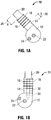
- FIG. 1A a schematic diagram of an exemplary torsional mode transducer having an extended stack to facilitate frequency matching to a horn, in accordance with the present disclosure is presented.
- the torsional mode transducer 10 of FIG. 1A includes a horn 12, a threaded element 14, ceramic rings 16, electrodes 18, a back plate 20, a first sensor 22, and a second sensor 24.
- the length, X, of the back plate 20 is designated as 26 and the length, Y, of the threaded element 14 is designated as 28.
- Transducer 10 permits the generation of either longitudinal vibrations or pure torsional waves.
- Transducer 10 includes a transducer stack, comprising a number of axially polarized PZT ceramic rings 16, separated by silver or gold plated brass electrodes 18 and is compressively attached to a tangential face of the transducer 10 via spigoted back plate 20, with threaded spigot 32 located in tapped hole 34 (as shown in FIG. 1B ).
- FIG. 1A shows at least two piezo-electric sensors, a first sensor 22 and a second sensor 24 located on the horn 12.
- the sensors 22 and 24 are located so that they respond selectively to torsional and longitudinal horn modes.
- the waveform from each piezo-electric sensor 22, 24 will be phase shifted according to the change in torsional displacement from the sensors of the horn where it is at a minimum, to the periphery where it is at a maximum.
- both sensors would experience the same extensional displacement of the horn end face, producing in-phase outputs from said piezo electric sensors.
- the specific operation of sensors 22, 24 will be further described below with reference to FIG. 11 .
- threaded element 14 may be designed to be any length 28.
- the length 28 of the threaded element 14 may be varied based on a plurality of factors, such as, but not limited to, the material of the horn 12 and the natural resonant frequencies of one or more components of the transducer 10 (e.g., horn 12, stack assembly, and/or waveguide 56).
- the threaded element 14 may be varied between a few millimeters up to 20mm depending on the desired application.
- the length 28 of the threaded element 14 affects the output of the horn 12.
- the length 28 of the threaded element 14 may produce a desired vibration or wave (e.g., a torsional wave, a pure torsional wave, a longitudinal wave, a flexural mode wave or a combination of these waves).
- the length 26 of the back plate 20 may be varied between a few millimeters up to 20mm depending on the desired application and may also affect the type of wave produced by the horn 12.
- the length 28 of the threaded element 14 may be in the range of 2-10mm.
- threaded element 14 enables an optimization of the realization of pure torsional mode as the output of the horn 12 and enables an accurate method of fine-tuning a surgical tool/device to a user's desired specifications.
- threaded element 14 may be adjusted prior to assembly or after (subsequently) assembly of the transducer 10 to an external device (e.g., such as a waveguide 56 described below with reference to FIGs. 4 and 5 ).
- threaded element 14 may have a variety of different uniform or non-uniform shapes. The substantially cylindrical shape in the Figures is merely illustrative.
- a drive frequency may be controlled to fine-tune resonance features and excite a desired mode for a surgical tool by adding a threaded element 14 between the horn 12 and the transducer stack of the transducer 10.
- FIG. 1A defines means for varying the stack assembly properties, which in turn define the modal characteristics of the horn 12. The ability to optimize the torsional output from the transducer 10 is enhanced by providing or enabling this tuning facility at each end of the stack assembly.
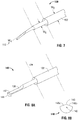
- FIG. 1B a schematic diagram of an exemplary torsional mode transducer having an extended stack with a threaded spigot located in a tapered hole is presented.
- Torsional mode transducer 11 is substantially similar to torsional mode transducer 10 and thus will only be discussed further herein to the extent necessary to identify differences in construction and/or use.
- the torsional mode transducer 11 of FIG. 1B includes a horn 12, a threaded element 14, ceramic rings 16, electrodes 18, a back plate 20, a first sensor 22, and a second sensor 24. Additionally, the transducer 11 includes a threaded spigot 32 located in a tapered hole 34.
- the transducer stack/assembly includes a threaded element 14 inserted between the transducer stack and the horn 12.
- a threaded element 14 inserted between the transducer stack and the horn 12.
- spigot 32 is extended to accommodate attachment of threaded element 14. This feature allows the resonant characteristics of the complete stack incorporating threaded element 14 to be tuned by adjusting the overall length of the transducer stack prior to attachment to the horn 12.
- Threaded element 14 may be either parallel-sided or tapered in section towards its distal end.
- horn 12 is a tapered horn.
- FIG. 1C a schematic diagram of a torsional mode transducer illustrating critical dimensions of the transducer with a circumscribed cylinder from which a major component is machined is presented.
- the torsional mode transducer 13 includes a stack assembly 21 disposed between the back plate 20 and a cylindrical surface 31.
- the stack assembly 21 abuts the cylindrical surface 31 via abutment member 37 mounted on one tangential face created by machining the shaded region of the circumscribing cylindrical surface 31 of FIG. 1C.
- FIG. 1C and FIG. 2 illustrate dimensional definitions transducers 13, 15.
- FIG. 1C defines circumscribing surface 31 which sets a tangential mounting plane of the stack assembly 21.
- a flexural rotation of the stack assembly 21 through angle, ⁇ , (designated as element 44 in FIG. 3 ) generates a torque about the horn axis O, thus driving the horn 12 into a torsional mode.
- FIG. 2 a schematic diagram of an axial view of an exemplary torsional mode transducer is presented.
- the torsional mode transducer 15 includes a threaded hole 34 for waveguide attachment. Additionally, the transducer 15 includes exponential tapering surfaces 36, cylindrical extremity 38, cylindrical isolating flange 33 located adjacent to the horn 12, shaded area 35, and the abutment member 37.
- Horn 12 is machined with exponential tapering surfaces 36 and interrupted by cylindrical isolating flange 33, where the exponential tapering surfaces 36 are cut tangentially to circumscribing cylindrical surface 31 (see Figure 1C ). Moreover, stack assembly 21 (see Figure 1C ) is disposed adjacent to horn 12 so that its cylindrical extremity 38 coincides with an outer extremity of a tangential face of the horn 12 and overlaps an inner extremity as indicated by the shaded area 35.
- FIG. 3 a schematic diagram of a geometric relationship between flexural stack displacement and torsional horn displacement is presented.
- the geometric relationship 40 of FIG. 3 illustrates stack displacement 42 and an angle, ⁇ , designated as 44.
- Transducer 10 having the stack assembly is located on horn 12 so that its cylindrical extremity coincides with the outer extremity of a tangential face of the horn 12.
- the relationship between the stack diameter, d', the proximal horn effective diameter d, and the circumscribed diameter D are chosen critically in order to generate the required vibrational mode and resonant frequency.
- FIG. 3 illustrates the geometry which controls the transfer of stack displacement 42 to the horn 12.
- Critical selection of d'/D ratio for optimum compact transducer operation is defined as 0.45 ⁇ d'/D ⁇ 0.55; preferably, 0.482; and for normal (axial mode stack) operation, 0.3 ⁇ d'/D ⁇ 0.4; preferably 0.333.
- Torsional resonance is established in either case by critical selection of a length of the horn 12, a diameter of connecting member 52 (shown in FIGs. 4 and 5 ) and the dimensions of the waveguide 56 (shown in FIGs. 4 and 5 ).
- FIG. 4 a schematic diagram of an exemplary torsional mode transducer connected to a waveguide with an illustration of the displacement amplitude distribution is presented.
- the transducer/waveguide configuration 50 includes torsional mode transducer 10 described above with reference to FIG. 1A .
- the transducer/waveguide configuration 50 further includes connecting member 52, a first nodal plane 54, waveguide 56, a second nodal plane 58, shroud tube 60, a third nodal plane 62, a fourth nodal plane 64, and an end effector 66.
- the end effector 66 depicts a portion of the waveguide 68 and a distal tip 70.
- Arrow 80 illustrates the torsional movement of the waveguide 56.
- FIG. 4 further depicts a graph 71 illustrating a transmission wave that is generated when the transducer/waveguide configuration 50 is activated.
- a half wavelength 72 is generated between the horn 12 and the connecting member 52.
- a half wavelength 74 is generated between the first nodal plane 54 and the second nodal plane 58.
- a half wavelength 74 is also generated between the last two distal nodes 64 and 62.
- a quarter of a wavelength 76 is generated between the fourth nodal plane 64 and the distal tip 70 of the end effector 66. Note that the mid-section of the waveguide is omitted to save repetition, but may be typically 7 or 8 wavelengths long.
- FIG. 4 further depicts a graph 51 illustrating the effect of stack flexing (as described below).
- the waveguide 56 consists of an integral number of half wavelengths for shear wave propagation at the resonant frequency. Waveguide isolation is achieved by local increase in diameter coincident with nodal planes 54, 58, 62, 64, which create space between the plastic lined shroud tube 60 and active regions of the waveguide 56.
- the waveguide may be referred to as an elongated shaft having a proximal end and a distal end.
- the distal end may be separated into one or more sections.
- the distal end may be separated into three sections.
- the first section may have a first width and a first length
- the second section may have a second width and a second length
- the third section may have a third width and a third length, where the first, second, and third widths are the same or different from each other.
- the first section may refer to an end effector
- the second section may refer to a connecting section
- the third section may refer to a tip portion/blade portion of the distal end of the elongated shaft.
- the end effector may be a curved blade having twin grooves as illustrated in FIG. 4 , element 70.
- FIG. 4A a schematic diagram illustrating a detail of the end effector of the torsional mode transducer of FIG. 4 , in accordance with the present disclosure is presented.
- the detailed view illustrates the shape of the distal tip 70, which depicts a twin groove configuration.
- one skilled in the art could contemplate a plurality of different distal tip configurations to achieve either longitudinal and/or torsional excitation.
- FIG. 5 a schematic diagram of an exemplary longitudinal mode transducer connected to a waveguide with an illustration of the displacement amplitude distribution is presented.
- Transducer 90 is substantially similar to torsional mode transducer 50 and thus will only be discussed further herein to the extent necessary to identify differences in construction and/or use.
- Transducer 90 has a similar transmission wave graph to the transmission wave graph illustrated in FIG. 4 .
- Graph 91 illustrates a transmission wave that is generated when the transducer/waveguide configuration 90 is activated.
- a half wavelength 92 is generated within the horn 12.
- a half wavelength 94 is generated between the first nodal plane 54 and the second nodal plane 58.
- a half wavelength 94 is also generated between the third nodal plane 62 and the fourth nodal plane 64.
- a quarter of a wavelength 96 is generated between the fourth nodal plane 64 and the distal tip 70 of the end effector 66.
- FIG. 5 further depicts a graph 95 illustrating the effect of stack flexing (as described below).
- the transducer stack assembly is activated in a variant flexural mode such that end face 82 of the back plate 20 is deflected as indicated by arrow 84 in a longitudinal direction.
- This stack movement generates a longitudinal mode in the horn 12 at a frequency consistent with compression wave transmission in the horn 12 and attached waveguide 56.
- nodal bosses or nodal planes 54, 58, 62, 64 machined on the waveguide 56 provide a simple means of acoustic isolation of the waveguide 56 from the mounting tube(s) 160, which allow the torsional/longitudinal resonance to be deployed with a cooperative hinged jaw 182 (see FIG. 9 ).
- FIGs. 4 and 5 illustrate the relative effects of two flexural stack modes in orthogonal planes, as shown in graphs 51, 71, 91, 95. Specifically, graphs 51 and 95 illustrate the effect of the stack flexing in the YZ plane which generates a torsional mode in the horn 12 and the waveguide 56. When excited at a different frequency, exciting flexure in the XY plane of FIG. 5 , the output is longitudinal.
- FIGS. 4 and 5 further illustrate the potential to generate two different modes alternately at different frequencies, which are selected to produce torsional and longitudinal wavelengths with a number of coincident nodal planes 54, 58, 62, 64.
- the ability to tune the stack assembly allows one skilled in the art to optimize either longitudinal or torsional outputs and also to combine them with an appropriate switched, dual frequency electrical generator (as described below with reference to FIGs. 11 and 12 ).
- the stack assembly and the horn 12 determine the mode of vibration and the waveguide 56 is tuned to resonate in a particular mode by adjusting its length to encompass a number of half wavelengths at one or more designated frequencies.
- graph 51 shows a stack mode which generates a rotational mode in the horn 12, creating torsional resonance in the waveguide 56, indicated by arrows 71 and 80.
- the horn 12 always embodies a half wave length with antinodes at both ends.
- FIGs. 4 and 5 both serve to illustrate the relationship between the stack flexural mode (plane XY longitudinal and YZ torsional) and the waveguide mode.
- FIG. 4 illustrates a torsional system
- FIG. 5 illustrates a longitudinal system.
- the only difference in the waveguide 56 is that the compression half wave length is greater than the torsional since compression wave velocity is greater than shear velocity for a given material.
- FIGs. 6 and 7 It is one objective of the embodiments of the invention illustrated in FIGs. 6 and 7 to create a torsional mode curved end effector 100, 130 with a full distal focusing feature. FIGs. 6 and 7 will be simultaneously described.
- FIG. 6 illustrates curved end effector 100 in accordance with the present invention, which comprises three distal waveguide regions; a proximal first portion 102 of section W o , which would attach to a torsional waveguide and transducer as defined in FIG. 4 ; a half wavelength second distal section extending from nodal isolating boss 122, through quarter wave anti-nodal step 124 to first distal nodal step, 126 of section W s ; and a third distal quarter wavelength region extending from distal step 126 to torsional blade tip 128 of section W l .
- the third section embodies a double grooved focusing region 114, similar to that illustrated in FIG. 4A and defining the extent of the distal blade.
- the end effector waveform is shown schematically as 101 in FIG. 6 , where the second effector region of length Z 120, is shown to be a half wavelength, with initial length X, 116, terminating in anti-nodal step 124.
- the anti-nodal step has a zero amplitude gain characteristic which in conjunction with nodal gain step 126 permits control of the critical torsional displacement amplitude within curved blade region 114.
- the magnitude of the waveguide section steps at 124, 126 and any non-linear variation in the section along Y, 118, in FIG. 6 can clearly be varied independently to control the output characteristics of the waveguide, allowing high rotational amplitudes with minimum harmful transverse modes. It is noted that the above expressions serve as an exemplary definition only and do not limit scope for wider application of the present disclosure.
- FIGs. 8A and 8B are schematic illustrations of a further aspect of the present disclosure intended to optimize the use and effectiveness of the torsional mode transducer, waveguide, and end effector system referred to throughout the present disclosure, in a particular surgical process which involves tissue welding as an end point objective.
- the elements of the end effector structure which focus energy into the target tissue for example a specific large blood vessel, are emphasized whilst at the same time changing the detail of features which encourage tissue separation in order to delay or prevent that process.
- FIG. 8A shows a welder end effector 140 attached to waveguide 142 at nodal step plane 134.
- the section change at said nodal step creates sufficient torsional amplitude gain, according to the principles described earlier, to enable the tissue contacting face 136 to direct energy into the target vascular tissue.
- FIG. 8B shows an example of a suitable profile of end effector blade 136 which is essentially flat but may be raised centrally as shown, creating angled faces 148a and 148b which meet at ridge feature 145.
- Surface 36 may be close to the diametral plane of the end effector, defined by waveguide axis 146 in FIG. 8B .
- the displacement amplitude of the torsional mode activation in faces 148a and 148b is maximum at the periphery and small along the central ridge 145. This characteristic generates focused ultrasound transmission into contacting tissue either side of said ridge creating a strong weld.
- the low energy associated with ridge 145 produces only a slow tissue separation effect delaying cutting and ensuring a fully haemostatic tissue bond in the target vessel adjacent to facets 148a and 148b.
- Cutting is further slowed by employing a pulse mode electrical drive to the torsional transducers.
- the generator is described with reference to FIGs. 11 and 12 below.
- the operation of ultrasonically activated dissectors and welders such as described above is greatly enhanced by the provision of a hinged cooperative jaw attached to a protective shroud which also houses a jaw articulation system. This is more fully illustrated by reference to FIGs. 9 and 10 below.
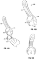
- FIG. 9 a schematic diagram of a waveguide, shroud, and hinged jaw of a torsional mode waveguide configuration, embodying the present invention, is presented.
- the torsional mode waveguide configuration 150 includes one or more liners 152, a separating member 154, a waveguide axis 156, a waveguide 158, a concentric tube 160, a locking member 162, an axial view of spigot(s) 164, a socket balls 166, an outer surface 168, a tube edge 170, a gap 172, a top portion 174 of jaw 182, a clamping feature 176, a first inner portion 178 of jaw 182, and a second inner portion 180 of jaw 182.
- FIGs. 9 , 10A, 10B, and 10C a torsional mode dissector head incorporating a waveguide, a co-operative jaw, a protective outer casing and an acoustic isolation system is described.
- FIG. 9 depicts a distal portion of an ultrasonic tissue dissector.
- Jaw 182 is attached permanently to the socket balls 166 and the clamping feature 176, thus allowing the jaw 182 to rotate in a plane which is parallel to the waveguide axis 156.
- the present disclosure permits jaw 182 to be removably mounted to the socket balls 166, being supported on spigots 164, which engage in the locking member 162. Attachment of the jaw 182 is achieved by expanding gap 172 until the separation of the spigots 164 is sufficient to allow them to engage in the locking member 162 having socket balls 166.
- torsional mode waveguide configuration 150 over traditional art is the method of acoustic isolation of the waveguide 158 from the passive elements of the system, represented by concentric tube 160 and one or more liners 152.
- FIGs. 10A, 10B, and 10C schematic diagrams of the jaw configuration, in accordance with the present disclosure are presented.
- Jaw configuration 200 is substantially similar to the jaw portion 184 of FIG. 9 and thus will only be discussed further herein to the extent necessary to identify differences in construction and/or use. Jaw configuration 200 further includes a pair of pivot members 202 and a pair of receiving members 204.
- FIG. 10A merely illustrate how the pivot members 202 fasten to the receiving members 204 of FIG. 10B.
- FIG. 10C merely illustrates how the gap 172 separates the ends of the jaw configuration 200 in order to provide a linking mechanism between the spigot 164, the socket balls 166 and the locking member 162.
- FIG. 11 a block diagram of a first example of control and power circuits for a torsional mode ultrasonic generator, in accordance with the present disclosure is presented.
- the block diagram 220 includes first isolation blocks module 222, signal conditioning module 224, digitization module 226, software algorithms module 228, DDS signal generator module 230, power amplifier module 232, second isolation blocks module 234, current sensor module 250, power sensor module 260, and amplitude sensor module 270.
- the current sensor module 250, the power sensor module 260, and the amplitude sensor module 270 may be collectively referred to as an output transducer 240.
- an electrical generator has the capability of driving torsional mode systems, such as the ones described in FIGs. 1-8 .
- a processor controlled DDS (direct digital synthesis) chip 230 may drive a switch mode power amplifier 232 coupled to a torsional mode transducer 240 through transformer and impedance matching inductors 250, 260, 270.
- the matching circuit incorporating current and voltage monitoring components and including appropriate isolating circuitry 222, 234, is shown in FIG. 11 .
- the output signals from the current and displacement monitoring circuits 250, 260, 270 are compared during a broad frequency scan.
- Transducer displacement amplitude 270 is monitored using piezo ceramic sensors 5 and 6 mounted on the horn 12, as shown in FIGs. 1 and 2 .
- the signal from sensor 22, positioned on the horn axis, uniquely gives a minimum output when the transducer is a torsional resonance.
- the output from sensor 24 is a maximum at torsional resonance.
- the outputs from each sensor 22, 24 would be at a maximum when the horn 12 is at a longitudinal resonance.
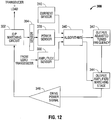
- FIG. 12 a block diagram of a second example of control and power circuits for a torsional mode ultrasonic generator, in accordance with the present disclosure is presented.
- the block diagram 300 includes an output transducer 302, a sensor 304, a current sensor 310, a power sensor 320, an amplitude sensor 330, algorithms 340, a first output 342, a second output 344, and a drive power signal 346.
- this second embodiment of the control and power circuits for the torsional mode ultrasonic generator 300 mirrors the transducer current variation as the generator frequency passes through torsional resonance. By comparing these traces it is therefore possible to detect torsional resonance with absolute certainty.
- either current amplitude signals can be used as a means of effecting resonance control.
- a tuning algorithm may then be written to select resonance coincident with maximum power and control loop algorithms may be written for coarse and fine tuning characteristics.
- FIG. 13 a schematic diagram of an alternative example of a torsional mode transducer having an extended stack with two threaded spigots, one located at a proximal end and one located at a distal end of a threaded shaft, in accordance with the present disclosure is presented.
- Torsional mode transducer 400 is substantially similar to torsional mode transducer 11 of FIG. 2 and thus will only be discussed further herein to the extent necessary to identify differences in construction and/or use.
- the torsional mode transducer 400 of FIG. 13 includes a horn 12, a threaded element 14, ceramic rings 16, electrodes 18, a back plate 20, a first sensor 22, and a second sensor 24.
- the transducer 400 further includes a threaded spigot 32 located in a tapered hole 34. Additionally, and in contrast to FIG. 2 , the transducer 400 includes a second threaded spigot 410 on the distal end of the threaded shaft 420.
- the threaded shaft 420 is provided with tightenable spigots 32, 410 (or nuts) at both its proximal and its distal end. This allows the stack assembly to be compressed further while still mounted to the horn 12. Also, one may use exchangeable spigots/nuts 32, 410 at the free end of the stack assembly, having different sizes and masses, the variation in mass allowing one to tune the resonant frequency produced by the stack assembly. In existing stacks, one merely builds a stack, and then checks what frequency it happens to produce and tuning can be carried out by exchanging the spigot/nut 32, but this is less convenient because one needs to separate the stack assembly from the horn 12 to access the nut 32. In contrast, having a threaded shaft 420 with opposing spigots 32, 410 allows for more versatility in assembly and manufacturing.
- fine-tuning resonance requires more critically refined generator circuitry and tuning algorithms capable of differentiating between sharply defined resonance features.
- the exemplary examples provide for efficient fine-tuning of resonance characteristics of one or more components of a surgical tool in order to selectively provide for pure torsional vibrations/waves and/or longitudinal vibrations/waves and/or flexural vibrations/waves.
- transducer/waveguide arrangements described herein can be used in connection in a wide variety of applications outside the implementations described herein.
- the transducer/waveguide arrangements described herein can be used in cooperation with other known transducer/waveguide arrangements.
- the transducer/waveguide arrangements described herein can also be useful for non-human applications.
- the present disclosure also includes as an additional example a computer-readable medium which stores programmable instructions configured for being executed by at least one processor for performing the methods described herein according to the present disclosure.
- the computer-readable medium can include flash memory, CD-ROM, a hard drive, etc.
Landscapes
- Health & Medical Sciences (AREA)
- Surgery (AREA)
- Engineering & Computer Science (AREA)
- Life Sciences & Earth Sciences (AREA)
- Heart & Thoracic Surgery (AREA)
- Animal Behavior & Ethology (AREA)
- Mechanical Engineering (AREA)
- Biomedical Technology (AREA)
- Dentistry (AREA)
- Medical Informatics (AREA)
- Molecular Biology (AREA)
- Nuclear Medicine, Radiotherapy & Molecular Imaging (AREA)
- General Health & Medical Sciences (AREA)
- Public Health (AREA)
- Veterinary Medicine (AREA)
- Surgical Instruments (AREA)
- Apparatuses For Generation Of Mechanical Vibrations (AREA)
- Transducers For Ultrasonic Waves (AREA)
Description
- This present invention relates to a surgical tool adapted to cut and/or cauterize tissue by utilizing an ultrasonically vibrated blade or other end-effector of the surgical tool. More particularly but not exclusively, it relates to a tool having an end-effector adapted to direct ultrasonic energy controllably into selected tissues.
- In the past few decades, considerable interest has been directed toward the use of ultrasonically activated blades and shears for the dissection, cutting, and welding of soft tissue.
- It is known to cut tissue by means of ultrasonically vibrated knives or scalpels. When a scalpel cuts tissue its effectiveness is indicated by the cutting force. This derives from the pressure required to separate the structure and from the frictional drag as the blade is drawn between the cut sections. Vibrating the blade can reduce friction and may also reduce the bond strength of the tissue. Both objectives could be achieved by applying vibrations to the cutting blade in either a longitudinal or a torsional mode.
- Haemostatic cutting of individual vessels and well vasculated tissue has been taught by
U.S. Patents US 3,636,943 andUS 3,862,630 . In the '943 and '630 patents, the use of ultrasonic energy in the form of mechanical vibrations is transmitted by a tool member to close off small severed blood vessels, such as in humans, by the formation of closures at the terminal portions thereof, and stop what is referred to as "ooze," that requires constant mopping or cleansing techniques during an operation. Such tool member may be in the form of a knife ultrasonically vibrated to simultaneously sever and close off respective terminal portions of the severed blood vessels while performing surgical procedures. The tool member, of a proper configuration, may also join together layers of tissue, including the walls of unsevered blood vessels, and with respect to the latter is foreseen as replacing the "tying off" of arteries and veins currently necessary in surgery. Thus, these patents use a longitudinal mode system to activate a blade, which has roughened surfaces in order to increase frictional energy transfer during the cutting of vascular tissue. - Additionally,
U.S. Patents US 5,322,055 andUS 6,283,981 disclose oscillatory systems with the addition of hinged passive elements designed to press the target tissue against an energized blade so as to increase the frictional drag of tissue on the blade, and, thus, increase the heating effect necessary to ensure coagulation during the cutting process. - The
US 5,322,055 patent relates to an ultrasonic surgical apparatus that includes a surgical instrument having a hand piece with a transducer for converting an electrical signal into longitudinal vibratory motion of a blade connected to the hand piece and an accessory releasably connected to the hand piece to enable clamping of tissue against the vibrating blade to afford improved coagulating and cutting of tissue. Scissors-like grips actuate a pivoted clamp jaw along one side of the ultrasonically vibrating blade to compress and bias tissue against the blade in a direction normal to the direction of longitudinal vibratory movement. The clamp jaw and blade are rotatable relative to one another to align a selected blade edge of a multi-edged blade with the clamp jaw for cutting and coagulating while clamping or circumferentially spacing a selected blade edge from the clamp jaw for cutting and coagulating without clamping. - The
US 6,283,981 patent relates to a method of designing a balanced ultrasonic surgical instrument including an ultrasonic transmission rod and an asymmetric ultrasonically actuated blade attached to the distal end of the ultrasonic transmission rod. The ultrasonically actuated blade includes a treatment portion. The treatment portion has a functional feature such as, for example, a curved blade which makes the treatment portion asymmetric. In such method, a balance portion including at least a first asymmetric balance feature is designed and positioned between the ultrasonically actuated blade and the ultrasonic transmission rod to balance out any undesirable torque generated by the treatment portion. - All of the above-described systems share the common principle of frictionally generated heating, related to cyclic vector reversal at the friction interface, to ensure that coagulation occurs simultaneously with tissue separation. In such systems, the frictionally generated heating principle is described in terms of longitudinal excitation of the cutting blade. However, pure longitudinal excitation is not the most efficient manner to transfer vibrational energy into soft tissue.
- Moreover, in
U.S. Patent US 6,425,906 andGB 2,371,492 - For example, the
US 6,425,906 patent relates to a surgical tool for cutting and/or coagulating tissue that includes a piezo-electric driver to generate ultrasonic energy including torsional mode vibrations. The '906 patent also relates to a distal torsional mode end effector, which creates focused energy transmission into target tissue trapped by a hinged jaw element against an activated waveguide. - In the
GB 2,333,709 GB 2,371,492 GB 2,371,492 -
EP 0 970 660 A1 discloses an ultrasonic surgical tool according to the preamble of claim 1, the preamble of claim 1 is based on this document. Additionally, alsoUS 4,922,902 shows a surgical tool with features of the preamble of claim 1 - Thus, while it is known to use torsional excitation to transfer vibrational energy into soft tissue, it is still desirable to produce further surgical tools that effectively manipulate torsional mode excitation.
- The invention is disclosed in independent claim 1 with preferred embodiments disclosed in the dependent claims.
- It is hence an object of the present invention to provide surgical tools employing torsional mode ultrasonic vibrations that obviate the above problems, and in particular allow more controllable and effective application of the benefits of torsional mode vibrations.
- According to a first aspect of the present invention, there is provided a surgical tool comprising elongate waveguide means operatively connected or connectable at a proximal end to a means of generating ultrasonic vibrations and provided adjacent a distal end with an operative element, wherein the waveguide means has a first diameter and the operative element comprises an elongate effector element having a second diameter less than the first, a proximal end of the effector element defining a first step junction located substantially in a nodal plane of ultrasonic vibrations generated in the waveguide means.
- The operative element comprises an elongate intermediate portion extending between the waveguide means and the effector means and having a third diameter intermediate between the first and second diameters, said intermediate portion defining said first step junction with the effector means at its distal end and defining a second step junction with the waveguide means at its proximal end.
- Preferably, a distal end of the effector element is located at an antinodal plane of the ultrasonic vibrations.
- The second step junction is preferably located substantially at an antinodal plane of the ultrasonic vibrations in the waveguide means.
- The intermediate portion may have a length substantially corresponding to a quarter of the wavelength of the ultrasonic vibrations therein.
- The effector element may have a length substantially corresponding to a quarter of a wavelength of the ultrasonic vibrations therein.
- The second diameter of the effector element may be between one-third and two-thirds of the first diameter of the waveguide means.
- A ratio of diameters either side of the first step junction may be selected to produce a desired velocity amplitude gain across the junction, said gain being dependent on the cube of said ratio of diameters.
- Advantageously, the waveguide means and the intermediate portion extend coaxially.
- The effector element may extend coaxially with the waveguide means.
- Alternatively, at least part of the effector element may extend in a curve away from a longitudinal axis of the waveguide means.
- Preferably, a distal tip of the effector element is then disposed within an envelope having said first diameter and extending coaxially from the waveguide means.
- The effector element may have said second diameter substantially along its entire extent.
- Alternatively, the effector element may have said second diameter adjacent the first step junction but vary in diameter towards its distal end.
- The effector element may lessen in diameter towards its distal end.
- Preferably, the means to generate ultrasonic vibrations produces torsional mode ultrasonic vibrations in the waveguide means and the effector element.
- The means to generate ultrasonic vibrations may be tuned to produce a desired resonant vibration in the waveguide means and effector element.
- The means to generate ultrasonic vibrations may be driven by pulse mode electrical drive means.
- The effector element may be so profiled as to minimize non-torsional mode vibrations therein.
- The effector element may be so configured as to minimize its moment of inertia about a longitudinal axis of the waveguide means.
- The waveguide means may be provided with a plurality of radially outstanding spacer bosses located at nodal planes of the ultrasonic vibrations produced therein.
- The first step junction may then be located at a separation of a half wavelength of said vibrations from a most distal of said spacer bosses.
- The second step junction may be located at a separation of a quarter wavelength of said vibrations away from a most distal of said spacer bosses.
- The operative element may comprise a non-vibratable jaw member, selectably operable to hold a desired zone of tissue in contact with the ultrasonically-vibratable effector element.
- In a first embodiment of the invention, the effector element is provided with an adjacent pair of elongate groove means extending proximally from its distal end and defining between them elongate ridge means.
- Preferably, said groove means extend along a curved distal portion of the effector element.
- Advantageously, said groove means have a generally part-circular cross-sectional profile.
- Said groove means may be adapted to focus ultrasonic energy into adjacent tissue, so as to weld or coagulate said tissue.
- The ridge means may be adapted to sever tissue brought into contact therewith.
- In a second embodiment, the effector element is provided with an elongate generally flat operative face extending substantially parallelly to an axis of the effector element.
- Said operative face may comprise two substantially planar facets meeting along a shallow longitudinal ridge.
- An angle between the planes of said facets may be less than 45°, optionally less than 30°, ideally less than 15°.
- Each outer edge of the operative face may be beveled.
- The operative face may be adapted to transmit ultrasonic energy into tissue contacting or held against the face so as to weld or coagulate said tissue in preference to separating the tissue.
- There is provided an exemplary method of treating tissue, not forming part of the invention, comprising providing a tool as described in the first aspect above, bringing an effector element thereof into contact with the tissue to be treated and vibrating the tool ultrasonically so as to effect the exemplary treatment.
- The exemplary treatment may comprise severing or separating said tissue.
- The exemplary treatment may comprise coagulating or welding said tissue.
- In an example not forming part of the claimed invention, an exemplary transducer is presented including a horn having a first diameter; a threaded element having a second diameter; a transducer stack having a third diameter and including a plurality of rings; and a back plate positioned adjacent to the transducer stack; wherein the threaded element is positioned between the horn and the transducer stack to selectively enable torsional tuning adjustments of the transducer.
- In another example not forming part of the claimed invention, an exemplary method for tuning a transducer is presented including positioning a threaded element between a horn and a transducer stack; and selectively enabling torsional tuning adjustments of the transducer based on the positioning of the threaded element; wherein the horn has a first diameter, the threaded element has a second diameter, the transducer stack has a third diameter, includes a plurality of rings, and is positioned adjacent to a back plate.
- In example not forming part of the claimed invention, an exemplary method for manufacturing a transducer is presented including positioning a threaded element between a horn and a transducer stack; and selectively enabling torsional tuning adjustments of the transducer based on the positioning of the threaded element; wherein the horn has a first diameter, the threaded element has a second diameter, the transducer stack has a third diameter, includes a plurality of rings, and is positioned adjacent to a back plate.
- Embodiments of the present invention will now be more particularly described by way of example and with reference to the Figures of the accompanying drawings, in which:
-
Figure 1A is a schematic diagram of exemplary torsional mode transducer having an extended stack to facilitate frequency matching to a horn, -
Figure 1B is a schematic diagram of an exemplary torsional mode transducer having an extended stack with a threaded spigot located in a tapered hole, -
Figure 1C is a schematic diagram of an exemplary torsional mode transducer illustrating critical dimensions of the transducer with a circumscribed cylinder from which a major component is machined; -
Figure 2 is a schematic diagram of an axial view of an exemplary torsional mode transducer. -
Figure 3 is a schematic diagram of a geometric relationship between flexural stack displacement and torsional horn displacement, -
Figure 4 is a schematic diagram of an exemplary torsional mode transducer connected to a waveguide with an illustration of the displacement amplitude distribution, -
Figure 4A is a schematic diagram illustrating a detail of the end effector of the torsional mode transducer ofFIG. 4 , -
Figure 5 is a schematic diagram of an exemplary longitudinal mode transducer connected to a waveguide with an illustration of the displacement amplitude distribution, -
Figure 6 is a schematic diagram of an axial view of a curved end effector in a torsional mode waveguide configuration, embodying the present invention; -
Figure 7 is an isometric schematic diagram of a curved end effector in a torsional mode waveguide configuration shown inFIG. 6 , embodying the present invention; -
Figure 8A is an isometric schematic diagram of a welder end effector in a torsional mode waveguide configuration, embodying the present invention; -
Figure 8B is a frontal elevation of a distal end of a further end-effector embodying the present invention; -
Figure 9 is a schematic diagram of a waveguide, shroud, and hinged jaw of a torsional mode waveguide configuration, embodying the present invention; -
Figures 10A, 10B, and 10C are schematic diagrams of the configuration of the jaw ofFigure 9 , embodying the present invention; -
Figure 11 is a block diagram of a first example of control and power circuits for a torsional mode ultrasonic generator, -
Figure 12 is a block diagram of a second example of control and power circuits for a torsional mode ultrasonic generator, and -
Figure 13 is a schematic diagram of an alternative example of a torsional mode transducer having an extended stack with two threaded spigots, one located at a proximal end and one located at a distal end of a threaded shaft. - Referring now to the drawing figures, a system and method for cutting tissue by using torsional mode excitation in accordance with the present disclosure will now be described in detail.
- While embodiments of the present disclosure are susceptible to various modifications and alternative constructions, certain illustrated embodiments thereof have been shown in the drawings and will be described below in detail. It should be understood, however, that there is no intention to limit the embodiments of the present disclosure to the specific form disclosed, but, on the contrary, the embodiments are intended to cover all modifications, alternative constructions, and equivalents falling within the scope of the present disclosure as defined in the claims.
- The present disclosure may be understood more readily by reference to the following detailed description of the disclosure taken in connection with the accompanying drawing figures, which form a part of this disclosure. It is to be understood that the disclosure herein is not limited to the specific devices, methods, conditions or parameters described and/or shown herein, and that the terminology used herein is for the purpose of describing particular embodiments by way of example only and is not intended to be limiting of the claimed subject matter.
- The present disclosure proposes utilizing torsional ultrasound for efficiently transferring vibrational energy into soft tissue. Unlike any other ultrasonic tools, the surgical tool of the exemplary embodiments directs powerful compression energy into the target tissue, resulting in secure coagulation and fast cutting. Away from these compression grooves, only relatively less efficient frictional energy is present. This is minimized further through a fine polishing process that reduces the risk of transferring unwanted energy into vital structures and significantly reduces the likelihood of fatigue failure with low gain. The surgical tools of the exemplary embodiments direct compression energy into the target tissue. Energy is transferred quickly, denaturing the tissue protein and rapidly forming a coagulum. At the same time the central blade cuts through the tissue as the jaw of the surgical tool is closed. The result is fast and efficient haemostatic cutting.
- The present disclosure further proposes emphasizing the fundamental advantages of torsional mode systems over conventional longitudinal extensional devices. The present disclosure further addresses the characteristics of torsional dissector systems that introduce particular opening issues.
- For instance, torsional mode transmission has several advantages over longitudinal mode transmission. These include, but are not limited to the following: the motional gain associated with cross sectional changes is greater in shear wave transmission than in equivalent compression wave transmission. Analysis of torsional mode concentrators reveals a gain dependence on moments of inertia associated with section changes along the transforming element. In contrast, compression wave transmission is related to linear force variation which changes with sectional area. This consideration leads to the motional gain expression for a longitudinal mode stepped transformer, defined as the square of the diameter ratio between input and output sections, and for the shear wave equivalent, the third power of the diameter ratio. This characteristic is consistent with increased Q and impedance transformation ratio for shear wave systems relative to compression wave equivalents. Thus, tuning to resonance requires more critically refined generator circuitry and tuning algorithms capable of differentiating between sharply defined resonance features.
- Another distinguishing feature between longitudinal and torsional mode systems relates to transducer design. Transducer designs are specific to particular modes. The classic Langevin sandwich transducer is conventionally used to generate and sustain compression waves in a longitudinal mode system. In contrast, a mode converting horn with tangentially attached transducer stack is configured to generate a torsional output from the narrow end of the horn. The transducer stack is driven in a selected flexural mode to generate a torsional mode in the horn. Alternative flexural stack modes result in a substantially longitudinal output from the mode converter. As a result, in each case pure torsional or longitudinal modes depend on the design of the waveguide attached at the output of the horn. Operating frequencies generally result in overtone modes with waveguides spanning several wavelengths. The relationship between the horn and transducer stack renders the oscillatory system susceptible to complex transverse modes occurring in the horn and waveguide assembly. Careful and accurate control of the drive frequency is required to excite the correct mode and lock the correct mode by the generator frequency/mode control circuitry. The exemplary embodiments described below illustrate how to control a drive frequency to fine-tune resonance features and excite a desired mode for a surgical tool.
- Embodiments and examples will be described below while referencing the accompanying figures. The accompanying figures are merely examples and are not intended to limit the scope of the present disclosure.
- Referring to
FIG. 1A , a schematic diagram of an exemplary torsional mode transducer having an extended stack to facilitate frequency matching to a horn, in accordance with the present disclosure is presented.
Thetorsional mode transducer 10 ofFIG. 1A includes ahorn 12, a threadedelement 14, ceramic rings 16,electrodes 18, aback plate 20, afirst sensor 22, and asecond sensor 24. The length, X, of theback plate 20 is designated as 26 and the length, Y, of the threadedelement 14 is designated as 28. - In an example, the
transducer 10 permits the generation of either longitudinal vibrations or pure torsional waves.Transducer 10 includes a transducer stack, comprising a number of axially polarized PZT ceramic rings 16, separated by silver or gold platedbrass electrodes 18 and is compressively attached to a tangential face of thetransducer 10 viaspigoted back plate 20, with threadedspigot 32 located in tapped hole 34 (as shown inFIG. 1B ). - Moreover,
FIG. 1A shows at least two piezo-electric sensors, afirst sensor 22 and asecond sensor 24 located on thehorn 12. Thesensors electric sensor sensors FIG. 11 . - Furthermore, threaded
element 14 may be designed to be anylength 28. Thelength 28 of the threadedelement 14 may be varied based on a plurality of factors, such as, but not limited to, the material of thehorn 12 and the natural resonant frequencies of one or more components of the transducer 10 (e.g.,horn 12, stack assembly, and/or waveguide 56). The threadedelement 14 may be varied between a few millimeters up to 20mm depending on the desired application. Thelength 28 of the threadedelement 14 affects the output of thehorn 12. In other words, by varying thelength 28 of the threadedelement 14 one skilled in the art may produce a desired vibration or wave (e.g., a torsional wave, a pure torsional wave, a longitudinal wave, a flexural mode wave or a combination of these waves). Additionally, thelength 26 of theback plate 20 may be varied between a few millimeters up to 20mm depending on the desired application and may also affect the type of wave produced by thehorn 12. Preferably, the smaller thelength 28 of the threadedelement 14, the better the achievement of the desired excitation or mode. For example, thelength 28 of the threadedelement 14 may be in the range of 2-10mm. - Once again, the insertion of the threaded
element 14 enables an optimization of the realization of pure torsional mode as the output of thehorn 12 and enables an accurate method of fine-tuning a surgical tool/device to a user's desired specifications. Also, threadedelement 14 may be adjusted prior to assembly or after (subsequently) assembly of thetransducer 10 to an external device (e.g., such as awaveguide 56 described below with reference toFIGs. 4 and5 ). Also, threadedelement 14 may have a variety of different uniform or non-uniform shapes. The substantially cylindrical shape in the Figures is merely illustrative. - Thus, in accordance to
FIG. 1A , a drive frequency may be controlled to fine-tune resonance features and excite a desired mode for a surgical tool by adding a threadedelement 14 between thehorn 12 and the transducer stack of thetransducer 10. Additionally,FIG. 1A defines means for varying the stack assembly properties, which in turn define the modal characteristics of thehorn 12. The ability to optimize the torsional output from thetransducer 10 is enhanced by providing or enabling this tuning facility at each end of the stack assembly. - Referring to
FIG. 1B , a schematic diagram of an exemplary torsional mode transducer having an extended stack with a threaded spigot located in a tapered hole is presented. -
Torsional mode transducer 11 is substantially similar totorsional mode transducer 10 and thus will only be discussed further herein to the extent necessary to identify differences in construction and/or use. Thetorsional mode transducer 11 ofFIG. 1B includes ahorn 12, a threadedelement 14, ceramic rings 16,electrodes 18, aback plate 20, afirst sensor 22, and asecond sensor 24. Additionally, thetransducer 11 includes a threadedspigot 32 located in a taperedhole 34. - As shown in
FIG. 1A , the transducer stack/assembly includes a threadedelement 14 inserted between the transducer stack and thehorn 12. As shown inFIG. 1B , to facilitate attachment of the threadedelement 14 to thehorn 12,spigot 32 is extended to accommodate attachment of threadedelement 14. This feature allows the resonant characteristics of the complete stack incorporating threadedelement 14 to be tuned by adjusting the overall length of the transducer stack prior to attachment to thehorn 12. Threadedelement 14 may be either parallel-sided or tapered in section towards its distal end. Preferably horn 12 is a tapered horn. - Referring to
FIG. 1C , a schematic diagram of a torsional mode transducer illustrating critical dimensions of the transducer with a circumscribed cylinder from which a major component is machined is presented. - The
torsional mode transducer 13 includes astack assembly 21 disposed between theback plate 20 and acylindrical surface 31. Thestack assembly 21 abuts thecylindrical surface 31 viaabutment member 37 mounted on one tangential face created by machining the shaded region of the circumscribingcylindrical surface 31 ofFIG. 1C. FIG. 1C and FIG. 2 (described below) illustratedimensional definitions transducers FIG. 1C defines circumscribingsurface 31 which sets a tangential mounting plane of thestack assembly 21. A flexural rotation of thestack assembly 21 through angle, θ, (designated aselement 44 inFIG. 3 ), generates a torque about the horn axis O, thus driving thehorn 12 into a torsional mode. - Referring to
FIG. 2 , a schematic diagram of an axial view of an exemplary torsional mode transducer is presented. - The
torsional mode transducer 15 includes a threadedhole 34 for waveguide attachment. Additionally, thetransducer 15 includes exponential tapering surfaces 36,cylindrical extremity 38, cylindrical isolatingflange 33 located adjacent to thehorn 12, shadedarea 35, and theabutment member 37. -
Horn 12 is machined with exponential tapering surfaces 36 and interrupted by cylindrical isolatingflange 33, where the exponential tapering surfaces 36 are cut tangentially to circumscribing cylindrical surface 31 (seeFigure 1C ). Moreover, stack assembly 21 (seeFigure 1C ) is disposed adjacent to horn 12 so that itscylindrical extremity 38 coincides with an outer extremity of a tangential face of thehorn 12 and overlaps an inner extremity as indicated by the shadedarea 35. - Referring to
FIG. 3 , a schematic diagram of a geometric relationship between flexural stack displacement and torsional horn displacement is presented. - The
geometric relationship 40 ofFIG. 3 illustratesstack displacement 42 and an angle, θ, designated as 44. -
Transducer 10 having the stack assembly is located onhorn 12 so that its cylindrical extremity coincides with the outer extremity of a tangential face of thehorn 12. The relationship between the stack diameter, d', the proximal horn effective diameter d, and the circumscribed diameter D are chosen critically in order to generate the required vibrational mode and resonant frequency. - Rotational movement of the proximal horn mass is initiated by a flexural mode displacement within the stack assembly as illustrated in
FIG. 3 . This mode is possible when d'>d/2, allowing for a more compact transducer design than employing a conventional axial mode stack where d'«d/2.FIG. 3 illustrates the geometry which controls the transfer ofstack displacement 42 to thehorn 12. The equation defining the resolved component of flexural displacement FT, at angle θ, 44, to mounting plane, is given as: T=FT cos θ. ℓ = ½ FT cos (arctan ((d-d')/d)). (d2 + (d-d')2)1/2. - Critical selection of d'/D ratio for optimum compact transducer operation is defined as 0.45 < d'/D<0.55; preferably, 0.482; and for normal (axial mode stack) operation, 0.3 < d'/D<0.4; preferably 0.333. Torsional resonance is established in either case by critical selection of a length of the
horn 12, a diameter of connecting member 52 (shown inFIGs. 4 and5 ) and the dimensions of the waveguide 56 (shown inFIGs. 4 and5 ). - Referring to
FIG. 4 , a schematic diagram of an exemplary torsional mode transducer connected to a waveguide with an illustration of the displacement amplitude distribution is presented. - The transducer/
waveguide configuration 50 includestorsional mode transducer 10 described above with reference toFIG. 1A . The transducer/waveguide configuration 50 further includes connectingmember 52, a firstnodal plane 54,waveguide 56, a secondnodal plane 58,shroud tube 60, a thirdnodal plane 62, a fourthnodal plane 64, and anend effector 66. Theend effector 66 depicts a portion of thewaveguide 68 and adistal tip 70.Arrow 80 illustrates the torsional movement of thewaveguide 56. -
FIG. 4 further depicts agraph 71 illustrating a transmission wave that is generated when the transducer/waveguide configuration 50 is activated. Ahalf wavelength 72 is generated between thehorn 12 and the connectingmember 52. Ahalf wavelength 74 is generated between the firstnodal plane 54 and the secondnodal plane 58. Ahalf wavelength 74 is also generated between the last twodistal nodes wavelength 76 is generated between the fourthnodal plane 64 and thedistal tip 70 of theend effector 66. Note that the mid-section of the waveguide is omitted to save repetition, but may be typically 7 or 8 wavelengths long.FIG. 4 further depicts agraph 51 illustrating the effect of stack flexing (as described below). - Additionally, the
waveguide 56 consists of an integral number of half wavelengths for shear wave propagation at the resonant frequency. Waveguide isolation is achieved by local increase in diameter coincident withnodal planes shroud tube 60 and active regions of thewaveguide 56. - Moreover, the waveguide may be referred to as an elongated shaft having a proximal end and a distal end. In addition, the distal end may be separated into one or more sections. For example, with respect to
FIGs. 6-8B , the distal end may be separated into three sections. The first section may have a first width and a first length, the second section may have a second width and a second length, and the third section may have a third width and a third length, where the first, second, and third widths are the same or different from each other. The first section may refer to an end effector, the second section may refer to a connecting section, and the third section may refer to a tip portion/blade portion of the distal end of the elongated shaft. The end effector may be a curved blade having twin grooves as illustrated inFIG. 4 ,element 70. - Referring to
FIG. 4A , a schematic diagram illustrating a detail of the end effector of the torsional mode transducer ofFIG. 4 , in accordance with the present disclosure is presented. The detailed view illustrates the shape of thedistal tip 70, which depicts a twin groove configuration. Of course, one skilled in the art could contemplate a plurality of different distal tip configurations to achieve either longitudinal and/or torsional excitation. - Referring to
FIG. 5 , a schematic diagram of an exemplary longitudinal mode transducer connected to a waveguide with an illustration of the displacement amplitude distribution is presented. -
Transducer 90 is substantially similar totorsional mode transducer 50 and thus will only be discussed further herein to the extent necessary to identify differences in construction and/or use.Transducer 90 has a similar transmission wave graph to the transmission wave graph illustrated inFIG. 4 .Graph 91 illustrates a transmission wave that is generated when the transducer/waveguide configuration 90 is activated. Ahalf wavelength 92 is generated within thehorn 12. Ahalf wavelength 94 is generated between the firstnodal plane 54 and the secondnodal plane 58. Ahalf wavelength 94 is also generated between the thirdnodal plane 62 and the fourthnodal plane 64. A quarter of awavelength 96 is generated between the fourthnodal plane 64 and thedistal tip 70 of theend effector 66.FIG. 5 further depicts agraph 95 illustrating the effect of stack flexing (as described below). - In the alternative example as illustrated in
FIG. 5 , the transducer stack assembly is activated in a variant flexural mode such that end face 82 of theback plate 20 is deflected as indicated byarrow 84 in a longitudinal direction. This stack movement generates a longitudinal mode in thehorn 12 at a frequency consistent with compression wave transmission in thehorn 12 and attachedwaveguide 56. The frequency for longitudinal resonance is related to the designed torsional mode frequency by the expression: Ftor/Flong=G/E, where, G, is the shear modulus and, E, is Young's modulus for thehorn 12 and waveguide material. - These features (i.e., threaded
element 14 incorporated in thetransducer 10 andnodal planes GB 2,438,679 nodal planes waveguide 56 provide a simple means of acoustic isolation of thewaveguide 56 from the mounting tube(s) 160, which allow the torsional/longitudinal resonance to be deployed with a cooperative hinged jaw 182 (seeFIG. 9 ). - In both
FIGs. 4 and5 , thetransducer configurations horn 12.FIGs. 4 and5 illustrate the relative effects of two flexural stack modes in orthogonal planes, as shown ingraphs graphs horn 12 and thewaveguide 56. When excited at a different frequency, exciting flexure in the XY plane ofFIG. 5 , the output is longitudinal.FIGs. 4 and5 further illustrate the potential to generate two different modes alternately at different frequencies, which are selected to produce torsional and longitudinal wavelengths with a number of coincidentnodal planes FIGs. 11 and12 ). - Essentially, the stack assembly and the
horn 12 determine the mode of vibration and thewaveguide 56 is tuned to resonate in a particular mode by adjusting its length to encompass a number of half wavelengths at one or more designated frequencies. Furthermore,graph 51 shows a stack mode which generates a rotational mode in thehorn 12, creating torsional resonance in thewaveguide 56, indicated byarrows horn 12 always embodies a half wave length with antinodes at both ends. - Moreover, the
nodal planes waveguide 56. These create gaps between thewaveguide 56 and the plastic shroud liner (seeFIG. 9 ).FIGs. 4 and5 both serve to illustrate the relationship between the stack flexural mode (plane XY longitudinal and YZ torsional) and the waveguide mode.FIG. 4 illustrates a torsional system, whereasFIG. 5 illustrates a longitudinal system. The only difference in thewaveguide 56 is that the compression half wave length is greater than the torsional since compression wave velocity is greater than shear velocity for a given material. - The prior art of Young and Young,
GB 2423931 - It is one objective of the embodiments of the invention illustrated in
FIGs. 6 and7 to create a torsional modecurved end effector FIGs. 6 and7 will be simultaneously described. -
FIG. 6 illustratescurved end effector 100 in accordance with the present invention, which comprises three distal waveguide regions; a proximalfirst portion 102 of section Wo, which would attach to a torsional waveguide and transducer as defined inFIG. 4 ; a half wavelength second distal section extending from nodal isolatingboss 122, through quarter waveanti-nodal step 124 to first distal nodal step, 126 of section Ws; and a third distal quarter wavelength region extending fromdistal step 126 totorsional blade tip 128 of section Wl. The third section embodies a double grooved focusingregion 114, similar to that illustrated inFIG. 4A and defining the extent of the distal blade. - The end effector waveform is shown schematically as 101 in
FIG. 6 , where the second effector region oflength Z 120, is shown to be a half wavelength, with initial length X, 116, terminating inanti-nodal step 124. - The anti-nodal step has a zero amplitude gain characteristic which in conjunction with
nodal gain step 126 permits control of the critical torsional displacement amplitude withincurved blade region 114. - It is another objective of the exemplary embodiments of the present disclosure, to minimize transverse modes created by the inertial effect of the axially offset mass associated with the curved effector blade, which in
FIG. 6 is offset from the waveguide axis by adistance 112. Clearly, by reducing the diameter of thedistal blade section 114, relative to theinput section W o 102, the inertial moment which generates unwanted transverse modes, is reduced. - The limits satisfying this criterion are expressed by the inequality: 1.5 < Wo/Wl < 3.0. Inclusion of the zero gain
anti-nodal step 124 allows one skilled in the art to limit the peak distal blade amplitude to 200 microns, by relying on the amplitude gain at 126. The nodal torsional gain is found from the expression: Gain, K = (Ws/Wl)3. The above consideration permits blade curvature and peak displacement amplitude to meet operating criteria for acceptable haemostatic tissue dissection. Blade curvature is controlled so that the distal tip is constrained to lie within the cylindrical envelope defined by section Wo at 106. - The magnitude of the waveguide section steps at 124, 126 and any non-linear variation in the section along Y, 118, in
FIG. 6 , can clearly be varied independently to control the output characteristics of the waveguide, allowing high rotational amplitudes with minimum harmful transverse modes. It is noted that the above expressions serve as an exemplary definition only and do not limit scope for wider application of the present disclosure. -
FIGs. 8A and 8B are schematic illustrations of a further aspect of the present disclosure intended to optimize the use and effectiveness of the torsional mode transducer, waveguide, and end effector system referred to throughout the present disclosure, in a particular surgical process which involves tissue welding as an end point objective. In this function, the elements of the end effector structure which focus energy into the target tissue, for example a specific large blood vessel, are emphasized whilst at the same time changing the detail of features which encourage tissue separation in order to delay or prevent that process. -
FIG. 8A shows awelder end effector 140 attached towaveguide 142 atnodal step plane 134. The section change at said nodal step creates sufficient torsional amplitude gain, according to the principles described earlier, to enable thetissue contacting face 136 to direct energy into the target vascular tissue.FIG. 8B shows an example of a suitable profile ofend effector blade 136 which is essentially flat but may be raised centrally as shown, creatingangled faces ridge feature 145.Surface 36 may be close to the diametral plane of the end effector, defined bywaveguide axis 146 inFIG. 8B . - The displacement amplitude of the torsional mode activation in
faces central ridge 145. This characteristic generates focused ultrasound transmission into contacting tissue either side of said ridge creating a strong weld. The low energy associated withridge 145 produces only a slow tissue separation effect delaying cutting and ensuring a fully haemostatic tissue bond in the target vessel adjacent tofacets - Cutting is further slowed by employing a pulse mode electrical drive to the torsional transducers. The generator is described with reference to
FIGs. 11 and12 below. The operation of ultrasonically activated dissectors and welders such as described above is greatly enhanced by the provision of a hinged cooperative jaw attached to a protective shroud which also houses a jaw articulation system. This is more fully illustrated by reference toFIGs. 9 and10 below. - Referring to
FIG. 9 , a schematic diagram of a waveguide, shroud, and hinged jaw of a torsional mode waveguide configuration, embodying the present invention, is presented. - The torsional
mode waveguide configuration 150 includes one ormore liners 152, a separatingmember 154, awaveguide axis 156, awaveguide 158, aconcentric tube 160, a lockingmember 162, an axial view of spigot(s) 164, asocket balls 166, anouter surface 168, atube edge 170, agap 172, atop portion 174 ofjaw 182, aclamping feature 176, a firstinner portion 178 ofjaw 182, and a secondinner portion 180 ofjaw 182. - In another exemplary embodiment of the present disclosure, shown in
FIGs. 9 ,10A, 10B, and 10C , a torsional mode dissector head incorporating a waveguide, a co-operative jaw, a protective outer casing and an acoustic isolation system is described. -
FIG. 9 depicts a distal portion of an ultrasonic tissue dissector.Jaw 182 is attached permanently to thesocket balls 166 and theclamping feature 176, thus allowing thejaw 182 to rotate in a plane which is parallel to thewaveguide axis 156. The present disclosure permitsjaw 182 to be removably mounted to thesocket balls 166, being supported onspigots 164, which engage in the lockingmember 162. Attachment of thejaw 182 is achieved by expandinggap 172 until the separation of thespigots 164 is sufficient to allow them to engage in the lockingmember 162 havingsocket balls 166. - Thus, a further advantage of the torsional
mode waveguide configuration 150 over traditional art is the method of acoustic isolation of thewaveguide 158 from the passive elements of the system, represented byconcentric tube 160 and one ormore liners 152. - Referring to
FIGs. 10A, 10B, and 10C , schematic diagrams of the jaw configuration, in accordance with the present disclosure are presented. -
Jaw configuration 200 is substantially similar to the jaw portion 184 ofFIG. 9 and thus will only be discussed further herein to the extent necessary to identify differences in construction and/or use.Jaw configuration 200 further includes a pair ofpivot members 202 and a pair of receivingmembers 204. -
FIG. 10A merely illustrate how thepivot members 202 fasten to the receivingmembers 204 ofFIG. 10B. FIG. 10C merely illustrates how thegap 172 separates the ends of thejaw configuration 200 in order to provide a linking mechanism between thespigot 164, thesocket balls 166 and the lockingmember 162. - Referring to
FIG. 11 , a block diagram of a first example of control and power circuits for a torsional mode ultrasonic generator, in accordance with the present disclosure is presented. - The block diagram 220 includes first
isolation blocks module 222,signal conditioning module 224,digitization module 226,software algorithms module 228, DDSsignal generator module 230,power amplifier module 232, secondisolation blocks module 234,current sensor module 250,power sensor module 260, andamplitude sensor module 270. Thecurrent sensor module 250, thepower sensor module 260, and theamplitude sensor module 270 may be collectively referred to as anoutput transducer 240. - In general, an electrical generator has the capability of driving torsional mode systems, such as the ones described in
FIGs. 1-8 . For example, a processor controlled DDS (direct digital synthesis)chip 230 may drive a switchmode power amplifier 232 coupled to atorsional mode transducer 240 through transformer andimpedance matching inductors circuitry FIG. 11 . - To ensure correct mode selection, the output signals from the current and
displacement monitoring circuits Transducer displacement amplitude 270 is monitored using piezo ceramic sensors 5 and 6 mounted on thehorn 12, as shown inFIGs. 1 and2 . The signal fromsensor 22, positioned on the horn axis, uniquely gives a minimum output when the transducer is a torsional resonance. The output fromsensor 24 is a maximum at torsional resonance. By contrast the outputs from eachsensor horn 12 is at a longitudinal resonance. - Referring to
FIG. 12 , a block diagram of a second example of control and power circuits for a torsional mode ultrasonic generator, in accordance with the present disclosure is presented. - The block diagram 300 includes an
output transducer 302, asensor 304, acurrent sensor 310, apower sensor 320, anamplitude sensor 330,algorithms 340, afirst output 342, asecond output 344, and adrive power signal 346. - The main significance of this second embodiment of the control and power circuits for the torsional mode
ultrasonic generator 300 is that it mirrors the transducer current variation as the generator frequency passes through torsional resonance. By comparing these traces it is therefore possible to detect torsional resonance with absolute certainty. Clearly, either current amplitude signals can be used as a means of effecting resonance control. However, a more useful result is obtained by using instantaneous load current and voltage to compute instantaneous power. Additionally, a tuning algorithm may then be written to select resonance coincident with maximum power and control loop algorithms may be written for coarse and fine tuning characteristics. - Referring to
FIG. 13 , a schematic diagram of an alternative example of a torsional mode transducer having an extended stack with two threaded spigots, one located at a proximal end and one located at a distal end of a threaded shaft, in accordance with the present disclosure is presented. -
Torsional mode transducer 400 is substantially similar totorsional mode transducer 11 ofFIG. 2 and thus will only be discussed further herein to the extent necessary to identify differences in construction and/or use. Thetorsional mode transducer 400 ofFIG. 13 includes ahorn 12, a threadedelement 14, ceramic rings 16,electrodes 18, aback plate 20, afirst sensor 22, and asecond sensor 24. Thetransducer 400 further includes a threadedspigot 32 located in a taperedhole 34. Additionally, and in contrast toFIG. 2 , thetransducer 400 includes a second threadedspigot 410 on the distal end of the threadedshaft 420. - In this exemplary alternative example, the threaded
shaft 420 is provided withtightenable spigots 32, 410 (or nuts) at both its proximal and its distal end. This allows the stack assembly to be compressed further while still mounted to thehorn 12. Also, one may use exchangeable spigots/nuts nut 32, but this is less convenient because one needs to separate the stack assembly from thehorn 12 to access thenut 32. In contrast, having a threadedshaft 420 with opposingspigots - In conclusion, fine-tuning resonance requires more critically refined generator circuitry and tuning algorithms capable of differentiating between sharply defined resonance features. The exemplary examples provide for efficient fine-tuning of resonance characteristics of one or more components of a surgical tool in order to selectively provide for pure torsional vibrations/waves and/or longitudinal vibrations/waves and/or flexural vibrations/waves.
- It is to be understood that the illustrated embodiments are for the purpose of example, and that numerous other configurations of transducer/waveguide assemblies exist. Accordingly, the illustrated and described embodiments are not intended to limit the scope of the inventive subject matter only to those embodiments, the invention is defined in the appendend claims.
- It should also be understood that the transducer/waveguide arrangements described herein can be used in connection in a wide variety of applications outside the implementations described herein. For example the transducer/waveguide arrangements described herein can be used in cooperation with other known transducer/waveguide arrangements. The transducer/waveguide arrangements described herein can also be useful for non-human applications.
- The present disclosure also includes as an additional example a computer-readable medium which stores programmable instructions configured for being executed by at least one processor for performing the methods described herein according to the present disclosure. The computer-readable medium can include flash memory, CD-ROM, a hard drive, etc.
- It will be appreciated that variations of the above-disclosed and other features and functions, or alternatives thereof, may be desirably combined into many other different systems or applications. Various presently unforeseen or unanticipated alternatives, modifications, variations, or improvements therein may be subsequently made by those skilled in the art which are also intended to be encompassed by the following claims.
- Although the illustrative embodiments of the present disclosure have been described herein with reference to the accompanying drawings, it is to be understood that the disclosure is not limited to those precise embodiments, and that various other changes and modifications may be effected therein by one skilled in the art without departing from the scope of the invention, as defined by the appended claims.
- Those skilled in the art, having the benefit of the teachings of the present disclosure as herein and above set forth, may effect modifications thereto. Such modifications are to be construed as lying within the scope of the present disclosure, as defined by the appended claims.
Claims (15)
- A surgical tool comprising elongate waveguide means (56, 102) operatively connected or connectable at a proximal end to a means of generating ultrasonic vibrations (10, 11, 12, 13, 15) and provided adjacent a distal end with an operative element (100, 130, 140), wherein the waveguide means (56, 102) has a first diameter, the operative element (100, 130, 140) comprises an elongate effector element (66) having a second diameter, less than said first diameter, and a proximal end of the effector element (66) defines a first step junction (126) located substantially in a nodal plane of ultrasonic vibrations generated in the waveguide means (56, 102), characterised in that the operative element (100, 130, 140) further comprises an elongate intermediate portion extending between the waveguide means (56, 102) and the effector element (66) and having a third diameter intermediate between said first and second diameters, said intermediate portion defining said first step junction (126) with the effector element (66) at its distal end and defining a second step junction (124) with the waveguide means (56, 102) at its proximal end.
- A surgical tool as claimed in claim 1, characterised in that the second step junction (124) is located substantially at an antinodal plane of the ultrasonic vibrations in the waveguide means (56, 102).
- A surgical tool as claimed in either claim 1 or claim 2, characterised in that the intermediate portion has a length substantially corresponding to a quarter of the wavelength of the ultrasonic vibrations therein.
- A surgical tool as claimed in any one of the preceding claims, characterised in that the effector element (66) has a length substantially corresponding to a quarter of a wavelength of the ultrasonic vibrations therein.
- A surgical tool as claimed in any one of the preceding claims, characterised in that the effector element (66) extends coaxially with the waveguide means (56, 102).
- A surgical tool as claimed in any one of claims 1 to 4, characterised in that at least part (114) of the effector element (66) extends in a curve away from a longitudinal axis of the waveguide means (56, 102).
- A surgical tool as claimed in any one of the preceding claims, characterised in that the effector element (66) is of said second diameter adjacent the first step junction (126) but lessens in diameter towards its distal end (70, 128).
- A surgical tool as claimed in any one of the preceding claims, characterised in that the means to generate ultrasonic vibrations (10, 11, 13, 15) is driven by pulse mode electrical drive means.
- A surgical tool as claimed in any one of the preceding claims, characterised in that the effector element (66) is so profiled as to minimize non-torsional mode vibrations therein.
- A surgical tool as claimed in any one of the preceding claims, characterised in that the effector element (66) is provided with an adjacent pair of elongate groove means extending proximally from its distal end (70, 128), said groove means being adapted to focus ultrasonic energy into adjacent tissue so as to weld or coagulate said tissue and defining between them elongate ridge means adapted to sever tissue brought into contact therewith.
- A surgical tool as claimed in claim 10, characterised in that said groove means extend along a curved distal portion (114) of the effector element (66).
- A surgical tool as claimed in any one of claims 1 to 9, characterised in that the effector element (66) is provided with an elongate generally flat operative face (136) extending substantially parallelly to an axis of the effector element (66), said operative face (136) being adapted to transmit ultrasonic energy into tissue contacting or held against the face (136) so as to weld or coagulate said tissue in preference to separating the tissue.
- A surgical tool as claimed in claim 12, characterised in that said operative face (136) comprises two substantially planar facets (148a, 148b) meeting along a shallow longitudinal ridge (145).
- A surgical tool as claimed in either claim 12 or claim 13, characterised in that the effector element (66) is activated with pulsed ultrasonic vibrations.
- A surgical tool as claimed in any one of the preceding claims, characterised in that the means of generating ultrasonic vibrations (10, 11, 13, 15) to which the waveguide means (56, 102) is connected or connectable comprises a means of generating torsional mode ultrasonic vibrations.
Applications Claiming Priority (2)
| Application Number | Priority Date | Filing Date | Title |
|---|---|---|---|
| GBGB0809243.9A GB0809243D0 (en) | 2008-05-21 | 2008-05-21 | Improved torsional mode tissue dissector |
| PCT/GB2009/001278 WO2009141616A1 (en) | 2008-05-21 | 2009-05-21 | Ultrasonic tissue dissector |
Publications (2)
| Publication Number | Publication Date |
|---|---|
| EP2288301A1 EP2288301A1 (en) | 2011-03-02 |
| EP2288301B1 true EP2288301B1 (en) | 2016-12-28 |
Family
ID=39596271
Family Applications (2)
| Application Number | Title | Priority Date | Filing Date |
|---|---|---|---|
| EP09750094.6A Active EP2288301B1 (en) | 2008-05-21 | 2009-05-21 | Ultrasonic tissue dissector |
| EP09750096A Withdrawn EP2291129A2 (en) | 2008-05-21 | 2009-05-21 | Ultrasonic transducer system |
Family Applications After (1)
| Application Number | Title | Priority Date | Filing Date |
|---|---|---|---|
| EP09750096A Withdrawn EP2291129A2 (en) | 2008-05-21 | 2009-05-21 | Ultrasonic transducer system |
Country Status (9)
| Country | Link |
|---|---|
| US (3) | US8668710B2 (en) |
| EP (2) | EP2288301B1 (en) |
| JP (3) | JP2011526797A (en) |
| CN (3) | CN102105111A (en) |
| AU (3) | AU2009248585A1 (en) |
| ES (1) | ES2619254T3 (en) |
| GB (1) | GB0809243D0 (en) |
| WO (2) | WO2009141618A2 (en) |
| ZA (2) | ZA201009168B (en) |
Cited By (1)
| Publication number | Priority date | Publication date | Assignee | Title |
|---|---|---|---|---|
| EP3837512B1 (en) * | 2018-08-17 | 2023-10-04 | Herrmann Ultraschalltechnik GmbH & Co. KG | Ultrasonic vibration device having piezo sensor |
Families Citing this family (159)
| Publication number | Priority date | Publication date | Assignee | Title |
|---|---|---|---|---|
| US11229472B2 (en) | 2001-06-12 | 2022-01-25 | Cilag Gmbh International | Modular battery powered handheld surgical instrument with multiple magnetic position sensors |
| US8182501B2 (en) | 2004-02-27 | 2012-05-22 | Ethicon Endo-Surgery, Inc. | Ultrasonic surgical shears and method for sealing a blood vessel using same |
| JP5009159B2 (en) | 2004-10-08 | 2012-08-22 | エシコン・エンド−サージェリィ・インコーポレイテッド | Ultrasonic surgical instrument |
| US20070191713A1 (en) | 2005-10-14 | 2007-08-16 | Eichmann Stephen E | Ultrasonic device for cutting and coagulating |
| US7621930B2 (en) | 2006-01-20 | 2009-11-24 | Ethicon Endo-Surgery, Inc. | Ultrasound medical instrument having a medical ultrasonic blade |
| US8057498B2 (en) | 2007-11-30 | 2011-11-15 | Ethicon Endo-Surgery, Inc. | Ultrasonic surgical instrument blades |
| US8911460B2 (en) | 2007-03-22 | 2014-12-16 | Ethicon Endo-Surgery, Inc. | Ultrasonic surgical instruments |
| US8142461B2 (en) | 2007-03-22 | 2012-03-27 | Ethicon Endo-Surgery, Inc. | Surgical instruments |
| US8523889B2 (en) | 2007-07-27 | 2013-09-03 | Ethicon Endo-Surgery, Inc. | Ultrasonic end effectors with increased active length |
| US8808319B2 (en) | 2007-07-27 | 2014-08-19 | Ethicon Endo-Surgery, Inc. | Surgical instruments |
| US8430898B2 (en) | 2007-07-31 | 2013-04-30 | Ethicon Endo-Surgery, Inc. | Ultrasonic surgical instruments |
| US9044261B2 (en) | 2007-07-31 | 2015-06-02 | Ethicon Endo-Surgery, Inc. | Temperature controlled ultrasonic surgical instruments |
| US8512365B2 (en) | 2007-07-31 | 2013-08-20 | Ethicon Endo-Surgery, Inc. | Surgical instruments |
| CN101883531B (en) | 2007-10-05 | 2014-07-02 | 伊西康内外科公司 | Ergonomic surgical instruments |
| US10010339B2 (en) | 2007-11-30 | 2018-07-03 | Ethicon Llc | Ultrasonic surgical blades |
| US9089360B2 (en) | 2008-08-06 | 2015-07-28 | Ethicon Endo-Surgery, Inc. | Devices and techniques for cutting and coagulating tissue |
| GB0819712D0 (en) | 2008-10-27 | 2008-12-03 | Sra Dev Ltd | Torsional generator |
| US9700339B2 (en) | 2009-05-20 | 2017-07-11 | Ethicon Endo-Surgery, Inc. | Coupling arrangements and methods for attaching tools to ultrasonic surgical instruments |
| US8663220B2 (en) | 2009-07-15 | 2014-03-04 | Ethicon Endo-Surgery, Inc. | Ultrasonic surgical instruments |
| USRE47996E1 (en) | 2009-10-09 | 2020-05-19 | Ethicon Llc | Surgical generator for ultrasonic and electrosurgical devices |
| US9060775B2 (en) | 2009-10-09 | 2015-06-23 | Ethicon Endo-Surgery, Inc. | Surgical generator for ultrasonic and electrosurgical devices |
| US11090104B2 (en) | 2009-10-09 | 2021-08-17 | Cilag Gmbh International | Surgical generator for ultrasonic and electrosurgical devices |
| US10441345B2 (en) | 2009-10-09 | 2019-10-15 | Ethicon Llc | Surgical generator for ultrasonic and electrosurgical devices |
| US8961547B2 (en) | 2010-02-11 | 2015-02-24 | Ethicon Endo-Surgery, Inc. | Ultrasonic surgical instruments with moving cutting implement |
| US8469981B2 (en) | 2010-02-11 | 2013-06-25 | Ethicon Endo-Surgery, Inc. | Rotatable cutting implement arrangements for ultrasonic surgical instruments |
| US8951272B2 (en) | 2010-02-11 | 2015-02-10 | Ethicon Endo-Surgery, Inc. | Seal arrangements for ultrasonically powered surgical instruments |
| US8486096B2 (en) | 2010-02-11 | 2013-07-16 | Ethicon Endo-Surgery, Inc. | Dual purpose surgical instrument for cutting and coagulating tissue |
| US8795327B2 (en) | 2010-07-22 | 2014-08-05 | Ethicon Endo-Surgery, Inc. | Electrosurgical instrument with separate closure and cutting members |
| US9192431B2 (en) | 2010-07-23 | 2015-11-24 | Ethicon Endo-Surgery, Inc. | Electrosurgical cutting and sealing instrument |
| US9259265B2 (en) | 2011-07-22 | 2016-02-16 | Ethicon Endo-Surgery, Llc | Surgical instruments for tensioning tissue |
| EP2763615B8 (en) * | 2011-09-30 | 2019-12-18 | Ethicon LLC | Laparoscopic instrument with attachable energy end effector |
| CN102437658A (en) * | 2011-12-27 | 2012-05-02 | 东南大学 | Ultrasonic wireless power transmission device based on piezoelectric ceramics |
| WO2013119545A1 (en) | 2012-02-10 | 2013-08-15 | Ethicon-Endo Surgery, Inc. | Robotically controlled surgical instrument |
| JP2015509391A (en) * | 2012-02-16 | 2015-03-30 | イー−メッド カンパニー リミテッドE−Med Co.,Ltd. | Surgical instruments using ultrasound |
| US9439668B2 (en) | 2012-04-09 | 2016-09-13 | Ethicon Endo-Surgery, Llc | Switch arrangements for ultrasonic surgical instruments |
| US20140005705A1 (en) | 2012-06-29 | 2014-01-02 | Ethicon Endo-Surgery, Inc. | Surgical instruments with articulating shafts |
| US9820768B2 (en) | 2012-06-29 | 2017-11-21 | Ethicon Llc | Ultrasonic surgical instruments with control mechanisms |
| US9226767B2 (en) | 2012-06-29 | 2016-01-05 | Ethicon Endo-Surgery, Inc. | Closed feedback control for electrosurgical device |
| US9198714B2 (en) | 2012-06-29 | 2015-12-01 | Ethicon Endo-Surgery, Inc. | Haptic feedback devices for surgical robot |
| US9408622B2 (en) | 2012-06-29 | 2016-08-09 | Ethicon Endo-Surgery, Llc | Surgical instruments with articulating shafts |
| US9351754B2 (en) | 2012-06-29 | 2016-05-31 | Ethicon Endo-Surgery, Llc | Ultrasonic surgical instruments with distally positioned jaw assemblies |
| US9393037B2 (en) * | 2012-06-29 | 2016-07-19 | Ethicon Endo-Surgery, Llc | Surgical instruments with articulating shafts |
| US20140005702A1 (en) | 2012-06-29 | 2014-01-02 | Ethicon Endo-Surgery, Inc. | Ultrasonic surgical instruments with distally positioned transducers |
| US9326788B2 (en) | 2012-06-29 | 2016-05-03 | Ethicon Endo-Surgery, Llc | Lockout mechanism for use with robotic electrosurgical device |
| WO2014052181A1 (en) | 2012-09-28 | 2014-04-03 | Ethicon Endo-Surgery, Inc. | Multi-function bi-polar forceps |
| US9095367B2 (en) | 2012-10-22 | 2015-08-04 | Ethicon Endo-Surgery, Inc. | Flexible harmonic waveguides/blades for surgical instruments |
| US20140135804A1 (en) | 2012-11-15 | 2014-05-15 | Ethicon Endo-Surgery, Inc. | Ultrasonic and electrosurgical devices |
| CN103076402A (en) * | 2012-12-29 | 2013-05-01 | 大连理工大学 | Transducer for exciting and receiving multimode ultrasonic guided waves in pipe |
| US10226273B2 (en) | 2013-03-14 | 2019-03-12 | Ethicon Llc | Mechanical fasteners for use with surgical energy devices |
| US9241728B2 (en) | 2013-03-15 | 2016-01-26 | Ethicon Endo-Surgery, Inc. | Surgical instrument with multiple clamping mechanisms |
| US10398463B2 (en) | 2013-06-28 | 2019-09-03 | Misonix Incorporated | Ultrasonic instrument and method for manufacturing same |
| US9814514B2 (en) | 2013-09-13 | 2017-11-14 | Ethicon Llc | Electrosurgical (RF) medical instruments for cutting and coagulating tissue |
| US9265926B2 (en) | 2013-11-08 | 2016-02-23 | Ethicon Endo-Surgery, Llc | Electrosurgical devices |
| GB2521229A (en) | 2013-12-16 | 2015-06-17 | Ethicon Endo Surgery Inc | Medical device |
| GB2521228A (en) | 2013-12-16 | 2015-06-17 | Ethicon Endo Surgery Inc | Medical device |
| US9795436B2 (en) | 2014-01-07 | 2017-10-24 | Ethicon Llc | Harvesting energy from a surgical generator |
| WO2015129943A1 (en) * | 2014-02-28 | 2015-09-03 | 김응국 | Surgical instrument utilizing ultrasonic waves |
| US9554854B2 (en) | 2014-03-18 | 2017-01-31 | Ethicon Endo-Surgery, Llc | Detecting short circuits in electrosurgical medical devices |
| US10463421B2 (en) | 2014-03-27 | 2019-11-05 | Ethicon Llc | Two stage trigger, clamp and cut bipolar vessel sealer |
| US10092310B2 (en) | 2014-03-27 | 2018-10-09 | Ethicon Llc | Electrosurgical devices |
| US9737355B2 (en) | 2014-03-31 | 2017-08-22 | Ethicon Llc | Controlling impedance rise in electrosurgical medical devices |
| US9913680B2 (en) | 2014-04-15 | 2018-03-13 | Ethicon Llc | Software algorithms for electrosurgical instruments |
| US10285724B2 (en) | 2014-07-31 | 2019-05-14 | Ethicon Llc | Actuation mechanisms and load adjustment assemblies for surgical instruments |
| US10376324B2 (en) | 2014-10-30 | 2019-08-13 | Intuitive Surgical Operations, Inc. | System and method for articulated arm stabilization |
| DE112014006992T5 (en) * | 2014-10-31 | 2017-06-14 | Olympus Corporation | Medical treatment device |
| US10639092B2 (en) | 2014-12-08 | 2020-05-05 | Ethicon Llc | Electrode configurations for surgical instruments |
| EP3243461A4 (en) * | 2015-01-07 | 2018-09-12 | Olympus Corporation | Ultrasonic probe |
| CN106456226B (en) * | 2015-01-07 | 2019-08-23 | 奥林巴斯株式会社 | Ultrasonic probe and ultrasonic treatment equipment |
| US10245095B2 (en) | 2015-02-06 | 2019-04-02 | Ethicon Llc | Electrosurgical instrument with rotation and articulation mechanisms |
| US10321950B2 (en) | 2015-03-17 | 2019-06-18 | Ethicon Llc | Managing tissue treatment |
| US10342602B2 (en) | 2015-03-17 | 2019-07-09 | Ethicon Llc | Managing tissue treatment |
| US10595929B2 (en) | 2015-03-24 | 2020-03-24 | Ethicon Llc | Surgical instruments with firing system overload protection mechanisms |
| US10034684B2 (en) | 2015-06-15 | 2018-07-31 | Ethicon Llc | Apparatus and method for dissecting and coagulating tissue |
| US11020140B2 (en) | 2015-06-17 | 2021-06-01 | Cilag Gmbh International | Ultrasonic surgical blade for use with ultrasonic surgical instruments |
| US10357303B2 (en) | 2015-06-30 | 2019-07-23 | Ethicon Llc | Translatable outer tube for sealing using shielded lap chole dissector |
| US11051873B2 (en) | 2015-06-30 | 2021-07-06 | Cilag Gmbh International | Surgical system with user adaptable techniques employing multiple energy modalities based on tissue parameters |
| US10765470B2 (en) | 2015-06-30 | 2020-09-08 | Ethicon Llc | Surgical system with user adaptable techniques employing simultaneous energy modalities based on tissue parameters |
| US10034704B2 (en) | 2015-06-30 | 2018-07-31 | Ethicon Llc | Surgical instrument with user adaptable algorithms |
| US10898256B2 (en) | 2015-06-30 | 2021-01-26 | Ethicon Llc | Surgical system with user adaptable techniques based on tissue impedance |
| US11129669B2 (en) | 2015-06-30 | 2021-09-28 | Cilag Gmbh International | Surgical system with user adaptable techniques based on tissue type |
| US10154852B2 (en) | 2015-07-01 | 2018-12-18 | Ethicon Llc | Ultrasonic surgical blade with improved cutting and coagulation features |
| ES2816076T3 (en) | 2015-08-12 | 2021-03-31 | Reach Surgical Inc | Curved ultrasound surgical device and manufacturing method |
| US20170086909A1 (en) | 2015-09-30 | 2017-03-30 | Ethicon Endo-Surgery, Llc | Frequency agile generator for a surgical instrument |
| US10595930B2 (en) | 2015-10-16 | 2020-03-24 | Ethicon Llc | Electrode wiping surgical device |
| US10179022B2 (en) | 2015-12-30 | 2019-01-15 | Ethicon Llc | Jaw position impedance limiter for electrosurgical instrument |
| US10575892B2 (en) | 2015-12-31 | 2020-03-03 | Ethicon Llc | Adapter for electrical surgical instruments |
| US11229471B2 (en) | 2016-01-15 | 2022-01-25 | Cilag Gmbh International | Modular battery powered handheld surgical instrument with selective application of energy based on tissue characterization |
| US12193698B2 (en) | 2016-01-15 | 2025-01-14 | Cilag Gmbh International | Method for self-diagnosing operation of a control switch in a surgical instrument system |
| US11134978B2 (en) | 2016-01-15 | 2021-10-05 | Cilag Gmbh International | Modular battery powered handheld surgical instrument with self-diagnosing control switches for reusable handle assembly |
| US10716615B2 (en) | 2016-01-15 | 2020-07-21 | Ethicon Llc | Modular battery powered handheld surgical instrument with curved end effectors having asymmetric engagement between jaw and blade |
| US11129670B2 (en) | 2016-01-15 | 2021-09-28 | Cilag Gmbh International | Modular battery powered handheld surgical instrument with selective application of energy based on button displacement, intensity, or local tissue characterization |
| US10555769B2 (en) | 2016-02-22 | 2020-02-11 | Ethicon Llc | Flexible circuits for electrosurgical instrument |
| CN108697430B (en) * | 2016-02-29 | 2021-03-19 | 奥林巴斯株式会社 | Joint ultrasonic treatment device and joint ultrasonic treatment system |
| US10702329B2 (en) | 2016-04-29 | 2020-07-07 | Ethicon Llc | Jaw structure with distal post for electrosurgical instruments |
| US10485607B2 (en) | 2016-04-29 | 2019-11-26 | Ethicon Llc | Jaw structure with distal closure for electrosurgical instruments |
| US10646269B2 (en) | 2016-04-29 | 2020-05-12 | Ethicon Llc | Non-linear jaw gap for electrosurgical instruments |
| US10456193B2 (en) | 2016-05-03 | 2019-10-29 | Ethicon Llc | Medical device with a bilateral jaw configuration for nerve stimulation |
| CN105962996B (en) * | 2016-07-11 | 2019-05-10 | 上海逸思医疗科技有限公司 | An ultrasonic scalpel waveguide rod |
| US10245064B2 (en) | 2016-07-12 | 2019-04-02 | Ethicon Llc | Ultrasonic surgical instrument with piezoelectric central lumen transducer |
| US10893883B2 (en) | 2016-07-13 | 2021-01-19 | Ethicon Llc | Ultrasonic assembly for use with ultrasonic surgical instruments |
| US10842522B2 (en) | 2016-07-15 | 2020-11-24 | Ethicon Llc | Ultrasonic surgical instruments having offset blades |
| US10376305B2 (en) | 2016-08-05 | 2019-08-13 | Ethicon Llc | Methods and systems for advanced harmonic energy |
| US10285723B2 (en) | 2016-08-09 | 2019-05-14 | Ethicon Llc | Ultrasonic surgical blade with improved heel portion |
| USD847990S1 (en) | 2016-08-16 | 2019-05-07 | Ethicon Llc | Surgical instrument |
| US10952759B2 (en) | 2016-08-25 | 2021-03-23 | Ethicon Llc | Tissue loading of a surgical instrument |
| US10828056B2 (en) | 2016-08-25 | 2020-11-10 | Ethicon Llc | Ultrasonic transducer to waveguide acoustic coupling, connections, and configurations |
| JP6745347B2 (en) * | 2016-10-14 | 2020-08-26 | オリンパス株式会社 | Ultrasonic transducer and ultrasonic treatment system |
| US10603064B2 (en) | 2016-11-28 | 2020-03-31 | Ethicon Llc | Ultrasonic transducer |
| US11266430B2 (en) | 2016-11-29 | 2022-03-08 | Cilag Gmbh International | End effector control and calibration |
| JP6661577B2 (en) * | 2017-06-29 | 2020-03-11 | 株式会社ハイレックスコーポレーション | Tunnel device |
| US10820920B2 (en) | 2017-07-05 | 2020-11-03 | Ethicon Llc | Reusable ultrasonic medical devices and methods of their use |
| CN107754504A (en) * | 2017-11-07 | 2018-03-06 | 西安智水环境科技有限公司 | One kind disappears haze system infrasound hydrone resonance device |
| KR102774082B1 (en) | 2018-04-26 | 2025-02-26 | 멕트론 에세. 피. 아. | Ultrasonic system |
| WO2019228641A1 (en) * | 2018-06-01 | 2019-12-05 | Touchless Automation Gmbh | Device for non-contact object handling |
| CN108784786B (en) * | 2018-07-12 | 2024-04-05 | 苏州锐诺医疗技术有限公司 | Ultrasonic knife |
| CN110811770B (en) * | 2018-08-14 | 2023-04-07 | 北京锐诺医疗技术有限公司 | Ultrasonic knife conduction rod and ultrasonic knife |
| CN108904041A (en) * | 2018-08-24 | 2018-11-30 | 黄河科技学院 | A kind of surgical operation dissector in scalable art |
| WO2020234732A2 (en) | 2019-05-17 | 2020-11-26 | Johnson & Johnson Surgical Vision, Inc. | Apparatus, system and method of providing a surgical handpiece having an emulsifying tip capable of transverse and longitudinal motion |
| US11452540B2 (en) | 2019-05-30 | 2022-09-27 | Covidien Lp | Wireless tissue dissector |
| US11540852B2 (en) | 2019-05-30 | 2023-01-03 | Covidien Lp | Wireless tissue dissector |
| IT201900014559A1 (en) | 2019-08-09 | 2021-02-09 | Mectron S P A | ASSEMBLY INSERT WITH RADIOFREQUENCY IDENTIFIER |
| IT201900014565A1 (en) | 2019-08-09 | 2021-02-09 | Mectron S P A | ASSEMBLY HANDPIECE FOR MEDICAL DEVICE |
| IT201900014556A1 (en) | 2019-08-09 | 2021-02-09 | Mectron S P A | ASSEMBLY INSERT WITH RADIOFREQUENCY IDENTIFIER FOR MEDICAL DEVICE |
| CN110575231B (en) * | 2019-09-25 | 2021-02-19 | 哈尔滨优脉雷声科技有限责任公司 | A kind of cutter bar structure of ultrasonic knife and ultrasonic knife |
| US12114912B2 (en) | 2019-12-30 | 2024-10-15 | Cilag Gmbh International | Non-biased deflectable electrode to minimize contact between ultrasonic blade and electrode |
| US12064109B2 (en) | 2019-12-30 | 2024-08-20 | Cilag Gmbh International | Surgical instrument comprising a feedback control circuit |
| US12336747B2 (en) | 2019-12-30 | 2025-06-24 | Cilag Gmbh International | Method of operating a combination ultrasonic / bipolar RF surgical device with a combination energy modality end-effector |
| US11452525B2 (en) | 2019-12-30 | 2022-09-27 | Cilag Gmbh International | Surgical instrument comprising an adjustment system |
| US11786291B2 (en) | 2019-12-30 | 2023-10-17 | Cilag Gmbh International | Deflectable support of RF energy electrode with respect to opposing ultrasonic blade |
| US11779329B2 (en) | 2019-12-30 | 2023-10-10 | Cilag Gmbh International | Surgical instrument comprising a flex circuit including a sensor system |
| US11950797B2 (en) | 2019-12-30 | 2024-04-09 | Cilag Gmbh International | Deflectable electrode with higher distal bias relative to proximal bias |
| US12262937B2 (en) | 2019-12-30 | 2025-04-01 | Cilag Gmbh International | User interface for surgical instrument with combination energy modality end-effector |
| US12076006B2 (en) | 2019-12-30 | 2024-09-03 | Cilag Gmbh International | Surgical instrument comprising an orientation detection system |
| US12082808B2 (en) | 2019-12-30 | 2024-09-10 | Cilag Gmbh International | Surgical instrument comprising a control system responsive to software configurations |
| US12053224B2 (en) | 2019-12-30 | 2024-08-06 | Cilag Gmbh International | Variation in electrode parameters and deflectable electrode to modify energy density and tissue interaction |
| US12023086B2 (en) | 2019-12-30 | 2024-07-02 | Cilag Gmbh International | Electrosurgical instrument for delivering blended energy modalities to tissue |
| US11707318B2 (en) | 2019-12-30 | 2023-07-25 | Cilag Gmbh International | Surgical instrument with jaw alignment features |
| US11986234B2 (en) | 2019-12-30 | 2024-05-21 | Cilag Gmbh International | Surgical system communication pathways |
| US11696776B2 (en) | 2019-12-30 | 2023-07-11 | Cilag Gmbh International | Articulatable surgical instrument |
| US11779387B2 (en) | 2019-12-30 | 2023-10-10 | Cilag Gmbh International | Clamp arm jaw to minimize tissue sticking and improve tissue control |
| US20210196361A1 (en) | 2019-12-30 | 2021-07-01 | Ethicon Llc | Electrosurgical instrument with monopolar and bipolar energy capabilities |
| US11937863B2 (en) | 2019-12-30 | 2024-03-26 | Cilag Gmbh International | Deflectable electrode with variable compression bias along the length of the deflectable electrode |
| US11812957B2 (en) | 2019-12-30 | 2023-11-14 | Cilag Gmbh International | Surgical instrument comprising a signal interference resolution system |
| US11986201B2 (en) | 2019-12-30 | 2024-05-21 | Cilag Gmbh International | Method for operating a surgical instrument |
| US11944366B2 (en) | 2019-12-30 | 2024-04-02 | Cilag Gmbh International | Asymmetric segmented ultrasonic support pad for cooperative engagement with a movable RF electrode |
| US12349961B2 (en) | 2019-12-30 | 2025-07-08 | Cilag Gmbh International | Electrosurgical instrument with electrodes operable in bipolar and monopolar modes |
| US20210196357A1 (en) | 2019-12-30 | 2021-07-01 | Ethicon Llc | Electrosurgical instrument with asynchronous energizing electrodes |
| US12343063B2 (en) | 2019-12-30 | 2025-07-01 | Cilag Gmbh International | Multi-layer clamp arm pad for enhanced versatility and performance of a surgical device |
| US11660089B2 (en) | 2019-12-30 | 2023-05-30 | Cilag Gmbh International | Surgical instrument comprising a sensing system |
| US11911063B2 (en) | 2019-12-30 | 2024-02-27 | Cilag Gmbh International | Techniques for detecting ultrasonic blade to electrode contact and reducing power to ultrasonic blade |
| CN111323317B (en) * | 2020-04-13 | 2020-12-22 | 北京大学 | A high-frequency fatigue test device and method based on piezoelectric double stack resonance drive |
| CN111643183B (en) * | 2020-05-27 | 2023-06-23 | 大连理工大学 | An output mode switching self-matching high-frequency electric knife power supply circuit |
| CN111716573B (en) * | 2020-06-18 | 2021-06-04 | 浙江大学 | Ultrasonic knife handle capable of adjusting piezoelectric ceramic pretightening force in grading manner |
| US12440234B2 (en) * | 2020-10-22 | 2025-10-14 | Cilag Gmbh International | Ultrasonic surgical instrument with a shaft assembly and elongated waveguide support arrangement |
| USD974558S1 (en) | 2020-12-18 | 2023-01-03 | Stryker European Operations Limited | Ultrasonic knife |
| WO2023161869A1 (en) | 2022-02-28 | 2023-08-31 | Alcon Inc. | Bi-modal ultrasonic handpiece system |
| US12465519B2 (en) | 2022-04-25 | 2025-11-11 | Johnson & Johnson Surgical Vision, Inc. | Avoiding vortices during phacoemulsification |
| US12407980B2 (en) | 2023-03-01 | 2025-09-02 | Qsc, Llc | Customizable waveguides and associated systems and methods |
| GB2630945A (en) * | 2023-06-13 | 2024-12-18 | Nami Surgical Ltd | Ultrasonic transducer |
Family Cites Families (41)
| Publication number | Priority date | Publication date | Assignee | Title |
|---|---|---|---|---|
| US2005002A (en) * | 1932-02-23 | 1935-06-18 | Unitor Corp | Folding standard |
| US3830240A (en) * | 1972-07-02 | 1974-08-20 | Blackstone Corp | Method and apparatus for disintegration of urinary calculi |
| US4582720A (en) * | 1982-09-20 | 1986-04-15 | Semiconductor Energy Laboratory Co., Ltd. | Method and apparatus for forming non-single-crystal layer |
| SU1388002A1 (en) | 1984-04-13 | 1988-04-15 | МВТУ им.Н.Э.Баумана | Ultrasonic scalpel |
| US4922902A (en) * | 1986-05-19 | 1990-05-08 | Valleylab, Inc. | Method for removing cellular material with endoscopic ultrasonic aspirator |
| JPS6266848A (en) * | 1985-09-20 | 1987-03-26 | 住友ベークライト株式会社 | Surgical operation appliance |
| JPS62176445A (en) * | 1986-01-31 | 1987-08-03 | 住友ベークライト株式会社 | Handpiece |
| JPH02286149A (en) * | 1989-04-27 | 1990-11-26 | Sumitomo Bakelite Co Ltd | Surgery operating device |
| US5180363A (en) * | 1989-04-27 | 1993-01-19 | Sumitomo Bakelite Company Company Limited | Operation device |
| US5112300A (en) * | 1990-04-03 | 1992-05-12 | Alcon Surgical, Inc. | Method and apparatus for controlling ultrasonic fragmentation of body tissue |
| US5322055B1 (en) * | 1993-01-27 | 1997-10-14 | Ultracision Inc | Clamp coagulator/cutting system for ultrasonic surgical instruments |
| JP3514506B2 (en) * | 1994-05-11 | 2004-03-31 | アロカ株式会社 | Bolted ultrasonic vibrator |
| US5728130A (en) * | 1996-03-22 | 1998-03-17 | Olympus Optical Co., Ltd. | Ultrasonic trocar system |
| US5971949A (en) * | 1996-08-19 | 1999-10-26 | Angiosonics Inc. | Ultrasound transmission apparatus and method of using same |
| US5897569A (en) * | 1997-04-16 | 1999-04-27 | Ethicon Endo-Surgery, Inc. | Ultrasonic generator with supervisory control circuitry |
| DE69930499T2 (en) * | 1998-01-19 | 2006-11-16 | Young, Michael John R., Ashburton | ULTRASOUND CUTTING TOOL |
| CA2276313C (en) | 1998-06-29 | 2008-01-29 | Ethicon Endo-Surgery, Inc. | Balanced ultrasonic blade including a plurality of balance asymmetries |
| CA2276316C (en) * | 1998-06-29 | 2008-02-12 | Ethicon Endo-Surgery, Inc. | Method of balancing asymmetric ultrasonic surgical blades |
| US6077285A (en) * | 1998-06-29 | 2000-06-20 | Alcon Laboratories, Inc. | Torsional ultrasound handpiece |
| US6402769B1 (en) * | 1998-06-29 | 2002-06-11 | Alcon Universal Ltd. | Torsional ultrasound handpiece |
| AU773135B2 (en) * | 1999-04-15 | 2004-05-20 | Ethicon Endo-Surgery, Inc. | Apparatus and method for tuning ultrasonic transducers |
| GB2355661A (en) * | 1999-09-17 | 2001-05-02 | Michael John Radley Young | Ultrasonic surgical tool |
| HRP990264A2 (en) * | 1999-11-02 | 2001-06-30 | Josip Paladino | Neurosurgical endoscopic ultrasonic contact probe |
| US6423082B1 (en) | 2000-03-31 | 2002-07-23 | Ethicon Endo-Surgery, Inc. | Ultrasonic surgical blade with improved cutting and coagulation features |
| US8348880B2 (en) * | 2001-04-04 | 2013-01-08 | Ethicon Endo-Surgery, Inc. | Ultrasonic surgical instrument incorporating fluid management |
| US20020165577A1 (en) * | 2001-05-04 | 2002-11-07 | Ethicon Endo-Surgery, Inc. | Easily detachable ultrasonic clamping device |
| JP2003116863A (en) | 2001-10-10 | 2003-04-22 | Olympus Optical Co Ltd | Ultrasonic treating apparatus |
| US7229455B2 (en) * | 2001-09-03 | 2007-06-12 | Olympus Corporation | Ultrasonic calculus treatment apparatus |
| GB2388029B (en) | 2002-03-28 | 2004-05-05 | Michael John Radley Young | Improved ultrasonic cutting tool |
| JP4328113B2 (en) * | 2003-03-13 | 2009-09-09 | オリンパス株式会社 | Ultrasonic motor |
| JP2005040222A (en) * | 2003-07-24 | 2005-02-17 | Olympus Corp | Ultrasonic treatment apparatus |
| JP4127810B2 (en) * | 2003-09-19 | 2008-07-30 | オリンパス株式会社 | Ultrasonic vibrator and manufacturing method thereof |
| WO2005084553A1 (en) * | 2004-02-09 | 2005-09-15 | Omnisonics Medical Technologies, Inc. | Apparatus and method for an ultrasonic medical device operating in a torsional mode |
| US20060190003A1 (en) | 2005-02-18 | 2006-08-24 | Alcon, Inc. | Surgical method |
| GB2425480B (en) | 2005-04-27 | 2010-04-21 | Sra Dev Ltd | Improved ultrasonic surgical tool |
| US20070016236A1 (en) * | 2005-07-18 | 2007-01-18 | Crescendo Technologies, Llc | Balanced ultrasonic curved blade |
| WO2007014142A2 (en) * | 2005-07-25 | 2007-02-01 | Piezoinnovations | Ultrasonic transducer devices and methods of manufacture |
| US20070085614A1 (en) * | 2005-09-06 | 2007-04-19 | Joseph Lockhart | Methods of enabling or disabling ultrasound vibration devices of ultrasound medical devices |
| GB2438679A (en) * | 2006-05-31 | 2007-12-05 | Sra Dev Ltd | Ultrasonic surgical tool having two modes of vibration |
| GB0618366D0 (en) * | 2006-09-19 | 2006-10-25 | Sra Dev Ltd | Improved ultrasonic surgical tool |
| JP2011505919A (en) * | 2007-12-07 | 2011-03-03 | ゼヴェクス・インコーポレーテッド | Method for inducing lateral motion in Langevin type vibrators using split electrodes of ceramic elements |
-
2008
- 2008-05-21 GB GBGB0809243.9A patent/GB0809243D0/en not_active Ceased
-
2009
- 2009-05-21 JP JP2011510046A patent/JP2011526797A/en not_active Withdrawn
- 2009-05-21 WO PCT/GB2009/001281 patent/WO2009141618A2/en not_active Ceased
- 2009-05-21 AU AU2009248585A patent/AU2009248585A1/en not_active Abandoned
- 2009-05-21 CN CN2009801287218A patent/CN102105111A/en active Pending
- 2009-05-21 EP EP09750094.6A patent/EP2288301B1/en active Active
- 2009-05-21 US US12/994,029 patent/US8668710B2/en active Active
- 2009-05-21 CN CN200980128738.3A patent/CN102105112B/en active Active
- 2009-05-21 CN CN201410015485.1A patent/CN103908321B/en active Active
- 2009-05-21 JP JP2011510045A patent/JP5587300B2/en active Active
- 2009-05-21 WO PCT/GB2009/001278 patent/WO2009141616A1/en not_active Ceased
- 2009-05-21 EP EP09750096A patent/EP2291129A2/en not_active Withdrawn
- 2009-05-21 US US12/994,037 patent/US20110190799A1/en not_active Abandoned
- 2009-05-21 ES ES09750094.6T patent/ES2619254T3/en active Active
- 2009-05-21 AU AU2009248583A patent/AU2009248583A1/en not_active Abandoned
-
2010
- 2010-12-21 ZA ZA2010/09168A patent/ZA201009168B/en unknown
- 2010-12-21 ZA ZA2010/09167A patent/ZA201009167B/en unknown
-
2013
- 2013-05-24 US US13/902,379 patent/US9474542B2/en active Active
- 2013-12-25 JP JP2013268057A patent/JP5859509B2/en active Active
-
2015
- 2015-10-12 AU AU2015238930A patent/AU2015238930A1/en not_active Abandoned
Cited By (2)
| Publication number | Priority date | Publication date | Assignee | Title |
|---|---|---|---|---|
| EP3837512B1 (en) * | 2018-08-17 | 2023-10-04 | Herrmann Ultraschalltechnik GmbH & Co. KG | Ultrasonic vibration device having piezo sensor |
| US12047017B2 (en) | 2018-08-17 | 2024-07-23 | Herrmann Ultraschalltechnik Gmbh & Co. Kg | Ultrasonic vibration device having a first and a second piezo sensor |
Also Published As
| Publication number | Publication date |
|---|---|
| CN102105112A (en) | 2011-06-22 |
| ES2619254T3 (en) | 2017-06-23 |
| WO2009141618A3 (en) | 2010-04-08 |
| JP2011520544A (en) | 2011-07-21 |
| US20110190799A1 (en) | 2011-08-04 |
| US9474542B2 (en) | 2016-10-25 |
| CN102105111A (en) | 2011-06-22 |
| JP2011526797A (en) | 2011-10-20 |
| JP5587300B2 (en) | 2014-09-10 |
| ZA201009168B (en) | 2011-10-26 |
| WO2009141618A2 (en) | 2009-11-26 |
| JP5859509B2 (en) | 2016-02-10 |
| AU2009248583A1 (en) | 2009-11-26 |
| WO2009141616A1 (en) | 2009-11-26 |
| CN103908321A (en) | 2014-07-09 |
| ZA201009167B (en) | 2011-10-26 |
| US20130253559A1 (en) | 2013-09-26 |
| JP2014097403A (en) | 2014-05-29 |
| EP2288301A1 (en) | 2011-03-02 |
| US20110130780A1 (en) | 2011-06-02 |
| GB0809243D0 (en) | 2008-06-25 |
| AU2009248585A1 (en) | 2009-11-26 |
| US8668710B2 (en) | 2014-03-11 |
| CN103908321B (en) | 2017-06-09 |
| EP2291129A2 (en) | 2011-03-09 |
| CN102105112B (en) | 2014-05-07 |
| AU2015238930A1 (en) | 2015-10-29 |
Similar Documents
| Publication | Publication Date | Title |
|---|---|---|
| US8668710B2 (en) | Ultrasonic tissue dissector | |
| US11925378B2 (en) | Ultrasonic transducer for surgical instrument | |
| US6425906B1 (en) | Ultrasonic cutting tool | |
| US8182502B2 (en) | Folded ultrasonic end effectors with increased active length | |
| CA2652740A1 (en) | Ultrasonic surgical tool | |
| AU2015221532B2 (en) | Ultrasonic tissue dissector |
Legal Events
| Date | Code | Title | Description |
|---|---|---|---|
| PUAI | Public reference made under article 153(3) epc to a published international application that has entered the european phase |
Free format text: ORIGINAL CODE: 0009012 |
|
| 17P | Request for examination filed |
Effective date: 20101221 |
|
| AK | Designated contracting states |
Kind code of ref document: A1 Designated state(s): AT BE BG CH CY CZ DE DK EE ES FI FR GB GR HR HU IE IS IT LI LT LU LV MC MK MT NL NO PL PT RO SE SI SK TR |
|
| AX | Request for extension of the european patent |
Extension state: AL BA RS |
|
| DAX | Request for extension of the european patent (deleted) | ||
| GRAP | Despatch of communication of intention to grant a patent |
Free format text: ORIGINAL CODE: EPIDOSNIGR1 |
|
| INTG | Intention to grant announced |
Effective date: 20160705 |
|
| RIN1 | Information on inventor provided before grant (corrected) |
Inventor name: EDE, MICHAEL JAMES Inventor name: SLIPSZENKO, JAMES ANTON Inventor name: YOUNG, STEPHEN MICHAEL RADLEY |
|
| GRAS | Grant fee paid |
Free format text: ORIGINAL CODE: EPIDOSNIGR3 |
|
| STAA | Information on the status of an ep patent application or granted ep patent |
Free format text: STATUS: GRANT OF PATENT IS INTENDED |
|
| GRAA | (expected) grant |
Free format text: ORIGINAL CODE: 0009210 |
|
| STAA | Information on the status of an ep patent application or granted ep patent |
Free format text: STATUS: THE PATENT HAS BEEN GRANTED |
|
| AK | Designated contracting states |
Kind code of ref document: B1 Designated state(s): AT BE BG CH CY CZ DE DK EE ES FI FR GB GR HR HU IE IS IT LI LT LU LV MC MK MT NL NO PL PT RO SE SI SK TR |
|
| REG | Reference to a national code |
Ref country code: GB Ref legal event code: FG4D |
|
| REG | Reference to a national code |
Ref country code: CH Ref legal event code: EP |
|
| REG | Reference to a national code |
Ref country code: AT Ref legal event code: REF Ref document number: 856627 Country of ref document: AT Kind code of ref document: T Effective date: 20170115 |
|
| REG | Reference to a national code |
Ref country code: IE Ref legal event code: FG4D |
|
| REG | Reference to a national code |
Ref country code: DE Ref legal event code: R096 Ref document number: 602009043394 Country of ref document: DE |
|
| PG25 | Lapsed in a contracting state [announced via postgrant information from national office to epo] |
Ref country code: LV Free format text: LAPSE BECAUSE OF FAILURE TO SUBMIT A TRANSLATION OF THE DESCRIPTION OR TO PAY THE FEE WITHIN THE PRESCRIBED TIME-LIMIT Effective date: 20161228 |
|
| REG | Reference to a national code |
Ref country code: CH Ref legal event code: NV Representative=s name: E. BLUM AND CO. AG PATENT- UND MARKENANWAELTE , CH |
|
| REG | Reference to a national code |
Ref country code: LT Ref legal event code: MG4D |
|
| PG25 | Lapsed in a contracting state [announced via postgrant information from national office to epo] |
Ref country code: LT Free format text: LAPSE BECAUSE OF FAILURE TO SUBMIT A TRANSLATION OF THE DESCRIPTION OR TO PAY THE FEE WITHIN THE PRESCRIBED TIME-LIMIT Effective date: 20161228 Ref country code: NO Free format text: LAPSE BECAUSE OF FAILURE TO SUBMIT A TRANSLATION OF THE DESCRIPTION OR TO PAY THE FEE WITHIN THE PRESCRIBED TIME-LIMIT Effective date: 20170328 Ref country code: SE Free format text: LAPSE BECAUSE OF FAILURE TO SUBMIT A TRANSLATION OF THE DESCRIPTION OR TO PAY THE FEE WITHIN THE PRESCRIBED TIME-LIMIT Effective date: 20161228 Ref country code: GR Free format text: LAPSE BECAUSE OF FAILURE TO SUBMIT A TRANSLATION OF THE DESCRIPTION OR TO PAY THE FEE WITHIN THE PRESCRIBED TIME-LIMIT Effective date: 20170329 |
|
| REG | Reference to a national code |
Ref country code: NL Ref legal event code: MP Effective date: 20161228 |
|
| REG | Reference to a national code |
Ref country code: AT Ref legal event code: MK05 Ref document number: 856627 Country of ref document: AT Kind code of ref document: T Effective date: 20161228 |
|
| REG | Reference to a national code |
Ref country code: FR Ref legal event code: PLFP Year of fee payment: 9 |
|
| PG25 | Lapsed in a contracting state [announced via postgrant information from national office to epo] |
Ref country code: FI Free format text: LAPSE BECAUSE OF FAILURE TO SUBMIT A TRANSLATION OF THE DESCRIPTION OR TO PAY THE FEE WITHIN THE PRESCRIBED TIME-LIMIT Effective date: 20161228 Ref country code: HR Free format text: LAPSE BECAUSE OF FAILURE TO SUBMIT A TRANSLATION OF THE DESCRIPTION OR TO PAY THE FEE WITHIN THE PRESCRIBED TIME-LIMIT Effective date: 20161228 |
|
| REG | Reference to a national code |
Ref country code: ES Ref legal event code: FG2A Ref document number: 2619254 Country of ref document: ES Kind code of ref document: T3 Effective date: 20170623 |
|
| PG25 | Lapsed in a contracting state [announced via postgrant information from national office to epo] |
Ref country code: NL Free format text: LAPSE BECAUSE OF FAILURE TO SUBMIT A TRANSLATION OF THE DESCRIPTION OR TO PAY THE FEE WITHIN THE PRESCRIBED TIME-LIMIT Effective date: 20161228 |
|
| PG25 | Lapsed in a contracting state [announced via postgrant information from national office to epo] |
Ref country code: RO Free format text: LAPSE BECAUSE OF FAILURE TO SUBMIT A TRANSLATION OF THE DESCRIPTION OR TO PAY THE FEE WITHIN THE PRESCRIBED TIME-LIMIT Effective date: 20161228 Ref country code: CZ Free format text: LAPSE BECAUSE OF FAILURE TO SUBMIT A TRANSLATION OF THE DESCRIPTION OR TO PAY THE FEE WITHIN THE PRESCRIBED TIME-LIMIT Effective date: 20161228 Ref country code: IS Free format text: LAPSE BECAUSE OF FAILURE TO SUBMIT A TRANSLATION OF THE DESCRIPTION OR TO PAY THE FEE WITHIN THE PRESCRIBED TIME-LIMIT Effective date: 20170428 Ref country code: EE Free format text: LAPSE BECAUSE OF FAILURE TO SUBMIT A TRANSLATION OF THE DESCRIPTION OR TO PAY THE FEE WITHIN THE PRESCRIBED TIME-LIMIT Effective date: 20161228 Ref country code: SK Free format text: LAPSE BECAUSE OF FAILURE TO SUBMIT A TRANSLATION OF THE DESCRIPTION OR TO PAY THE FEE WITHIN THE PRESCRIBED TIME-LIMIT Effective date: 20161228 |
|
| PGFP | Annual fee paid to national office [announced via postgrant information from national office to epo] |
Ref country code: CH Payment date: 20170512 Year of fee payment: 9 Ref country code: MC Payment date: 20170512 Year of fee payment: 9 Ref country code: IE Payment date: 20170519 Year of fee payment: 9 |
|
| PG25 | Lapsed in a contracting state [announced via postgrant information from national office to epo] |
Ref country code: PT Free format text: LAPSE BECAUSE OF FAILURE TO SUBMIT A TRANSLATION OF THE DESCRIPTION OR TO PAY THE FEE WITHIN THE PRESCRIBED TIME-LIMIT Effective date: 20170428 Ref country code: PL Free format text: LAPSE BECAUSE OF FAILURE TO SUBMIT A TRANSLATION OF THE DESCRIPTION OR TO PAY THE FEE WITHIN THE PRESCRIBED TIME-LIMIT Effective date: 20161228 Ref country code: BE Free format text: LAPSE BECAUSE OF FAILURE TO SUBMIT A TRANSLATION OF THE DESCRIPTION OR TO PAY THE FEE WITHIN THE PRESCRIBED TIME-LIMIT Effective date: 20161228 Ref country code: AT Free format text: LAPSE BECAUSE OF FAILURE TO SUBMIT A TRANSLATION OF THE DESCRIPTION OR TO PAY THE FEE WITHIN THE PRESCRIBED TIME-LIMIT Effective date: 20161228 Ref country code: BG Free format text: LAPSE BECAUSE OF FAILURE TO SUBMIT A TRANSLATION OF THE DESCRIPTION OR TO PAY THE FEE WITHIN THE PRESCRIBED TIME-LIMIT Effective date: 20170328 |
|
| PGFP | Annual fee paid to national office [announced via postgrant information from national office to epo] |
Ref country code: ES Payment date: 20170628 Year of fee payment: 9 Ref country code: LU Payment date: 20170519 Year of fee payment: 9 |
|
| REG | Reference to a national code |
Ref country code: DE Ref legal event code: R097 Ref document number: 602009043394 Country of ref document: DE |
|
| PLBE | No opposition filed within time limit |
Free format text: ORIGINAL CODE: 0009261 |
|
| STAA | Information on the status of an ep patent application or granted ep patent |
Free format text: STATUS: NO OPPOSITION FILED WITHIN TIME LIMIT |
|
| PG25 | Lapsed in a contracting state [announced via postgrant information from national office to epo] |
Ref country code: DK Free format text: LAPSE BECAUSE OF FAILURE TO SUBMIT A TRANSLATION OF THE DESCRIPTION OR TO PAY THE FEE WITHIN THE PRESCRIBED TIME-LIMIT Effective date: 20161228 |
|
| 26N | No opposition filed |
Effective date: 20170929 |
|
| PG25 | Lapsed in a contracting state [announced via postgrant information from national office to epo] |
Ref country code: SI Free format text: LAPSE BECAUSE OF FAILURE TO SUBMIT A TRANSLATION OF THE DESCRIPTION OR TO PAY THE FEE WITHIN THE PRESCRIBED TIME-LIMIT Effective date: 20161228 |
|
| REG | Reference to a national code |
Ref country code: FR Ref legal event code: PLFP Year of fee payment: 10 |
|
| PG25 | Lapsed in a contracting state [announced via postgrant information from national office to epo] |
Ref country code: IT Free format text: LAPSE BECAUSE OF NON-PAYMENT OF DUE FEES Effective date: 20170521 |
|
| PG25 | Lapsed in a contracting state [announced via postgrant information from national office to epo] |
Ref country code: IT Free format text: LAPSE BECAUSE OF NON-PAYMENT OF DUE FEES Effective date: 20170521 |
|
| PGRI | Patent reinstated in contracting state [announced from national office to epo] |
Ref country code: IT Effective date: 20180511 |
|
| PG25 | Lapsed in a contracting state [announced via postgrant information from national office to epo] |
Ref country code: MT Free format text: LAPSE BECAUSE OF NON-PAYMENT OF DUE FEES Effective date: 20170521 |
|
| REG | Reference to a national code |
Ref country code: CH Ref legal event code: PL |
|
| PG25 | Lapsed in a contracting state [announced via postgrant information from national office to epo] |
Ref country code: MC Free format text: LAPSE BECAUSE OF NON-PAYMENT OF DUE FEES Effective date: 20180601 |
|
| REG | Reference to a national code |
Ref country code: IE Ref legal event code: MM4A |
|
| PG25 | Lapsed in a contracting state [announced via postgrant information from national office to epo] |
Ref country code: CH Free format text: LAPSE BECAUSE OF NON-PAYMENT OF DUE FEES Effective date: 20180531 Ref country code: LI Free format text: LAPSE BECAUSE OF NON-PAYMENT OF DUE FEES Effective date: 20180531 |
|
| PG25 | Lapsed in a contracting state [announced via postgrant information from national office to epo] |
Ref country code: LU Free format text: LAPSE BECAUSE OF NON-PAYMENT OF DUE FEES Effective date: 20180521 |
|
| PG25 | Lapsed in a contracting state [announced via postgrant information from national office to epo] |
Ref country code: IE Free format text: LAPSE BECAUSE OF NON-PAYMENT OF DUE FEES Effective date: 20180521 |
|
| PG25 | Lapsed in a contracting state [announced via postgrant information from national office to epo] |
Ref country code: HU Free format text: LAPSE BECAUSE OF FAILURE TO SUBMIT A TRANSLATION OF THE DESCRIPTION OR TO PAY THE FEE WITHIN THE PRESCRIBED TIME-LIMIT; INVALID AB INITIO Effective date: 20090521 |
|
| REG | Reference to a national code |
Ref country code: ES Ref legal event code: FD2A Effective date: 20190913 |
|
| PG25 | Lapsed in a contracting state [announced via postgrant information from national office to epo] |
Ref country code: CY Free format text: LAPSE BECAUSE OF NON-PAYMENT OF DUE FEES Effective date: 20161228 Ref country code: ES Free format text: LAPSE BECAUSE OF NON-PAYMENT OF DUE FEES Effective date: 20180522 |
|
| PG25 | Lapsed in a contracting state [announced via postgrant information from national office to epo] |
Ref country code: MK Free format text: LAPSE BECAUSE OF FAILURE TO SUBMIT A TRANSLATION OF THE DESCRIPTION OR TO PAY THE FEE WITHIN THE PRESCRIBED TIME-LIMIT Effective date: 20161228 |
|
| PG25 | Lapsed in a contracting state [announced via postgrant information from national office to epo] |
Ref country code: TR Free format text: LAPSE BECAUSE OF FAILURE TO SUBMIT A TRANSLATION OF THE DESCRIPTION OR TO PAY THE FEE WITHIN THE PRESCRIBED TIME-LIMIT Effective date: 20161228 |
|
| P01 | Opt-out of the competence of the unified patent court (upc) registered |
Effective date: 20230619 |
|
| PGFP | Annual fee paid to national office [announced via postgrant information from national office to epo] |
Ref country code: DE Payment date: 20250520 Year of fee payment: 17 |
|
| PGFP | Annual fee paid to national office [announced via postgrant information from national office to epo] |
Ref country code: GB Payment date: 20250520 Year of fee payment: 17 |
|
| PGFP | Annual fee paid to national office [announced via postgrant information from national office to epo] |
Ref country code: IT Payment date: 20250530 Year of fee payment: 17 |
|
| PGFP | Annual fee paid to national office [announced via postgrant information from national office to epo] |
Ref country code: FR Payment date: 20250520 Year of fee payment: 17 |