EP2288174A2 - Communication port identification system - Google Patents
Communication port identification system Download PDFInfo
- Publication number
- EP2288174A2 EP2288174A2 EP10193789A EP10193789A EP2288174A2 EP 2288174 A2 EP2288174 A2 EP 2288174A2 EP 10193789 A EP10193789 A EP 10193789A EP 10193789 A EP10193789 A EP 10193789A EP 2288174 A2 EP2288174 A2 EP 2288174A2
- Authority
- EP
- European Patent Office
- Prior art keywords
- port
- module
- intelligent interconnect
- switch
- patch panel
- Prior art date
- Legal status (The legal status is an assumption and is not a legal conclusion. Google has not performed a legal analysis and makes no representation as to the accuracy of the status listed.)
- Withdrawn
Links
- 238000004891 communication Methods 0.000 title claims abstract description 16
- 239000004020 conductor Substances 0.000 claims abstract description 17
- 238000000034 method Methods 0.000 description 8
- 238000010586 diagram Methods 0.000 description 6
- 238000003780 insertion Methods 0.000 description 6
- 230000037431 insertion Effects 0.000 description 6
- 238000009434 installation Methods 0.000 description 4
- 238000012544 monitoring process Methods 0.000 description 4
- 238000007792 addition Methods 0.000 description 3
- 230000008569 process Effects 0.000 description 3
- QQFGAXUIQVKBKU-UHFFFAOYSA-N 1,2,4-trichloro-3-(2,6-dichlorophenyl)benzene Chemical compound ClC1=CC=C(Cl)C(C=2C(=CC=CC=2Cl)Cl)=C1Cl QQFGAXUIQVKBKU-UHFFFAOYSA-N 0.000 description 2
- 230000008859 change Effects 0.000 description 2
- 230000001934 delay Effects 0.000 description 2
- MPCDNZSLJWJDNW-UHFFFAOYSA-N 1,2,3-trichloro-4-(3,5-dichlorophenyl)benzene Chemical compound ClC1=CC(Cl)=CC(C=2C(=C(Cl)C(Cl)=CC=2)Cl)=C1 MPCDNZSLJWJDNW-UHFFFAOYSA-N 0.000 description 1
- XLDBTRJKXLKYTC-UHFFFAOYSA-N 2,3,4,4'-tetrachlorobiphenyl Chemical compound C1=CC(Cl)=CC=C1C1=CC=C(Cl)C(Cl)=C1Cl XLDBTRJKXLKYTC-UHFFFAOYSA-N 0.000 description 1
- 230000009471 action Effects 0.000 description 1
- 239000003086 colorant Substances 0.000 description 1
- 238000010276 construction Methods 0.000 description 1
- 230000000994 depressogenic effect Effects 0.000 description 1
- 230000000694 effects Effects 0.000 description 1
- 239000000203 mixture Substances 0.000 description 1
- 238000012986 modification Methods 0.000 description 1
- 230000004048 modification Effects 0.000 description 1
- 230000000717 retained effect Effects 0.000 description 1
- 230000011664 signaling Effects 0.000 description 1
Images




Classifications
-
- H—ELECTRICITY
- H04—ELECTRIC COMMUNICATION TECHNIQUE
- H04Q—SELECTING
- H04Q1/00—Details of selecting apparatus or arrangements
- H04Q1/02—Constructional details
- H04Q1/13—Patch panels for monitoring, interconnecting or testing circuits, e.g. patch bay, patch field or jack field; Patching modules
- H04Q1/135—Patch panels for monitoring, interconnecting or testing circuits, e.g. patch bay, patch field or jack field; Patching modules characterized by patch cord details
- H04Q1/136—Patch panels for monitoring, interconnecting or testing circuits, e.g. patch bay, patch field or jack field; Patching modules characterized by patch cord details having patch field management or physical layer management arrangements
Definitions
- Patch panels are used in communications networks as intermediate elements between horizontal cabling (to which endpoint devices such as computers and telephones are connected) and network switches. When physical connections between endpoint devices and network switches are moved, added, or changed, patch panels are typically the points at which technicians complete the required moves, additions, or changes. It is important to keep track of changes that are made to patch cord connections within the patch field. Proper documentation of changes in the patch field assures that the routing of patch cords is always known and further assures that any future changes are completed correctly.
- one patch panel is placed between the horizontal cabling and the network switch.
- the documentation of patch cord connections between the patch panel and the switch will provide the necessary documentation and monitoring of connections between the switch and the horizontal cabling. It is desirable to have a patch cord management system that enables complete documentation and monitoring of patch cord connections and that guides network installers as they make moves, adds, or changes to the patch cord connections. It is also desirable for a patch cord management system to have a minimal impact on existing networks.
- port ID modules are installed in the ports of a network switch.
- An intelligent interconnect patch panel which is connected to the network switch, is adapted for use with intelligent interconnect patch cords and the port ID modules to enable the management of connections between the intelligent interconnect patch panel and the network switch.
- Port ID modules are provided with unique identification numbers within port ID module circuitry.
- Port ID modules according to the present invention may be removed and disabled with the use of a removal tool.
- FIG. 1 is a schematic block diagram showing components and communication connections of a switch port identification system
- FIG. 2 is a schematic block diagram of an intelligent interconnect patch cord according to one embodiment of the present invention.
- FIGS. 3 and 4 are perspective diagrams of a port ID module according to one embodiment of the present invention.
- FIGS. 5 and 6 are perspective diagrams of a port ID contact assembly according to one embodiment of the current invention.
- FIGS. 7-10 are sectional drawings showing the operation of a port ID module
- FIG. 11 is a perspective view of a port ID module and a removal tool
- FIG. 12 is a perspective view of a switch plug with a port ID module thereon;
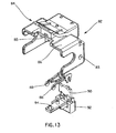
- FIG. 13 is an exploded view of a port ID module of an alternative embodiment
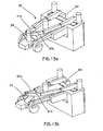
- FIGS. 13a and 13 bare perspective views of a contact assembly of Fig. 13 ;
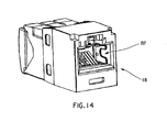
- FIG. 14 is a perspective view of a port ID module inserted into a port
- FIG. 15 is a perspective view of a switch plug of an intelligent interconnect patch cord having a port ID module thereon;
- FIG. 16 is a perspective view of a removal tool positioned for removal of a port ID module
- FIG. 17 is a perspective view of a switch plug showing port ID module plug contacts
- FIG. 18 is a perspective view of the face of an intelligent interconnect patch panel
- FIG. 19 is a perspective view of an intelligent interconnect patch panel port showing its contacts, and a plug positioned for insertion into the port;
- FIG. 20 is a perspective view of an intelligent interconnect patch panel plug according to one embodiment of the present invention.
- FIGS. 21 and 22 are perspective views of a port ID module removal tool according to one embodiment of the current invention.
- FIG. 23 is a perspective view of a port ID module removal tool with a port ID module thereon.
- FIG. 24 is a perspective view of a port ID module removal tool in use.
- FIG. 1 is a block diagram showing system elements in a network switch port identification system 10.
- the port identification system 10 uses intelligent interconnect patch cords 12, intelligent interconnect patch panels 14, and port ID modules 16 within ports 18 of a network switch 20 to enable the management of connections in a communications network.
- Systems and methods according to the present invention may be used to guide a network technician during the movement, addition, or change ("MAC") of an intelligent interconnect patch cord 12.
- Systems and methods according to the present invention may also be used to automatically identify and track current connections within a network.
- the intelligent interconnect patch panel 14 is connected to horizontal cabling as shown by arrow 30, and the horizontal cabling, in turn, is connected to specific network devices such as VOIP phones and computers.
- FIG. 1 shows only one connection, it is to be understood that several connections using intelligent interconnect patch cords 12 are provided between an intelligent interconnect patch panel 14 and a network switch 20.
- an intelligent interconnect patch panel plug 22 of an intelligent interconnect patch cord 12 is inserted into a patch panel port 24, and a switch plug 25 of the patch cord 12 is inserted into a port 18 of the network switch 20.
- the port 18 of the network switch 20 has a port ID module 16 installed therein.
- the port ID module 16 is provided with a unique identification code and circuitry for interfacing with the intelligent interconnect patch cord 12, allowing the unique identification code corresponding to the port 18 to be received by the patch panel microcontroller 26 of the intelligent interconnect patch panel 14. With this information, the intelligent interconnect patch panel 14 can update a network management system 28 with information regarding changes to connections in the network in real time.
- Systems and methods according to the present invention allow for the guidance of cable moves, adds, and changes, through the use of plug LEDs 32 on the intelligent interconnect patch cord 12 and LEDs 34 associated with ports 24 of the intelligent interconnect patch panel 14.
- FIG. 2 is a schematic diagram of an intelligent interconnect patch cord 12 according to one embodiment of the present invention.
- the intelligent interconnect patch cord 12 has four pairs of standard "in-band” conductors 36 for network communications and two "out-of-band” conductors 3 8 that support the functions of the present invention.
- the intelligent interconnect patch panel plug 22 is connected to an intelligent interconnect patch panel 14.
- the four pairs of in-band conductors, 36, are connected via in-band contacts 40 to an intelligent interconnect patch panel 14 in the standard way (e.g., an RJ-45-compatible contact configuration).
- the two out-of-band conductors 38 are connected to an intelligent interconnect patch panel 14 with an integral connector holding intelligent interconnect patch panel plug contacts 42.
- the switch plug 25 is connected to a switch port 18.
- the four pairs of in-band conductors, 36 are connected via in-band contacts 44 to contacts within the switch port 18, similarly to the intelligent interconnect patch panel plug 22.
- the two out-of-band conductors 38 are electrically connected by port ID module plug contacts 46 (which may be plates or spring contacts) on the plug 25 to a port ID module 18 which has been installed (for example, by snapping-in) into the switch port 18.
- the port ID module 18 is an ID chip carrier which remains in a port and identifies the port.
- the intelligent interconnect patch panel 14 is capable of detecting the presence of an intelligent interconnect patch cord 12, and in turn the presence of a port ID module 16, using digital signaling techniques.
- the patch cord microcontroller 48 continuously communicates (e.g., at less-than-200 millisecond intervals) the insertion or removal status of the switch plug and, if inserted, the ID of a port ID module 16 to the intelligent interconnect patch panel microcontroller 26.
- the patch cord microcontroller 48 will also energize LEOs 32 in the switch plug 25 upon receipt of communication signals from the intelligent interconnect patch panel microcontroller 26, which are intermixed with other function signals from the patch cord microcontroller 48 to the intelligent interconnect patch panel microcontroller 26.
- the patch cord microcontroller 48 may include a unique identification number for each intelligent interconnect patch cord 14. This can enable additional information to be acquired by the intelligent interconnect patch panel. For example, if each intelligent interconnect patch cord 12 has a unique ID number, the intelligent interconnect patch panel 12 can inform the NMS 28 when a patch cord has been replaced in the system.
- an intelligent interconnect patch cord 12 is connected to a switch port having a port ID module
- a unique port ID number corresponding to the switch port into which the cord has been installed is immediately transmitted to the intelligent interconnect patch panel 14. If the power to an intelligent interconnect patch panel 14 was off, the port ID number is immediately transmitted to the intelligent interconnect patch panel 14 when the power is restored.
- the network management system 28 is therefore always current for each active switch port.
- an intelligent interconnect patch cord 12 is supplied with a port ID module 16 installed on the switch plug 25.
- the port ID module 16 is automatically installed in the switch port 25.
- the switch plug 25 can be removed; however, under normal circumstances, the port ID module 16 will remain installed in a switch port 18 for the life of a switch.
- a port ID module can be removed with a port ID removal tool; however, in the process, the port ID module is permanently disabled.
- FIG. 3 shows a port ID module 50 according to one embodiment of the present invention.
- the port ID module 50 is adapted for insertion into an RJ-45 port.
- the port ID module 50 has latches 52 that lock the port ID module 50 into an RJ-45 port, but flex during installation, thereby allowing installation to be done using the plug 25 on the intelligent interconnect patch cord 12.
- Crossbeams 54 allow the port ID module 50 to rotate downwardly during the removal process.
- a slider 56 is flush with the front face of the port ID module and, as described below, eliminates the possibility of tampering or removing the port ID module 50 without disabling the module.
- Legs 58 are designed to collapse similarly to springs and take up gaps between the opening of a switch port and the port ID module. This makes it difficult to remove the port ID module 50 without the use of a specially designed removal tool, described below.
- FIG. 4 shows the port ID module 50 positioned for insertion into a port 18.
- FIG. 5 shows a port ID contact assembly 59 of a port ID module.
- the port ID contact assembly 59 has a printed circuit board (PCB) 60, which contains the unique identification number of the port ID module.
- the printed circuit board 60 is connected to port ID module contacts 62, which are adapted to contact port ID module plug contacts 46 of the switch plug 25 (shown in FIGS. 1 and 2 ) of an intelligent interconnect patch cord 12.
- a slider 56 has a shorting plate 64 mounted thereon.
- FIG. 5 shows the slider 56 in a "non-shorting" position, which allows normal operation of the port ID module.
- protrusions 66 of the port ID module contacts 62 are shorted together, disabling normal operation of the port ID module.
- the slider 56 may be pushed backwardly by a removal tool or by tampering with the port ID module 50. Bent portions 65 of the port ID module contacts 62 make contact with the port ID module plug contacts 46 of the switch plug 25 when the switch plug is inserted into a port 18 with the port ID module 50 installed.
- FIG. 7 is a cross-sectional view through a port ID module contact 62, with the slider in a forward position, allowing normal operation of the port ID module.
- the slider 56 exerts pressure on the protrusion 66 of the port ID module contact 62, assuring continuity between traces on the PCB 60 and the contact 62.
- FIG. 8 is a cross-sectional view through the slider 56 when the slider is in its forward, non-shorting position.
- a post 68 of the port ID module extends through a hole 70 in the slider 56.
- FIG. 9 shows the slider 56 pushed to its rear, shorting position by an extension 72 of a removal tool 74. The post 68 has been severed, and a portion of the post 68 remains in the hole 70.
- a latch 76 of the removal tool has engaged the port ID module, allowing the port ID module to be rotated as shown in FIG. 10 and removed from the port.
- FIG. 11 shows the removal tool 74 with the port ID module 50 thereon.
- a latch lever 78 on the removal tool can be depressed to allow removal of the port ID module 50 from the tool.
- FIG. 12 shows a switch plug 80 according to one embodiment of an intelligent interconnect patch cord.
- the switch plug 80 has another embodiment of a port ID module 82 provided thereon.
- the switch plug 80 is ready for insertion into a switch port. Following this insertion, the port ID module 82 will remain installed in the switch port, retained by latches 84.
- FIG. 13 is an exploded perspective view of another embodiment of the port ID module 82, showing a port ID module housing 86, port ID module contacts 88, a PCB assembly 90, and a PCB housing 92.
- the PCB assembly 90 contains the ID number of the port ID module 82, and is electrically connected to the port ID module contacts 88.
- a post 94 of the PCB housing 92 keeps the port ID module contacts 88 separated. After removal or tampering of the port ID module 82, however, the post 94 is broken, allowing the port ID module contacts 88 to short out and thereby disabling the port ID module 82.
- FIG. 13a shows an assembled contact assembly 95 as illustrated in FIG. 13 in an active (non-disabled) state, with the post 94 separating the contact portions 97a and 97b.
- FIG. 13b shows the contact assembly 95 with the post 94 broken so that the contact portions 97a and 97b are in electrical contact due to the spring force between the contact portions.
- FIG. 14 shows the port ID module 82 installed within a port 18.
- FIG. 15 is a perspective view of the switch plug 80, in which a PCB 96 supporting the patch cord microcontroller 48 is visible.
- First and second contacts 98a and 98b allow the PCB 96 to electrically communicate with the intelligent interconnect patch panel via the out-of-band conductors 38 of the intelligent interconnect patch cord.
- FIG. 16 is a perspective view of a removal tool 100 positioned to remove a port ID module 82 from a port 18.
- FIG. 17 is a perspective view of the switch plug 80 without a port ID module attached. Port ID module plug contacts 102, which make electrical contact with the port ID module contacts 88, are shown.
- FIG. 18 is a perspective view of the face of an intelligent interconnect patch panel 14, showing an intelligent interconnect patch panel port 24 and its associated LED 34.
- Intelligent interconnect patch panel contacts 35 are positioned above the port 24 and are adapted for connection with the intelligent interconnect patch panel plug contacts 42 (shown in FIG. 2 ). This allows communication between the intelligent interconnect patch panel 14 and port ID modules according to the present invention.
- the LED 34 and the LEDs 32 of the intelligent interconnect patch cord may be used by the system to guide a technician to the location of a required action and indicate correct or incorrect cable connections to a technician. This may be done by changing the on/off state of the LEDs, using different flashing rates, and/or using different colors for the LEDs.
- FIG. 19 is a perspective view of an intelligent interconnect patch panel port 24.
- Intelligent interconnect patch panel port contacts 104a and 104b are located above the port 24.
- the intelligent interconnect patch panel port contacts 104a and 104b enable electrical connection between the intelligent interconnect patch panel 14 and the out-of-band conductors 36 of an intelligent interconnect patch cord.
- the contacts 104a and 104b are vertically offset, and they are adapted to contact intelligent interconnect patch panel plug contacts 42a and 42b of the intelligent interconnect patch panel plug 22.
- the intelligent interconnect patch panel port contacts 104a and 104b are provided with flexible members 106, which are electrically connected to a PCB 108 of the intelligent interconnect patch panel 14, and the contacts are held in place by a contact housing 110.
- the housing 110 and the flexible members 106 hold the contacts 104a and 104b in place, allowing some freedom of movement for the contacts 104a and 104b, while assuring adequate contact force on the plug contacts 42a and 42b.
- FIG. 20 is a perspective view of a patch panel plug 22, showing the intelligent interconnect patch panel plug contacts 42a and 42b.
- the contacts 42a and 42b are separated from one another by an insulative layer 112, and are respectively connected to first and second out-of-band conductors 38 (not shown in FIG. 20 ).
- FIGS. 21 and 22 show an alternative embodiment of a port ID module removal tool 120, for use with the port ID module 82 shown in FIG. 13 .
- Latch members 122 engage holes 83 of the port ID module 82, such that the port ID module 82 becomes latched onto the removal tool 120.
- a protrusion 124 is inserted into a hole 85 in the module 84 to break the post 94 and disable the module 84.
- Sliders 126 disengage latches 84 to allow removal of the module 84 from a port.
- a handle128 is provided to allow easier use by a technician.
- FIG. 23 shows a port ID module 84 on the end of a port ID removal tool 120
- FIG. 24 shows the port ID removal tool 120 inserted into a port 18 during the removal process.
- port ID modules have been shown inserted into switch ports, it is to be understood that port ID modules may be inserted into other types of communications ports.
Landscapes
- Engineering & Computer Science (AREA)
- Computer Networks & Wireless Communication (AREA)
- Details Of Connecting Devices For Male And Female Coupling (AREA)
- Small-Scale Networks (AREA)
Abstract
Description
- The present application incorporates by reference in their entireties
U.S. Patent Application Serial No. 11/265,316 U.S. Patent Application Serial No. 11/560,112 - Patch panels are used in communications networks as intermediate elements between horizontal cabling (to which endpoint devices such as computers and telephones are connected) and network switches. When physical connections between endpoint devices and network switches are moved, added, or changed, patch panels are typically the points at which technicians complete the required moves, additions, or changes. It is important to keep track of changes that are made to patch cord connections within the patch field. Proper documentation of changes in the patch field assures that the routing of patch cords is always known and further assures that any future changes are completed correctly.
- In interconnect network configurations, one patch panel is placed between the horizontal cabling and the network switch. In an interconnect configuration, the documentation of patch cord connections between the patch panel and the switch will provide the necessary documentation and monitoring of connections between the switch and the horizontal cabling. It is desirable to have a patch cord management system that enables complete documentation and monitoring of patch cord connections and that guides network installers as they make moves, adds, or changes to the patch cord connections. It is also desirable for a patch cord management system to have a minimal impact on existing networks.
- State-of-the-art patch cord documentation systems for interconnect applications require the addition of contact plates on printed circuit boards which are fastened to the front of switches and which have cables that connect the printed circuit boards to monitoring systems. The monitoring systems scan 9th wire connections between the switch contact plates and contact plates on the front of an associated patch panel. This is typically a retrofit installation which requires a variety of parts due to the variety of switch configurations.
- There is a need for an improved port identification system which works with a patch panel to identify ports, such as switch ports, in a communications network. Such a system should be easy to install and compact, while providing port identification functionality without delays.
- According to one embodiment of the present invention, port ID modules are installed in the ports of a network switch. An intelligent interconnect patch panel, which is connected to the network switch, is adapted for use with intelligent interconnect patch cords and the port ID modules to enable the management of connections between the intelligent interconnect patch panel and the network switch.
- Port ID modules are provided with unique identification numbers within port ID module circuitry.
- Port ID modules according to the present invention may be removed and disabled with the use of a removal tool.
-
FIG. 1 is a schematic block diagram showing components and communication connections of a switch port identification system; -
FIG. 2 is a schematic block diagram of an intelligent interconnect patch cord according to one embodiment of the present invention; -
FIGS. 3 and 4 are perspective diagrams of a port ID module according to one embodiment of the present invention; -
FIGS. 5 and 6 are perspective diagrams of a port ID contact assembly according to one embodiment of the current invention; -
FIGS. 7-10 are sectional drawings showing the operation of a port ID module; -
FIG. 11 is a perspective view of a port ID module and a removal tool; -
FIG. 12 is a perspective view of a switch plug with a port ID module thereon; -
FIG. 13 is an exploded view of a port ID module of an alternative embodiment; -
FIGS. 13a and13 bare perspective views of a contact assembly ofFig. 13 ; -
FIG. 14 is a perspective view of a port ID module inserted into a port; -
FIG. 15 is a perspective view of a switch plug of an intelligent interconnect patch cord having a port ID module thereon; -
FIG. 16 is a perspective view of a removal tool positioned for removal of a port ID module; -
FIG. 17 is a perspective view of a switch plug showing port ID module plug contacts; -
FIG. 18 is a perspective view of the face of an intelligent interconnect patch panel; -
FIG. 19 is a perspective view of an intelligent interconnect patch panel port showing its contacts, and a plug positioned for insertion into the port; and -
FIG. 20 is a perspective view of an intelligent interconnect patch panel plug according to one embodiment of the present invention; -
FIGS. 21 and 22 are perspective views of a port ID module removal tool according to one embodiment of the current invention; -
FIG. 23 is a perspective view of a port ID module removal tool with a port ID module thereon; and -
FIG. 24 is a perspective view of a port ID module removal tool in use. -
FIG. 1 is a block diagram showing system elements in a network switchport identification system 10. Theport identification system 10 uses intelligentinterconnect patch cords 12, intelligentinterconnect patch panels 14, andport ID modules 16 withinports 18 of anetwork switch 20 to enable the management of connections in a communications network. Systems and methods according to the present invention may be used to guide a network technician during the movement, addition, or change ("MAC") of an intelligentinterconnect patch cord 12. Systems and methods according to the present invention may also be used to automatically identify and track current connections within a network. - The intelligent
interconnect patch panel 14 is connected to horizontal cabling as shown byarrow 30, and the horizontal cabling, in turn, is connected to specific network devices such as VOIP phones and computers. AlthoughFIG. 1 shows only one connection, it is to be understood that several connections using intelligentinterconnect patch cords 12 are provided between an intelligentinterconnect patch panel 14 and anetwork switch 20. - In the
port identification system 10, an intelligent interconnectpatch panel plug 22 of an intelligentinterconnect patch cord 12 is inserted into apatch panel port 24, and aswitch plug 25 of thepatch cord 12 is inserted into aport 18 of thenetwork switch 20. Theport 18 of thenetwork switch 20 has aport ID module 16 installed therein. Theport ID module 16 is provided with a unique identification code and circuitry for interfacing with the intelligentinterconnect patch cord 12, allowing the unique identification code corresponding to theport 18 to be received by thepatch panel microcontroller 26 of the intelligentinterconnect patch panel 14. With this information, the intelligentinterconnect patch panel 14 can update anetwork management system 28 with information regarding changes to connections in the network in real time. - Systems and methods according to the present invention allow for the guidance of cable moves, adds, and changes, through the use of
plug LEDs 32 on the intelligentinterconnect patch cord 12 andLEDs 34 associated withports 24 of the intelligentinterconnect patch panel 14. -
FIG. 2 is a schematic diagram of an intelligentinterconnect patch cord 12 according to one embodiment of the present invention. The intelligentinterconnect patch cord 12 has four pairs of standard "in-band"conductors 36 for network communications and two "out-of-band" conductors 3 8 that support the functions of the present invention. - The intelligent interconnect
patch panel plug 22 is connected to an intelligentinterconnect patch panel 14. The four pairs of in-band conductors, 36, are connected via in-band contacts 40 to an intelligentinterconnect patch panel 14 in the standard way (e.g., an RJ-45-compatible contact configuration). The two out-of-band conductors 38 are connected to an intelligentinterconnect patch panel 14 with an integral connector holding intelligent interconnect patchpanel plug contacts 42. - Referring now to
FIGS. 1 and2 , theswitch plug 25 is connected to aswitch port 18. The four pairs of in-band conductors, 36, are connected via in-band contacts 44 to contacts within theswitch port 18, similarly to the intelligent interconnectpatch panel plug 22. When theplug 25 is installed, the two out-of-band conductors 38 are electrically connected by port ID module plug contacts 46 (which may be plates or spring contacts) on theplug 25 to aport ID module 18 which has been installed (for example, by snapping-in) into theswitch port 18. Theport ID module 18 is an ID chip carrier which remains in a port and identifies the port. - Referring to
FIGS. 1 and2 , in one embodiment of the present invention, the intelligentinterconnect patch panel 14 is capable of detecting the presence of an intelligentinterconnect patch cord 12, and in turn the presence of aport ID module 16, using digital signaling techniques. - When an intelligent
interconnect patch cord 12 is plugged into apatch panel port 24 of the intelligentinterconnect patch panel 14, the out-of-band conductors 38 (shown inFIG. 2 ) are connected throughcontacts 42 of the intelligent interconnectpatch panel plug 22 to apatch panel microcontroller 26 in the intelligentinterconnect patch panel 14. This completes a two-conductor connection to apatch cord microcontroller 48 in theswitch plug 25 of the intelligent interconnect patch cord. This enables what is known in the art as a "one wire" serial communication in either direction between the microcontrollers, and it also provides DC voltage to thepatch cord microcontroller 48. - When the
switch plug 25 is connected to aswitch port 18 that contains aport ID module 16, two conductors of the switch plug are connected through port ID module contacts to an ID chip in theport ID module 16. This enables one-wire serial communication between thepatch cord microcontroller 48 and the ID chip in theport ID module 16. During normal operation, this serial digital communication occurs constantly (repeating, for example, at less-than-200 millisecond intervals) and communicates to thepatch cord microcontroller 48 the ID of theport 18 to which the switch plug is connected. If a port ID module is disabled, there is a short circuit across the ID chip and hence across these two conductors, which is detected by thepatch cord microcontroller 48. If a switch plug is disconnected or if there is no port ID module in a switch port, there is an open circuit across the two switch plug conductors, and this open circuit is detected by thepatch cord microcontroller 48. - The
patch cord microcontroller 48 continuously communicates (e.g., at less-than-200 millisecond intervals) the insertion or removal status of the switch plug and, if inserted, the ID of aport ID module 16 to the intelligent interconnectpatch panel microcontroller 26. Thepatch cord microcontroller 48 will also energizeLEOs 32 in theswitch plug 25 upon receipt of communication signals from the intelligent interconnectpatch panel microcontroller 26, which are intermixed with other function signals from thepatch cord microcontroller 48 to the intelligent interconnectpatch panel microcontroller 26. - The
patch cord microcontroller 48 may include a unique identification number for each intelligentinterconnect patch cord 14. This can enable additional information to be acquired by the intelligent interconnect patch panel. For example, if each intelligentinterconnect patch cord 12 has a unique ID number, the intelligentinterconnect patch panel 12 can inform theNMS 28 when a patch cord has been replaced in the system. - Using this system, if an intelligent
interconnect patch cord 12 is connected to a switch port having a port ID module, a unique port ID number corresponding to the switch port into which the cord has been installed is immediately transmitted to the intelligentinterconnect patch panel 14. If the power to an intelligentinterconnect patch panel 14 was off, the port ID number is immediately transmitted to the intelligentinterconnect patch panel 14 when the power is restored. Thenetwork management system 28 is therefore always current for each active switch port. - According to one embodiment, an intelligent
interconnect patch cord 12 is supplied with aport ID module 16 installed on theswitch plug 25. When theswitch plug 25 is installed in a switch port, theport ID module 16 is automatically installed in theswitch port 25. The switch plug 25 can be removed; however, under normal circumstances, theport ID module 16 will remain installed in aswitch port 18 for the life of a switch. As shown in figures below, a port ID module can be removed with a port ID removal tool; however, in the process, the port ID module is permanently disabled. -
FIG. 3 shows aport ID module 50 according to one embodiment of the present invention. Theport ID module 50 is adapted for insertion into an RJ-45 port. Theport ID module 50 haslatches 52 that lock theport ID module 50 into an RJ-45 port, but flex during installation, thereby allowing installation to be done using theplug 25 on the intelligentinterconnect patch cord 12.Crossbeams 54 allow theport ID module 50 to rotate downwardly during the removal process. Aslider 56 is flush with the front face of the port ID module and, as described below, eliminates the possibility of tampering or removing theport ID module 50 without disabling the module.Legs 58 are designed to collapse similarly to springs and take up gaps between the opening of a switch port and the port ID module. This makes it difficult to remove theport ID module 50 without the use of a specially designed removal tool, described below. -
FIG. 4 shows theport ID module 50 positioned for insertion into aport 18. -
FIG. 5 shows a portID contact assembly 59 of a port ID module. The portID contact assembly 59 has a printed circuit board (PCB) 60, which contains the unique identification number of the port ID module. The printedcircuit board 60 is connected to portID module contacts 62, which are adapted to contact port IDmodule plug contacts 46 of the switch plug 25 (shown inFIGS. 1 and2 ) of an intelligentinterconnect patch cord 12. Aslider 56 has a shortingplate 64 mounted thereon.FIG. 5 shows theslider 56 in a "non-shorting" position, which allows normal operation of the port ID module. - When the
slider 56 is pushed backwardly into the position shown inFIG. 6 ,protrusions 66 of the portID module contacts 62 are shorted together, disabling normal operation of the port ID module. Theslider 56 may be pushed backwardly by a removal tool or by tampering with theport ID module 50.Bent portions 65 of the portID module contacts 62 make contact with the port IDmodule plug contacts 46 of theswitch plug 25 when the switch plug is inserted into aport 18 with theport ID module 50 installed. -
FIG. 7 is a cross-sectional view through a portID module contact 62, with the slider in a forward position, allowing normal operation of the port ID module. Theslider 56 exerts pressure on theprotrusion 66 of the portID module contact 62, assuring continuity between traces on thePCB 60 and thecontact 62. -
FIG. 8 is a cross-sectional view through theslider 56 when the slider is in its forward, non-shorting position. Apost 68 of the port ID module extends through ahole 70 in theslider 56.FIG. 9 shows theslider 56 pushed to its rear, shorting position by anextension 72 of aremoval tool 74. Thepost 68 has been severed, and a portion of thepost 68 remains in thehole 70. Alatch 76 of the removal tool has engaged the port ID module, allowing the port ID module to be rotated as shown inFIG. 10 and removed from the port.FIG. 11 shows theremoval tool 74 with theport ID module 50 thereon. Alatch lever 78 on the removal tool can be depressed to allow removal of theport ID module 50 from the tool. -
FIG. 12 shows aswitch plug 80 according to one embodiment of an intelligent interconnect patch cord. The switch plug 80 has another embodiment of aport ID module 82 provided thereon. In the configuration shown inFIG. 12 , theswitch plug 80 is ready for insertion into a switch port. Following this insertion, theport ID module 82 will remain installed in the switch port, retained bylatches 84. -
FIG. 13 is an exploded perspective view of another embodiment of theport ID module 82, showing a portID module housing 86, portID module contacts 88, aPCB assembly 90, and aPCB housing 92. ThePCB assembly 90 contains the ID number of theport ID module 82, and is electrically connected to the portID module contacts 88. In normal operation, apost 94 of thePCB housing 92 keeps the portID module contacts 88 separated. After removal or tampering of theport ID module 82, however, thepost 94 is broken, allowing the portID module contacts 88 to short out and thereby disabling theport ID module 82. -
FIG. 13a shows an assembledcontact assembly 95 as illustrated inFIG. 13 in an active (non-disabled) state, with thepost 94 separating thecontact portions FIG. 13b shows thecontact assembly 95 with thepost 94 broken so that thecontact portions -
FIG. 14 shows theport ID module 82 installed within aport 18. -
FIG. 15 is a perspective view of theswitch plug 80, in which aPCB 96 supporting thepatch cord microcontroller 48 is visible. First andsecond contacts PCB 96 to electrically communicate with the intelligent interconnect patch panel via the out-of-band conductors 38 of the intelligent interconnect patch cord. -
FIG. 16 is a perspective view of aremoval tool 100 positioned to remove aport ID module 82 from aport 18. -
FIG. 17 is a perspective view of theswitch plug 80 without a port ID module attached. Port IDmodule plug contacts 102, which make electrical contact with the portID module contacts 88, are shown. -
FIG. 18 is a perspective view of the face of an intelligentinterconnect patch panel 14, showing an intelligent interconnectpatch panel port 24 and its associatedLED 34. Intelligent interconnectpatch panel contacts 35 are positioned above theport 24 and are adapted for connection with the intelligent interconnect patch panel plug contacts 42 (shown inFIG. 2 ). This allows communication between the intelligentinterconnect patch panel 14 and port ID modules according to the present invention. TheLED 34 and theLEDs 32 of the intelligent interconnect patch cord may be used by the system to guide a technician to the location of a required action and indicate correct or incorrect cable connections to a technician. This may be done by changing the on/off state of the LEDs, using different flashing rates, and/or using different colors for the LEDs. -
FIG. 19 is a perspective view of an intelligent interconnectpatch panel port 24. Intelligent interconnect patchpanel port contacts port 24. The intelligent interconnect patchpanel port contacts interconnect patch panel 14 and the out-of-band conductors 36 of an intelligent interconnect patch cord. Thecontacts panel plug contacts patch panel plug 22. The intelligent interconnect patchpanel port contacts flexible members 106, which are electrically connected to aPCB 108 of the intelligentinterconnect patch panel 14, and the contacts are held in place by acontact housing 110. Thehousing 110 and theflexible members 106 hold thecontacts contacts plug contacts -
FIG. 20 is a perspective view of apatch panel plug 22, showing the intelligent interconnect patchpanel plug contacts contacts insulative layer 112, and are respectively connected to first and second out-of-band conductors 38 (not shown inFIG. 20 ). -
FIGS. 21 and 22 show an alternative embodiment of a port IDmodule removal tool 120, for use with theport ID module 82 shown inFIG. 13 .Latch members 122 engageholes 83 of theport ID module 82, such that theport ID module 82 becomes latched onto theremoval tool 120. Aprotrusion 124 is inserted into ahole 85 in themodule 84 to break thepost 94 and disable themodule 84.Sliders 126 disengage latches 84 to allow removal of themodule 84 from a port. A handle128 is provided to allow easier use by a technician.FIG. 23 shows aport ID module 84 on the end of a portID removal tool 120, andFIG. 24 shows the portID removal tool 120 inserted into aport 18 during the removal process. - As will be understood from the above, the following are among the benefits of the present invention:
- Easy installation;
- Real-time protection against errors or intrusion, even following a power interruption;
- The systems are compact;
- The systems provide move, add, and change (MAC) guidance to technicians;
- No additional cables dedicated to management functions are required;
- The system is self-documenting;
- There are no scanning delays in the system;
- There is no effect on in-band signals or Power Over Ethernet (POE);
- Disconnection of either plug of a patch cord is immediately detected; and
- Systems may be used in high-density switch port environments.
- While particular embodiments and applications of the present invention have been illustrated and described, it is to be understood that the invention is not limited to the precise construction and compositions disclosed herein and that various modifications, changes, and variations may be apparent from the foregoing descriptions without departing from the spirit and scope of the invention. For example, while port ID modules have been shown inserted into switch ports, it is to be understood that port ID modules may be inserted into other types of communications ports.
Claims (10)
- A system for identifying ports in a communication system, comprising:a network switch having a plurality of network switch ports;an intelligent interconnect patch panel having a plurality of patch panel ports;at least one intelligent interconnect patch cord connected between one of said network switch ports and one of said patch panel ports; anda plurality of port ID modules, each of said port ID modules being inserted within one of said network switch ports and having a unique port ID code associated therewith.
- The system of claim 1 wherein said intelligent interconnect patch cord comprises at least two out-of-band conductors.
- The system of claim 2 wherein said intelligent interconnect patch cord comprises a switch plug and a patch panel plug.
- The system of claim 3 wherein said out-of-band conductors are in electrical communication with port ID module plug contacts of said switch plug of said intelligent interconnect patch cord.
- The system of claim 4 wherein each of said port ID modules comprises port ID module contacts that are adapted to be in electrical contact with said port ID module plug contacts of said switch plug of said intelligent interconnect patch cord.
- The system of claim 1 wherein said intelligent interconnect patch panel comprises a patch panel microcontroller adapted to receive said unique port ID code of a port ID module when said intelligent interconnect patch cord is plugged into a switch port having said port ID module installed therein.
- The system of claim 1 wherein each of said port ID modules comprises a printed circuit board on which said unique port ID code is stored.
- The system of claim 7 wherein each of said port ID modules comprises two port ID module contacts electrically connected to said printed circuit board.
- The system of claim 8 wherein said port ID module contacts may be shorted together in a disabling operation.
- The system of claim 9 wherein said disabling operation results when one of said port ID modules is tampered with or removed from its corresponding switch port.
Applications Claiming Priority (2)
| Application Number | Priority Date | Filing Date | Title |
|---|---|---|---|
| US98135307P | 2007-10-19 | 2007-10-19 | |
| EP08840557A EP2206355B1 (en) | 2007-10-19 | 2008-10-17 | Communication port identification system |
Related Parent Applications (1)
| Application Number | Title | Priority Date | Filing Date |
|---|---|---|---|
| EP08840557.6 Division | 2008-10-17 |
Publications (2)
| Publication Number | Publication Date |
|---|---|
| EP2288174A2 true EP2288174A2 (en) | 2011-02-23 |
| EP2288174A3 EP2288174A3 (en) | 2011-04-27 |
Family
ID=40568082
Family Applications (2)
| Application Number | Title | Priority Date | Filing Date |
|---|---|---|---|
| EP10193789A Withdrawn EP2288174A3 (en) | 2007-10-19 | 2008-10-17 | Communication port identification system |
| EP08840557A Not-in-force EP2206355B1 (en) | 2007-10-19 | 2008-10-17 | Communication port identification system |
Family Applications After (1)
| Application Number | Title | Priority Date | Filing Date |
|---|---|---|---|
| EP08840557A Not-in-force EP2206355B1 (en) | 2007-10-19 | 2008-10-17 | Communication port identification system |
Country Status (4)
| Country | Link |
|---|---|
| US (1) | US8477031B2 (en) |
| EP (2) | EP2288174A3 (en) |
| AT (1) | ATE509473T1 (en) |
| WO (1) | WO2009052381A2 (en) |
Cited By (1)
| Publication number | Priority date | Publication date | Assignee | Title |
|---|---|---|---|---|
| CN103491459A (en) * | 2013-09-30 | 2014-01-01 | 北京星网锐捷网络技术有限公司 | Electronic distributing frame system |
Families Citing this family (20)
| Publication number | Priority date | Publication date | Assignee | Title |
|---|---|---|---|---|
| CA2756267A1 (en) | 2009-02-13 | 2010-08-19 | Adc Telecommunications, Inc. | Network management systems for use with physical layer information |
| KR101709348B1 (en) * | 2009-05-08 | 2017-02-23 | 삼성전자주식회사 | Apparatus and method for generating visible signal according to data transmitting rate in visible light communication system |
| US9948392B2 (en) | 2009-05-08 | 2018-04-17 | Samsung Electronics Co., Ltd | Apparatus and method for generating visible signal according to amount of data transmission in visible light communication system |
| US8643476B2 (en) | 2009-06-29 | 2014-02-04 | Commscope, Inc. Of North Carolina | Dynamic labeling of patch panel ports |
| US9123217B2 (en) | 2009-06-29 | 2015-09-01 | Commscope, Inc. Of North Carolina | Methods of automatically recording patching changes at passive patch panels and network equipment |
| US9538262B2 (en) * | 2009-08-21 | 2017-01-03 | Commscope, Inc. Of North Carolina | Systems, equipment and methods for automatically tracking cable connections and for identifying work area devices and related methods of operating communications networks |
| US8994547B2 (en) * | 2009-08-21 | 2015-03-31 | Commscope, Inc. Of North Carolina | Systems for automatically tracking patching connections to network devices using a separate control channel and related patching equipment and methods |
| US8992260B2 (en) | 2009-10-16 | 2015-03-31 | Adc Telecommunications, Inc. | Managed connectivity in electrical systems and methods thereof |
| US8690593B2 (en) | 2010-02-12 | 2014-04-08 | Adc Telecommunications, Inc. | Managed fiber connectivity systems |
| CN103069506B (en) * | 2010-08-23 | 2017-03-15 | 北卡罗来纳康姆斯科普公司 | Conductive elements in cable jackets and barriers |
| WO2012098538A1 (en) * | 2010-12-28 | 2012-07-26 | Rit Technologies Ltd. | Two-part modular connector and smart managed interconnect link using the two-part modular connector |
| US8947106B2 (en) | 2011-01-21 | 2015-02-03 | Commscope, Inc. Of North Carolina | Plug insertion detection circuits that sense a change in capacitance and related methods and communications connectors |
| CN103217744B (en) * | 2012-01-19 | 2016-03-30 | 华为技术有限公司 | Optical device, for managing the system and method for optical device |
| US11113642B2 (en) | 2012-09-27 | 2021-09-07 | Commscope Connectivity Uk Limited | Mobile application for assisting a technician in carrying out an electronic work order |
| EP2954695A4 (en) * | 2013-02-05 | 2016-09-21 | Adc Telecommunications Inc | SYSTEMS AND METHODS FOR ASSOCIATING POSITION DATA WITH A COMMUNICATION SUBSEMBLY HOSTED IN A COMMUNICATION SET |
| US9454501B2 (en) * | 2013-07-30 | 2016-09-27 | Leviton Manufacturing Co., Inc. | Intelligent patch panel port monitoring system |
| EP3042355A4 (en) | 2013-09-04 | 2017-04-19 | CommScope Technologies LLC | Physical layer system with support for multiple active work orders and/or multiple active technicians |
| US20160062939A1 (en) * | 2014-08-31 | 2016-03-03 | Airborn, Inc. | Connector with in-circuit programming |
| US10210068B2 (en) | 2015-04-13 | 2019-02-19 | Leviton Manufacturing Co., Inc. | Device topology definition system |
| US10841813B2 (en) | 2015-04-23 | 2020-11-17 | Telefonaktiebolaget Lm Ericsson (Publ) | Device to guide equipment cable installation between radio ports of a base station and multiple antennas |
Family Cites Families (153)
| Publication number | Priority date | Publication date | Assignee | Title |
|---|---|---|---|---|
| US3052842A (en) * | 1959-10-15 | 1962-09-04 | Lockheed Aircraft Corp | Patchcord connection aid and checking system |
| US3573792A (en) * | 1968-11-12 | 1971-04-06 | Us Navy | Universal display panel |
| US3573789A (en) * | 1968-12-13 | 1971-04-06 | Ibm | Method and apparatus for increasing image resolution |
| US3914561A (en) * | 1971-12-08 | 1975-10-21 | American Telephone & Telegraph | Apparatus and method for tracing jumpers in a main distributing frame |
| US4018997A (en) * | 1974-05-10 | 1977-04-19 | Amp Incorporated | Pluggable key set telephone cross connect device |
| CA1012270A (en) * | 1974-06-19 | 1977-06-14 | Arie Verhagen | Modular interchange termination system |
| US4072827A (en) * | 1976-09-15 | 1978-02-07 | Oman Robert C | Telephone patching apparatus |
| US4096359A (en) * | 1976-10-12 | 1978-06-20 | International Standard Electric Corporation | Key telephone system interconnection apparatus |
| US4196316A (en) * | 1977-09-13 | 1980-04-01 | Bell Telephone Laboratories, Incorporated | Program controlled communication system having individually rearrangeable line selection |
| US4169220A (en) * | 1978-10-02 | 1979-09-25 | Fields Gary C | Telephone instrument connection block with remotely actuated line test |
| JPS5895927A (en) * | 1981-12-02 | 1983-06-07 | 三菱電機株式会社 | Protecting relay system |
| US4673246A (en) * | 1984-08-24 | 1987-06-16 | Pacific Bell | Patch unit for fiber optic distribution network |
| KR870011719A (en) * | 1986-05-28 | 1987-12-26 | 쓰지 하루오 | Connection device |
| US4773867A (en) * | 1986-07-02 | 1988-09-27 | Amp Incorporated | Premise distribution cross connect apparatus |
| JPS63139499A (en) * | 1986-12-02 | 1988-06-11 | Toshiba Corp | Port connection system for electronic exchange |
| US4890102A (en) * | 1987-05-26 | 1989-12-26 | Cabletron, Inc. | Visual display for communication network monitoring and troubleshooting |
| AT387873B (en) | 1987-06-25 | 1989-03-28 | Sprecher Energie Oesterreich | DEVICE FOR CONTROLLING AND MONITORING AN ELECTRICAL POWER DISTRIBUTION SYSTEM |
| US4901004A (en) * | 1988-12-09 | 1990-02-13 | King Fred N | Apparatus and method for mapping the connectivity of communications systems with multiple communications paths |
| JPH0221683A (en) * | 1988-07-08 | 1990-01-24 | Mitsubishi Electric Corp | Semiconductor laser device |
| US5111408A (en) * | 1988-10-19 | 1992-05-05 | Hewlett-Packard Company | Digital image documentation system |
| US4937529A (en) * | 1989-01-30 | 1990-06-26 | Toole Iii Charles S O | Electrical conductor identifying assembly |
| US5037167A (en) * | 1989-05-01 | 1991-08-06 | Alcatel Na, Inc. | Electrical and fiber optic cable control and management |
| US5081627A (en) * | 1989-07-05 | 1992-01-14 | Casat Technologies, Inc. | Status and activity monitor for contention type local area networks |
| US5107532A (en) * | 1989-09-22 | 1992-04-21 | Cable Management International, Inc. | Automated documentation system for a communications network |
| GB2236398A (en) | 1989-09-29 | 1991-04-03 | James Alexander Carter | Self documenting patch panel |
| US5226120A (en) * | 1990-05-21 | 1993-07-06 | Synoptics Communications, Inc. | Apparatus and method of monitoring the status of a local area network |
| US5170327A (en) * | 1990-11-05 | 1992-12-08 | Adc Telecommunications, Inc. | Distal distribution frame module |
| IL97227A0 (en) * | 1991-02-13 | 1992-05-25 | Bynet System Applic Ltd | Patching panel |
| US5145380A (en) * | 1991-06-17 | 1992-09-08 | Homaco, Inc. | Patch panel |
| FR2680067B1 (en) | 1991-08-01 | 1995-05-12 | Cit Alcatel | METHOD FOR CONTROLLING A LINE DISTRIBUTOR; AUXILIARY CABLE, CONNECTOR AND DISTRIBUTOR FOR THE IMPLEMENTATION OF THIS PROCESS. |
| US5270658A (en) * | 1991-08-19 | 1993-12-14 | Epstein Barry M | Means and method for testing and monitoring a circuit breaker panel assembly |
| US5204929A (en) * | 1991-09-04 | 1993-04-20 | Reliance Comm/Tec Corporation | Fiber patch panel |
| US5487666A (en) * | 1991-12-31 | 1996-01-30 | Digiovanni; Thomas H. | Schematic patch panel |
| JP2940843B2 (en) * | 1992-01-23 | 1999-08-25 | 三菱電機株式会社 | Overcurrent protection method and device, and overcurrent detection device |
| US5233501A (en) * | 1992-02-27 | 1993-08-03 | Telect, Inc. | Digital telecommunication network cross-connect module having a printed circuit board connected to jack switches |
| EP0575100B1 (en) | 1992-06-10 | 1998-04-29 | Rit Technologies Ltd. | Patching panel scanner |
| US5483467A (en) * | 1992-06-10 | 1996-01-09 | Rit Technologies, Ltd. | Patching panel scanner |
| US5222164A (en) * | 1992-08-27 | 1993-06-22 | International Business Machines Corporation | Electrically isolated optical connector identification system |
| CA2081608C (en) * | 1992-10-28 | 1998-05-05 | Joseph Octave Regis Morin | Distribution frame and optical connector holder combination |
| US5305405A (en) * | 1993-02-25 | 1994-04-19 | Adc Telecommunications, Inc. | Patch cord |
| US5541586A (en) * | 1993-05-03 | 1996-07-30 | The Whitaker Corporation | Visual outlet identification in a cable management system |
| US5394503A (en) | 1993-10-08 | 1995-02-28 | Data Switch Corporation | Optical fiber connection monitoring apparatus, patch panel control system and method of using same |
| US5353367A (en) * | 1993-11-29 | 1994-10-04 | Northern Telecom Limited | Distribution frame and optical connector holder combination |
| EP0658032B1 (en) * | 1993-12-06 | 2001-09-26 | Agilent Technologies Inc. a Delaware Corporation | Location identification in a communications signalling network |
| US5459478A (en) * | 1993-12-27 | 1995-10-17 | Illinois Tool Works, Inc. | Aircraft cockpit switch circuitry |
| US5463706A (en) * | 1994-02-16 | 1995-10-31 | Thomas & Betts Corporation | Light traceable transmission conduit assembly |
| US5432847A (en) * | 1994-03-29 | 1995-07-11 | Telect, Inc. | Low frequency telecommunication digital network interface patch panel |
| FR2718546B1 (en) * | 1994-04-08 | 1996-05-31 | Luc Lebeau | Computer link device between devices with heterogeneous communication systems, key relating to such a device. |
| US5684796A (en) * | 1994-05-03 | 1997-11-04 | Bay Networks Group, Inc. | Method and apparatus for determining and maintaining agent topology information in a multi-segment network |
| US5550755A (en) * | 1994-07-14 | 1996-08-27 | Martin; B. Morgan | Apparatus and method for patch recording and recall |
| US5666453A (en) * | 1994-07-15 | 1997-09-09 | Roy Witte | Fiber optic jumper cables and tracing method using same |
| US5727055A (en) * | 1995-05-17 | 1998-03-10 | Ies Technologies, Inc. | Information communication systems |
| IL110859A (en) * | 1994-09-04 | 1999-12-31 | Rit Techn Ltd | Interconnection monitor system for telephone network |
| US5583874A (en) * | 1994-12-07 | 1996-12-10 | Infonet Computer Systems, Inc. | 10Base-T portable link tester |
| US5532603A (en) * | 1995-01-27 | 1996-07-02 | Fluke Corporation | Cross-talk measurement apparatus with near-end compensation |
| US5790041A (en) * | 1995-02-14 | 1998-08-04 | Advanced Micro Devices, Inc. | Apparatus and method to display network connection status on a jack panel |
| US5546282A (en) * | 1995-05-02 | 1996-08-13 | Telect, Inc. | Telecommunication network digital cross-connect panels having insertable modules with printed circuit board mounted coaxial jack switches |
| US5754112A (en) * | 1995-09-28 | 1998-05-19 | Sun Microsystems, Inc. | Power on, mated, and activity indicator for electronic devices including storage devices |
| WO1997019543A1 (en) * | 1995-11-24 | 1997-05-29 | Voelker Technologies, Inc. | Electronic patching system for telecommunications devices |
| US5898837A (en) * | 1996-02-23 | 1999-04-27 | Bay Networks, Inc. | Method and apparatus for monitoring a dedicated communications medium in a switched data network |
| US5878030A (en) * | 1996-06-19 | 1999-03-02 | Wandel & Goltermann Technologies, Inc. | Test access port for analyzing high-speed local area network switched environment |
| US5876240A (en) * | 1997-04-01 | 1999-03-02 | The Whitaker Corp | Stacked electrical connector with visual indicators |
| US6067014A (en) * | 1996-08-09 | 2000-05-23 | Wilson; Edwin P. | Cord tamper method and apparatus |
| US5847557A (en) * | 1997-06-06 | 1998-12-08 | Fincher; William C. | Wire pair identification method |
| US5764043A (en) * | 1996-12-20 | 1998-06-09 | Siecor Corporation | Traceable patch cord and connector assembly and method for locating patch cord ends |
| US5892756A (en) * | 1997-01-28 | 1999-04-06 | Mtb Insights, Incorporated | Portable telecommunication network testing device |
| US5944535A (en) * | 1997-02-04 | 1999-08-31 | Hubbell Incorporated | Interface panel system for networks |
| US5915993A (en) * | 1997-02-27 | 1999-06-29 | Berg Technology, Inc. | Assembly containing a modular jack and a light emitting diode |
| US5923663A (en) * | 1997-03-24 | 1999-07-13 | Compaq Computer Corporation | Method and apparatus for automatically detecting media connected to a network port |
| US6421322B1 (en) * | 1997-11-17 | 2002-07-16 | Adc Telecommunications, Inc. | System and method for electronically identifying connections of a cross-connect system |
| US6094261A (en) * | 1998-01-29 | 2000-07-25 | L-Com, Inc. | Method and apparatus for distinguishing fiber-optic cables |
| BR9815810A (en) * | 1998-04-13 | 2000-11-28 | Adc Telecommunications Inc | Performance monitoring system and test access and method for cross-linking communication networks |
| US6002331A (en) * | 1998-07-20 | 1999-12-14 | Laor; Herzel | Method and apparatus for identifying and tracking connections of communication lines |
| US6229538B1 (en) * | 1998-09-11 | 2001-05-08 | Compaq Computer Corporation | Port-centric graphic representations of network controllers |
| US6168555B1 (en) * | 1998-09-23 | 2001-01-02 | Sport Fun, Inc. | Pogo stick providing a distinctive indication when operated |
| US6381283B1 (en) * | 1998-10-07 | 2002-04-30 | Controlnet, Inc. | Integrated socket with chip carrier |
| US6086415A (en) * | 1998-10-29 | 2000-07-11 | Hubbell Incorporated | High density modular patch panel |
| US6175865B1 (en) * | 1998-11-12 | 2001-01-16 | Hewlett-Packard Company | Apparatus for automatically configuring network media connections |
| US6437894B1 (en) * | 1998-12-11 | 2002-08-20 | Fitel Usa Corp. | Fiber distribution shelf assembly for a fiber administration system having integral line tracing capabilities |
| US6434716B1 (en) * | 1999-01-29 | 2002-08-13 | Psiber Data Systems Inc. | Network link tester device configured to selectively and automatically couple to a network transmit pair line or a node transmit pair line of a LAN port and determine available operational modes |
| US6078113A (en) * | 1999-02-01 | 2000-06-20 | True; Mark E. | Power socket with illuminated plug blade slots |
| US6285293B1 (en) * | 1999-02-10 | 2001-09-04 | Avaya Technology Corp. | System and method for addressing and tracing patch cords in a dedicated telecommunications system |
| US6350148B1 (en) * | 1999-02-10 | 2002-02-26 | Avaya Technology Corp. | Method and device for detecting the presence of a patch cord connector in a telecommunications patch system |
| US6424710B1 (en) * | 1999-02-10 | 2002-07-23 | Avaya Technology Corp. | Method and device for detecting the presence of a patch cord connector in a telecommunications patch system using passive detection sensors |
| US6330307B1 (en) | 1999-02-10 | 2001-12-11 | Avaya Technology Corp. | Display panel overlay structure and method for tracing interface modules in a telecommunications patch system |
| US6688910B1 (en) | 1999-02-10 | 2004-02-10 | Avaya Technology Corp. | System and method for automatic addressing of devices in a dedicated telecommunications system |
| US6522737B1 (en) * | 1999-02-10 | 2003-02-18 | Avaya Technology Corp. | System and method of operation for a telecommunications patch system |
| US6234830B1 (en) * | 1999-02-10 | 2001-05-22 | Avaya Technology Corp. | Tracing interface module for patch cords in a telecommunications system |
| SG74714A1 (en) | 1999-04-06 | 2001-08-21 | Cablesoft Inc | A system for monitoring connection pattern of data ports |
| EP1758028B1 (en) | 1999-04-06 | 2010-03-17 | Itracs Corporation | Data cable for monitoring connection pattern of data ports |
| US6370294B1 (en) | 1999-06-25 | 2002-04-09 | Adc Telecommunications, Inc. | Fiber optic circuit and module with switch |
| US6629269B1 (en) | 1999-07-23 | 2003-09-30 | Fluke Corporation | Apparatus and method for trouble-shooting desktop connectivity problems |
| US6499861B1 (en) * | 1999-09-23 | 2002-12-31 | Avaya Technology Corp. | Illuminated patch cord connector ports for use in a telecommunications patch closet having patch cord tracing capabilities |
| US6222908B1 (en) * | 1999-09-23 | 2001-04-24 | Avaya Technology Corp. | Method and device for identifying a specific patch cord connector as it is introduced into, or removed from, a telecommunications patch system |
| US6784802B1 (en) | 1999-11-04 | 2004-08-31 | Nordx/Cdt, Inc. | Real time monitoring of cable patch panel |
| US7327278B2 (en) | 1999-12-14 | 2008-02-05 | Alan J. Brown | Method and apparatus for tracing remote ends of networking cables |
| US6577243B1 (en) | 1999-12-14 | 2003-06-10 | Alan J. Brown | Method and apparatus for tracing remote ends of networking cables |
| US6601097B1 (en) | 2000-01-10 | 2003-07-29 | International Business Machines Corporation | Method and system for determining the physical location of computers in a network by storing a room location and MAC address in the ethernet wall plate |
| AU2001233022A1 (en) | 2000-01-28 | 2001-08-07 | Telcordia Technologies, Inc. | Physical layer auto-discovery for management of network elements |
| FR2805920B1 (en) | 2000-03-06 | 2004-01-30 | Patrice Brunet | VISUAL IDENTIFICATION DEVICE FOR WIRING OR CONDUITS |
| US6243510B1 (en) * | 2000-03-13 | 2001-06-05 | Apcon, Inc. | Electronically-controllable fiber optic patch panel |
| US20020116485A1 (en) * | 2001-02-21 | 2002-08-22 | Equipe Communications Corporation | Out-of-band network management channels |
| US6456768B1 (en) * | 2000-10-18 | 2002-09-24 | Fitel Usa Corp. | Optical fiber cable tracing system |
| US6588938B1 (en) | 2000-10-18 | 2003-07-08 | Fitel Usa Corp. | Optical/electrical plug connector |
| US6543941B1 (en) * | 2000-10-18 | 2003-04-08 | Fitel Usa Corp. | Jack receptacle having optical and electrical ports |
| EP1373910A1 (en) * | 2000-11-22 | 2004-01-02 | Panduit Corp. | Network revision system with probe |
| US6561827B2 (en) * | 2000-12-18 | 2003-05-13 | Telefonaktiebolaget Lm Ericsson (Publ) | Apparatus for interconnecting multiple nodes |
| US7028087B2 (en) | 2001-02-23 | 2006-04-11 | Panduit Corp. | Network documentation system with electronic modules |
| US6823063B2 (en) | 2001-04-27 | 2004-11-23 | Adc Telecommunications, Inc. | Cross-connect module and mount |
| DE10126351A1 (en) | 2001-05-30 | 2002-12-12 | Ccs Technology Inc | Optical distribution device and fiber optic connection cable |
| US6704661B1 (en) | 2001-07-16 | 2004-03-09 | Therma-Wave, Inc. | Real time analysis of periodic structures on semiconductors |
| US20030061393A1 (en) * | 2001-09-21 | 2003-03-27 | Frank Steegmans | System and method for improving the management of information in networks by disposing machine accessible information tags along the interconnection means |
| US7014500B2 (en) * | 2001-10-16 | 2006-03-21 | Adam Belesimo | Testing assembly and method for identifying network circuits |
| KR100583949B1 (en) | 2002-01-07 | 2006-05-26 | 삼성전자주식회사 | Wafer probing device and test head docking control method |
| US6714698B2 (en) | 2002-01-11 | 2004-03-30 | Adc Telecommunications, Inc. | System and method for programming and controlling a fiber optic circuit and module with switch |
| US7519000B2 (en) | 2002-01-30 | 2009-04-14 | Panduit Corp. | Systems and methods for managing a network |
| US20030152087A1 (en) | 2002-02-11 | 2003-08-14 | Shahoumian Troy Alexander | Excess-port switch |
| US7002353B1 (en) | 2002-06-07 | 2006-02-21 | Marvell International, Ltd. | Cable tester |
| US7005861B1 (en) | 2002-06-07 | 2006-02-28 | Marvell International Ltd. | Cable tester |
| US7049937B1 (en) | 2002-06-11 | 2006-05-23 | Nortel Networks Limited | Self-identifying cable for interconnecting electronic devices |
| US6802735B2 (en) | 2002-06-18 | 2004-10-12 | Tyco Electronics Corporation | Receptacle and plug interconnect module with integral sensor contacts |
| US6750643B2 (en) | 2002-08-05 | 2004-06-15 | Richard Hwang | Group wiring patching system and method for wire pair identification |
| US6743044B2 (en) | 2002-08-14 | 2004-06-01 | Adc Telecommunications, Inc. | Cross-connect jumper assembly having tracer lamp |
| US20040044599A1 (en) | 2002-08-27 | 2004-03-04 | International Business Machines Corporation | Payment auditing |
| US6898368B2 (en) | 2002-09-13 | 2005-05-24 | Fitel Usa Corp. | Adapter systems for dynamically updating information related to a network and methods for developing the adapter systems |
| US20040052471A1 (en) | 2002-09-13 | 2004-03-18 | Fitel Usa Corp. | Connector systems for dynamically updating information related to a network and methods for developing the connector systems |
| GB2393549B (en) | 2002-09-25 | 2006-05-31 | Cormant Technologies Inc | Cabling system |
| US6875060B2 (en) | 2002-10-21 | 2005-04-05 | Adc Telecommunications, Inc. | High density patching system |
| US6626697B1 (en) | 2002-11-07 | 2003-09-30 | Tyco Electronics Corp. | Network connection sensing assembly |
| IL152768A (en) | 2002-11-11 | 2008-04-13 | Rit Techn Ltd | Retrofit kit for interconnect cabling system |
| US7029137B2 (en) | 2003-02-13 | 2006-04-18 | Dell Products L.P. | Cable having an illuminating tracer element mounted thereon |
| US6857897B2 (en) | 2003-04-29 | 2005-02-22 | Hewlett-Packard Development Company, L.P. | Remote cable assist |
| US6871156B2 (en) | 2003-04-30 | 2005-03-22 | The Boeing Company | Smart connector patch panel |
| JP2004349184A (en) | 2003-05-26 | 2004-12-09 | Oki Electric Cable Co Ltd | Connection management system for cable with connector using rfid tag and jack component |
| US20050141431A1 (en) | 2003-08-06 | 2005-06-30 | Caveney Jack E. | Network managed device installation and provisioning technique |
| US20050052174A1 (en) | 2003-09-05 | 2005-03-10 | Angelo Deborah A. | Traceable patch cable and connector assembly and method for identifying patch cable ends |
| US20050111491A1 (en) | 2003-10-23 | 2005-05-26 | Panduit Corporation | System to guide and monitor the installation and revision of network cabling of an active jack network |
| EP1695419A4 (en) | 2003-11-21 | 2008-02-20 | Leviton Manufacturing Co | WIRING PANEL WITH CROSSTALK REDUCTION SYSTEM AND METHOD THEREOF |
| US7207846B2 (en) | 2003-11-24 | 2007-04-24 | Panduit Corp. | Patch panel with a motherboard for connecting communication jacks |
| TW200605454A (en) | 2004-01-20 | 2006-02-01 | Siemon Co | Patch panel system |
| US7038918B2 (en) | 2004-03-03 | 2006-05-02 | Hubbell Incorporated | Midspan patch panel with compensation circuit for data terminal equipment, power insertion and data collection |
| US20050224585A1 (en) | 2004-04-02 | 2005-10-13 | Durrant Richard C E | Radio frequency identification of a connector by a patch panel or other similar structure |
| US7066770B2 (en) | 2004-04-27 | 2006-06-27 | Tyco Electronics Corporation | Interface adapter module |
| US7455527B2 (en) | 2004-05-03 | 2008-11-25 | Panduit Corp. | Powered patch panel |
| US7038135B1 (en) | 2004-06-28 | 2006-05-02 | Avaya Technology Corp. | Embedded cable connection identification circuits |
| KR101088007B1 (en) | 2004-08-24 | 2011-12-01 | 팬듀트 코포레이션 | System and method for network management |
| US7297018B2 (en) | 2004-11-03 | 2007-11-20 | Panduit Corp. | Method and apparatus for patch panel patch cord documentation and revision |
| WO2006063023A1 (en) * | 2004-12-06 | 2006-06-15 | Commscope Solutions Properties, Llc | Telecommunications patching system that utilizes rfid tags to detect and identify patch cord interconnections |
| US20060282529A1 (en) | 2005-06-14 | 2006-12-14 | Panduit Corp. | Method and apparatus for monitoring physical network topology information |
| CN101268590B (en) | 2005-08-08 | 2011-01-26 | 泛达公司 | Systems and methods for detecting a patch cord end connection |
| US7234944B2 (en) * | 2005-08-26 | 2007-06-26 | Panduit Corp. | Patch field documentation and revision systems |
| US7811119B2 (en) * | 2005-11-18 | 2010-10-12 | Panduit Corp. | Smart cable provisioning for a patch cord management system |
| US7768418B2 (en) | 2005-12-06 | 2010-08-03 | Panduit Corp. | Power patch panel with guided MAC capability |
-
2008
- 2008-10-17 EP EP10193789A patent/EP2288174A3/en not_active Withdrawn
- 2008-10-17 WO PCT/US2008/080312 patent/WO2009052381A2/en not_active Ceased
- 2008-10-17 AT AT08840557T patent/ATE509473T1/en not_active IP Right Cessation
- 2008-10-17 EP EP08840557A patent/EP2206355B1/en not_active Not-in-force
- 2008-10-17 US US12/738,042 patent/US8477031B2/en not_active Expired - Fee Related
Cited By (2)
| Publication number | Priority date | Publication date | Assignee | Title |
|---|---|---|---|---|
| CN103491459A (en) * | 2013-09-30 | 2014-01-01 | 北京星网锐捷网络技术有限公司 | Electronic distributing frame system |
| CN103491459B (en) * | 2013-09-30 | 2016-09-28 | 北京星网锐捷网络技术有限公司 | Electronic wiring frame system |
Also Published As
| Publication number | Publication date |
|---|---|
| EP2288174A3 (en) | 2011-04-27 |
| EP2206355B1 (en) | 2011-05-11 |
| EP2206355A2 (en) | 2010-07-14 |
| US20100267274A1 (en) | 2010-10-21 |
| US8477031B2 (en) | 2013-07-02 |
| ATE509473T1 (en) | 2011-05-15 |
| WO2009052381A3 (en) | 2009-07-02 |
| WO2009052381A2 (en) | 2009-04-23 |
Similar Documents
| Publication | Publication Date | Title |
|---|---|---|
| US8477031B2 (en) | Communication port identification system | |
| AU2010284086B2 (en) | Systems, equipment and methods for automatically tracking cable connections and for identifying work area devices and related methods of operating communications networks | |
| US9838761B2 (en) | Intelligent patching system | |
| US7811119B2 (en) | Smart cable provisioning for a patch cord management system | |
| JP4972426B2 (en) | Patch panel patch cord documentation and revision method and apparatus | |
| US9742633B2 (en) | System and method for electronically identifying connections of a system used to make connections | |
| US9444686B2 (en) | Intelligent inter-connect and cross-connect patching system | |
| US9007206B2 (en) | Patch panel and intelligent structured cabling system | |
| US20060046580A1 (en) | Patch cable physical link identification device | |
| US6203334B1 (en) | Modular jack receptacle including a removable interface | |
| EP2355535A1 (en) | Intelligent structured cabling system and RJ jack | |
| MXPA00004838A (en) | System and method for electronically identifying connections of a cross-connect system |
Legal Events
| Date | Code | Title | Description |
|---|---|---|---|
| PUAI | Public reference made under article 153(3) epc to a published international application that has entered the european phase |
Free format text: ORIGINAL CODE: 0009012 |
|
| AC | Divisional application: reference to earlier application |
Ref document number: 2206355 Country of ref document: EP Kind code of ref document: P |
|
| AK | Designated contracting states |
Kind code of ref document: A2 Designated state(s): AT BE BG CH CY CZ DE DK EE ES FI FR GB GR HR HU IE IS IT LI LT LU LV MC MT NL NO PL PT RO SE SI SK TR |
|
| PUAL | Search report despatched |
Free format text: ORIGINAL CODE: 0009013 |
|
| AK | Designated contracting states |
Kind code of ref document: A3 Designated state(s): AT BE BG CH CY CZ DE DK EE ES FI FR GB GR HR HU IE IS IT LI LT LU LV MC MT NL NO PL PT RO SE SI SK TR |
|
| 17P | Request for examination filed |
Effective date: 20111020 |
|
| STAA | Information on the status of an ep patent application or granted ep patent |
Free format text: STATUS: THE APPLICATION HAS BEEN WITHDRAWN |
|
| 18W | Application withdrawn |
Effective date: 20130612 |