EP2288118A1 - Slidable handheld electronic device with elevating mechanism - Google Patents
Slidable handheld electronic device with elevating mechanism Download PDFInfo
- Publication number
- EP2288118A1 EP2288118A1 EP09178563A EP09178563A EP2288118A1 EP 2288118 A1 EP2288118 A1 EP 2288118A1 EP 09178563 A EP09178563 A EP 09178563A EP 09178563 A EP09178563 A EP 09178563A EP 2288118 A1 EP2288118 A1 EP 2288118A1
- Authority
- EP
- European Patent Office
- Prior art keywords
- positioning member
- electronic device
- handheld electronic
- sliding member
- concave
- Prior art date
- Legal status (The legal status is an assumption and is not a legal conclusion. Google has not performed a legal analysis and makes no representation as to the accuracy of the status listed.)
- Granted
Links
- 230000003028 elevating effect Effects 0.000 title claims abstract description 22
- 238000005381 potential energy Methods 0.000 claims description 7
- 230000006835 compression Effects 0.000 claims description 2
- 238000007906 compression Methods 0.000 claims description 2
- 238000000034 method Methods 0.000 description 5
- 238000010586 diagram Methods 0.000 description 4
- 238000012986 modification Methods 0.000 description 2
- 230000004048 modification Effects 0.000 description 2
Images


Classifications
-
- H—ELECTRICITY
- H04—ELECTRIC COMMUNICATION TECHNIQUE
- H04M—TELEPHONIC COMMUNICATION
- H04M1/00—Substation equipment, e.g. for use by subscribers
- H04M1/02—Constructional features of telephone sets
- H04M1/0202—Portable telephone sets, e.g. cordless phones, mobile phones or bar type handsets
- H04M1/0206—Portable telephones comprising a plurality of mechanically joined movable body parts, e.g. hinged housings
- H04M1/0208—Portable telephones comprising a plurality of mechanically joined movable body parts, e.g. hinged housings characterized by the relative motions of the body parts
- H04M1/0235—Slidable or telescopic telephones, i.e. with a relative translation movement of the body parts; Telephones using a combination of translation and other relative motions of the body parts
- H04M1/0237—Sliding mechanism with one degree of freedom
-
- H—ELECTRICITY
- H04—ELECTRIC COMMUNICATION TECHNIQUE
- H04M—TELEPHONIC COMMUNICATION
- H04M1/00—Substation equipment, e.g. for use by subscribers
- H04M1/02—Constructional features of telephone sets
- H04M1/0202—Portable telephone sets, e.g. cordless phones, mobile phones or bar type handsets
- H04M1/0206—Portable telephones comprising a plurality of mechanically joined movable body parts, e.g. hinged housings
- H04M1/0208—Portable telephones comprising a plurality of mechanically joined movable body parts, e.g. hinged housings characterized by the relative motions of the body parts
- H04M1/0214—Foldable telephones, i.e. with body parts pivoting to an open position around an axis parallel to the plane they define in closed position
- H04M1/0216—Foldable in one direction, i.e. using a one degree of freedom hinge
Definitions
- the present application relates to an electronic device. More particularly, the present application relates to a handheld electronic device.
- the mobile phones further include clamshell mobile phones, swivel mobile phones, and slide mobile phones, etc.
- the slide mobile phone as an example, an upper body thereof is stacked over and can be slid relatively to a lower body thereof, so as to present different operation modes of open and close.
- Stacking the two bodies avails reducing a whole size of the mobile phone, and the two bodies can be spread during a specific operation mode.
- an operation method thereof is as follows.
- a display screen of the slide phone can be slid to a side of the keyboard to expose the keyboard, so as to facilitate a user to use the keyboard.
- a height difference is formed there between to present a step profile, so that an appearance of the slide phone is lack of integrity.
- a sliding groove on the backside of the display screen is generally exposed to influence the appearance of the slide phone.
- the present application is directed to a handheld electronic device having an integral and concise appearance.
- the present application provides a handheld electronic device including a first body, a second body and a moving mechanism.
- the second body is stacked under the first body.
- a side of the second body facing the first body has a concave or recessed concave or recessed or recessed portion.
- the moving mechanism includes a first sliding member, a second sliding member and an elevating mechanism.
- the first sliding member is fixed to the first body.
- the second sliding member is slidingly disposed at the first sliding member.
- the elevating mechanism is connected between the second body and the second sliding member.
- the first body compresses the elevating mechanism and enters the concave or recessed concave or recessed or recessed portion.
- the first body enters the concave or recessed portion, so that the first body and the second body are expanded to maintain integrity of the appearance of the handheld electronic device.
- relative sliding between the first body and the second body is driven by the first sliding member and the second sliding member, so that configuring of a sliding groove on the first body or the second body is unnecessary, and therefore the appearance of the handheld electronic device is concise.
- FIG. 1 is a three-dimensional diagram of a handheld electronic device according to an embodiment of the present application.
- FIG. 2 is a side perspective view of a handheld electronic device of FIG. 1 .
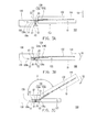
- FIGs. 3A-3C are diagrams illustrating an operation flow of a handheld electronic device of FIG. 1 .
- FIG. 4A and FIG. 4B are side views of a spread handheld electronic device of FIG. 1 .
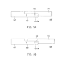
- FIG. 5A and FIG. 5B are side views of a spread handheld electronic device according to another embodiment of the present application.
- FIG. 1 is a three-dimensional diagram of a handheld electronic device according to an embodiment of the present application.
- FIG. 2 is a side perspective view of the handheld electronic device of FIG. 1 .
- the handheld electronic device 100 includes a first body 110, a second body 120 and a moving mechanism 130.
- the second body 120 is stacked under the first body 110, wherein a side of the second body 120 facing the first body 110 has a concave or recessed concave or recessed or recessed portion 122.
- the first body 110 and the second body 120 for example, respectively have a display screen and a keyboard of the handheld electronic device 100.
- the moving mechanism 130 includes a first sliding member 132, a second sliding member 134 and an elevating mechanism 136.
- the first sliding member 132 is fixed to the first body 110.
- the second sliding member 134 is slidingly disposed at the first sliding member 132.
- the elevating mechanism 136 is connected between the second body 120 and the second sliding member 134. After the first sliding member 132 is slid relatively to the second sliding member 134 to drive the first body 110 to shift relatively to the second body 120 to reach the concave or recessed portion 122, the first body 110 compresses the elevating mechanism 136 and enters the concave or recessed portion 122, such that a top surface of the first body 110 and a top surface of the second body 120 are substantially coplanar.
- FIG. 2 An operation flow of the handheld electronic device 100 is described in detail with reference of FIG. 2 , FIG. 3A to FIG. 3C .
- FIGs. 3A-3C are diagrams illustrating an operation flow of the handheld electronic device of FIG. 1 .
- the user pushes the first body 110 to a position shown in FIG. 3A along a direction D1.
- the first sliding member 132 is slid relatively to the second sliding member 134 to drive the first body 110 to shift relatively to the second body 120.
- the user can press down the first body 110 along a second direction D2 to compress the elevating mechanism 136, so that the first body 110 is descended to a position shown in FIG. 3B and enters the concave or recessed portion 122.
- the elevating mechanism 136 includes a first rod 136a and a second rod 136b.
- the first rod 136a has two first end parts E1 and a first pivot part P1 between the two first end parts E1, wherein the two first end parts E1 are respectively coupled to the first sliding member 132 and the second body 120.
- the second rod 136b has two second end parts E2 and a second pivot part P2 between the two second end parts E2, wherein the two second end parts E2 are respectively coupled to the first sliding member 132 and the second body 120, and the second pivot part P2 is pivotally connected to the first pivot part P1.
- the first rod 136a and the second rod 136b are pivotally rotated through the first pivot part P1 and the second pivot part P2, so that the elevating mechanism 136 can be smoothly actuated.
- the second sliding member 134 includes a first portion 134a and a second portion 134b.
- the first portion 134a is connected to the elevating mechanism 136.
- the second portion 134b is pivotally connected to the first portion 134a. Therefore, after the first body 110 enters the concave or recessed portion 122 (shown as FIG. 3B ), the user can wrench the first body 110, and the second portion 134b is pivotally rotated relatively to the first portion 134a to drive the first body 110 rotating relatively to the second body 120 along a direction R1 to a state shown as FIG. 3C , so that an angle A is formed between the top surface of the first body 110 and the top surface of the second body 120. In other words, the size of the angle A can be changed by rotating the first body 110 relatively to the second body 120, so as to adjust the display screen (the first body 110) to a suitable position for viewing.
- the moving mechanism 130 further includes a first elastic member S1 and a second elastic member S2.
- the first elastic member S1 is connected between the first sliding member 132 and the second sliding member 134.
- the first elastic member S1 of the present embodiment is, for example, a tension spring.
- the first elastic member S1 is elongated to store the elastic potential energy.
- the second elastic member S2 is connected between the second sliding member 134 and the second body 120.
- the second elastic member S2 is deformed to store elastic potential energy.
- the second elastic member S2 of the present embodiment is, for example, a compression spring.
- the second elastic member S2 is compressed to store the elastic potential energy.
- FIG. 4A and FIG. 4B are side views of a spread handheld electronic device of FIG. 1 .
- the first body 110 has a first positioning member 112
- the second body 120 has a second positioning member 124.
- the first positioning member 112 and the second positioning member 124 are mutually fixed to position the first body 110 at the concave or recessed portion 122, so as to maintain a spread state of the handheld electronic device 100.
- first positioning member 112 and the second positioning member 124 are, for example, magnetic members with different polarities, and are mutually attracted according to a magnetic attraction, though the present application is not limited thereto, and in other embodiments, the first positioning member 112 and the second positioning member 124 can also be fasteners coordinating with each other, and can be mutually fixed according to a structural interference.
- the handheld electronic device 100 further includes an unlock key 140.
- the unlock key 140 is disposed on the second body 120 and is connected to the second positioning member 124.
- the unlock key 140 is pushed to drive the second positioning member 124 to move from a position shown in FIG. 4A to a position shown in FIG. 4B , the first positioning member 112 and the second positioning member 124 are departed to unlock a fixing relation there between.
- a disposing position of the unlock key 140 is not limited by the present application, and in other embodiments, the unlock key 140 can also be disposed on the first body 110, and is connected to the first positioning member 112, so as to drive the first positioning member 112 to depart from the second positioning member 124.
- the elastic potential energy of the second elastic member S2 shown in FIG. 3B is released to elevate the first body 110 to a position shown in FIG. 3A .
- the first elastic member S1 is also released to shift the first body 110 to a position shown in FIG. 2 , so as to close the first body 110 to the second body 120.
- FIG. 5A and FIG. 5B are side views of a spread handheld electronic device according to another embodiment of the present application.
- a second body 120' of the handheld electronic device 100' of the present embodiment further has a third positioning member 126.
- the first positioning member 112 and the third positioning member 126 are magnetic members with a same polarity.
- the magnetic repulsion between the first positioning member 112 and the third positioning member 126 can function together with the elastic force of the second elastic member S2 (shown in FIG. 3B ) to drive the first body 110 departing from the concave or recessed portion 122.
- the first body and the second body are expanded, so that integrity of an appearance of the handheld electronic device is maintained. Relative sliding between the first body and the second body is driven by the first sliding member and the second sliding member, so that configuring of a sliding groove on the first body or the second body is unnecessary, and therefore the appearance of the handheld electronic device is more concise.
- the first body can be positioned at the concave or recessed portion through magnetic members or fasteners, so as to maintain a spread state of the handheld electronic device, and an angle formed between the first body and the second body can be changed by pivotally rotating the two portions of the second sliding member, so as to adjust the display screen of the handheld electronic device to a suitable position for viewing.
- the first body can be reposited and closed to the second body according to the elastic force of the elastic members, so as to improve an operation convenience of the handheld electronic device.
Landscapes
- Engineering & Computer Science (AREA)
- Signal Processing (AREA)
- Telephone Set Structure (AREA)
- Casings For Electric Apparatus (AREA)
Abstract
Description
- The present application relates to an electronic device. More particularly, the present application relates to a handheld electronic device.
- Along with development of information technology, obtaining required information from an electronic device becomes easier. On the other hand, with development of industrial engineering, various electronic devices have a general trend of lightness, slimness, shortness and smallness, and since the electronic devices have a feature and advantage of portability, they are widely used in people's daily life.
- Taking mobile phones as an example, to meet a requirement of portability and different preferences and demands, besides a conventional bar-type mobile phone, the mobile phones further include clamshell mobile phones, swivel mobile phones, and slide mobile phones, etc. Taking the slide mobile phone as an example, an upper body thereof is stacked over and can be slid relatively to a lower body thereof, so as to present different operation modes of open and close. Stacking the two bodies avails reducing a whole size of the mobile phone, and the two bodies can be spread during a specific operation mode.
- Taking a two-layer slide phone having a keyboard as an example, an operation method thereof is as follows. A display screen of the slide phone can be slid to a side of the keyboard to expose the keyboard, so as to facilitate a user to use the keyboard. However, in case of such design, after the display screen is slid relatively to the keyboard, a height difference is formed there between to present a step profile, so that an appearance of the slide phone is lack of integrity. Moreover, after the display screen is slid relatively to the keyboard, a sliding groove on the backside of the display screen is generally exposed to influence the appearance of the slide phone.
- The present application is directed to a handheld electronic device having an integral and concise appearance.
- The present application provides a handheld electronic device including a first body, a second body and a moving mechanism. The second body is stacked under the first body. A side of the second body facing the first body has a concave or recessed concave or recessed or recessed portion. The moving mechanism includes a first sliding member, a second sliding member and an elevating mechanism. The first sliding member is fixed to the first body. The second sliding member is slidingly disposed at the first sliding member. The elevating mechanism is connected between the second body and the second sliding member. After the first sliding member is slid relatively to the second sliding member to drive the first body to shift relatively to the second body to reach the concave or recessed concave or recessed or recessed portion, the first body compresses the elevating mechanism and enters the concave or recessed concave or recessed or recessed portion.
- Accordingly, after the first body is slid relatively to the second body, the first body enters the concave or recessed portion, so that the first body and the second body are expanded to maintain integrity of the appearance of the handheld electronic device. Moreover, relative sliding between the first body and the second body is driven by the first sliding member and the second sliding member, so that configuring of a sliding groove on the first body or the second body is unnecessary, and therefore the appearance of the handheld electronic device is concise.
- In order to make the aforementioned and other features and advantages of the present application comprehensible, several exemplary embodiments accompanied with figures are described in detail below.
- The accompanying drawings are included to provide a further understanding of the application, and are incorporated in and constitute a part of this specification. The drawings illustrate embodiments of the application and, together with the description, serve to explain the principles of the application.
-
FIG. 1 is a three-dimensional diagram of a handheld electronic device according to an embodiment of the present application. -
FIG. 2 is a side perspective view of a handheld electronic device ofFIG. 1 . -
FIGs. 3A-3C are diagrams illustrating an operation flow of a handheld electronic device ofFIG. 1 . -
FIG. 4A and FIG. 4B are side views of a spread handheld electronic device ofFIG. 1 . -
FIG. 5A and FIG. 5B are side views of a spread handheld electronic device according to another embodiment of the present application. - Reference will now be made in detail to the present preferred embodiments of the application, examples of which are illustrated in the accompanying drawings. Wherever possible, the same reference numbers are used in the drawings and the description to refer to the same or like parts.
-
FIG. 1 is a three-dimensional diagram of a handheld electronic device according to an embodiment of the present application.FIG. 2 is a side perspective view of the handheld electronic device ofFIG. 1 . Referring toFIG. 1 and FIG. 2 , the handheldelectronic device 100 includes afirst body 110, asecond body 120 and amoving mechanism 130. Thesecond body 120 is stacked under thefirst body 110, wherein a side of thesecond body 120 facing thefirst body 110 has a concave or recessed concave or recessed orrecessed portion 122. In the present embodiment, thefirst body 110 and thesecond body 120, for example, respectively have a display screen and a keyboard of the handheldelectronic device 100. - The
moving mechanism 130 includes a first slidingmember 132, a second slidingmember 134 and an elevating mechanism 136. The first slidingmember 132 is fixed to thefirst body 110. The second slidingmember 134 is slidingly disposed at the first slidingmember 132. The elevating mechanism 136 is connected between thesecond body 120 and the second slidingmember 134. After the first slidingmember 132 is slid relatively to the second slidingmember 134 to drive thefirst body 110 to shift relatively to thesecond body 120 to reach the concave orrecessed portion 122, thefirst body 110 compresses the elevating mechanism 136 and enters the concave orrecessed portion 122, such that a top surface of thefirst body 110 and a top surface of thesecond body 120 are substantially coplanar. - An operation flow of the handheld
electronic device 100 is described in detail with reference ofFIG. 2 ,FIG. 3A to FIG. 3C . -
FIGs. 3A-3C are diagrams illustrating an operation flow of the handheld electronic device ofFIG. 1 . Referring toFIG. 2 , when a user wants to operate the keyboard, the user pushes thefirst body 110 to a position shown inFIG. 3A along a direction D1. During such process, the first slidingmember 132 is slid relatively to the second slidingmember 134 to drive thefirst body 110 to shift relatively to thesecond body 120. Then, referring toFIG. 3A , the user can press down thefirst body 110 along a second direction D2 to compress the elevating mechanism 136, so that thefirst body 110 is descended to a position shown inFIG. 3B and enters the concave orrecessed portion 122. - Referring to
FIG. 2 , in detail, the elevating mechanism 136 includes afirst rod 136a and asecond rod 136b. Thefirst rod 136a has two first end parts E1 and a first pivot part P1 between the two first end parts E1, wherein the two first end parts E1 are respectively coupled to the first slidingmember 132 and thesecond body 120. Thesecond rod 136b has two second end parts E2 and a second pivot part P2 between the two second end parts E2, wherein the two second end parts E2 are respectively coupled to the first slidingmember 132 and thesecond body 120, and the second pivot part P2 is pivotally connected to the first pivot part P1. During a process when the elevating mechanism 136 is compressed from a state shown inFIG. 3A to a state shown inFIG. 3B , thefirst rod 136a and thesecond rod 136b are pivotally rotated through the first pivot part P1 and the second pivot part P2, so that the elevating mechanism 136 can be smoothly actuated. - Moreover, the second sliding
member 134 includes afirst portion 134a and asecond portion 134b. Thefirst portion 134a is connected to the elevating mechanism 136. Thesecond portion 134b is pivotally connected to thefirst portion 134a. Therefore, after thefirst body 110 enters the concave or recessed portion 122 (shown asFIG. 3B ), the user can wrench thefirst body 110, and thesecond portion 134b is pivotally rotated relatively to thefirst portion 134a to drive thefirst body 110 rotating relatively to thesecond body 120 along a direction R1 to a state shown asFIG. 3C , so that an angle A is formed between the top surface of thefirst body 110 and the top surface of thesecond body 120. In other words, the size of the angle A can be changed by rotating thefirst body 110 relatively to thesecond body 120, so as to adjust the display screen (the first body 110) to a suitable position for viewing. - Referring to
FIG. 2 , the movingmechanism 130 further includes a first elastic member S1 and a second elastic member S2. The first elastic member S1 is connected between the first slidingmember 132 and the second slidingmember 134. When the first slidingmember 132 is slid relatively to the second slidingmember 134 to drive thefirst body 110 to shift relatively to thesecond body 120 to reach the concave or recessedportion 122, the first elastic member S1 is deformed to store elastic potential energy. In detail, the first elastic member S1 of the present embodiment is, for example, a tension spring. During a process that thefirst body 110 is shifted from a position shown inFIG. 2 to a position shown inFIG. 3A , the first elastic member S1 is elongated to store the elastic potential energy. - The second elastic member S2 is connected between the second sliding
member 134 and thesecond body 120. When the elevating mechanism 136 is compressed, the second elastic member S2 is deformed to store elastic potential energy. In detail, the second elastic member S2 of the present embodiment is, for example, a compression spring. During a process that thefirst body 110 is descended from a position shown inFIG. 3A to a position shown inFIG. 3B , the second elastic member S2 is compressed to store the elastic potential energy. -
FIG. 4A and FIG. 4B are side views of a spread handheld electronic device ofFIG. 1 . Referring toFIG. 4A , in the present embodiment, thefirst body 110 has afirst positioning member 112, and thesecond body 120 has asecond positioning member 124. When thefirst body 110 enters the concave or recessedportion 122, thefirst positioning member 112 and thesecond positioning member 124 are mutually fixed to position thefirst body 110 at the concave or recessedportion 122, so as to maintain a spread state of the handheldelectronic device 100. In detail, thefirst positioning member 112 and thesecond positioning member 124 are, for example, magnetic members with different polarities, and are mutually attracted according to a magnetic attraction, though the present application is not limited thereto, and in other embodiments, thefirst positioning member 112 and thesecond positioning member 124 can also be fasteners coordinating with each other, and can be mutually fixed according to a structural interference. - Moreover, in the present embodiment, the handheld
electronic device 100 further includes anunlock key 140. Theunlock key 140 is disposed on thesecond body 120 and is connected to thesecond positioning member 124. When theunlock key 140 is pushed to drive thesecond positioning member 124 to move from a position shown inFIG. 4A to a position shown inFIG. 4B , thefirst positioning member 112 and thesecond positioning member 124 are departed to unlock a fixing relation there between. However, a disposing position of theunlock key 140 is not limited by the present application, and in other embodiments, theunlock key 140 can also be disposed on thefirst body 110, and is connected to thefirst positioning member 112, so as to drive thefirst positioning member 112 to depart from thesecond positioning member 124. - Referring to
FIG. 3C , when the user wants to close the handheldelectronic device 100, the user wrenches thefirst body 110 to pivotally rotating thesecond portion 134b relatively to thefirst portion 134a, so that thefirst body 110 is rotated relatively to thesecond body 120 along a direction R2 to a state shown inFIG. 3B , and the top surface of thefirst body 110 and the top surface of thesecond body 120 are recovered to the substantial coplanar state. Thereafter, referring toFIG. 4A , the user can push theunlock key 140 to drive thesecond positioning member 124 to move to a position shown inFIG. 4B for departing from thefirst positioning member 112, so that thefirst positioning member 112 and thesecond positioning member 124 are no longer mutually fixed by the magnetic attraction. Now, the elastic potential energy of the second elastic member S2 shown inFIG. 3B is released to elevate thefirst body 110 to a position shown inFIG. 3A . Then, the first elastic member S1 is also released to shift thefirst body 110 to a position shown inFIG. 2 , so as to close thefirst body 110 to thesecond body 120. -
FIG. 5A and FIG. 5B are side views of a spread handheld electronic device according to another embodiment of the present application. Referring toFIG. 5A , compared to the handheldelectronic device 100 ofFIG. 4A , a second body 120' of the handheld electronic device 100' of the present embodiment further has athird positioning member 126. Thefirst positioning member 112 and thethird positioning member 126 are magnetic members with a same polarity. When thefirst body 110 is shifted relatively to the second body 120' from a position shown inFIG. 5A to a position shown inFIG. 5B , thefirst body 110 is departed from the concave or recessedportion 122 according to a magnetic repulsion between thefirst positioning member 112 and thethird positioning member 126. In other words, the magnetic repulsion between thefirst positioning member 112 and thethird positioning member 126 can function together with the elastic force of the second elastic member S2 (shown inFIG. 3B ) to drive thefirst body 110 departing from the concave or recessedportion 122. - In summary, in the present application, after the first body is slid relatively to the second body to enter the concave or recessed portion, the first body and the second body are expanded, so that integrity of an appearance of the handheld electronic device is maintained. Relative sliding between the first body and the second body is driven by the first sliding member and the second sliding member, so that configuring of a sliding groove on the first body or the second body is unnecessary, and therefore the appearance of the handheld electronic device is more concise. Moreover, the first body can be positioned at the concave or recessed portion through magnetic members or fasteners, so as to maintain a spread state of the handheld electronic device, and an angle formed between the first body and the second body can be changed by pivotally rotating the two portions of the second sliding member, so as to adjust the display screen of the handheld electronic device to a suitable position for viewing. In addition, the first body can be reposited and closed to the second body according to the elastic force of the elastic members, so as to improve an operation convenience of the handheld electronic device.
- It will be apparent to those skilled in the art that various modifications and variations can be made to the structure of the present application without departing from the scope or spirit of the application. In view of the foregoing, it is intended that the present application cover modifications and variations of this application provided they fall within the scope of the following claims and their equivalents.
Claims (13)
- A handheld electronic device, comprising:a first body (110);a second body (120), stacked under the first body, wherein a side of the second body facing the first body has a concave or recessed portion (122);a moving mechanism (130), comprising:a first sliding member (132), fixed to the first body;a second sliding member (134), slidingly disposed at the first sliding member (132); andan elevating mechanism (136), connected between the second body (130) and the second sliding member (134), wherein after the first sliding member is slid relatively to the second sliding member to drive the first body to shift relatively to the second body to reach the concave or recessed portion (122), the first body (110) compresses the elevating mechanism (136) and enters the concave or recessed portion (122).
- The handheld electronic device as claimed in claim 1, wherein the moving mechanism further comprises:a first elastic member (S1), connected between the first sliding member (132) and the second sliding member (134), wherein when the first sliding member is slid relatively to the second sliding member to drive the first body to shift relatively to the second body to reach the concave or recessed portion (122), the first elastic member is deformed to store elastic potential energy.
- The handheld electronic device as claimed in claim 2, wherein the first elastic member (S1) is a tension spring.
- The handheld electronic device as claimed in any of the preceding claims, wherein the moving mechanism further comprises:a second elastic member (S2), connected between the second body (120) and the second sliding member (134), wherein when the elevating mechanism (136) is compressed, the second elastic member is deformed to store elastic potential energy.
- The handheld electronic device as claimed in claim 4, wherein the second elastic member (S2) is a compression spring.
- The handheld electronic device as claimed in any of the preceding claims, wherein the elevating mechanism (136) comprises:a first rod (136a), having two first end parts (E1) and a first pivot part (P1) between the two first end parts, wherein the two first end parts are respectively coupled to the first sliding member (132) and the second body (120); anda second rod (136b), having two second end parts (E2) and a second pivot part (P2) between the two second end parts, wherein the two second end parts are respectively coupled to the first sliding member (132) and the second body (120), and the second pivot part is pivotally connected to the first pivot part, and when the elevating mechanism is compressed, the first rod and the second rod are pivotally rotated through the first pivot part and the second pivot part.
- The handheld electronic device as claimed in any of the preceding claims, wherein the first body has a first positioning member (112), and the second body has a second positioning member (124), and when the first body enters the concave or recessed portion (122), the first positioning member and the second positioning member are mutually fixed to position the first body at the concave or recessed portion.
- The handheld electronic device as claimed in claim 7, wherein the first positioning member and the second positioning member are magnetic members with different polarities, and are mutually attracted according to a magnetic attraction.
- The handheld electronic device as claimed in claim 8, wherein the second body further has a third positioning member (126), the first positioning member and the third positioning member are magnetic members with a same polarity, and when the first body is shifted relatively to the second body to close the first positioning member to the third positioning member, the first body is departed from the concave or recessed portion according to a magnetic repulsion between the first positioning member and the third positioning member.
- The handheld electronic device as claimed in any of claims 7 to 9, wherein the first positioning member (122) and the second positioning member (124) are fasteners coordinating with each other, and are mutually fixed according to a structural interference.
- The handheld electronic device as claimed in any of claims 7 to 10, wherein the handheld electronic device further comprises:an unlock key (140), disposed on the first body or the second body and connected to the first positioning member or the second positioning member, wherein when the unlock key is pushed to drive the first positioning member or the second positioning member to move, the first positioning member and the second positioning member are departed to unlock a fixing relation between the first positioning member and the second positioning member.
- The handheld electronic device as claimed in any of the preceding claims, wherein a top surface of the first body (110) and a top surface of the second body (120) are substantially coplanar when the first body reaches the concave or recessed portion.
- The handheld electronic device as claimed in any of the preceding claims, wherein the second sliding member (134) comprises:a first portion (134a), connected to the elevating mechanism; anda second portion (134b), pivotally connected to the first portion, wherein after the first body enters the concave or recessed portion, the second portion is pivotally rotated relatively to the first portion to drive the first body rotating relatively to the second body, so that an angle is formed between the top surface of the first body and the top surface of the second body.
Applications Claiming Priority (1)
| Application Number | Priority Date | Filing Date | Title |
|---|---|---|---|
| TW098124589A TWI425906B (en) | 2009-07-21 | 2009-07-21 | Handheld electronic device |
Publications (2)
| Publication Number | Publication Date |
|---|---|
| EP2288118A1 true EP2288118A1 (en) | 2011-02-23 |
| EP2288118B1 EP2288118B1 (en) | 2012-08-15 |
Family
ID=41667161
Family Applications (1)
| Application Number | Title | Priority Date | Filing Date |
|---|---|---|---|
| EP09178563A Not-in-force EP2288118B1 (en) | 2009-07-21 | 2009-12-09 | Slidable handheld electronic device with elevating mechanism |
Country Status (3)
| Country | Link |
|---|---|
| US (1) | US8280464B2 (en) |
| EP (1) | EP2288118B1 (en) |
| TW (1) | TWI425906B (en) |
Families Citing this family (5)
| Publication number | Priority date | Publication date | Assignee | Title |
|---|---|---|---|---|
| US8136459B2 (en) * | 2010-08-08 | 2012-03-20 | Oakwood School | Desk with book holder |
| US8649166B2 (en) | 2011-01-11 | 2014-02-11 | Z124 | Multi-positionable portable computer |
| US8648821B2 (en) | 2011-01-18 | 2014-02-11 | Flextronics Id, Llc | Spheroidal pivot for an electronic device |
| US8526178B2 (en) * | 2011-05-17 | 2013-09-03 | Flextronics Ap, Llc | All-in-one computing device with an adjustable screen height |
| US8681113B1 (en) | 2011-09-27 | 2014-03-25 | Flextronics Ap, Llc | Concept and operation mode for multi media AIO |
Citations (4)
| Publication number | Priority date | Publication date | Assignee | Title |
|---|---|---|---|---|
| WO2006106374A1 (en) | 2005-04-06 | 2006-10-12 | Nokia Corporation | Extensible mobile electronic device |
| EP1843559A1 (en) | 2006-04-07 | 2007-10-10 | Samsung Electronics Co., Ltd. | Portable terminal including a sliding type cradle |
| WO2008080425A1 (en) | 2006-12-29 | 2008-07-10 | Nokia Corporation | Slidable housing for an electronic device |
| US20080307607A1 (en) | 2007-06-13 | 2008-12-18 | Min-Soo Kim | Portable terminal |
Family Cites Families (10)
| Publication number | Priority date | Publication date | Assignee | Title |
|---|---|---|---|---|
| US6980840B2 (en) * | 2000-01-24 | 2005-12-27 | Lg Electronics Inc. | Drawer-type mobile phone |
| FI118669B (en) * | 2003-04-01 | 2008-01-31 | Samsung Electro Mech | Sliding type mobile phone and its sliding method |
| JP4357900B2 (en) * | 2003-08-18 | 2009-11-04 | 加藤電機株式会社 | Slide hinge for small information terminal |
| WO2005020452A1 (en) * | 2003-08-25 | 2005-03-03 | M2Sys Co., Ltd | A sliding opening and closing device and a portable terminal having the same |
| KR100616197B1 (en) * | 2004-08-24 | 2006-08-25 | 삼성전자주식회사 | Sliding apparatus for double sliding-type portable communication device |
| KR100586979B1 (en) * | 2004-09-02 | 2006-06-08 | 삼성전기주식회사 | Automatic / Manual Slide Communication Terminal |
| DE602006012156D1 (en) * | 2005-11-30 | 2010-03-25 | Laird Technologies Map Co Ltd | Sliding mechanism for portable communication terminals |
| JP4963949B2 (en) | 2005-12-12 | 2012-06-27 | エルジー エレクトロニクス インコーポレイティド | Slide type mobile communication terminal |
| KR100790109B1 (en) * | 2006-11-09 | 2008-01-02 | 삼성전자주식회사 | Push rod and sliding type portable terminal therewith |
| TWM314873U (en) * | 2006-12-08 | 2007-07-01 | Wistron Corp | Adjustment device of display and portable computer and display having the same |
-
2009
- 2009-07-21 TW TW098124589A patent/TWI425906B/en not_active IP Right Cessation
- 2009-12-09 EP EP09178563A patent/EP2288118B1/en not_active Not-in-force
- 2009-12-10 US US12/635,669 patent/US8280464B2/en not_active Expired - Fee Related
Patent Citations (4)
| Publication number | Priority date | Publication date | Assignee | Title |
|---|---|---|---|---|
| WO2006106374A1 (en) | 2005-04-06 | 2006-10-12 | Nokia Corporation | Extensible mobile electronic device |
| EP1843559A1 (en) | 2006-04-07 | 2007-10-10 | Samsung Electronics Co., Ltd. | Portable terminal including a sliding type cradle |
| WO2008080425A1 (en) | 2006-12-29 | 2008-07-10 | Nokia Corporation | Slidable housing for an electronic device |
| US20080307607A1 (en) | 2007-06-13 | 2008-12-18 | Min-Soo Kim | Portable terminal |
Also Published As
| Publication number | Publication date |
|---|---|
| US20110018407A1 (en) | 2011-01-27 |
| TW201105220A (en) | 2011-02-01 |
| US8280464B2 (en) | 2012-10-02 |
| EP2288118B1 (en) | 2012-08-15 |
| TWI425906B (en) | 2014-02-01 |
Similar Documents
| Publication | Publication Date | Title |
|---|---|---|
| TWI255682B (en) | Sliding-type electronic device with a semi-automatic opening mechanism | |
| US8140135B2 (en) | Handheld electronic device | |
| US8634196B2 (en) | Locking mechanism and electronic device | |
| US8280464B2 (en) | Handheld electronic device | |
| US8254093B2 (en) | Sliding mechanism and electronic device having the same | |
| US8150483B2 (en) | Sliding mechanism and portable electronic device having the same | |
| US20130033802A1 (en) | Button assembly for electronic device | |
| US20060154619A1 (en) | Semi-automatic swing device for a mobile terminal | |
| EP2413576B1 (en) | Handheld electronic device | |
| US20070254691A1 (en) | Sliding mechanism for use with an electronic device | |
| CN101969481B (en) | handheld electronic device | |
| US8599553B2 (en) | Handheld electronic device | |
| US7725143B2 (en) | Spring loaded sliding cover for mobile phone or PDA | |
| EP2285074A1 (en) | Handheld electronic device and rising mechanism | |
| US8903461B2 (en) | Handheld electronic device | |
| US7492892B2 (en) | Slide opening/closing type mobile device | |
| KR100761527B1 (en) | Sliding device of mobile phone | |
| US8724316B2 (en) | Handheld electronic device | |
| KR100800711B1 (en) | Free stop hinge device of mobile terminal | |
| US20080259535A1 (en) | Sliding open/closed device | |
| CN201204772Y (en) | Sliding closure mechanism with semi-automatic opening and closing function | |
| KR101297013B1 (en) | Semi-automatic sliding unit for curved-sliding type mobile phone | |
| CN1988558A (en) | Sliding device for a portable device and portable phone | |
| KR100970470B1 (en) | Slide hinge device of the phone | |
| CN201146652Y (en) | A sliding mechanism and a portable electronic product using the sliding mechanism |
Legal Events
| Date | Code | Title | Description |
|---|---|---|---|
| PUAI | Public reference made under article 153(3) epc to a published international application that has entered the european phase |
Free format text: ORIGINAL CODE: 0009012 |
|
| 17P | Request for examination filed |
Effective date: 20091209 |
|
| AK | Designated contracting states |
Kind code of ref document: A1 Designated state(s): AT BE BG CH CY CZ DE DK EE ES FI FR GB GR HR HU IE IS IT LI LT LU LV MC MK MT NL NO PL PT RO SE SI SK SM TR |
|
| AX | Request for extension of the european patent |
Extension state: AL BA RS |
|
| GRAP | Despatch of communication of intention to grant a patent |
Free format text: ORIGINAL CODE: EPIDOSNIGR1 |
|
| GRAS | Grant fee paid |
Free format text: ORIGINAL CODE: EPIDOSNIGR3 |
|
| GRAA | (expected) grant |
Free format text: ORIGINAL CODE: 0009210 |
|
| AK | Designated contracting states |
Kind code of ref document: B1 Designated state(s): AT BE BG CH CY CZ DE DK EE ES FI FR GB GR HR HU IE IS IT LI LT LU LV MC MK MT NL NO PL PT RO SE SI SK SM TR |
|
| REG | Reference to a national code |
Ref country code: AT Ref legal event code: REF Ref document number: 571328 Country of ref document: AT Kind code of ref document: T Effective date: 20120815 Ref country code: GB Ref legal event code: FG4D Ref country code: CH Ref legal event code: EP |
|
| REG | Reference to a national code |
Ref country code: IE Ref legal event code: FG4D |
|
| REG | Reference to a national code |
Ref country code: DE Ref legal event code: R096 Ref document number: 602009008959 Country of ref document: DE Effective date: 20121011 |
|
| REG | Reference to a national code |
Ref country code: NL Ref legal event code: T3 |
|
| REG | Reference to a national code |
Ref country code: AT Ref legal event code: MK05 Ref document number: 571328 Country of ref document: AT Kind code of ref document: T Effective date: 20120815 |
|
| PG25 | Lapsed in a contracting state [announced via postgrant information from national office to epo] |
Ref country code: FI Free format text: LAPSE BECAUSE OF FAILURE TO SUBMIT A TRANSLATION OF THE DESCRIPTION OR TO PAY THE FEE WITHIN THE PRESCRIBED TIME-LIMIT Effective date: 20120815 Ref country code: NO Free format text: LAPSE BECAUSE OF FAILURE TO SUBMIT A TRANSLATION OF THE DESCRIPTION OR TO PAY THE FEE WITHIN THE PRESCRIBED TIME-LIMIT Effective date: 20121115 Ref country code: HR Free format text: LAPSE BECAUSE OF FAILURE TO SUBMIT A TRANSLATION OF THE DESCRIPTION OR TO PAY THE FEE WITHIN THE PRESCRIBED TIME-LIMIT Effective date: 20120815 Ref country code: LT Free format text: LAPSE BECAUSE OF FAILURE TO SUBMIT A TRANSLATION OF THE DESCRIPTION OR TO PAY THE FEE WITHIN THE PRESCRIBED TIME-LIMIT Effective date: 20120815 Ref country code: IS Free format text: LAPSE BECAUSE OF FAILURE TO SUBMIT A TRANSLATION OF THE DESCRIPTION OR TO PAY THE FEE WITHIN THE PRESCRIBED TIME-LIMIT Effective date: 20121215 Ref country code: AT Free format text: LAPSE BECAUSE OF FAILURE TO SUBMIT A TRANSLATION OF THE DESCRIPTION OR TO PAY THE FEE WITHIN THE PRESCRIBED TIME-LIMIT Effective date: 20120815 |
|
| PG25 | Lapsed in a contracting state [announced via postgrant information from national office to epo] |
Ref country code: LV Free format text: LAPSE BECAUSE OF FAILURE TO SUBMIT A TRANSLATION OF THE DESCRIPTION OR TO PAY THE FEE WITHIN THE PRESCRIBED TIME-LIMIT Effective date: 20120815 Ref country code: SE Free format text: LAPSE BECAUSE OF FAILURE TO SUBMIT A TRANSLATION OF THE DESCRIPTION OR TO PAY THE FEE WITHIN THE PRESCRIBED TIME-LIMIT Effective date: 20120815 Ref country code: GR Free format text: LAPSE BECAUSE OF FAILURE TO SUBMIT A TRANSLATION OF THE DESCRIPTION OR TO PAY THE FEE WITHIN THE PRESCRIBED TIME-LIMIT Effective date: 20121116 Ref country code: PL Free format text: LAPSE BECAUSE OF FAILURE TO SUBMIT A TRANSLATION OF THE DESCRIPTION OR TO PAY THE FEE WITHIN THE PRESCRIBED TIME-LIMIT Effective date: 20120815 Ref country code: SI Free format text: LAPSE BECAUSE OF FAILURE TO SUBMIT A TRANSLATION OF THE DESCRIPTION OR TO PAY THE FEE WITHIN THE PRESCRIBED TIME-LIMIT Effective date: 20120815 Ref country code: BE Free format text: LAPSE BECAUSE OF FAILURE TO SUBMIT A TRANSLATION OF THE DESCRIPTION OR TO PAY THE FEE WITHIN THE PRESCRIBED TIME-LIMIT Effective date: 20120815 Ref country code: PT Free format text: LAPSE BECAUSE OF FAILURE TO SUBMIT A TRANSLATION OF THE DESCRIPTION OR TO PAY THE FEE WITHIN THE PRESCRIBED TIME-LIMIT Effective date: 20121217 |
|
| PG25 | Lapsed in a contracting state [announced via postgrant information from national office to epo] |
Ref country code: RO Free format text: LAPSE BECAUSE OF FAILURE TO SUBMIT A TRANSLATION OF THE DESCRIPTION OR TO PAY THE FEE WITHIN THE PRESCRIBED TIME-LIMIT Effective date: 20120815 Ref country code: ES Free format text: LAPSE BECAUSE OF FAILURE TO SUBMIT A TRANSLATION OF THE DESCRIPTION OR TO PAY THE FEE WITHIN THE PRESCRIBED TIME-LIMIT Effective date: 20121126 Ref country code: EE Free format text: LAPSE BECAUSE OF FAILURE TO SUBMIT A TRANSLATION OF THE DESCRIPTION OR TO PAY THE FEE WITHIN THE PRESCRIBED TIME-LIMIT Effective date: 20120815 Ref country code: DK Free format text: LAPSE BECAUSE OF FAILURE TO SUBMIT A TRANSLATION OF THE DESCRIPTION OR TO PAY THE FEE WITHIN THE PRESCRIBED TIME-LIMIT Effective date: 20120815 Ref country code: CZ Free format text: LAPSE BECAUSE OF FAILURE TO SUBMIT A TRANSLATION OF THE DESCRIPTION OR TO PAY THE FEE WITHIN THE PRESCRIBED TIME-LIMIT Effective date: 20120815 |
|
| PG25 | Lapsed in a contracting state [announced via postgrant information from national office to epo] |
Ref country code: SK Free format text: LAPSE BECAUSE OF FAILURE TO SUBMIT A TRANSLATION OF THE DESCRIPTION OR TO PAY THE FEE WITHIN THE PRESCRIBED TIME-LIMIT Effective date: 20120815 Ref country code: IT Free format text: LAPSE BECAUSE OF FAILURE TO SUBMIT A TRANSLATION OF THE DESCRIPTION OR TO PAY THE FEE WITHIN THE PRESCRIBED TIME-LIMIT Effective date: 20120815 |
|
| PLBE | No opposition filed within time limit |
Free format text: ORIGINAL CODE: 0009261 |
|
| STAA | Information on the status of an ep patent application or granted ep patent |
Free format text: STATUS: NO OPPOSITION FILED WITHIN TIME LIMIT |
|
| 26N | No opposition filed |
Effective date: 20130516 |
|
| PG25 | Lapsed in a contracting state [announced via postgrant information from national office to epo] |
Ref country code: BG Free format text: LAPSE BECAUSE OF FAILURE TO SUBMIT A TRANSLATION OF THE DESCRIPTION OR TO PAY THE FEE WITHIN THE PRESCRIBED TIME-LIMIT Effective date: 20121115 Ref country code: MC Free format text: LAPSE BECAUSE OF NON-PAYMENT OF DUE FEES Effective date: 20121231 |
|
| REG | Reference to a national code |
Ref country code: DE Ref legal event code: R097 Ref document number: 602009008959 Country of ref document: DE Effective date: 20130516 |
|
| REG | Reference to a national code |
Ref country code: IE Ref legal event code: MM4A |
|
| PG25 | Lapsed in a contracting state [announced via postgrant information from national office to epo] |
Ref country code: IE Free format text: LAPSE BECAUSE OF NON-PAYMENT OF DUE FEES Effective date: 20121209 |
|
| PG25 | Lapsed in a contracting state [announced via postgrant information from national office to epo] |
Ref country code: MT Free format text: LAPSE BECAUSE OF FAILURE TO SUBMIT A TRANSLATION OF THE DESCRIPTION OR TO PAY THE FEE WITHIN THE PRESCRIBED TIME-LIMIT Effective date: 20120815 Ref country code: CY Free format text: LAPSE BECAUSE OF FAILURE TO SUBMIT A TRANSLATION OF THE DESCRIPTION OR TO PAY THE FEE WITHIN THE PRESCRIBED TIME-LIMIT Effective date: 20120815 |
|
| PG25 | Lapsed in a contracting state [announced via postgrant information from national office to epo] |
Ref country code: TR Free format text: LAPSE BECAUSE OF FAILURE TO SUBMIT A TRANSLATION OF THE DESCRIPTION OR TO PAY THE FEE WITHIN THE PRESCRIBED TIME-LIMIT Effective date: 20120815 |
|
| PG25 | Lapsed in a contracting state [announced via postgrant information from national office to epo] |
Ref country code: SM Free format text: LAPSE BECAUSE OF FAILURE TO SUBMIT A TRANSLATION OF THE DESCRIPTION OR TO PAY THE FEE WITHIN THE PRESCRIBED TIME-LIMIT Effective date: 20120815 Ref country code: LU Free format text: LAPSE BECAUSE OF NON-PAYMENT OF DUE FEES Effective date: 20121209 |
|
| PG25 | Lapsed in a contracting state [announced via postgrant information from national office to epo] |
Ref country code: HU Free format text: LAPSE BECAUSE OF FAILURE TO SUBMIT A TRANSLATION OF THE DESCRIPTION OR TO PAY THE FEE WITHIN THE PRESCRIBED TIME-LIMIT Effective date: 20091209 |
|
| REG | Reference to a national code |
Ref country code: CH Ref legal event code: PL |
|
| PG25 | Lapsed in a contracting state [announced via postgrant information from national office to epo] |
Ref country code: LI Free format text: LAPSE BECAUSE OF NON-PAYMENT OF DUE FEES Effective date: 20131231 Ref country code: CH Free format text: LAPSE BECAUSE OF NON-PAYMENT OF DUE FEES Effective date: 20131231 |
|
| PG25 | Lapsed in a contracting state [announced via postgrant information from national office to epo] |
Ref country code: MK Free format text: LAPSE BECAUSE OF FAILURE TO SUBMIT A TRANSLATION OF THE DESCRIPTION OR TO PAY THE FEE WITHIN THE PRESCRIBED TIME-LIMIT Effective date: 20120815 |
|
| REG | Reference to a national code |
Ref country code: FR Ref legal event code: PLFP Year of fee payment: 7 |
|
| REG | Reference to a national code |
Ref country code: FR Ref legal event code: PLFP Year of fee payment: 8 |
|
| REG | Reference to a national code |
Ref country code: FR Ref legal event code: PLFP Year of fee payment: 9 |
|
| PGFP | Annual fee paid to national office [announced via postgrant information from national office to epo] |
Ref country code: DE Payment date: 20181127 Year of fee payment: 10 Ref country code: NL Payment date: 20181213 Year of fee payment: 10 |
|
| PGFP | Annual fee paid to national office [announced via postgrant information from national office to epo] |
Ref country code: GB Payment date: 20181205 Year of fee payment: 10 Ref country code: FR Payment date: 20181120 Year of fee payment: 10 |
|
| REG | Reference to a national code |
Ref country code: DE Ref legal event code: R119 Ref document number: 602009008959 Country of ref document: DE |
|
| REG | Reference to a national code |
Ref country code: NL Ref legal event code: MM Effective date: 20200101 |
|
| GBPC | Gb: european patent ceased through non-payment of renewal fee |
Effective date: 20191209 |
|
| PG25 | Lapsed in a contracting state [announced via postgrant information from national office to epo] |
Ref country code: NL Free format text: LAPSE BECAUSE OF NON-PAYMENT OF DUE FEES Effective date: 20200101 |
|
| PG25 | Lapsed in a contracting state [announced via postgrant information from national office to epo] |
Ref country code: FR Free format text: LAPSE BECAUSE OF NON-PAYMENT OF DUE FEES Effective date: 20191231 Ref country code: GB Free format text: LAPSE BECAUSE OF NON-PAYMENT OF DUE FEES Effective date: 20191209 Ref country code: DE Free format text: LAPSE BECAUSE OF NON-PAYMENT OF DUE FEES Effective date: 20200701 |