EP2288063A1 - Data processing in an optical network - Google Patents
Data processing in an optical network Download PDFInfo
- Publication number
- EP2288063A1 EP2288063A1 EP09010758A EP09010758A EP2288063A1 EP 2288063 A1 EP2288063 A1 EP 2288063A1 EP 09010758 A EP09010758 A EP 09010758A EP 09010758 A EP09010758 A EP 09010758A EP 2288063 A1 EP2288063 A1 EP 2288063A1
- Authority
- EP
- European Patent Office
- Prior art keywords
- wavelengths
- laser
- optical
- collision
- optical component
- Prior art date
- Legal status (The legal status is an assumption and is not a legal conclusion. Google has not performed a legal analysis and makes no representation as to the accuracy of the status listed.)
- Granted
Links
- 230000003287 optical effect Effects 0.000 title claims abstract description 87
- 238000012545 processing Methods 0.000 title claims abstract description 11
- 238000000034 method Methods 0.000 claims abstract description 21
- 230000006854 communication Effects 0.000 claims abstract description 7
- 238000004891 communication Methods 0.000 claims abstract description 7
- 238000001514 detection method Methods 0.000 claims description 29
- 238000011144 upstream manufacturing Methods 0.000 claims description 14
- 230000005540 biological transmission Effects 0.000 claims description 7
- 238000012544 monitoring process Methods 0.000 claims description 5
- 238000013459 approach Methods 0.000 description 12
- 238000010586 diagram Methods 0.000 description 7
- 238000005516 engineering process Methods 0.000 description 4
- 239000000835 fiber Substances 0.000 description 4
- 230000007246 mechanism Effects 0.000 description 3
- 238000012546 transfer Methods 0.000 description 3
- VYPSYNLAJGMNEJ-UHFFFAOYSA-N Silicium dioxide Chemical compound O=[Si]=O VYPSYNLAJGMNEJ-UHFFFAOYSA-N 0.000 description 2
- 238000012423 maintenance Methods 0.000 description 2
- 238000001228 spectrum Methods 0.000 description 2
- 230000003321 amplification Effects 0.000 description 1
- 230000007175 bidirectional communication Effects 0.000 description 1
- 230000003139 buffering effect Effects 0.000 description 1
- 239000000969 carrier Substances 0.000 description 1
- 230000001427 coherent effect Effects 0.000 description 1
- 239000003086 colorant Substances 0.000 description 1
- 230000023077 detection of light stimulus Effects 0.000 description 1
- 230000004069 differentiation Effects 0.000 description 1
- 238000003199 nucleic acid amplification method Methods 0.000 description 1
- 239000013307 optical fiber Substances 0.000 description 1
- 239000000377 silicon dioxide Substances 0.000 description 1
- 239000002699 waste material Substances 0.000 description 1
Images


Classifications
-
- H—ELECTRICITY
- H04—ELECTRIC COMMUNICATION TECHNIQUE
- H04J—MULTIPLEX COMMUNICATION
- H04J14/00—Optical multiplex systems
- H04J14/02—Wavelength-division multiplex systems
- H04J14/0221—Power control, e.g. to keep the total optical power constant
Definitions
- the invention relates to a method and to a device for data processing in an optical network and to an optical network comprising such a device.
- a passive optical network is a promising approach regarding fiber-to-the-home (FTTH), fiber-to-the-business (FTTB) and fiber-to-the-curb (FTTC) scenarios, in particular as it overcomes the economic limitations of traditional point-to-point solutions.
- FTTH fiber-to-the-home
- FTTB fiber-to-the-business
- FTTC fiber-to-the-curb
- the PON has been standardized and it is currently being deployed by network service providers worldwide.
- Conventional PONs distribute downstream traffic from the optical line terminal (OLT) to optical network units (ONUs) in a broadcast manner while the ONUs send upstream data packets multiplexed in time to the OLT.
- OLT optical line terminal
- ONUs optical network units
- communication among the ONUs needs to be conveyed through the OLT involving electronic processing such as buffering and/or scheduling, which results in latency and degrades the throughput of the network.
- wavelength-division multiplexing is a technology which multiplexes multiple optical carrier signals on a single optical fiber by using different wavelengths (colors) of laser light to carry different signals. This allows for a multiplication in capacity, in addition to enabling bidirectional communications over one strand of fiber.
- WDM systems are divided into different wavelength patterns, conventional or coarse and dense WDM.
- WDM systems provide, e.g., up to 16 channels in the 3rd transmission window (C-band) of silica fibers around 1550 nm.
- Dense WDM uses the same transmission window but with denser channel spacing.
- Channel plans vary, but a typical system may use 40 channels at 100 GHz spacing or 80 channels with 50 GHz spacing. Some technologies are capable of 25 GHz spacing.
- Amplification options enable the extension of the usable wavelengths to the L-band, more or less doubling these numbers.
- Optical access networks e.g., a coherent Ultra-Dense Wavelength Division Multiplex (UDWDM) network, are deemed to be the future data access technology.
- UDWDM Ultra-Dense Wavelength Division Multiplex
- the respective wavelength is selected by the tuning of the local oscillator (LO) laser at the ONU.
- LO local oscillator
- Fig.1 shows a UDWDM optical access system deployed with an optical line terminal (OLT) 115.
- the OLT 115 comprises three linecards (also referred to as line interface card, LIC) 101, 102, 103.
- the linecard 101 comprises two optical transmission groups (OTGs) 104, 105 that are connected to a splitter 106 and the output of the splitter 106 is connected to a power splitter 113. Accordingly, OTGs 107, 108 of the LIC 102 are combined via a splitter 109 towards said power splitter 113 and OTGs 110, 111 of the LIC 103 are combined via a splitter 112 towards said power splitter 113.
- the power splitter 113 is connected to a PON 114.
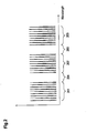
- FIG.2 shows a diagram of an optical spectrum comprising a combination of OTGs, wherein a set of wavelengths 201 is generated by a first OTG, a set of wavelength 202 is generated by a second OTG and a set of wavelengths 203 is generated by a third OTG.
- Wavelengths from several OTGs can be combined onto a single fiber.
- wavelengths from several LICs can be combined onto a single fiber.
- the wavelengths of the OTGs are separated by guard bands 204, 205 allowing frequency drifts of each set of wavelengths 201, 202, 203 without interference with its adjacent group of wavelengths.
- a single UDWDM system may serve more than 1000 subscribers, but due to today's technology, an OTG in an OLT may be capable of handling only a significantly smaller amount of subscribers. Therefore, multiple OTGs are required to cope with a larger number of subscribers in a PON. As indicated in Fig.1 , the OTGs are combined by the power splitter 113.
- Tunable linecards i.e. linecards with tunable lasers
- Tunable linecards are a promising option, as they avoid high operational expenditure (OPEX): Hence, there is no need for managing multiple types of linecards with one particular linecard type for each wavelength range.
- Low-cost tunable lasers could be used in the linecards to make them adjustable to wavelengths and at the same time meet the requirement for an overall cost efficiency of such linecards.
- such low-cost tunable lasers show a significant degree of drift and tolerances. Such drift may result in one OTG colliding with the wavelength range of another OTG (collision of wavelength ranges of different OTGs) and the signals of both OTGs would thus be degraded leading to a service disruption that may be perceivable for the subscribers.
- the problem to be solved is to overcome the disadvantages stated above and in particular to provide a cost-efficient solution to (at least partially) compensate tolerances and drifts of a laser in an optical component.
- adjusting the laser may in particular include adjusting a wavelength of said laser.
- the laser may be used as a local oscillator laser, in particular a CW laser, of the optical component.
- a set of wavelengths may be monitored by monitoring a wavelength range or frequency band around this set of wavelengths.
- the breadth of such band can be defined according to a band gap that is required to avoid any collision between several sets of wavelengths. For example, if the breadth of the band is set to a particular size, an imminent collision can be detected once the sets of wavelengths approach each other and the gap between those sets runs below said size.
- a set of wavelengths may comprise at least one wavelength range or band that can be used for communication purposes.
- a number of wavelengths can be used as one such set of wavelengths, wherein all wavelengths of this group are generated by a single laser.
- shifting the laser's wavelength results in shifting all wavelengths of this set of wavelengths.
- the set of wavelengths may in particular be provided by an optical transmission group (OTG), wherein at least one such OTG can be deployed with a linecard of an ONU or an OLT.
- OTG optical transmission group
- wavelength range may refer to any continuous or non-continuous band of wavelengths or frequencies that may be utilized for communication purposes.
- a drift of the sets of wavelengths towards (or apart from) each other can be detected. If this is the case, the collision can be avoided by tuning one of the laser thereby adjusting the wavelengths of the set of wavelengths that is associated with this laser.
- the collision can be detected, e.g., if the distance between two sets of wavelength falls below a predetermined threshold (gap band).
- the collision being avoided refers to the scenario when the collision will not occur as the adjustment is timely made prior to the collision as well as to the scenario when the collision occurs, but is (quickly) reduced or compensated by adjusting the at least one laser of the optical component.
- the ONUs may follow the downstream wavelengths.
- the optical component is or is associated with one of the following:
- each set of wavelengths is associated with one laser of an optical component, in particular with an optical transmission group (OTG).
- OTG optical transmission group
- the collision is avoided or compensated by determining an optical gap between the at least two sets of wavelengths and by adjusting at least one laser of an optical component when the optical gap reaches a predetermined threshold.
- the laser of the optical component is tuned such that a minimum optical gap between the sets of wavelengths is complied with.
- a collision can be detected in advance and a countermeasure can be taken before the actual collision. This effectively avoids any collision between sets of wavelengths to occur.
- a downstream laser signal of the optical component is mixed with an upstream light of at least one adjacent optical component and a collision detection signal is determined by the optical component based on this mixed signal.
- the collision detection signal allows detection of light at a wavelength larger than the wavelength range occupied by the set of wavelengths of the optical component and may indicate a collision (or an imminent collision) when a further set of wavelengths approaches this set of wavelengths.
- the downstream laser signal is in particular an unmodulated laser signal.
- downstream laser signals of several optical components are mixed to a collision detection signal.
- said collision detection signal is fed to a centralized collision detection device.
- a centralized collision detection device According to an embodiment, several centralized collision detection devices are provided in parallel, in particular for shared processing and/or for redundancy purposes.
- the collision detection signal indicates an intermediate frequency corresponding to an optical distance of both sets of wavelengths.
- the collision can be detected and signaled by the collision detection device.
- an optical network unit scans downstream signals of several sets of wavelengths and determines a collision detection signal.
- Such ONU may be construed and/or set up to scan for downstream signal
- the optical network unit determines a distance between two adjacent wavelengths of a set of wavelengths and a distance between two sets of wavelengths and determines a collision if the distance between the two sets of wavelengths is less than the distance between two adjacent wavelengths of the set of wavelengths.
- an imminent collision can be detected as well, e.g., by including a safeguard gap band (added to the distance between two sets of wavelengths) and therefore triggering a collision avoidance sequence prior to the actual collision occurrence.
- the optical network unit transmits the collision detection signal upstream to an optical access point, in particular to an optical line termination.
- the ONU may utilize a free or reserved wavelength or it may use a separate channel, e.g., a connection over a different network like the Ethernet.
- a downstream laser signal of the optical component is mixed with a downstream light of at least one adjacent optical component and wherein a collision detection signal is determined by the optical component based on this mixed signal.
- the collision detection signal may comprise an intermodulation between the laser signal and the downstream signals of the at least one adjacent optical component.
- the collision detection signal may comprise an intermodulation between different sets of wavelengths of the at least one adjacent (or other) optical component.
- the two sets of wavelengths comprise a first set of wavelengths that is associated with a first laser and a second set of wavelengths that is associated with a second laser; and the second set of wavelengths is tuned via the second laser towards the first set of wavelengths.
- the second laser can be tuned to iteratively or continuously move the second set of wavelengths towards the first set of wavelengths.
- a device comprising and/or being associated with a processing unit and/or a hard-wired circuit and/or a logic device that is arranged such that the method as described herein is executable thereon.
- said monitoring of the set of wavelengths may comprise monitoring a wavelength range around this set of wavelengths to become aware of an imminent collision before this collision actually occurs.
- optical communication system comprising at least one optical component as described herein.
- the approach provided allows using tunable lasers in an optical linecard without any need for a temperature control.
- the mechanism described here allows the linecard lasers to drift as long as a wavelength range of a specific OTG does not reach or interfere with a wavelength range of an adjacent OTG. In case the wavelength ranges of OTGs drift towards each other, an imminent collision can be detected and at least one OTG can be tuned slightly to avoid such collision.
- An OTG can serve k wavelengths, i.e. k subscribers. If less than k subscribers are active in a specific PON, a single OTG is powered up. In this case no collision with further OTGs occur and the laser of the linecard may be tuned to an upper (or a lower) end of its wavelength tuning range.
- the OLT activates the next OTG.
- This new OTG may utilize wavelengths at the opposite end of the wavelength tuning range and it may be tuned towards the first OTG.
- the new OTG may continuously monitor collisions and it may stop tuning when a collision is detected or imminent. At this wavelength range (prior to such a collision to occur), the new OTG has found its wavelength range and starts accepting login events from ONUs.
- each OTG comprises a Collision Detection Device (CDD), which may be part of the multi-channel-receiver of the OTG.
- CDD Collision Detection Device
- Fig.6 shows steps of a method that can be applied to efficiently utilize a bandwidth range by several optical components, e.g., OTGs.
- a first OTG is powered up. This first OTG allocates a set of wavelengths (a wavelength range or band) at or near an end of a tuning range (step 602). This could be at the upper or lower end of the available band. The first OTG may then utilize this set of wavelengths by allowing ONUs to log onto it.
- a next (here: second) OTG is powered up. In order to initially avoid any overlap of the set of wavelengths used by this second OTG with the set of wavelengths already allocated by the first OTG, the second OTG allocates a set of wavelengths at or near an opposite side of the tuning range (step 604).
- the second OTG may then shift the set of wavelengths (by tuning its laser) towards the other end of the tuning range (step 605).
- the second OTG e.g., via its CDD
- detects an imminent collision e.g., approaching the set of wavelengths of the first OTG by falling below a band gap of 3 GHz.
- the predetermined band gap between the sets of wavelengths can be used to efficiently utilize the tuning range.
- the second OTG utilizes these wavelengths that are close to the set of wavelengths of the first OTG, but sufficiently remote to avoid any interference or collision.
- the second OTG may allow ONUs to log onto the wavelengths allocated (step 606).
- Fig.3 shows a schematic block diagram of an OTG that is connected to a PON.
- a laser 308 conveys its signal to the modulator 307 and is used as a local oscillator for modulating the signals of the combiner 302.
- the output of the modulator 307 is fed to a circulator 309 which conveys outgoing signals towards a PON 318.
- Incoming signals are fed from the PON 318 to the circulator 309 and further together with the signal of the laser 308 to a photodiode 310.
- the signal is separated by a filter 311, in particular by a set of electrical bandpass filters into several channels 312 to 315, wherein one signal is determined as a collision detection signal 316, which is fed to and evaluated by a collision detection device 317.
- the laser 308 may be an unmodulated continuous-wave (CW) laser.
- the signal of the laser 308 is used as local oscillator for the heterodyne receiver by the photodiode 310.
- the photodiode 310 converts the optical signal into an electrical signal comprising a sum of all upstream signals, in this example the signal of the channels 312 to 315.
- the (electrical) filter separates the different upstream signal from each other.
- the CDD 317 reacts on upstream light that is provided by at least one ONU, which that is logged in to a neighbor linecard. For example, if the wavelength range of a linecard amounts to +/- 10 GHz, the CDD 317 is capable to detect light at +/-12 GHz. Therefore the CDD 317 can trigger a signal 2 GHz before an actual collision occurs.
- both the first and the second linecards may drift. If a new collision occurs or is imminent, the second linecard can be tuned away from the first linecard (i.e. a second set of wavelengths utilized by the second linecard can be adjusted such that a predetermined band gap to a first set of wavelengths utilized by the first linecard is maintained; as each set of wavelengths is associated with a laser setting, this laser can be tuned to adjust the band gap between two sets of wavelengths). It may not be possible to tune the first linecard, because the first linecard may utilize wavelengths at the end of a tuning range, as indicated above.
- the ONUs that are logged to this second linecard may follow the linecard and no traffic disruption occurs. Therefore, the tuning or adjustment of the wavelength range has to be conducted at a slow speed to allow the ONUs to follow such adjustment.
- the OLT may activate the next linecard following the same scheme.
- tuning of the second linecard may inflict a collision between the second and a third linecard, which may result in a tuning of the third linecard as well.
- the OLT may stop tuning of the lower number linecard(s) until the tuning of the higher number linecard(s) is completed.
- the OLT may tune the linecards towards each other until a collision is imminent or detected. This guarantees an optimized, e.g., minimum, spacing between the sets of wavelengths used by the linecards.
- the highest and the lowest wavelength of a linecard are occupied to allow the neighboring linecards to detect the collision, because the collision detector needs the upstream light to detect a collision. If a subscriber disconnects from such an outer wavelength, another subscriber may thus advantageously be moved to this outer wavelength to guarantee the efficient operation of the collision detectors. This subscriber to be moved can be taken from the linecard with the highest number. If this linecard is "empty", i.e. without any subscribers logged on to it the linecard with the highest number can be deactivated.
- the CDD can be implemented in various ways.
- One exemplary realization comprises a peak signal detector.
- the same collision detection channel can detect a collision with an upper and a lower neighboring linecard.
- the CDD may not be able to decide by itself whether the collision happens at the upper or the lower end of the wavelength range. Therefore the OLT may combine the collision detect signals from several (all) of its OTGs to make such a decision. If, for example, a collision is signaled by both OTG4 and OTG5, the collision occurred between OTG4 and OTG5.
- An alternative method is to use a heterodyne receiver mixing downstream signals from different OTGs.
- each OTG has a separate output for the unmodulated laser signal. All of these outputs are combined with power splitters and guided to a separate CDD.
- the CDD comprises a photodiode, a filter, a rectifier and a threshold detector. Whenever sets of wavelengths of two OTGs collide, the photodiode mixes the corresponding OTG laser signals and produces an intermediate frequency corresponding to the optical distance of both OTGs. The CDD detects this intermediate frequency and signals a collision.
- the CDD is a single source of failure for the OLT.
- the OLT may be equipped with two or more CDDs.
- Fig.4 shows a block diagram visualizing an OLT 404 comprising three linecards 101, 102 and 103 combined by a power splitter as shown and described in Fig.1 .
- the OLT 404 comprises two CDDs 401, 402. One CDD is provided for redundancy purposes.
- the CDDs 401, 402 are combined via a splitter 403; the linecards 101 to 103 and the CDDs are combined via a splitter 406 and are connected to a PON 405.
- an ONU can be used to (iteratively, repeatedly and/or permanently) scan the complete wavelength range.
- Each ONU can act as a spectrum analyzer due to its tunable laser and heterodyne receiver.
- the ONU's laser may have the same or even a larger drift or higher tolerances than the laser of the OTG. Therefore, the ONU may not determine the absolute position of the OTG's downstream signals. Nevertheless the ONU can determine the relative position between OTGs.
- the ONU may scan the complete wavelength range at a constant tuning speed. Whenever it scans over the wavelength bundle of an OTG it calibrates its tuning position by logging the wavelength IDs, which are contained in the Almanac signals of every downstream wavelength. Additionally it knows the fixed distance between two adjacent wavelengths of one OTG (for example 3 GHz) and can simply compare such a distance inside an OTG with the distance between two OTGs. As long as the distance between two OTGs is larger than the distance inside an OTG, no collision occurs.
- This dedicated ONU may have to transfer its results of the scanning process to the OLT, which can be done utilizing at least one of the following mechanisms:
- an unmodulated downstream signal of the OTG is fed to a further heterodyne receiver.
- a tributary port of the PON is fed to the same receiver; hence, a photodiode of this receiver obtains all downstream signals of all OTGs as well as a signal of its own laser.
- Fig.5 shows a schematic block diagram of an OTG 504 that is connected to a PON 318.
- the OTG 504 is based on the OTG 301 as shown in Fig.3 and explained above.
- Fig.5 shows a separate photodiode 501 that is fed by the laser 308 and via the PON 318 thereby receiving all upstream signals of various OTGs.
- the output 502 of the photodiode 501 is fed to a CDD 503.
- Intermediate frequencies that are visible at the electrical port of the photodiode 502 can be based on one of the following:
- the laser 308 may have a significantly higher amplitude at the photodiode 501 than any downstream signal from an OTG. This can be achieved by the inherent attenuation of the PON. If the splitting ratio of the PON is very low, the power level at the OTG collision input 505 may be reduced by an attenuator.
- the intermodulation between the local laser 308 and OTG signal from the PON has a higher amplitude than any intermodulation between OTG signals received at the photodiode 501. Hence, the intermodulation between the local laser 308 and the OTG signal can be detected at the CDD 503.
- a differentiation between these intermodulations can be achieved via frequency:
- the intermodulation with the own downstream signals occurs at fixed frequencies. For example if the OTG has a bandwidth of +/- 10 GHz, all of these intermodulations have a frequency below 10 GHz.
- Any collision with a neighboring OTG could be defined as an event, when a guard band between two OTGs is reduced to 3 GHz or less.
- the intermodulation frequency is 13 GHz in case of a collision.
Abstract
Description
- The invention relates to a method and to a device for data processing in an optical network and to an optical network comprising such a device.
- A passive optical network (PON) is a promising approach regarding fiber-to-the-home (FTTH), fiber-to-the-business (FTTB) and fiber-to-the-curb (FTTC) scenarios, in particular as it overcomes the economic limitations of traditional point-to-point solutions.
- The PON has been standardized and it is currently being deployed by network service providers worldwide. Conventional PONs distribute downstream traffic from the optical line terminal (OLT) to optical network units (ONUs) in a broadcast manner while the ONUs send upstream data packets multiplexed in time to the OLT. Hence, communication among the ONUs needs to be conveyed through the OLT involving electronic processing such as buffering and/or scheduling, which results in latency and degrades the throughput of the network.
- In fiber-optic communications, wavelength-division multiplexing (WDM) is a technology which multiplexes multiple optical carrier signals on a single optical fiber by using different wavelengths (colors) of laser light to carry different signals. This allows for a multiplication in capacity, in addition to enabling bidirectional communications over one strand of fiber.
- WDM systems are divided into different wavelength patterns, conventional or coarse and dense WDM. WDM systems provide, e.g., up to 16 channels in the 3rd transmission window (C-band) of silica fibers around 1550 nm. Dense WDM uses the same transmission window but with denser channel spacing. Channel plans vary, but a typical system may use 40 channels at 100 GHz spacing or 80 channels with 50 GHz spacing. Some technologies are capable of 25 GHz spacing. Amplification options enable the extension of the usable wavelengths to the L-band, more or less doubling these numbers.
- Optical access networks, e.g., a coherent Ultra-Dense Wavelength Division Multiplex (UDWDM) network, are deemed to be the future data access technology.
- Within the UDWDM concept, potentially all wavelengths are routed to each ONU. The respective wavelength is selected by the tuning of the local oscillator (LO) laser at the ONU.
-
Fig.1 shows a UDWDM optical access system deployed with an optical line terminal (OLT) 115. The OLT 115 comprises three linecards (also referred to as line interface card, LIC) 101, 102, 103. Thelinecard 101 comprises two optical transmission groups (OTGs) 104, 105 that are connected to asplitter 106 and the output of thesplitter 106 is connected to apower splitter 113. Accordingly, OTGs 107, 108 of the LIC 102 are combined via asplitter 109 towards saidpower splitter 113 and OTGs 110, 111 of the LIC 103 are combined via asplitter 112 towards saidpower splitter 113. Thepower splitter 113 is connected to aPON 114. - Each OTG generates several wavelengths.
Fig.2 shows a diagram of an optical spectrum comprising a combination of OTGs, wherein a set ofwavelengths 201 is generated by a first OTG, a set ofwavelength 202 is generated by a second OTG and a set ofwavelengths 203 is generated by a third OTG. Wavelengths from several OTGs can be combined onto a single fiber. Also, wavelengths from several LICs can be combined onto a single fiber. The wavelengths of the OTGs are separated byguard bands wavelengths - A single UDWDM system may serve more than 1000 subscribers, but due to today's technology, an OTG in an OLT may be capable of handling only a significantly smaller amount of subscribers. Therefore, multiple OTGs are required to cope with a larger number of subscribers in a PON. As indicated in
Fig.1 , the OTGs are combined by thepower splitter 113. - The wavelengths processed by one OTG may not overlap the wavelengths of another OTG in the same PON. Therefore, every OTG needs a laser with a different wavelength. Hence, either tunable linecards (i.e. linecards with tunable lasers) are needed or different types of linecards are required to meet this requirement. Tunable linecards are a promising option, as they avoid high operational expenditure (OPEX): Hence, there is no need for managing multiple types of linecards with one particular linecard type for each wavelength range.
- Low-cost tunable lasers could be used in the linecards to make them adjustable to wavelengths and at the same time meet the requirement for an overall cost efficiency of such linecards. However, such low-cost tunable lasers show a significant degree of drift and tolerances. Such drift may result in one OTG colliding with the wavelength range of another OTG (collision of wavelength ranges of different OTGs) and the signals of both OTGs would thus be degraded leading to a service disruption that may be perceivable for the subscribers.
- The problem to be solved is to overcome the disadvantages stated above and in particular to provide a cost-efficient solution to (at least partially) compensate tolerances and drifts of a laser in an optical component.
- This problem is solved according to the features of the independent claims. Further embodiments result from the depending claims.
- In order to overcome this problem, a method for data processing in an optical network is provided,
- wherein two sets of wavelengths are allocated;
- wherein at least one set of wavelengths is monitored;
- wherein a collision between the two sets of wavelengths is avoided or compensated by adjusting at least one laser of an optical component.
- It is noted that adjusting the laser may in particular include adjusting a wavelength of said laser. The laser may be used as a local oscillator laser, in particular a CW laser, of the optical component.
- It is further noted that a set of wavelengths may be monitored by monitoring a wavelength range or frequency band around this set of wavelengths. The breadth of such band can be defined according to a band gap that is required to avoid any collision between several sets of wavelengths. For example, if the breadth of the band is set to a particular size, an imminent collision can be detected once the sets of wavelengths approach each other and the gap between those sets runs below said size.
- A set of wavelengths may comprise at least one wavelength range or band that can be used for communication purposes. In particular, in UDWDM, a number of wavelengths can be used as one such set of wavelengths, wherein all wavelengths of this group are generated by a single laser. Hence, shifting the laser's wavelength results in shifting all wavelengths of this set of wavelengths. The set of wavelengths may in particular be provided by an optical transmission group (OTG), wherein at least one such OTG can be deployed with a linecard of an ONU or an OLT.
- It is noted that wavelength range may refer to any continuous or non-continuous band of wavelengths or frequencies that may be utilized for communication purposes.
- Advantageously, prior to an actual collision, a drift of the sets of wavelengths towards (or apart from) each other can be detected. If this is the case, the collision can be avoided by tuning one of the laser thereby adjusting the wavelengths of the set of wavelengths that is associated with this laser. The collision can be detected, e.g., if the distance between two sets of wavelength falls below a predetermined threshold (gap band).
- It is noted that this approach effectively avoids collisions before they may actually occur. In addition, a collision that actually happens may effectively be reduced or compensated by adjusting said at least one laser. Hence, the collision being avoided refers to the scenario when the collision will not occur as the adjustment is timely made prior to the collision as well as to the scenario when the collision occurs, but is (quickly) reduced or compensated by adjusting the at least one laser of the optical component.
- Hence, there is no need for additional components that provide temperature control or wavelength control of the laser. It is also an advantage that there is no need for guard bands larger than the sum of all tolerances and drifts, thus an overall waste of bandwidth is significantly reduced.
- It is additionally noted that the ONUs may follow the downstream wavelengths.
- In an embodiment, the optical component is or is associated with one of the following:
- an OLT;
- an ONU;
- An OTG.
- In another embodiment, each set of wavelengths is associated with one laser of an optical component, in particular with an optical transmission group (OTG).
- In a further embodiment, the collision is avoided or compensated by determining an optical gap between the at least two sets of wavelengths and by adjusting at least one laser of an optical component when the optical gap reaches a predetermined threshold.
- Hence, when the optical gap (also referred to as band gap between the sets of wavelengths) falls below this predetermined threshold, the laser of the optical component is tuned such that a minimum optical gap between the sets of wavelengths is complied with.
- Advantageously, a collision can be detected in advance and a countermeasure can be taken before the actual collision. This effectively avoids any collision between sets of wavelengths to occur.
- In a next embodiment, a downstream laser signal of the optical component is mixed with an upstream light of at least one adjacent optical component and a collision detection signal is determined by the optical component based on this mixed signal.
- Hence, the collision detection signal allows detection of light at a wavelength larger than the wavelength range occupied by the set of wavelengths of the optical component and may indicate a collision (or an imminent collision) when a further set of wavelengths approaches this set of wavelengths.
- The downstream laser signal is in particular an unmodulated laser signal.
- It is also an embodiment that downstream laser signals of several optical components are mixed to a collision detection signal.
- Pursuant to another embodiment, said collision detection signal is fed to a centralized collision detection device. According to an embodiment, several centralized collision detection devices are provided in parallel, in particular for shared processing and/or for redundancy purposes.
- Whenever two sets of wavelengths (e.g. provided by two OTGs) collide (or such collision is imminent), the collision detection signal indicates an intermediate frequency corresponding to an optical distance of both sets of wavelengths. The collision can be detected and signaled by the collision detection device.
- According to another embodiment, an optical network unit scans downstream signals of several sets of wavelengths and determines a collision detection signal.
- It is noted that such ONU may be construed and/or set up to scan for downstream signal
- In yet another embodiment, the optical network unit determines a distance between two adjacent wavelengths of a set of wavelengths and a distance between two sets of wavelengths and determines a collision if the distance between the two sets of wavelengths is less than the distance between two adjacent wavelengths of the set of wavelengths.
- Again, an imminent collision can be detected as well, e.g., by including a safeguard gap band (added to the distance between two sets of wavelengths) and therefore triggering a collision avoidance sequence prior to the actual collision occurrence.
- According to a next embodiment, the optical network unit transmits the collision detection signal upstream to an optical access point, in particular to an optical line termination.
- There are several possibilities to transfer said collision detection signal towards the optical access point: The ONU may utilize a free or reserved wavelength or it may use a separate channel, e.g., a connection over a different network like the Ethernet.
- Pursuant to yet an embodiment, a downstream laser signal of the optical component is mixed with a downstream light of at least one adjacent optical component and wherein a collision detection signal is determined by the optical component based on this mixed signal.
- The collision detection signal may comprise an intermodulation between the laser signal and the downstream signals of the at least one adjacent optical component. As an alternative, the collision detection signal may comprise an intermodulation between different sets of wavelengths of the at least one adjacent (or other) optical component.
- Pursuant to yet an embodiment, the two sets of wavelengths comprise a first set of wavelengths that is associated with a first laser and a second set of wavelengths that is associated with a second laser; and the second set of wavelengths is tuned via the second laser towards the first set of wavelengths.
- Hence, the second laser can be tuned to iteratively or continuously move the second set of wavelengths towards the first set of wavelengths. This bears the advantage that the set of wavelengths will allow for a compact and efficient utilization of the wavelength range maintaining at least a predetermined band gap between the first set of wavelengths and the second set of wavelengths, said band gap avoiding any collision.
- The problem stated above is also solved by a device comprising and/or being associated with a processing unit and/or a hard-wired circuit and/or a logic device that is arranged such that the method as described herein is executable thereon.
- Also, the problem stated above can be solved by an optical component comprising
- a local oscillator laser emitting a set of wavelengths;
- a processing unit that is arranged
- for monitoring the set of wavelengths;
- for adjusting the local oscillator laser in case the set of wavelengths collides or is about to collide with another set of wavelengths.
- It is noted that said monitoring of the set of wavelengths may comprise monitoring a wavelength range around this set of wavelengths to become aware of an imminent collision before this collision actually occurs.
- The embodiments described above apply to this optical component as well.
- The problem stated supra is further solved by an optical communication system comprising at least one optical component as described herein.
- Embodiments of the invention are shown and illustrated in the following figures:
- Fig.3
- shows a schematic block diagram of an OTG that is connected to a PON;
- Fig.4
- shows a block diagram visualizing an OLT comprising three linecards combined by a power splitter and two collision detection device modules;
- Fig.5
- shows a schematic block diagram of an OTG that is connected to a PON, wherein the OTG has a separate photodiode that is fed by the laser of the OTG and the PON thereby receiving all upstream signals of various OTGs;
- Fig.6
- shows steps of a method that can be applied to effi- ciently utilize a bandwidth range by several optical components, e.g., OTGs.
- The approach provided allows using tunable lasers in an optical linecard without any need for a temperature control. The mechanism described here allows the linecard lasers to drift as long as a wavelength range of a specific OTG does not reach or interfere with a wavelength range of an adjacent OTG. In case the wavelength ranges of OTGs drift towards each other, an imminent collision can be detected and at least one OTG can be tuned slightly to avoid such collision.
- Several exemplary approaches are suggested to detect the collision in advance. These approaches can be summarizes as follows and will be described in further detail hereinafter.
- (a) An unmodulated downstream laser signal of an OTG is mixed with an upstream light of at least one neighboring OTG to detect a collision.
- (b) An unmodulated downstream laser signal of several (in particular of all) OTGs are combined or mixed in a centralized collision detector.
- (c) A dedicated ONU scans (all) downstream signals of (all) OTGs and detects the relative position of the OTGs.
- (d) An unmodulated downstream laser signal of an OTG is mixed with a downstream light of at least one neighboring OTGs to detect a collision.
- It is noted that the approaches (a) to (d) can be applied separately or in combination(s) with each other.
- This mechanism assumes that any linecard has either at least one active subscribers or is powered down.
- An OTG can serve k wavelengths, i.e. k subscribers. If less than k subscribers are active in a specific PON, a single OTG is powered up. In this case no collision with further OTGs occur and the laser of the linecard may be tuned to an upper (or a lower) end of its wavelength tuning range.
- When a subscriber occupies the last available wavelength of the first OTG, the OLT activates the next OTG. This new OTG may utilize wavelengths at the opposite end of the wavelength tuning range and it may be tuned towards the first OTG.
- The new OTG may continuously monitor collisions and it may stop tuning when a collision is detected or imminent. At this wavelength range (prior to such a collision to occur), the new OTG has found its wavelength range and starts accepting login events from ONUs.
- For such purpose, each OTG comprises a Collision Detection Device (CDD), which may be part of the multi-channel-receiver of the OTG.
-
Fig.6 shows steps of a method that can be applied to efficiently utilize a bandwidth range by several optical components, e.g., OTGs. - In a step 601 a first OTG is powered up. This first OTG allocates a set of wavelengths (a wavelength range or band) at or near an end of a tuning range (step 602). This could be at the upper or lower end of the available band. The first OTG may then utilize this set of wavelengths by allowing ONUs to log onto it. In a
step 603, a next (here: second) OTG is powered up. In order to initially avoid any overlap of the set of wavelengths used by this second OTG with the set of wavelengths already allocated by the first OTG, the second OTG allocates a set of wavelengths at or near an opposite side of the tuning range (step 604). The second OTG may then shift the set of wavelengths (by tuning its laser) towards the other end of the tuning range (step 605). Before actually colliding with the set of wavelengths allocated by the first OTG, the second OTG (e.g., via its CDD) detects an imminent collision (e.g., approaching the set of wavelengths of the first OTG by falling below a band gap of 3 GHz). Hence, the predetermined band gap between the sets of wavelengths can be used to efficiently utilize the tuning range. The second OTG utilizes these wavelengths that are close to the set of wavelengths of the first OTG, but sufficiently remote to avoid any interference or collision. Hence, the second OTG may allow ONUs to log onto the wavelengths allocated (step 606). -
Fig.3 shows a schematic block diagram of an OTG that is connected to a PON. - In an
OTG 301,several channels 303 to 306 are combined via acombiner 302 and are fed to amodulator 307. Alaser 308 conveys its signal to themodulator 307 and is used as a local oscillator for modulating the signals of thecombiner 302. The output of themodulator 307 is fed to acirculator 309 which conveys outgoing signals towards aPON 318. Incoming signals are fed from thePON 318 to thecirculator 309 and further together with the signal of thelaser 308 to aphotodiode 310. The signal is separated by afilter 311, in particular by a set of electrical bandpass filters intoseveral channels 312 to 315, wherein one signal is determined as acollision detection signal 316, which is fed to and evaluated by acollision detection device 317. - The
laser 308 may be an unmodulated continuous-wave (CW) laser. The signal of thelaser 308 is used as local oscillator for the heterodyne receiver by thephotodiode 310. Thephotodiode 310 converts the optical signal into an electrical signal comprising a sum of all upstream signals, in this example the signal of thechannels 312 to 315. The (electrical) filter separates the different upstream signal from each other. - The
CDD 317 reacts on upstream light that is provided by at least one ONU, which that is logged in to a neighbor linecard. For example, if the wavelength range of a linecard amounts to +/- 10 GHz, theCDD 317 is capable to detect light at +/-12 GHz. Therefore theCDD 317 can trigger a signal 2 GHz before an actual collision occurs. - During operation, both the first and the second linecards may drift. If a new collision occurs or is imminent, the second linecard can be tuned away from the first linecard (i.e. a second set of wavelengths utilized by the second linecard can be adjusted such that a predetermined band gap to a first set of wavelengths utilized by the first linecard is maintained; as each set of wavelengths is associated with a laser setting, this laser can be tuned to adjust the band gap between two sets of wavelengths). It may not be possible to tune the first linecard, because the first linecard may utilize wavelengths at the end of a tuning range, as indicated above.
- When the wavelength range of the second linecard is being adjusted, the ONUs that are logged to this second linecard may follow the linecard and no traffic disruption occurs. Therefore, the tuning or adjustment of the wavelength range has to be conducted at a slow speed to allow the ONUs to follow such adjustment.
- When the available channels of the second linecard are depleted, the OLT may activate the next linecard following the same scheme.
- If more than two linecards are activated and a collision occurs between the first and the second linecard, tuning of the second linecard may inflict a collision between the second and a third linecard, which may result in a tuning of the third linecard as well. In such a case, the OLT may stop tuning of the lower number linecard(s) until the tuning of the higher number linecard(s) is completed.
- During normal operation, two linecards may drift away from each other. Therefore, from time to time, the OLT may tune the linecards towards each other until a collision is imminent or detected. This guarantees an optimized, e.g., minimum, spacing between the sets of wavelengths used by the linecards.
- Preferably, the highest and the lowest wavelength of a linecard are occupied to allow the neighboring linecards to detect the collision, because the collision detector needs the upstream light to detect a collision. If a subscriber disconnects from such an outer wavelength, another subscriber may thus advantageously be moved to this outer wavelength to guarantee the efficient operation of the collision detectors. This subscriber to be moved can be taken from the linecard with the highest number. If this linecard is "empty", i.e. without any subscribers logged on to it the linecard with the highest number can be deactivated.
- The CDD can be implemented in various ways. One exemplary realization comprises a peak signal detector.
- Because of the nature of a heterodyne receiver the same collision detection channel can detect a collision with an upper and a lower neighboring linecard. The CDD may not be able to decide by itself whether the collision happens at the upper or the lower end of the wavelength range. Therefore the OLT may combine the collision detect signals from several (all) of its OTGs to make such a decision. If, for example, a collision is signaled by both OTG4 and OTG5, the collision occurred between OTG4 and OTG5.
- An alternative method is to use a heterodyne receiver mixing downstream signals from different OTGs.
- Hence, each OTG has a separate output for the unmodulated laser signal. All of these outputs are combined with power splitters and guided to a separate CDD.
- The CDD comprises a photodiode, a filter, a rectifier and a threshold detector. Whenever sets of wavelengths of two OTGs collide, the photodiode mixes the corresponding OTG laser signals and produces an intermediate frequency corresponding to the optical distance of both OTGs. The CDD detects this intermediate frequency and signals a collision.
- There are two ways for the OLT to determine which OTGs collide:
- The OLT can tune an arbitrary OTG; if this tuning is visible in the CDD, this OTG is part of the collision.
- The OTG lasers can be modulated with a low frequency pilot tone. Every OTG has a different pilot tone. In the CDD the pilot tones of both colliding OTGs are visible and can be detected easily with low frequency signal processing.
- The CDD is a single source of failure for the OLT. To improve reliability, the OLT may be equipped with two or more CDDs.
-
Fig.4 shows a block diagram visualizing anOLT 404 comprising threelinecards Fig.1 . Also, theOLT 404 comprises twoCDDs CDDs splitter 403; thelinecards 101 to 103 and the CDDs are combined via asplitter 406 and are connected to aPON 405. - Here, an ONU can be used to (iteratively, repeatedly and/or permanently) scan the complete wavelength range. Each ONU can act as a spectrum analyzer due to its tunable laser and heterodyne receiver. The ONU's laser may have the same or even a larger drift or higher tolerances than the laser of the OTG. Therefore, the ONU may not determine the absolute position of the OTG's downstream signals. Nevertheless the ONU can determine the relative position between OTGs.
- The ONU may scan the complete wavelength range at a constant tuning speed. Whenever it scans over the wavelength bundle of an OTG it calibrates its tuning position by logging the wavelength IDs, which are contained in the Almanac signals of every downstream wavelength. Additionally it knows the fixed distance between two adjacent wavelengths of one OTG (for example 3 GHz) and can simply compare such a distance inside an OTG with the distance between two OTGs. As long as the distance between two OTGs is larger than the distance inside an OTG, no collision occurs.
- This dedicated ONU may have to transfer its results of the scanning process to the OLT, which can be done utilizing at least one of the following mechanisms:
- 1) Whenever the ONU scans a free wavelength which is not occupied by a subscriber, the ONU logs in and uses this wavelength to convey its upstream data to the OLT.
- 2) The dedicated ONU has a dedicated, reserved wavelength. Whenever the ONU scans over this reserved wavelength, it logs in to the OLT and transfers the data upstream to the OLT.
- 3) The ONU is physically located near the OLT and has a direct connection, e.g. over Ethernet. It uses this maintenance channel to communicate with the OLT, e.g., permanently.
- Here, an unmodulated downstream signal of the OTG is fed to a further heterodyne receiver. A tributary port of the PON is fed to the same receiver; hence, a photodiode of this receiver obtains all downstream signals of all OTGs as well as a signal of its own laser.
-
Fig.5 shows a schematic block diagram of anOTG 504 that is connected to aPON 318. TheOTG 504 is based on theOTG 301 as shown inFig.3 and explained above. However, in contrast toFig.3 ,Fig.5 shows aseparate photodiode 501 that is fed by thelaser 308 and via thePON 318 thereby receiving all upstream signals of various OTGs. Theoutput 502 of thephotodiode 501 is fed to aCDD 503. - Intermediate frequencies that are visible at the electrical port of the
photodiode 502 can be based on one of the following: - 1) On an intermodulation between the
local OTG laser 308 and the downstream signal of other OTGs. - 2) On an intermodulation between the different sub-carriers of another OTG.
- Both types of intermodulation have overlapping frequency ranges and cannot be differentiated by frequency. Hence, the
laser 308 may have a significantly higher amplitude at thephotodiode 501 than any downstream signal from an OTG. This can be achieved by the inherent attenuation of the PON. If the splitting ratio of the PON is very low, the power level at theOTG collision input 505 may be reduced by an attenuator. - Therefore, the intermodulation between the
local laser 308 and OTG signal from the PON has a higher amplitude than any intermodulation between OTG signals received at thephotodiode 501. Hence, the intermodulation between thelocal laser 308 and the OTG signal can be detected at theCDD 503. - There are multiple intermodulations between the signal from the
local laser 308 and OTG signals: - Intermodulation with downstream signals of this OTG;
- Intermodulation with signals from the next OTG;
- Intermodulation with distant OTGs.
- A differentiation between these intermodulations can be achieved via frequency: The intermodulation with the own downstream signals occurs at fixed frequencies. For example if the OTG has a bandwidth of +/- 10 GHz, all of these intermodulations have a frequency below 10 GHz.
- Any collision with a neighboring OTG could be defined as an event, when a guard band between two OTGs is reduced to 3 GHz or less. In this case, the intermodulation frequency is 13 GHz in case of a collision.
- The intermodulations with more distant (regarding a distance in the frequency band) OTGs all have much higher frequencies. As a result a band pass filter with a mid frequency of 13 GHz can be used in the CDD to detect the collision.
-
- CD
- Collision Detection
- CDD
- Collision Detection Device
- CW
- Continuous Wave
- LIC
- Linecard (also: Line Interface Card)
- LO
- Local Oscillator
- NGOA
- Next Generation optical access
- NGOA
- Next Generation Optical Access
- OAM
- Operation, Administration and Maintenance
- OLT
- Optical Line Termination (carrier side)
- ONU
- Optical Network Unit (subscriber side)
- OTG
- Optical Transmission Group
- PON
- Passive optical network
- UDWDM
- ultra-dense WDM
- WDM
- wavelength division multiplex
Claims (15)
- A method for data processing in an optical network,- wherein two sets of wavelengths are allocated;- wherein at least one set of wavelengths is monitored;- wherein a collision between the two sets of wavelengths is avoided or compensated by adjusting at least one laser of an optical component.
- The method according to claim 1, wherein the optical component is or is associated with one of the following:- an OLT;- an ONU;- An OTG.
- The method according to any of the preceding claims, wherein each set of wavelengths is associated with one laser of an optical component, in particular with an optical transmission group.
- The method according to any of the preceding claims, wherein the collision is avoided or compensated by determining an optical gap between the at least two sets of wavelengths and by adjusting at least one laser of an optical component when the optical gap reaches a predetermined threshold.
- The method according to any of the preceding claims, wherein a downstream laser signal of the optical component is mixed with an upstream light of at least one adjacent optical component and wherein a collision detection signal is determined by the optical component based on this mixed signal.
- The method according to any of claims 1 to 4, wherein downstream laser signals of several optical components are mixed to a collision detection signal.
- The method according to claim 6, wherein said collision detection signal is fed to a centralized collision detection device.
- The method according to claim 7, wherein several centralized collision detection devices are provided in parallel.
- The method according to any of claims 1 to 4, wherein an optical network unit scans downstream signals of several sets of wavelengths and determines a collision detection signal.
- The method according to claim 9, wherein the optical network unit determines a distance between two adjacent wavelengths of a set of wavelengths and a distance between two sets of wavelengths and determines a collision if the distance between the two sets of wavelengths is less than the distance between two adjacent wavelengths of the set of wavelengths.
- The method according to any of claims 9 or 10, wherein the optical network unit transmits the collision detection signal upstream to an optical access point, in particular to an optical line termination.
- The method according to any of claims 1 to 4, wherein a downstream laser signal of the optical component is mixed with a downstream light of at least one adjacent optical component and wherein a collision detection signal is determined by the optical component based on this mixed signal.
- The method according to any of the preceding claims,- wherein the two sets of wavelengths comprise a first set of wavelengths that is associated with a first laser and a second set of wavelengths that is associated with a second laser;- wherein the second set of wavelengths is tuned via the second laser towards the first set of wavelengths.
- An optical component comprising- a local oscillator laser emitting a set of wavelengths;- a processing unit that is arranged- for monitoring the set of wavelengths;- for adjusting the local oscillator laser in case the set of wavelengths collides or is about to collide with another set of wavelengths.
- An optical communication system comprising at least one optical component according to claim 14.
Priority Applications (5)
| Application Number | Priority Date | Filing Date | Title |
|---|---|---|---|
| EP09010758A EP2288063B1 (en) | 2009-08-21 | 2009-08-21 | Data processing in an optical network |
| ES09010758T ES2396185T3 (en) | 2009-08-21 | 2009-08-21 | Data processing in an optical network |
| PCT/EP2010/061295 WO2011020697A1 (en) | 2009-08-21 | 2010-08-03 | Data processing in an optical network |
| US13/391,456 US8781318B2 (en) | 2009-08-21 | 2010-08-03 | Data processing in an optical network |
| CN201080037121.3A CN102474380B (en) | 2009-08-21 | 2010-08-03 | Data processing in optic network |
Applications Claiming Priority (1)
| Application Number | Priority Date | Filing Date | Title |
|---|---|---|---|
| EP09010758A EP2288063B1 (en) | 2009-08-21 | 2009-08-21 | Data processing in an optical network |
Publications (2)
| Publication Number | Publication Date |
|---|---|
| EP2288063A1 true EP2288063A1 (en) | 2011-02-23 |
| EP2288063B1 EP2288063B1 (en) | 2012-10-03 |
Family
ID=41559527
Family Applications (1)
| Application Number | Title | Priority Date | Filing Date |
|---|---|---|---|
| EP09010758A Active EP2288063B1 (en) | 2009-08-21 | 2009-08-21 | Data processing in an optical network |
Country Status (5)
| Country | Link |
|---|---|
| US (1) | US8781318B2 (en) |
| EP (1) | EP2288063B1 (en) |
| CN (1) | CN102474380B (en) |
| ES (1) | ES2396185T3 (en) |
| WO (1) | WO2011020697A1 (en) |
Cited By (1)
| Publication number | Priority date | Publication date | Assignee | Title |
|---|---|---|---|---|
| EP3054610A4 (en) * | 2013-09-30 | 2016-09-28 | Zte Corp | Optical signal processing method, optical module and optical line terminal |
Families Citing this family (3)
| Publication number | Priority date | Publication date | Assignee | Title |
|---|---|---|---|---|
| EP2863564A4 (en) * | 2012-06-13 | 2015-04-29 | Huawei Tech Co Ltd | Wavelength configuration method, system, and device for multi-wavelength passive optical network |
| CN104301043A (en) * | 2014-10-23 | 2015-01-21 | 中国科学院半导体研究所 | Optical communication receiving system and method based on OTG |
| CN106254184A (en) * | 2015-06-15 | 2016-12-21 | 中兴通讯股份有限公司 | A kind of method and apparatus realizing fiber entering household |
Citations (2)
| Publication number | Priority date | Publication date | Assignee | Title |
|---|---|---|---|---|
| US20030072060A1 (en) | 2001-10-11 | 2003-04-17 | Sason Sourani | Optical communication apparatus and system |
| WO2003081812A1 (en) * | 2002-03-21 | 2003-10-02 | Axonlink (Bvi) Corporation | Stabilizing optical sources in a communication system___________ |
Family Cites Families (37)
| Publication number | Priority date | Publication date | Assignee | Title |
|---|---|---|---|---|
| JPS59165537A (en) * | 1983-03-10 | 1984-09-18 | Nec Corp | Light star repeater |
| DE3853506T2 (en) * | 1987-09-09 | 1995-08-10 | Toshiba Kawasaki Kk | Data transmission method in an optical star network and optical star network for its implementation. |
| US5483368A (en) * | 1992-11-18 | 1996-01-09 | Kabushiki Kaisha Toshiba | Optical communication system suitable for selective reception of multiple services |
| JP2880927B2 (en) * | 1995-03-17 | 1999-04-12 | 日本電気株式会社 | Optical fiber network system |
| JPH0993194A (en) * | 1995-09-27 | 1997-04-04 | Nec Corp | Wavelength stabilizing circuit |
| US5673129A (en) * | 1996-02-23 | 1997-09-30 | Ciena Corporation | WDM optical communication systems with wavelength stabilized optical selectors |
| US6088142A (en) * | 1997-03-13 | 2000-07-11 | Oplink Communications, Inc. | System and method for precision wavelength monitoring |
| US6339487B1 (en) * | 1997-03-24 | 2002-01-15 | At&T Corp. | Bi-directional optical transmission system |
| IL121510A (en) * | 1997-08-11 | 2000-02-17 | Eci Telecom Ltd | Optical communications system |
| US6055078A (en) * | 1998-05-01 | 2000-04-25 | University Of Maryland Baltimore County | Real time wavelength monitoring circuit |
| US6684031B1 (en) * | 1998-06-18 | 2004-01-27 | Lucent Technologies Inc. | Ethernet fiber access communications system |
| JP2000236299A (en) * | 1998-12-18 | 2000-08-29 | Fujitsu Ltd | Optical transmitter and optical transmission system |
| GB2347570B (en) * | 1999-03-03 | 2004-01-14 | Fujitsu Ltd | Optical networks |
| US6954593B1 (en) * | 1999-10-29 | 2005-10-11 | Matsushita Electric Industrial Co., Ltd. | Burst optical communication apparatus |
| US6870836B1 (en) * | 2000-03-31 | 2005-03-22 | Nortel Networks Limited | System and method for transfer of IP data in an optical communication networks |
| US6915079B1 (en) * | 2000-05-30 | 2005-07-05 | Nortel Networks, Ltd. | Non-return optical star coupler |
| CA2433761C (en) * | 2001-01-05 | 2007-03-13 | Fujitsu Limited | Control scheme for long wavelength channels in wideband wdm optical fiber transmission system |
| US6771908B2 (en) * | 2001-02-12 | 2004-08-03 | Lucent Technologies Inc. | Fast protection switching by snooping on downstream signals in an optical network |
| JP2003051786A (en) * | 2001-08-06 | 2003-02-21 | Fujitsu Ltd | Wavelength multiplex optical transmitter |
| US7149425B2 (en) * | 2002-04-30 | 2006-12-12 | Lucent Technologies Inc. | Monitoring system for an optical transmitter |
| US20040136720A1 (en) * | 2003-01-15 | 2004-07-15 | Mahowald Peter H. | Task prioritization in firmware controlled optical transceiver |
| US7389048B2 (en) * | 2003-06-18 | 2008-06-17 | Nippon Telegraph And Telephone Corporation | Optical wavelength-division multiple access system and optical network unit |
| CN100541946C (en) * | 2004-02-21 | 2009-09-16 | 菲尼萨公司 | Be used for the temperature control of coarse wavelength division multiplexing systems |
| FR2869487B1 (en) * | 2004-04-21 | 2006-07-21 | Alcatel Sa | OPTICAL SHAFT TRANSMISSION NETWORK |
| KR100703349B1 (en) * | 2004-11-29 | 2007-04-03 | 삼성전자주식회사 | Method for operating wavelength-division-multiplexed passive optical network |
| WO2006089453A1 (en) * | 2005-02-22 | 2006-08-31 | Zte Corporation | An equipment for collectively monitoring a wavelength in dwdm system and a method thereof |
| CA2601559C (en) * | 2006-01-27 | 2013-04-30 | Nippon Telegraph And Telephone Corporation | Optical wavelength multiplexing access system |
| JP2008054093A (en) * | 2006-08-25 | 2008-03-06 | Nec Corp | Optical communication system, optical communication apparatus, and optical communication wavelength control method |
| US8824889B2 (en) * | 2006-10-04 | 2014-09-02 | Futurewei Technologies, Inc. | High capacity optical frequency division multiple access passive optical network |
| US7489440B2 (en) * | 2006-10-19 | 2009-02-10 | International Business Machines Corporation | Optical spectral filtering and dispersion compensation using semiconductor optical amplifiers |
| US8744265B2 (en) * | 2007-04-27 | 2014-06-03 | Futurewei Technologies, Inc. | Passive optical network with partially-tuned lasers |
| JP5114184B2 (en) * | 2007-12-21 | 2013-01-09 | 株式会社日立製作所 | Network system, ONU and OLT |
| JP5111092B2 (en) * | 2007-12-21 | 2012-12-26 | 株式会社日立製作所 | Network system and OLT |
| US20100111533A1 (en) * | 2008-11-06 | 2010-05-06 | Nortel Networks Limited | Wdm pon system |
| US8849108B2 (en) * | 2009-02-18 | 2014-09-30 | Aurora Networks Inc | Self-correcting wavelength collision avoidance system |
| JP2011082908A (en) * | 2009-10-09 | 2011-04-21 | Nec Corp | Intra-station device, optical communication system, band allocation method, and device program |
| US8559821B2 (en) * | 2009-12-02 | 2013-10-15 | Futurewei Technologies, Inc. | Wavelength stabilization and locking for colorless dense wavelength division multiplexing transmitters |
-
2009
- 2009-08-21 ES ES09010758T patent/ES2396185T3/en active Active
- 2009-08-21 EP EP09010758A patent/EP2288063B1/en active Active
-
2010
- 2010-08-03 CN CN201080037121.3A patent/CN102474380B/en active Active
- 2010-08-03 WO PCT/EP2010/061295 patent/WO2011020697A1/en active Application Filing
- 2010-08-03 US US13/391,456 patent/US8781318B2/en active Active
Patent Citations (2)
| Publication number | Priority date | Publication date | Assignee | Title |
|---|---|---|---|---|
| US20030072060A1 (en) | 2001-10-11 | 2003-04-17 | Sason Sourani | Optical communication apparatus and system |
| WO2003081812A1 (en) * | 2002-03-21 | 2003-10-02 | Axonlink (Bvi) Corporation | Stabilizing optical sources in a communication system___________ |
Non-Patent Citations (2)
| Title |
|---|
| KIM S-Y ET AL.: "Simultaneous beat-frequency locking of conventional and ultra-dense WDM channels using a modulated tunable-laser source", ELECTRONICS LETTERS, vol. 40, no. 13, 24 June 2004 (2004-06-24), pages 828 - 830 |
| KIM S-Y ET AL: "Simultaneous beat-frequency locking of conventional and ultra-dense WDM channels using a modulated tunable-laser source", ELECTRONICS LETTERS, IEE STEVENAGE, GB, vol. 40, no. 13, 24 June 2004 (2004-06-24), pages 828 - 830, XP006022190, ISSN: 0013-5194 * |
Cited By (1)
| Publication number | Priority date | Publication date | Assignee | Title |
|---|---|---|---|---|
| EP3054610A4 (en) * | 2013-09-30 | 2016-09-28 | Zte Corp | Optical signal processing method, optical module and optical line terminal |
Also Published As
| Publication number | Publication date |
|---|---|
| US8781318B2 (en) | 2014-07-15 |
| CN102474380A (en) | 2012-05-23 |
| US20120155863A1 (en) | 2012-06-21 |
| ES2396185T3 (en) | 2013-02-19 |
| WO2011020697A1 (en) | 2011-02-24 |
| EP2288063B1 (en) | 2012-10-03 |
| CN102474380B (en) | 2015-09-30 |
Similar Documents
| Publication | Publication Date | Title |
|---|---|---|
| EP2489201B1 (en) | Optical network and method for processing data in an optical network | |
| EP2351265B1 (en) | Coherent optical system comprising a tunable local oscillator | |
| EP2468012B1 (en) | Method and device for adjusting a laser in an optical network | |
| EP2446563B1 (en) | Mode-hop prevention in a tunable laser of an optical network element | |
| EP2409171B1 (en) | Self-correcting wavelength collision avoidance system | |
| US20150341137A1 (en) | Discovery method, optical communication method, and optical communication system | |
| EP2478713B1 (en) | Passive optical network | |
| EP2517383A1 (en) | Method and apparatus for preventing signal interference in a passive optical network | |
| JP5137906B2 (en) | Optical access network, optical subscriber unit, and optical access network communication setting method | |
| WO2010069390A9 (en) | Method and device for data processing in an udwdm network and communication system comprising such device | |
| US8781318B2 (en) | Data processing in an optical network | |
| CN106160840B (en) | Wave division multiplexing passive optical network optical fiber link distributed protection device and its guard method | |
| EP2572461B1 (en) | Optical network unit, method for processing data in an optical network and communication system | |
| EP2545714B1 (en) | Data processing of an optical network element | |
| EP2184875B1 (en) | Method and device for data processing in an UDWDM network and communication system comprising such device | |
| JP2007059965A (en) | Station-side communication device of passive optical network system, and method of controlling incoming burst light signal transmission timing | |
| KR20090058388A (en) | The optical network unit with malfunction detecting ability in a tdm passive optical network and the malfuncion detecting method | |
| Cheng et al. | Trunk fiber sharing for CO consolidation using dynamic spectrum management | |
| KR20080069068A (en) | Passive optical network system for wavelength division multiplexing |
Legal Events
| Date | Code | Title | Description |
|---|---|---|---|
| PUAI | Public reference made under article 153(3) epc to a published international application that has entered the european phase |
Free format text: ORIGINAL CODE: 0009012 |
|
| AK | Designated contracting states |
Kind code of ref document: A1 Designated state(s): AT BE BG CH CY CZ DE DK EE ES FI FR GB GR HR HU IE IS IT LI LT LU LV MC MK MT NL NO PL PT RO SE SI SK SM TR |
|
| AX | Request for extension of the european patent |
Extension state: AL BA RS |
|
| 17P | Request for examination filed |
Effective date: 20110823 |
|
| 17Q | First examination report despatched |
Effective date: 20110914 |
|
| GRAP | Despatch of communication of intention to grant a patent |
Free format text: ORIGINAL CODE: EPIDOSNIGR1 |
|
| GRAS | Grant fee paid |
Free format text: ORIGINAL CODE: EPIDOSNIGR3 |
|
| GRAA | (expected) grant |
Free format text: ORIGINAL CODE: 0009210 |
|
| AK | Designated contracting states |
Kind code of ref document: B1 Designated state(s): AT BE BG CH CY CZ DE DK EE ES FI FR GB GR HR HU IE IS IT LI LT LU LV MC MK MT NL NO PL PT RO SE SI SK SM TR |
|
| REG | Reference to a national code |
Ref country code: GB Ref legal event code: FG4D |
|
| REG | Reference to a national code |
Ref country code: AT Ref legal event code: REF Ref document number: 578403 Country of ref document: AT Kind code of ref document: T Effective date: 20121015 Ref country code: CH Ref legal event code: EP |
|
| REG | Reference to a national code |
Ref country code: IE Ref legal event code: FG4D |
|
| REG | Reference to a national code |
Ref country code: DE Ref legal event code: R096 Ref document number: 602009010110 Country of ref document: DE Effective date: 20121206 |
|
| REG | Reference to a national code |
Ref country code: SE Ref legal event code: TRGR |
|
| REG | Reference to a national code |
Ref country code: AT Ref legal event code: MK05 Ref document number: 578403 Country of ref document: AT Kind code of ref document: T Effective date: 20121003 |
|
| REG | Reference to a national code |
Ref country code: ES Ref legal event code: FG2A Ref document number: 2396185 Country of ref document: ES Kind code of ref document: T3 Effective date: 20130219 |
|
| PG25 | Lapsed in a contracting state [announced via postgrant information from national office to epo] |
Ref country code: SI Free format text: LAPSE BECAUSE OF FAILURE TO SUBMIT A TRANSLATION OF THE DESCRIPTION OR TO PAY THE FEE WITHIN THE PRESCRIBED TIME-LIMIT Effective date: 20121003 |
|
| REG | Reference to a national code |
Ref country code: NL Ref legal event code: VDEP Effective date: 20121003 |
|
| REG | Reference to a national code |
Ref country code: LT Ref legal event code: MG4D |
|
| PG25 | Lapsed in a contracting state [announced via postgrant information from national office to epo] |
Ref country code: NO Free format text: LAPSE BECAUSE OF FAILURE TO SUBMIT A TRANSLATION OF THE DESCRIPTION OR TO PAY THE FEE WITHIN THE PRESCRIBED TIME-LIMIT Effective date: 20130103 Ref country code: LT Free format text: LAPSE BECAUSE OF FAILURE TO SUBMIT A TRANSLATION OF THE DESCRIPTION OR TO PAY THE FEE WITHIN THE PRESCRIBED TIME-LIMIT Effective date: 20121003 Ref country code: FI Free format text: LAPSE BECAUSE OF FAILURE TO SUBMIT A TRANSLATION OF THE DESCRIPTION OR TO PAY THE FEE WITHIN THE PRESCRIBED TIME-LIMIT Effective date: 20121003 Ref country code: HR Free format text: LAPSE BECAUSE OF FAILURE TO SUBMIT A TRANSLATION OF THE DESCRIPTION OR TO PAY THE FEE WITHIN THE PRESCRIBED TIME-LIMIT Effective date: 20121003 Ref country code: NL Free format text: LAPSE BECAUSE OF FAILURE TO SUBMIT A TRANSLATION OF THE DESCRIPTION OR TO PAY THE FEE WITHIN THE PRESCRIBED TIME-LIMIT Effective date: 20121003 Ref country code: IS Free format text: LAPSE BECAUSE OF FAILURE TO SUBMIT A TRANSLATION OF THE DESCRIPTION OR TO PAY THE FEE WITHIN THE PRESCRIBED TIME-LIMIT Effective date: 20130203 |
|
| PG25 | Lapsed in a contracting state [announced via postgrant information from national office to epo] |
Ref country code: PL Free format text: LAPSE BECAUSE OF FAILURE TO SUBMIT A TRANSLATION OF THE DESCRIPTION OR TO PAY THE FEE WITHIN THE PRESCRIBED TIME-LIMIT Effective date: 20121003 Ref country code: LV Free format text: LAPSE BECAUSE OF FAILURE TO SUBMIT A TRANSLATION OF THE DESCRIPTION OR TO PAY THE FEE WITHIN THE PRESCRIBED TIME-LIMIT Effective date: 20121003 Ref country code: GR Free format text: LAPSE BECAUSE OF FAILURE TO SUBMIT A TRANSLATION OF THE DESCRIPTION OR TO PAY THE FEE WITHIN THE PRESCRIBED TIME-LIMIT Effective date: 20130104 Ref country code: PT Free format text: LAPSE BECAUSE OF FAILURE TO SUBMIT A TRANSLATION OF THE DESCRIPTION OR TO PAY THE FEE WITHIN THE PRESCRIBED TIME-LIMIT Effective date: 20130204 Ref country code: BE Free format text: LAPSE BECAUSE OF FAILURE TO SUBMIT A TRANSLATION OF THE DESCRIPTION OR TO PAY THE FEE WITHIN THE PRESCRIBED TIME-LIMIT Effective date: 20121003 |
|
| PG25 | Lapsed in a contracting state [announced via postgrant information from national office to epo] |
Ref country code: AT Free format text: LAPSE BECAUSE OF FAILURE TO SUBMIT A TRANSLATION OF THE DESCRIPTION OR TO PAY THE FEE WITHIN THE PRESCRIBED TIME-LIMIT Effective date: 20121003 |
|
| PG25 | Lapsed in a contracting state [announced via postgrant information from national office to epo] |
Ref country code: CZ Free format text: LAPSE BECAUSE OF FAILURE TO SUBMIT A TRANSLATION OF THE DESCRIPTION OR TO PAY THE FEE WITHIN THE PRESCRIBED TIME-LIMIT Effective date: 20121003 Ref country code: SK Free format text: LAPSE BECAUSE OF FAILURE TO SUBMIT A TRANSLATION OF THE DESCRIPTION OR TO PAY THE FEE WITHIN THE PRESCRIBED TIME-LIMIT Effective date: 20121003 Ref country code: DK Free format text: LAPSE BECAUSE OF FAILURE TO SUBMIT A TRANSLATION OF THE DESCRIPTION OR TO PAY THE FEE WITHIN THE PRESCRIBED TIME-LIMIT Effective date: 20121003 Ref country code: EE Free format text: LAPSE BECAUSE OF FAILURE TO SUBMIT A TRANSLATION OF THE DESCRIPTION OR TO PAY THE FEE WITHIN THE PRESCRIBED TIME-LIMIT Effective date: 20121003 Ref country code: BG Free format text: LAPSE BECAUSE OF FAILURE TO SUBMIT A TRANSLATION OF THE DESCRIPTION OR TO PAY THE FEE WITHIN THE PRESCRIBED TIME-LIMIT Effective date: 20130103 |
|
| PLBE | No opposition filed within time limit |
Free format text: ORIGINAL CODE: 0009261 |
|
| STAA | Information on the status of an ep patent application or granted ep patent |
Free format text: STATUS: NO OPPOSITION FILED WITHIN TIME LIMIT |
|
| PG25 | Lapsed in a contracting state [announced via postgrant information from national office to epo] |
Ref country code: RO Free format text: LAPSE BECAUSE OF FAILURE TO SUBMIT A TRANSLATION OF THE DESCRIPTION OR TO PAY THE FEE WITHIN THE PRESCRIBED TIME-LIMIT Effective date: 20121003 |
|
| 26N | No opposition filed |
Effective date: 20130704 |
|
| REG | Reference to a national code |
Ref country code: DE Ref legal event code: R097 Ref document number: 602009010110 Country of ref document: DE Effective date: 20130704 |
|
| PG25 | Lapsed in a contracting state [announced via postgrant information from national office to epo] |
Ref country code: CY Free format text: LAPSE BECAUSE OF FAILURE TO SUBMIT A TRANSLATION OF THE DESCRIPTION OR TO PAY THE FEE WITHIN THE PRESCRIBED TIME-LIMIT Effective date: 20121003 |
|
| REG | Reference to a national code |
Ref country code: DE Ref legal event code: R081 Ref document number: 602009010110 Country of ref document: DE Owner name: XIEON NETWORKS S.A.R.L., LU Free format text: FORMER OWNER: NOKIA SIEMENS NETWORKS OY, ESPOO, FI Effective date: 20131112 |
|
| REG | Reference to a national code |
Ref country code: GB Ref legal event code: 732E Free format text: REGISTERED BETWEEN 20131212 AND 20131218 |
|
| REG | Reference to a national code |
Ref country code: GB Ref legal event code: 732E Free format text: REGISTERED BETWEEN 20140130 AND 20140205 |
|
| REG | Reference to a national code |
Ref country code: CH Ref legal event code: PL |
|
| PG25 | Lapsed in a contracting state [announced via postgrant information from national office to epo] |
Ref country code: LI Free format text: LAPSE BECAUSE OF NON-PAYMENT OF DUE FEES Effective date: 20130831 Ref country code: CH Free format text: LAPSE BECAUSE OF NON-PAYMENT OF DUE FEES Effective date: 20130831 Ref country code: MC Free format text: LAPSE BECAUSE OF FAILURE TO SUBMIT A TRANSLATION OF THE DESCRIPTION OR TO PAY THE FEE WITHIN THE PRESCRIBED TIME-LIMIT Effective date: 20121003 |
|
| REG | Reference to a national code |
Ref country code: FR Ref legal event code: TP Owner name: XIEON NETWORKS S.A.R.L., LU Effective date: 20140408 Ref country code: FR Ref legal event code: GC Effective date: 20140408 |
|
| REG | Reference to a national code |
Ref country code: IE Ref legal event code: MM4A |
|
| PG25 | Lapsed in a contracting state [announced via postgrant information from national office to epo] |
Ref country code: IE Free format text: LAPSE BECAUSE OF NON-PAYMENT OF DUE FEES Effective date: 20130821 |
|
| REG | Reference to a national code |
Ref country code: ES Ref legal event code: PC2A Owner name: XIEON NETWORKS S.A.R.L. Effective date: 20150128 |
|
| PG25 | Lapsed in a contracting state [announced via postgrant information from national office to epo] |
Ref country code: SM Free format text: LAPSE BECAUSE OF FAILURE TO SUBMIT A TRANSLATION OF THE DESCRIPTION OR TO PAY THE FEE WITHIN THE PRESCRIBED TIME-LIMIT Effective date: 20121003 |
|
| PG25 | Lapsed in a contracting state [announced via postgrant information from national office to epo] |
Ref country code: MT Free format text: LAPSE BECAUSE OF FAILURE TO SUBMIT A TRANSLATION OF THE DESCRIPTION OR TO PAY THE FEE WITHIN THE PRESCRIBED TIME-LIMIT Effective date: 20121003 Ref country code: TR Free format text: LAPSE BECAUSE OF FAILURE TO SUBMIT A TRANSLATION OF THE DESCRIPTION OR TO PAY THE FEE WITHIN THE PRESCRIBED TIME-LIMIT Effective date: 20121003 |
|
| PG25 | Lapsed in a contracting state [announced via postgrant information from national office to epo] |
Ref country code: LU Free format text: LAPSE BECAUSE OF NON-PAYMENT OF DUE FEES Effective date: 20130821 Ref country code: MK Free format text: LAPSE BECAUSE OF FAILURE TO SUBMIT A TRANSLATION OF THE DESCRIPTION OR TO PAY THE FEE WITHIN THE PRESCRIBED TIME-LIMIT Effective date: 20121003 Ref country code: HU Free format text: LAPSE BECAUSE OF FAILURE TO SUBMIT A TRANSLATION OF THE DESCRIPTION OR TO PAY THE FEE WITHIN THE PRESCRIBED TIME-LIMIT; INVALID AB INITIO Effective date: 20090821 |
|
| REG | Reference to a national code |
Ref country code: FR Ref legal event code: GC Effective date: 20150922 |
|
| REG | Reference to a national code |
Ref country code: FR Ref legal event code: PLFP Year of fee payment: 8 |
|
| PGFP | Annual fee paid to national office [announced via postgrant information from national office to epo] |
Ref country code: IT Payment date: 20160825 Year of fee payment: 8 |
|
| PGFP | Annual fee paid to national office [announced via postgrant information from national office to epo] |
Ref country code: SE Payment date: 20160819 Year of fee payment: 8 |
|
| PGFP | Annual fee paid to national office [announced via postgrant information from national office to epo] |
Ref country code: ES Payment date: 20160810 Year of fee payment: 8 |
|
| REG | Reference to a national code |
Ref country code: FR Ref legal event code: PLFP Year of fee payment: 9 |
|
| PG25 | Lapsed in a contracting state [announced via postgrant information from national office to epo] |
Ref country code: SE Free format text: LAPSE BECAUSE OF NON-PAYMENT OF DUE FEES Effective date: 20170822 |
|
| REG | Reference to a national code |
Ref country code: FR Ref legal event code: PLFP Year of fee payment: 10 |
|
| PG25 | Lapsed in a contracting state [announced via postgrant information from national office to epo] |
Ref country code: IT Free format text: LAPSE BECAUSE OF NON-PAYMENT OF DUE FEES Effective date: 20170821 |
|
| REG | Reference to a national code |
Ref country code: ES Ref legal event code: FD2A Effective date: 20181029 |
|
| PGFP | Annual fee paid to national office [announced via postgrant information from national office to epo] |
Ref country code: NO Payment date: 20180823 Year of fee payment: 10 |
|
| PG25 | Lapsed in a contracting state [announced via postgrant information from national office to epo] |
Ref country code: ES Free format text: LAPSE BECAUSE OF NON-PAYMENT OF DUE FEES Effective date: 20170822 |
|
| PGFP | Annual fee paid to national office [announced via postgrant information from national office to epo] |
Ref country code: GB Payment date: 20190821 Year of fee payment: 11 |
|
| PG25 | Lapsed in a contracting state [announced via postgrant information from national office to epo] |
Ref country code: FR Free format text: LAPSE BECAUSE OF NON-PAYMENT OF DUE FEES Effective date: 20190831 |
|
| GBPC | Gb: european patent ceased through non-payment of renewal fee |
Effective date: 20200821 |
|
| PG25 | Lapsed in a contracting state [announced via postgrant information from national office to epo] |
Ref country code: GB Free format text: LAPSE BECAUSE OF NON-PAYMENT OF DUE FEES Effective date: 20200821 |
|
| P01 | Opt-out of the competence of the unified patent court (upc) registered |
Effective date: 20230526 |
|
| PGFP | Annual fee paid to national office [announced via postgrant information from national office to epo] |
Ref country code: DE Payment date: 20230821 Year of fee payment: 15 |