EP2287649A1 - Zoom lens system and image pickup apparatus including the same - Google Patents
Zoom lens system and image pickup apparatus including the same Download PDFInfo
- Publication number
- EP2287649A1 EP2287649A1 EP10172365A EP10172365A EP2287649A1 EP 2287649 A1 EP2287649 A1 EP 2287649A1 EP 10172365 A EP10172365 A EP 10172365A EP 10172365 A EP10172365 A EP 10172365A EP 2287649 A1 EP2287649 A1 EP 2287649A1
- Authority
- EP
- European Patent Office
- Prior art keywords
- lens unit
- lens
- zoom lens
- lens system
- zoom
- Prior art date
- Legal status (The legal status is an assumption and is not a legal conclusion. Google has not performed a legal analysis and makes no representation as to the accuracy of the status listed.)
- Granted
Links
- 239000000463 material Substances 0.000 claims abstract description 29
- 239000006185 dispersion Substances 0.000 claims abstract description 25
- 230000014509 gene expression Effects 0.000 claims description 44
- 230000003287 optical effect Effects 0.000 claims description 32
- 230000009471 action Effects 0.000 claims description 4
- 238000006243 chemical reaction Methods 0.000 claims 1
- 230000004075 alteration Effects 0.000 description 59
- 238000010586 diagram Methods 0.000 description 23
- 238000001228 spectrum Methods 0.000 description 17
- 210000001747 pupil Anatomy 0.000 description 8
- 230000009467 reduction Effects 0.000 description 8
- 239000011521 glass Substances 0.000 description 4
- 238000003384 imaging method Methods 0.000 description 4
- 230000000694 effects Effects 0.000 description 3
- 102220010919 rs397507454 Human genes 0.000 description 3
- 238000000926 separation method Methods 0.000 description 3
- 230000015572 biosynthetic process Effects 0.000 description 2
- 230000003247 decreasing effect Effects 0.000 description 2
- 230000007246 mechanism Effects 0.000 description 2
- 239000011347 resin Substances 0.000 description 2
- 229920005989 resin Polymers 0.000 description 2
- 239000007787 solid Substances 0.000 description 2
- 230000007423 decrease Effects 0.000 description 1
- 230000002542 deteriorative effect Effects 0.000 description 1
- 230000005499 meniscus Effects 0.000 description 1
- 230000004048 modification Effects 0.000 description 1
- 238000012986 modification Methods 0.000 description 1
Images






Classifications
-
- G—PHYSICS
- G02—OPTICS
- G02B—OPTICAL ELEMENTS, SYSTEMS OR APPARATUS
- G02B15/00—Optical objectives with means for varying the magnification
- G02B15/14—Optical objectives with means for varying the magnification by axial movement of one or more lenses or groups of lenses relative to the image plane for continuously varying the equivalent focal length of the objective
- G02B15/142—Optical objectives with means for varying the magnification by axial movement of one or more lenses or groups of lenses relative to the image plane for continuously varying the equivalent focal length of the objective having two groups only
-
- G—PHYSICS
- G02—OPTICS
- G02B—OPTICAL ELEMENTS, SYSTEMS OR APPARATUS
- G02B15/00—Optical objectives with means for varying the magnification
- G02B15/14—Optical objectives with means for varying the magnification by axial movement of one or more lenses or groups of lenses relative to the image plane for continuously varying the equivalent focal length of the objective
- G02B15/16—Optical objectives with means for varying the magnification by axial movement of one or more lenses or groups of lenses relative to the image plane for continuously varying the equivalent focal length of the objective with interdependent non-linearly related movements between one lens or lens group, and another lens or lens group
- G02B15/163—Optical objectives with means for varying the magnification by axial movement of one or more lenses or groups of lenses relative to the image plane for continuously varying the equivalent focal length of the objective with interdependent non-linearly related movements between one lens or lens group, and another lens or lens group having a first movable lens or lens group and a second movable lens or lens group, both in front of a fixed lens or lens group
- G02B15/167—Optical objectives with means for varying the magnification by axial movement of one or more lenses or groups of lenses relative to the image plane for continuously varying the equivalent focal length of the objective with interdependent non-linearly related movements between one lens or lens group, and another lens or lens group having a first movable lens or lens group and a second movable lens or lens group, both in front of a fixed lens or lens group having an additional fixed front lens or group of lenses
- G02B15/17—Optical objectives with means for varying the magnification by axial movement of one or more lenses or groups of lenses relative to the image plane for continuously varying the equivalent focal length of the objective with interdependent non-linearly related movements between one lens or lens group, and another lens or lens group having a first movable lens or lens group and a second movable lens or lens group, both in front of a fixed lens or lens group having an additional fixed front lens or group of lenses arranged +--
-
- G—PHYSICS
- G02—OPTICS
- G02B—OPTICAL ELEMENTS, SYSTEMS OR APPARATUS
- G02B27/00—Optical systems or apparatus not provided for by any of the groups G02B1/00 - G02B26/00, G02B30/00
- G02B27/0025—Optical systems or apparatus not provided for by any of the groups G02B1/00 - G02B26/00, G02B30/00 for optical correction, e.g. distorsion, aberration
- G02B27/005—Optical systems or apparatus not provided for by any of the groups G02B1/00 - G02B26/00, G02B30/00 for optical correction, e.g. distorsion, aberration for correction of secondary colour or higher-order chromatic aberrations
- G02B27/0062—Optical systems or apparatus not provided for by any of the groups G02B1/00 - G02B26/00, G02B30/00 for optical correction, e.g. distorsion, aberration for correction of secondary colour or higher-order chromatic aberrations by controlling the dispersion of a lens material, e.g. adapting the relative partial dispersion
Definitions
- the present invention relates to a zoom lens system which is suitable for use in a broadcasting television (TV) camera, a video camera, a digital still camera, and a silver-halide camera, and also to an image pickup apparatus including the zoom lens.
- TV broadcasting television
- video camera video camera
- digital still camera digital still camera
- silver-halide camera an image pickup apparatus including the zoom lens.
- zoom lens system having a high zoom ratio and high optical performance for image pickup apparatus such as a television (TV) camera, a silver-halide camera, a digital camera, and a video camera.
- a positive lead and telephoto type four-unit zoom lens system in which four lens units are provided in total and one of the lens units located closest to an object side has a positive refractive power has been known as the zoom lens system having a high zoom ratio.
- a four-unit zoom lens system which includes a first lens unit having a positive refractive power for focusing, a second lens unit having a negative refractive power for magnification, a third lens unit having a negative refractive power for correcting image plane variation, and a fourth lens unit having a positive refractive power for image formation.
- this four-unit zoom lens system there is known a four-unit zoom lens system in which an optical material having an extraordinary dispersion characteristic is used, so that chromatic aberration is corrected appropriately and a high optical performance is provided (see U.S. Patent Nos. 6,825,990 and 6,141,157 ).
- U.S. Patent No. 6,825,990 discloses a structure in which a first sub lens unit which is fixed during focusing in a first lens unit which is fixed during zooming includes two negative lenses. As to the two negative lenses, a low dispersion material is used as a material of the negative lens disposed on the side closest to an object, so that lateral chromatic aberration is corrected appropriately mainly at the wide angle end.
- US Patent No. 6,141,157 discloses a structure in which a thin resin layer having a meniscus shape and a negative refractive power is formed on a lens surface of a second or third positive lens counted from the object side in a first lens unit which is fixed during zooming. Utilizing this resin layer, higher order lateral chromatic aberration is corrected appropriately mainly on the wide angle side without an increase in size or weight.
- a positive lead type four-unit zoom lens system having a structure described above may support a high zoom ratio relatively easily.
- a zoom lens system includes in order of from an object side to an image side: a first lens unit (F) having a positive refractive power, which does not move for zooming; a second lens unit (V, V1) having a negative refractive power for a magnification action; and a rear lens group including two or more lens units, characterized in that: the first lens unit (F) includes a first sub lens unit (1a) which does not move for focusing and a second sub lens unit (1b) which moves for focusing, and the first sub lens unit includes two or more negative lenses and one or more positive lenses; and the following conditional expressions are relative, -1.193 ⁇ 10 -3 ⁇ ( ⁇ pa- ⁇ na)/( ⁇ pa- ⁇ ma) ⁇ -0.
- ⁇ na and ⁇ na represent an average Abbe number and an average partial dispersion ratio of materials of the two or more negative lenses included in the first sub lens unit (1a), respectively
- ⁇ pa and ⁇ pa represent an average Abbe number and an average partial dispersion ratio of materials of the one or more positive lenses included in the first lens unit (F), respectively
- f1ns represents a combined focal length of the two or more negative lenses included in the first sub lens unit (1a)
- ft represents a focal length of the zoom lens system at a telephoto end.
- FIG. 1 is a cross sectional view of a lens system of Numerical Embodiment 1 at the wide angle end in infinity focus.
- FIG. 2A is an aberration diagram of Numerical Embodiment 1 at the wide angle end in focus at an objective distance of 2.5 m.
- FIG. 2B is an aberration diagram of Numerical Embodiment 1 at the intermediate zoom position in focus at an objective distance of 2.5 m.
- FIG. 2C is an aberration diagram of Numerical Embodiment 1 at the telephoto end in focus at an objective distance of 2.5 m.
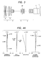
- FIG. 3 is a cross sectional view of a lens system of Numerical Embodiment 2 at the wide angle end in infinity focus.
- FIG. 4A is an aberration diagram of Numerical Embodiment 2 at the wide angle end in focus at an objective distance of 2.5 m.
- FIG. 4B is an aberration diagram of Numerical Embodiment 2 at the intermediate zoom position in focus at an objective distance of 2.5 m.
- FIG. 4C is an aberration diagram of Numerical Embodiment 2 at the telephoto end in focus at an objective distance of 2.5 m.
- FIG. 5 is a cross sectional view of a lens system of Numerical Embodiment 3 at the wide angle end in infinity focus.
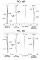
- FIG. 6A is an aberration diagram of Numerical Embodiment 3 at the wide angle end in focus at an objective distance of 2.5 m.
- FIG. 6B is an aberration diagram of Numerical Embodiment 3 at the intermediate zoom position in focus at an objective distance of 2.5 m.
- FIG. 6C is an aberration diagram of Numerical Embodiment 3 at the telephoto end in focus at an objective distance of 2.5 m.
- FIG. 7 is a cross sectional view of a lens system of Numerical Embodiment 4 at the wide angle end in infinity focus.
- FIG. 8A is an aberration diagram of Numerical Embodiment 4 at the wide angle end in focus at an objective distance of 2.8 m.
- FIG. 8B is an aberration diagram of Numerical Embodiment 4 at the intermediate zoom position in focus at an objective distance of 2.8 m.
- FIG. 8C is an aberration diagram of Numerical Embodiment 4 at the telephoto end in focus at an objective distance of 2.8 m.
- FIG. 9 is a schematic diagram illustrating an achromatic positive lens unit and remaining secondary spectrum.
- FIG. 10 is a schematic graph of a distribution of an Abbe number ⁇ and a partial dispersion ratio ⁇ of optical materials.
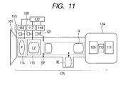
- FIG. 11 is a schematic diagram of a main part of an image pickup apparatus according to the present invention.
- An object of the present invention is to provide a zoom lens system that may correct the secondary spectrum of the longitudinal chromatic aberration appropriately on the telephoto side, and may easily realize high zoom ratio, a small size and light weight, and an image pickup apparatus including the zoom lens system.
- a zoom lens system includes a first lens unit having a positive refractive power which does not move for zooming, a second lens unit having a negative refractive power for magnification action, and a rear lens group including two or more lens units, arranged in this order from an object side to an image side.
- the lens unit does not move for zooming means that the lens unit is not driven for a purpose of zooming, but the lens unit may move for focusing if zooming and focusing are performed simultaneously.
- FIG. 1 is a cross sectional view of a zoom lens system of Embodiment 1 (Numerical Embodiment 1) of the present invention at the wide angle end (short focal length end) in the focus state at the infinite objective distance.
- FIG. 1 is a cross sectional view of a zoom lens system of Embodiment 1 (Numerical Embodiment 1) of the present invention at the wide angle end (short focal length end) in the focus state at the infinite objective distance.
- FIGS. 2A , 2B and 2C are aberration diagram
- FIG 3 is a cross sectional view of a zoom lens system of Embodiment 2 (Numerical Embodiment 2) of the present invention at the wide angle end in the focus state at the infinite objective distance.
- FIG. 5 is a cross sectional view of a zoom lens system of Embodiment 3 (Numerical Embodiment 3) of the present invention at the wide angle end in the focus state at the infinite objective distance.
- FIG. 7 is a cross sectional view of a zoom lens system of Embodiment 4 (Numerical Embodiment 4) of the present invention at the wide angle end in the focus state at the infinite objective distance.
- FIGS. 4 Numerical Embodiment 4
- a front lens unit (first lens unit) F having a positive refractive power does not move for zooming.
- a sub-unit (first sub lens unit) 1a is fixed during focusing (does not move for focusing) and is disposed closest to the object side in the first lens unit F.
- a sub-unit (second sub lens unit) 1b having a positive refractive power moves during focusing and is disposed on the image side in the first lens unit F.
- a variator (second lens unit) V having a negative refractive power for magnification is moved monotonously on the optical axis toward the image plane side, so that magnification (zooming) is performed from the wide angle end to the telephoto end.
- a compensator (third lens unit) C having a negative refractive power moves on the optical axis non-linearly in association with a movement of the second lens unit so as to correct an image plane variation accompanying the magnification.
- the variator V and the compensator C constitute a magnification-varying system.
- a stop (aperture stop) SP is disposed on the image side of the third lens unit C.
- a relay lens unit (fourth lens unit) R having a positive refractive power is fixed so as to have an image formation action.
- a glass block P in the diagrams includes a color separation prism, an optical filter, and the like.
- An image pickup surface I corresponds to an image pickup surface of a solid state image pickup element (photoelectric transducer). Note that the compensator C and the relay lens unit R constitute a rear lens group.
- a front lens unit (first lens unit) F having a positive refractive power does not move for zooming.
- a sub-unit (first sub lens unit) 1a does not move for focusing and is disposed closest to the object side in the first lens unit F.
- a sub-unit (second sub lens unit) 1b having a positive refractive power moves during focusing and is disposed on the image side in the first lens unit F.
- a first variator (second lens unit) V1 having a negative refractive power for magnification is moved on the optical axis toward the image plane side, so that magnification (zooming) is performed from the wide angle end to the telephoto end.
- a second variator (third lens unit) V2 having a negative refractive power works for magnification in the same manner as the first variator V1.
- a fixed lens unit (fourth lens unit) R having a positive refractive power is fixed.
- a compensator (fifth lens unit) C having a positive refractive power moves on the optical axis non-linearly so as to correct an image plane variation accompanying the magnification.
- the first variator V1, the second variator V2, and the compensator C constitute the magnification system.
- a stop (aperture stop) SP is disposed on the image side of the second variator V2.
- a glass block P in the diagram includes a color separation prism, an optical filter, and the like.
- An image pickup surface I corresponds to an image pickup surface of a solid state image pickup element. Note that the second variator V2, the fixed lens unit R, and the compensator C constitute a rear lens group.
- the first lens unit F includes the first sub lens unit 1a which does not move for focusing and the second sub lens unit 1b which moves for focusing.
- the first sub lens unit 1a includes two or more negative lenses and one or more positive lenses.
- An average Abbe number of materials of the negative lenses included in the first sub lens unit 1a and an average partial dispersion ratio are denoted by ⁇ na and ⁇ na, respectively.
- An average Abbe number of materials of the positive lenses included in the first lens unit F and an average partial dispersion ratio are denoted by ⁇ pa and ⁇ pa, respectively.
- a combined focal length of the negative lenses included in the first sub lens unit 1a is denoted by f1ns, and a focal length of the zoom lens system at the telephoto end is denoted by ft. Then, the following conditions are satisfied. - 1.193 ⁇ 10 - 3 ⁇ ⁇ pa - ⁇ na / ⁇ pa - ⁇ na ⁇ - 0.904 ⁇ 10 - 3 40 ⁇ ⁇ pa - ⁇ na ⁇ 55 - 0.465 ⁇ f ⁇ 1 ⁇ ns / ft
- the conditions including the lens configuration of the first lens unit F and the dispersion characteristic of the lens material are defined by the conditional expressions (1) to (3), so that the secondary spectrum of the longitudinal chromatic aberration at the telephoto end is corrected appropriately.
- the conditional expression (1) shows the condition for reducing a remaining amount of the secondary spectrum of the longitudinal chromatic aberration in the first lens unit F so that the secondary spectrum of the longitudinal chromatic aberration at the telephoto end is appropriately corrected. The general outline of this condition is described with reference to FIGS. 9 and 10 .
- FIG. 9 is a schematic diagram illustrating an achromatic lens unit LP having a positive refractive power and remaining secondary spectrum.
- FIG. 10 is a schematic diagram of a distribution of an Abbe number ⁇ and a partial dispersion ratio ⁇ of existing optical materials.
- the existing optical material is distributed in the region having narrow partial dispersion ratio ⁇ with respect to the Abbe number ⁇ , and there is a tendency that the partial dispersion ratio ⁇ increases as the Abbe number ⁇ decreases.
- an imaging position is identical between the C-line and the F-line as illustrated in FIG. 9 .
- the positive lens G1 has a small partial dispersion ratio ⁇ 1
- the negative lens G2 has a large partial dispersion ratio ⁇ 2 as illustrated in FIG. 10 .
- ⁇ - 1 / ⁇ ⁇ ⁇ ⁇ 1 - ⁇ ⁇ 2 / ⁇ ⁇ 1 - ⁇ ⁇ 2
- the secondary spectrum amounts of the first sub lens unit 1a, the second sub lens unit 1b, and the lens unit in the image side of the magnification systems V and C are denoted by ⁇ 1a, ⁇ 1b, and ⁇ Z, respectively.
- Imaging magnification factors of the second sub lens unit 1b and the lens unit in the image side of the magnification systems V and C are denoted by ⁇ 1b and ⁇ Z, respectively.
- the secondary spectrum amount ⁇ of the entire lens system is expressed by the following equation.
- ⁇ ⁇ ⁇ 1 ⁇ a ⁇ ⁇ ⁇ 1 ⁇ b 2 ⁇ ⁇ Z 2 + ⁇ ⁇ 1 ⁇ b ⁇ 1 - ⁇ ⁇ 1 ⁇ b ⁇ ⁇ Z 2 + ⁇ Z ⁇ 1 - ⁇ Z
- the secondary spectrum amount ⁇ becomes significant in the first sub lens unit 1a and the second sub lens unit 1b in which an axial marginal light beam passes through at a high position on the telephoto side. Therefore, the longitudinal chromatic aberration secondary spectrum amount ⁇ may be reduced on the telephoto side by suppressing the sum of the secondary spectrum amounts ⁇ 1a and ⁇ 1b of the longitudinal chromatic aberration generated in the first sub lens unit 1a and the second sub lens unit 1b.
- the conditional expression (2) defines a relative relationship between material dispersions of the positive lens and the negative lens for the first lens unit F to have an appropriate achromatic effect. If the upper limit of the conditional expression (2) is exceeded, it becomes difficult for the first lens unit F including the positive lens and the negative lens for the achromatic effect to have an appropriate refractive power. Then, it becomes difficult to push the rear principal point position of the first lens unit F toward the image side. As a result, it becomes difficult to realize wide angle and to reduce size and weight of the first lens unit F. If the lower limit of the conditional expression (2) is exceeded, each lens power in the first lens unit F increases so that a curvature of the lens surface increases. As a result, it becomes difficult to correct, in particular, higher order aberration. In addition, the lens becomes thick, so that it becomes difficult to reduce size and weight of the first lens unit F.
- the conditional expression (3) defines the condition to satisfy both appropriate correction of the chromatic aberration and reduction of size and weight of the first lens unit F when a zoom lens system having a large magnification ratio (zoom ratio) is obtained. If the lower limit of the conditional expression (3) is exceeded, the negative refractive power included in the first sub lens unit 1a is decreased, so that it becomes difficult to obtain the appropriate achromatic effect at the telephoto end of the zoom lens. In addition, it becomes difficult to push the rear principal point position of the first lens unit F toward the image side, and it becomes difficult to realize a wide angle and to reduce size and weight of the first lens unit F. Further, it is preferred that numerical value ranges of the conditional expressions (1) to (3) be set as follows.
- conditional expressions (1a) and (2a) are the same as the technical meanings of the conditional expressions (1) and (2) described above. If the upper limit of the conditional expression (3a) is exceeded, the negative refractive power included in the first sub lens unit 1a increases, so that it becomes difficult to correct various aberrations, in particular, the higher order aberration. In addition, a curvature of the lens surface of the negative lens increases, so that it becomes difficult to reduce size and weight of the first lens unit F.
- a zoom lens system having a high zoom ratio in which the secondary spectrum of the longitudinal chromatic aberration is appropriately corrected at the telephoto end, and in which reduction of size and weight is achieved.
- f1 represents a focal length of the first lens unit F
- fw represents a focal length of the zoom lens system at the wide angle end.
- conditional expression (4) defines the average Abbe number ⁇ na of materials of negative lenses included in the first sub lens unit 1a that are appropriate for correcting the secondary spectrum of the longitudinal chromatic aberration of the zoom lens system at the telephoto side more appropriately.
- the refracting powers of the two negative lenses in the first sub lens unit 1a increase, so that it becomes difficult to correct various aberrations, in particular, higher order aberration.
- a curvature of the lens surface of the lens increases, so that the lens becomes thick.
- the two negative lenses in the first lens unit F may not have appropriate refracting powers, so that it becomes difficult to push a principal point interval toward the image side. As a result, it becomes difficult to realize a wide angle and to reduce size and weight of the first lens unit F.
- the conditional expression (5) defines an optimal range of the focal length of the first lens unit F with respect to the focal length at the telephoto end for realizing high magnification-varying factor (high zoom ratio) while the longitudinal chromatic aberration is corrected appropriately. If the lower limit of the conditional expression (5) is exceeded, the refractive power of the first lens unit F increases, so that it becomes difficult to correct mainly spherical aberration at the telephoto end and higher order components of the off-axial aberration appropriately. If the upper limit of the conditional expression (5) is exceeded, the refracting power of the first lens unit F is decreased, so that it becomes difficult to realize both the high zooming factor (high zoom ratio) and downsizing of the first lens unit F.
- the conditional expression (6) is for correcting the chromatic aberration appropriately at the telephoto end while obtaining an optimal zoom ratio. If the zoom ratio exceeds the lower limit of the conditional expression (6), it is easy to realize reduction of size and weight without deteriorating the longitudinal chromatic aberration at the telephoto end and various aberrations even by the conventional lens structure. It is more preferred that the numerical value ranges in the conditional expressions (4) to (6) be set as follows. 20.0 ⁇ ⁇ na ⁇ 30.0 0.360 ⁇ f ⁇ 1 / ft ⁇ 0.423 16 ⁇ ft / fw ⁇ 25
- the zoom lens system of the present invention is used for an image pickup apparatus including a photoelectric transducer such as a CCD, it is preferred that the condition expressed by the following expression be satisfied, 0.6 ⁇ fw / IS where IS represents a diagonal length of an effective surface of the photoelectric transducer.
- the conditional expression (7) defines an optimal relative relationship between the focal length at the wide angle end of a zoom lens system and the diagonal length of the image pickup element when the zoom lens system of the present invention is used for the image pickup apparatus. If the lower limit of the conditional expression (7) is exceeded, the zoom lens system becomes to have an excessively wide field angle, so that it becomes difficult to correct a distortion or off-axial aberration such as lateral chromatic aberration. It is more preferred that the numerical value of the conditional expression (7) be set as follows. 0.62 ⁇ fw / IS ⁇ 0.80
- the first lens unit F corresponds to the first to the twelfth lens surfaces, and is constituted by the first sub lens unit 1a including the first to the sixth lens surfaces and the second sub lens unit 1b including the seventh to the twelfth surfaces.
- the first sub lens unit 1a is constituted by a negative lens, a negative lens, and a positive lens arranged in this order from the object side.
- the second sub lens unit 1b is constituted by three positive lenses.
- Table 1 shows values corresponding to the individual conditional expressions in Embodiment 1. Numerical Embodiment 1 satisfies every conditional expression, so that the longitudinal chromatic aberration is appropriately corrected at the telephoto end while the high zoom ratio (high magnification factor) and reduction in size and weight of the entire system are achieved.
- the first lens unit F corresponds to the first to the fourteenth lens surfaces, and is constituted by the first sub lens unit 1a including the first to the eighth lens surfaces and the second sub lens unit 1b including the ninth to the fourteenth surfaces.
- the first sub lens unit 1a is constituted by a negative lens, a positive lens, a negative lens, and a positive lens arranged in this order from the object side.
- the second sub lens unit 1b is constituted by three positive lenses.
- Table 1 shows values corresponding to the individual conditional expressions in Embodiment 2. Numerical Embodiment 2 satisfies every conditional expression, so that the longitudinal chromatic aberration is appropriately corrected at the telephoto end while the high zoom ratio and reduction in size and weight of the entire system are achieved.
- the first lens unit F corresponds to the first to the fourteenth lens surfaces, and is constituted by the first sub lens unit 1a including the first to the eighth lens surfaces and the second sub lens unit 1b including the ninth to the fourteenth surfaces.
- the first sub lens unit 1a is constituted by a negative lens, a positive lens, a negative lens, and a positive lens arranged in this order from the object side.
- the second sub lens unit 1b is constituted by three positive lenses.
- Table 1 shows values corresponding to the individual conditional expressions in Embodiment 3. Numerical Embodiment 3 satisfies every conditional expression, so that the longitudinal chromatic aberration is appropriately corrected at the telephoto end while the high zoom ratio and reduction in size and weight of the entire system are achieved.
- the first lens unit F in Embodiment 4 illustrated in FIG. 7 is described.
- the first lens unit F corresponding to the first to the eleventh lens surfaces and is constituted by the first sub lens unit 1a including the first to the seventh lens surfaces and the second sub lens unit 1b including the eighth to the eleventh surfaces.
- the first sub lens unit 1a is constituted by a negative lens, a cemented lens constituted by a negative lens and a positive lens, and a positive lens arranged in this order from the object side.
- the second sub lens unit 1b is constituted by two positive lenses. Table 1 shows values corresponding to the individual conditional expressions in Embodiment 4.
- Numerical Embodiment 4 satisfies every conditional expression, so that the longitudinal chromatic aberration is appropriately corrected at the telephoto end while the high zoom ratio and the reduction in size and weight are achieved.
- the preferred embodiments of the present invention are described. However, it goes without saying that the present invention is not limited to these embodiments, which may be modified and changed variously within the spirit thereof.
- FIG. 11 is a principal schematic diagram illustrating an image pickup apparatus (television (TV) camera system) using the zoom lens system according to each of the Embodiments 1 to 3 as an image pickup optical system.
- a zoom lens system 101 according to any one of Embodiments 1 to 3 and a camera 124 are provided.
- the zoom lens system 101 is detachably attached to the camera 124.
- An image pickup apparatus 125 has a structure in which the zoom lens system 101 is attached to the camera 124.
- the zoom lens system 101 includes a first lens unit F, a magnification-varying section LZ, and a fourth lens unit R for imaging.
- the first lens unit F includes a focusing lens unit.
- the magnification section LZ includes a second lens unit which moves on the optical axis so as to vary the magnification and a third lens unit which moves on the optical axis so as to correct an image plane variation accompanying the magnification.
- the zoom lens system 101 includes the aperture stop SP.
- the fourth lens unit R includes a lens unit (magnification optical system) IE which may be inserted onto or removed from the optical path.
- the lens unit IE is provided to shift the focal length range of the entire system of the zoom lens system 101.
- Drive mechanisms 114 and 115 such as helicoids or cams drive the first lens unit F and the magnification section LZ, respectively, in the optical axis direction.
- Motors (drive units) 116 to 118 are provided to electrically drive the drive mechanisms 114 and 115 and the aperture stop SP.
- Detectors 119 to 121 such as encoders, potentiometers, or photosensors detect positions of the first lens unit F and the magnification section LZ on the optical axis and a stop diameter of the aperture stop SP.
- the camera 124 includes a glass block 109 corresponding to an optical filter or a color separation prism, and a solid-state image pickup element (photoelectric transducer) 110 such as a CCD sensor or a CMOS sensor, for receiving a subject image formed by the zoom lens system 101.
- CPUs 111 and 122 perform various drive controls of the camera 124 and the main body of the zoom lens system 101, respectively.
- the zoom lens system according to the present invention is applied to the TV camera system as described above, the image pickup apparatus having high optical performance is realized.
- the zoom lens system according to the Embodiment 4 of the present invention may also be applied to a TV camera as in the case of Embodiments 1 to 3.
- a surface number "i" is counted from the object side.
- ri indicates a curvature radius of an i-th surface counted from the object side
- di indicates an interval between the i-th surface and an (i+1)-th surface which are counted from the image side.
- ndi and ⁇ di indicate a refractive power and an Abbe number of an i-th optical material, respectively.
- Last three surfaces correspond to a glass block such as a filter.
- the optical axis direction is an X-axis
- a direction perpendicular to the optical axis is an H axis
- a light traveling direction is positive.
- R denotes a paraxial curvature radius
- k denotes a conic constant
- A3, A4, A5, A6, A7, A8, A9, A10, A11, and A12 denote aspherical coefficients
- an aspherical surface shape is expressed by the following expression.
- "e-Z" indicates “ ⁇ 10 -2 ".
- the mark "*" indicates the aspherical surface.
- Table 1 shows a correspondence relationship between the respective embodiments and the conditional expressions described above.
- a zoom lens including in order from an object side to an image side: a positive first lens unit which does not move for zooming; a negative second lens unit for magnification, and a rear lens group including two or more lens units, in which: the first lens unit includes a first subunit not moving for focusing and a second subunit moving for focusing, and the first subunit includes two or more negative lenses and one or more positive lenses; and an average Abbe number and an average partial dispersion ratio of materials of the negative lenses included in the first subunit, average Abbe number and average partial dispersion ratio of materials of the one or more positive lenses included in the first lens unit, combined focal length of the negative lenses included in the first subunit, and focal length of the zoom lens at telephoto end are appropriately set.
Landscapes
- Physics & Mathematics (AREA)
- General Physics & Mathematics (AREA)
- Optics & Photonics (AREA)
- Nonlinear Science (AREA)
- Chemical & Material Sciences (AREA)
- Dispersion Chemistry (AREA)
- Lenses (AREA)
Abstract
Description
- The present invention relates to a zoom lens system which is suitable for use in a broadcasting television (TV) camera, a video camera, a digital still camera, and a silver-halide camera, and also to an image pickup apparatus including the zoom lens.
- In recent years, there have been demanded a zoom lens system having a high zoom ratio and high optical performance for image pickup apparatus such as a television (TV) camera, a silver-halide camera, a digital camera, and a video camera. A positive lead and telephoto type four-unit zoom lens system in which four lens units are provided in total and one of the lens units located closest to an object side has a positive refractive power has been known as the zoom lens system having a high zoom ratio. For instance, there is known a four-unit zoom lens system which includes a first lens unit having a positive refractive power for focusing, a second lens unit having a negative refractive power for magnification, a third lens unit having a negative refractive power for correcting image plane variation, and a fourth lens unit having a positive refractive power for image formation. As to this four-unit zoom lens system, there is known a four-unit zoom lens system in which an optical material having an extraordinary dispersion characteristic is used, so that chromatic aberration is corrected appropriately and a high optical performance is provided (see
U.S. Patent Nos. 6,825,990 and6,141,157 ). -
U.S. Patent No. 6,825,990 discloses a structure in which a first sub lens unit which is fixed during focusing in a first lens unit which is fixed during zooming includes two negative lenses. As to the two negative lenses, a low dispersion material is used as a material of the negative lens disposed on the side closest to an object, so that lateral chromatic aberration is corrected appropriately mainly at the wide angle end.US Patent No. 6,141,157 discloses a structure in which a thin resin layer having a meniscus shape and a negative refractive power is formed on a lens surface of a second or third positive lens counted from the object side in a first lens unit which is fixed during zooming. Utilizing this resin layer, higher order lateral chromatic aberration is corrected appropriately mainly on the wide angle side without an increase in size or weight. - A positive lead type four-unit zoom lens system having a structure described above may support a high zoom ratio relatively easily. In order to obtain high optical performance in this four-unit zoom lens system, it is important to correct lateral chromatic aberration at the wide angle end and longitudinal chromatic aberration at the telephoto end appropriately. It is easy to correct the chromatic aberration appropriately including the lateral chromatic aberration and the longitudinal chromatic aberration if an optical material having an extraordinary dispersion characteristic is used. However, it is difficult to correct the chromatic aberration appropriately by simply using a lens made of the optical material having an extraordinary dispersion characteristic. In particular, in order to obtain high optical performance over the entire zoom range in the four-unit zoom lens system described above, it is an important factor to set appropriately a material of each lens included in the first lens unit which does not move for zooming. For instance, in order to correct a secondary spectrum of the longitudinal chromatic aberration appropriately on the telephoto side, it is important to set an appropriate difference between dispersions of materials of the positive lens and the negative lens in the first lens unit. If this difference is set inappropriately, it is difficult to suppress higher order aberration mainly.
- A zoom lens system according to the present invention includes in order of from an object side to an image side: a first lens unit (F) having a positive refractive power, which does not move for zooming; a second lens unit (V, V1) having a negative refractive power for a magnification action; and a rear lens group including two or more lens units, characterized in that: the first lens unit (F) includes a first sub lens unit (1a) which does not move for focusing and a second sub lens unit (1b) which moves for focusing, and the first sub lens unit includes two or more negative lenses and one or more positive lenses; and the following conditional expressions are relative,
-1.193×10⁻³<(θpa-θna)/(νpa-νma)<-0. 904×10-3;
40<νpa-νna<55; and
-0.465<f1ns/ft,
where νna and θna represent an average Abbe number and an average partial dispersion ratio of materials of the two or more negative lenses included in the first sub lens unit (1a), respectively, νpa and θpa represent an average Abbe number and an average partial dispersion ratio of materials of the one or more positive lenses included in the first lens unit (F), respectively, f1ns represents a combined focal length of the two or more negative lenses included in the first sub lens unit (1a), and ft represents a focal length of the zoom lens system at a telephoto end. - Further features of the present invention will become apparent from the following description of exemplary embodiments with reference to the attached drawings.
-
FIG. 1 is a cross sectional view of a lens system of Numerical Embodiment 1 at the wide angle end in infinity focus. -
FIG. 2A is an aberration diagram of Numerical Embodiment 1 at the wide angle end in focus at an objective distance of 2.5 m. -
FIG. 2B is an aberration diagram of Numerical Embodiment 1 at the intermediate zoom position in focus at an objective distance of 2.5 m. -
FIG. 2C is an aberration diagram of Numerical Embodiment 1 at the telephoto end in focus at an objective distance of 2.5 m. -
FIG. 3 is a cross sectional view of a lens system of Numerical Embodiment 2 at the wide angle end in infinity focus. -
FIG. 4A is an aberration diagram of Numerical Embodiment 2 at the wide angle end in focus at an objective distance of 2.5 m. -
FIG. 4B is an aberration diagram of Numerical Embodiment 2 at the intermediate zoom position in focus at an objective distance of 2.5 m. -
FIG. 4C is an aberration diagram of Numerical Embodiment 2 at the telephoto end in focus at an objective distance of 2.5 m. -
FIG. 5 is a cross sectional view of a lens system of Numerical Embodiment 3 at the wide angle end in infinity focus. -
FIG. 6A is an aberration diagram of Numerical Embodiment 3 at the wide angle end in focus at an objective distance of 2.5 m. -
FIG. 6B is an aberration diagram of Numerical Embodiment 3 at the intermediate zoom position in focus at an objective distance of 2.5 m. -
FIG. 6C is an aberration diagram of Numerical Embodiment 3 at the telephoto end in focus at an objective distance of 2.5 m. -
FIG. 7 is a cross sectional view of a lens system of Numerical Embodiment 4 at the wide angle end in infinity focus. -
FIG. 8A is an aberration diagram of Numerical Embodiment 4 at the wide angle end in focus at an objective distance of 2.8 m. -
FIG. 8B is an aberration diagram of Numerical Embodiment 4 at the intermediate zoom position in focus at an objective distance of 2.8 m. -
FIG. 8C is an aberration diagram of Numerical Embodiment 4 at the telephoto end in focus at an objective distance of 2.8 m. -
FIG. 9 is a schematic diagram illustrating an achromatic positive lens unit and remaining secondary spectrum. -
FIG. 10 is a schematic graph of a distribution of an Abbe number ν and a partial dispersion ratio θ of optical materials. -
FIG. 11 is a schematic diagram of a main part of an image pickup apparatus according to the present invention. - An object of the present invention is to provide a zoom lens system that may correct the secondary spectrum of the longitudinal chromatic aberration appropriately on the telephoto side, and may easily realize high zoom ratio, a small size and light weight, and an image pickup apparatus including the zoom lens system.
- Hereinafter, an embodiment of the present invention is described in detail with reference to the attached drawings. A zoom lens system according to the present invention includes a first lens unit having a positive refractive power which does not move for zooming, a second lens unit having a negative refractive power for magnification action, and a rear lens group including two or more lens units, arranged in this order from an object side to an image side. Here, "the lens unit does not move for zooming" means that the lens unit is not driven for a purpose of zooming, but the lens unit may move for focusing if zooming and focusing are performed simultaneously.
-
FIG. 1 is a cross sectional view of a zoom lens system of Embodiment 1 (Numerical Embodiment 1) of the present invention at the wide angle end (short focal length end) in the focus state at the infinite objective distance.FIGS. 2A ,2B and 2C are aberration diagrams of Numerical Embodiment 1 in focus at an objective distance of 2.5 m at the wide angle end, at the intermediate zoom position (focal length f=33.3 mm), and at the telephoto end (long focal length end), respectively. Note that the focal length and the objective distance are values when the values of Numerical Embodiments are expressed in the unit of mm. The same is true for each of the following embodiments.FIG. 3 is a cross sectional view of a zoom lens system of Embodiment 2 (Numerical Embodiment 2) of the present invention at the wide angle end in the focus state at the infinite objective distance.FIGS. 4A ,4B and 4C are aberration diagrams of Numerical Embodiment 2 in focus at an objective distance of 2.5 m at the wide angle end, at the intermediate zoom position (focal length f=33.3 mm), and at the telephoto end, respectively. -
FIG. 5 is a cross sectional view of a zoom lens system of Embodiment 3 (Numerical Embodiment 3) of the present invention at the wide angle end in the focus state at the infinite objective distance.FIGS. 6A ,6B and 6C are aberration diagrams of Numerical Embodiment 3 in focus at an objective distance of 2.5 m at the wide angle end, at the intermediate zoom position (focal length f=35 mm), and at the telephoto end, respectively.FIG. 7 is a cross sectional view of a zoom lens system of Embodiment 4 (Numerical Embodiment 4) of the present invention at the wide angle end in the focus state at the infinite objective distance.FIGS. 8A ,8B and 8C are aberration diagrams of Numerical Embodiment 4 in focus at an objective distance of 2.8 m at the wide angle end, at the intermediate zoom position (focal length f=29.5 mm), and at the telephoto end, respectively. - In the cross sectional views in
FIGS. 1 ,3 and5 , a front lens unit (first lens unit) F having a positive refractive power does not move for zooming. A sub-unit (first sub lens unit) 1a is fixed during focusing (does not move for focusing) and is disposed closest to the object side in the first lens unit F. A sub-unit (second sub lens unit) 1b having a positive refractive power moves during focusing and is disposed on the image side in the first lens unit F. A variator (second lens unit) V having a negative refractive power for magnification is moved monotonously on the optical axis toward the image plane side, so that magnification (zooming) is performed from the wide angle end to the telephoto end. A compensator (third lens unit) C having a negative refractive power moves on the optical axis non-linearly in association with a movement of the second lens unit so as to correct an image plane variation accompanying the magnification. The variator V and the compensator C constitute a magnification-varying system. A stop (aperture stop) SP is disposed on the image side of the third lens unit C. A relay lens unit (fourth lens unit) R having a positive refractive power is fixed so as to have an image formation action. A glass block P in the diagrams includes a color separation prism, an optical filter, and the like. An image pickup surface I corresponds to an image pickup surface of a solid state image pickup element (photoelectric transducer). Note that the compensator C and the relay lens unit R constitute a rear lens group. - In
FIG. 7 , a front lens unit (first lens unit) F having a positive refractive power does not move for zooming. A sub-unit (first sub lens unit) 1a does not move for focusing and is disposed closest to the object side in the first lens unit F. A sub-unit (second sub lens unit) 1b having a positive refractive power moves during focusing and is disposed on the image side in the first lens unit F. A first variator (second lens unit) V1 having a negative refractive power for magnification is moved on the optical axis toward the image plane side, so that magnification (zooming) is performed from the wide angle end to the telephoto end. A second variator (third lens unit) V2 having a negative refractive power works for magnification in the same manner as the first variator V1. A fixed lens unit (fourth lens unit) R having a positive refractive power is fixed. A compensator (fifth lens unit) C having a positive refractive power moves on the optical axis non-linearly so as to correct an image plane variation accompanying the magnification. The first variator V1, the second variator V2, and the compensator C constitute the magnification system. A stop (aperture stop) SP is disposed on the image side of the second variator V2. A glass block P in the diagram includes a color separation prism, an optical filter, and the like. An image pickup surface I corresponds to an image pickup surface of a solid state image pickup element. Note that the second variator V2, the fixed lens unit R, and the compensator C constitute a rear lens group. - In each embodiment, the first lens unit F includes the first
sub lens unit 1a which does not move for focusing and the secondsub lens unit 1b which moves for focusing. The firstsub lens unit 1a includes two or more negative lenses and one or more positive lenses. An average Abbe number of materials of the negative lenses included in the firstsub lens unit 1a and an average partial dispersion ratio are denoted by νna and θna, respectively. An average Abbe number of materials of the positive lenses included in the first lens unit F and an average partial dispersion ratio are denoted by νpa and θpa, respectively. A combined focal length of the negative lenses included in the firstsub lens unit 1a is denoted by f1ns, and a focal length of the zoom lens system at the telephoto end is denoted by ft. Then, the following conditions are satisfied.


- Here, the combined focal length f1ns is expressed by the following equation:

where n represents a number of negative lenses included and fi represents a focal length of the i-th negative lens. - In each embodiment, the conditions including the lens configuration of the first lens unit F and the dispersion characteristic of the lens material are defined by the conditional expressions (1) to (3), so that the secondary spectrum of the longitudinal chromatic aberration at the telephoto end is corrected appropriately. The conditional expression (1) shows the condition for reducing a remaining amount of the secondary spectrum of the longitudinal chromatic aberration in the first lens unit F so that the secondary spectrum of the longitudinal chromatic aberration at the telephoto end is appropriately corrected. The general outline of this condition is described with reference to
FIGS. 9 and 10 . -
FIG. 9 is a schematic diagram illustrating an achromatic lens unit LP having a positive refractive power and remaining secondary spectrum.FIG. 10 is a schematic diagram of a distribution of an Abbe number ν and a partial dispersion ratio θ of existing optical materials. Here, the Abbe number ν and the partial dispersion ratio θ are respectively expressed by the following equations:

where Ng represents a refractive index with respect to the g-line, NF represents a refractive index with respect to the F-line, Nd represents a refractive index with respect to the d-line, and NC represents a refractive index with respect to the C-line. - As illustrated in
FIG. 10 , the existing optical material is distributed in the region having narrow partial dispersion ratio θ with respect to the Abbe number ν, and there is a tendency that the partial dispersion ratio θ increases as the Abbe number ν decreases. A correction condition of chromatic aberration of a thin lens system constituted of two lenses G1 and G2 having refracting powers ϕ1 and ϕ2 and Abbe numbers of materials ν1 and ν2, respectively is expressed by the following equation.
- Here, combined refracting power ϕ is expressed as follows.

- If the equation (c) is satisfied, an imaging position is identical between the C-line and the F-line as illustrated in
FIG. 9 . - In this case, the refracting powers ϕ1 and ϕ2 are expressed by the following equations.


- In
FIG. 9 , as to the achromatic lens unit LP having a positive refractive power, a material having a large Abbe number ν1 is used for the positive lens G1, and a material having a small Abbe number ν2 is used for the negative lens G2. Therefore, the positive lens G1 has a small partial dispersion ratio θ1, and the negative lens G2 has a large partial dispersion ratio θ2 as illustrated inFIG. 10 . As illustrated inFIG. 9 , if the chromatic aberration is corrected at the F-line and the C-line, the imaging point at the g-line is shifted to the image side. This deviation amount defined as a secondary spectrum amount Δ is expressed by the following equation.
- Here, the secondary spectrum amounts of the first
sub lens unit 1a, the secondsub lens unit 1b, and the lens unit in the image side of the magnification systems V and C are denoted by Δ1a, Δ1b, and ΔZ, respectively. Imaging magnification factors of the secondsub lens unit 1b and the lens unit in the image side of the magnification systems V and C are denoted by β1b and βZ, respectively. Then, the secondary spectrum amount Δ of the entire lens system is expressed by the following equation.
- The secondary spectrum amount Δ becomes significant in the first
sub lens unit 1a and the secondsub lens unit 1b in which an axial marginal light beam passes through at a high position on the telephoto side. Therefore, the longitudinal chromatic aberration secondary spectrum amount Δ may be reduced on the telephoto side by suppressing the sum of the secondary spectrum amounts Δ1a and Δ1b of the longitudinal chromatic aberration generated in the firstsub lens unit 1a and the secondsub lens unit 1b. - When the upper limit of the conditional expression (1) is exceeded, dispersions of the positive lens and the negative lens naturally become close to each other in existing general optical materials. Then, each lens power in the first lens unit F increases so that a curvature of the lens surface increases. As a result, it becomes difficult to correct various aberrations, in particular, a higher order aberration. In addition, because the lens becomes thick, it becomes difficult to reduce size and weight of the first lens unit F. If the lower limit of the conditional expression (1) is exceeded, the sum of the secondary spectrum amounts (Δ1a+Δ1b) of the first
sub lens unit 1a and the secondsub lens unit 1b increases. Therefore, it becomes difficult to correct the longitudinal chromatic aberration appropriately on the telephoto end. - The conditional expression (2) defines a relative relationship between material dispersions of the positive lens and the negative lens for the first lens unit F to have an appropriate achromatic effect. If the upper limit of the conditional expression (2) is exceeded, it becomes difficult for the first lens unit F including the positive lens and the negative lens for the achromatic effect to have an appropriate refractive power. Then, it becomes difficult to push the rear principal point position of the first lens unit F toward the image side. As a result, it becomes difficult to realize wide angle and to reduce size and weight of the first lens unit F. If the lower limit of the conditional expression (2) is exceeded, each lens power in the first lens unit F increases so that a curvature of the lens surface increases. As a result, it becomes difficult to correct, in particular, higher order aberration. In addition, the lens becomes thick, so that it becomes difficult to reduce size and weight of the first lens unit F.
- The conditional expression (3) defines the condition to satisfy both appropriate correction of the chromatic aberration and reduction of size and weight of the first lens unit F when a zoom lens system having a large magnification ratio (zoom ratio) is obtained. If the lower limit of the conditional expression (3) is exceeded, the negative refractive power included in the first
sub lens unit 1a is decreased, so that it becomes difficult to obtain the appropriate achromatic effect at the telephoto end of the zoom lens. In addition, it becomes difficult to push the rear principal point position of the first lens unit F toward the image side, and it becomes difficult to realize a wide angle and to reduce size and weight of the first lens unit F. Further, it is preferred that numerical value ranges of the conditional expressions (1) to (3) be set as follows.


- The technical meanings of the conditional expressions (1a) and (2a) are the same as the technical meanings of the conditional expressions (1) and (2) described above. If the upper limit of the conditional expression (3a) is exceeded, the negative refractive power included in the first
sub lens unit 1a increases, so that it becomes difficult to correct various aberrations, in particular, the higher order aberration. In addition, a curvature of the lens surface of the negative lens increases, so that it becomes difficult to reduce size and weight of the first lens unit F. - With the structure described above, it is possible to provide a zoom lens system having a high zoom ratio in which the secondary spectrum of the longitudinal chromatic aberration is appropriately corrected at the telephoto end, and in which reduction of size and weight is achieved. In each embodiment, it is more preferred that one or more of the following conditions be satisfied,


where f1 represents a focal length of the first lens unit F, fw represents a focal length of the zoom lens system at the wide angle end. - The conditional expression (4) defines the average Abbe number νna of materials of negative lenses included in the first
sub lens unit 1a that are appropriate for correcting the secondary spectrum of the longitudinal chromatic aberration of the zoom lens system at the telephoto side more appropriately. - If the upper limit of the conditional expression (4) is exceeded, the refracting powers of the two negative lenses in the first
sub lens unit 1a increase, so that it becomes difficult to correct various aberrations, in particular, higher order aberration. In addition, a curvature of the lens surface of the lens increases, so that the lens becomes thick. As a result, it becomes difficult to reduce size and weight of the firstsub lens unit 1a. If the lower limit of the conditional expression (4) is exceeded, the two negative lenses in the first lens unit F may not have appropriate refracting powers, so that it becomes difficult to push a principal point interval toward the image side. As a result, it becomes difficult to realize a wide angle and to reduce size and weight of the first lens unit F. - The conditional expression (5) defines an optimal range of the focal length of the first lens unit F with respect to the focal length at the telephoto end for realizing high magnification-varying factor (high zoom ratio) while the longitudinal chromatic aberration is corrected appropriately. If the lower limit of the conditional expression (5) is exceeded, the refractive power of the first lens unit F increases, so that it becomes difficult to correct mainly spherical aberration at the telephoto end and higher order components of the off-axial aberration appropriately. If the upper limit of the conditional expression (5) is exceeded, the refracting power of the first lens unit F is decreased, so that it becomes difficult to realize both the high zooming factor (high zoom ratio) and downsizing of the first lens unit F.
- The conditional expression (6) is for correcting the chromatic aberration appropriately at the telephoto end while obtaining an optimal zoom ratio. If the zoom ratio exceeds the lower limit of the conditional expression (6), it is easy to realize reduction of size and weight without deteriorating the longitudinal chromatic aberration at the telephoto end and various aberrations even by the conventional lens structure. It is more preferred that the numerical value ranges in the conditional expressions (4) to (6) be set as follows.



- When the zoom lens system of the present invention is used for an image pickup apparatus including a photoelectric transducer such as a CCD, it is preferred that the condition expressed by the following expression be satisfied,

where IS represents a diagonal length of an effective surface of the photoelectric transducer. - The conditional expression (7) defines an optimal relative relationship between the focal length at the wide angle end of a zoom lens system and the diagonal length of the image pickup element when the zoom lens system of the present invention is used for the image pickup apparatus. If the lower limit of the conditional expression (7) is exceeded, the zoom lens system becomes to have an excessively wide field angle, so that it becomes difficult to correct a distortion or off-axial aberration such as lateral chromatic aberration. It is more preferred that the numerical value of the conditional expression (7) be set as follows.

- Next, the configuration of the first lens unit F in each embodiment is described. First, the configuration of the first lens unit F in Embodiment 1 illustrated in
FIG. 1 is described. The first lens unit F corresponds to the first to the twelfth lens surfaces, and is constituted by the firstsub lens unit 1a including the first to the sixth lens surfaces and the secondsub lens unit 1b including the seventh to the twelfth surfaces. The firstsub lens unit 1a is constituted by a negative lens, a negative lens, and a positive lens arranged in this order from the object side. The secondsub lens unit 1b is constituted by three positive lenses. Table 1 shows values corresponding to the individual conditional expressions in Embodiment 1. Numerical Embodiment 1 satisfies every conditional expression, so that the longitudinal chromatic aberration is appropriately corrected at the telephoto end while the high zoom ratio (high magnification factor) and reduction in size and weight of the entire system are achieved. - Next, the configuration of the first lens unit F in Embodiment 2 illustrated in
FIG. 3 is described. The first lens unit F corresponds to the first to the fourteenth lens surfaces, and is constituted by the firstsub lens unit 1a including the first to the eighth lens surfaces and the secondsub lens unit 1b including the ninth to the fourteenth surfaces. The firstsub lens unit 1a is constituted by a negative lens, a positive lens, a negative lens, and a positive lens arranged in this order from the object side. The secondsub lens unit 1b is constituted by three positive lenses. Table 1 shows values corresponding to the individual conditional expressions in Embodiment 2. Numerical Embodiment 2 satisfies every conditional expression, so that the longitudinal chromatic aberration is appropriately corrected at the telephoto end while the high zoom ratio and reduction in size and weight of the entire system are achieved. - Next, the configuration of the first lens unit F in Embodiment 3 illustrated in
FIG. 5 is described. The first lens unit F corresponds to the first to the fourteenth lens surfaces, and is constituted by the firstsub lens unit 1a including the first to the eighth lens surfaces and the secondsub lens unit 1b including the ninth to the fourteenth surfaces. The firstsub lens unit 1a is constituted by a negative lens, a positive lens, a negative lens, and a positive lens arranged in this order from the object side. The secondsub lens unit 1b is constituted by three positive lenses. Table 1 shows values corresponding to the individual conditional expressions in Embodiment 3. Numerical Embodiment 3 satisfies every conditional expression, so that the longitudinal chromatic aberration is appropriately corrected at the telephoto end while the high zoom ratio and reduction in size and weight of the entire system are achieved. - Next, the first lens unit F in Embodiment 4 illustrated in
FIG. 7 is described. The first lens unit F corresponding to the first to the eleventh lens surfaces and is constituted by the firstsub lens unit 1a including the first to the seventh lens surfaces and the secondsub lens unit 1b including the eighth to the eleventh surfaces. The firstsub lens unit 1a is constituted by a negative lens, a cemented lens constituted by a negative lens and a positive lens, and a positive lens arranged in this order from the object side. The secondsub lens unit 1b is constituted by two positive lenses. Table 1 shows values corresponding to the individual conditional expressions in Embodiment 4. Numerical Embodiment 4 satisfies every conditional expression, so that the longitudinal chromatic aberration is appropriately corrected at the telephoto end while the high zoom ratio and the reduction in size and weight are achieved. As described above, the preferred embodiments of the present invention are described. However, it goes without saying that the present invention is not limited to these embodiments, which may be modified and changed variously within the spirit thereof. -
FIG. 11 is a principal schematic diagram illustrating an image pickup apparatus (television (TV) camera system) using the zoom lens system according to each of the Embodiments 1 to 3 as an image pickup optical system. InFIG. 11 , azoom lens system 101 according to any one of Embodiments 1 to 3 and acamera 124 are provided. Thezoom lens system 101 is detachably attached to thecamera 124. Animage pickup apparatus 125 has a structure in which thezoom lens system 101 is attached to thecamera 124. Thezoom lens system 101 includes a first lens unit F, a magnification-varying section LZ, and a fourth lens unit R for imaging. The first lens unit F includes a focusing lens unit. The magnification section LZ includes a second lens unit which moves on the optical axis so as to vary the magnification and a third lens unit which moves on the optical axis so as to correct an image plane variation accompanying the magnification. - The
zoom lens system 101 includes the aperture stop SP. The fourth lens unit R includes a lens unit (magnification optical system) IE which may be inserted onto or removed from the optical path. The lens unit IE is provided to shift the focal length range of the entire system of thezoom lens system 101. Drivemechanisms drive mechanisms Detectors 119 to 121 such as encoders, potentiometers, or photosensors detect positions of the first lens unit F and the magnification section LZ on the optical axis and a stop diameter of the aperture stop SP. - The
camera 124 includes aglass block 109 corresponding to an optical filter or a color separation prism, and a solid-state image pickup element (photoelectric transducer) 110 such as a CCD sensor or a CMOS sensor, for receiving a subject image formed by thezoom lens system 101.CPUs camera 124 and the main body of thezoom lens system 101, respectively. When the zoom lens system according to the present invention is applied to the TV camera system as described above, the image pickup apparatus having high optical performance is realized. Note that the zoom lens system according to the Embodiment 4 of the present invention may also be applied to a TV camera as in the case of Embodiments 1 to 3. - Hereinafter, Numerical Embodiments 1 to 4 corresponding to Embodiments 1 to 4 of the present invention are described. In the respective numerical embodiments, a surface number "i" is counted from the object side. In addition, ri indicates a curvature radius of an i-th surface counted from the object side, and di indicates an interval between the i-th surface and an (i+1)-th surface which are counted from the image side. Further, ndi and νdi indicate a refractive power and an Abbe number of an i-th optical material, respectively. Last three surfaces correspond to a glass block such as a filter. Assume that the optical axis direction is an X-axis, a direction perpendicular to the optical axis is an H axis, and a light traveling direction is positive. In this case, when R denotes a paraxial curvature radius, k denotes a conic constant, and A3, A4, A5, A6, A7, A8, A9, A10, A11, and A12 denote aspherical coefficients, an aspherical surface shape is expressed by the following expression. For example, "e-Z" indicates "×10-2". The mark "*" indicates the aspherical surface. Table 1 shows a correspondence relationship between the respective embodiments and the conditional expressions described above.

- Numerical Embodiment 1
-
Surface number r d nd νd Effective diameter 1 -332.526 1.80 1.90200 25.1 76.53 2 524.636 5.84 75.14 3 -272.645 1.80 1.72047 34.7 74.42 4 119.340 0.12 73.71 5 119.387 13.93 1.43875 95.0 73.78 6 -118.750 8.04 74.03 7 1839.222 5.81 1.43875 95.0 73.20 8 -156.962 0.15 73.09 9 129.687 8.48 1.59240 68.3 71.91 10 -369.251 0.15 71.70 11 62.991 8.08 1.77250 49.6 67.86 12 163.572 (Variable) 66.72 13* 228.519 0.70 1.88300 40.8 26.83 14 16.139 5.93 22.17 15 -162.360 6.59 1.80518 25.4 21.70 16 -15.005 0.70 1.75500 52.3 21.31 17 27.315 0.68 19.68 18 22.172 5.61 1.60342 38.0 19.88 19 -39.636 0.88 19.33 20 -24.853 0.70 1.83481 42.7 19.21 21 -134.693 (Variable) 19.68 22 -28.312 0.70 1.74320 49.3 22.52 23 46.740 2.80 1.84666 23.8 24.99 24 -2634.956 (Variable) 25.48 25 (Stop) ∞ 1.30 29.38 26 363.155 4.88 1.65844 50.9 30.81 27 -34.292 0.15 31.18 28 78.344 3.20 1.51823 58.9 31.81 29 -1293.355 0.15 31.71 30 79.771 7.00 1.51633 64.1 31.49 31 -31.873 1.80 1.83400 37.2 31.21 32 -345.747 35.20 31.35 33 52.089 5.88 1.48749 70.2 30.29 34 -49.909 1.67 30.00 35 -88.953 1.80 1.83481 42.7 28.00 36 28.616 6.25 1.51742 52.4 27.30 37 -108.754 3.17 27.53 38 89.432 6.93 1.48749 70.2 27.77 39 -29.788 1.80 1.83400 37.2 27.59 40 -123.485 0.18 28.20 41 53.971 4.90 1.51633 64.1 28.39 42 -82.923 4.50 28.13 43 ∞ 30.00 1.60342 38.0 40.00 44 ∞ 16.20 1.51633 64.2 40.00 45 ∞ (Variable) 40.00 Image plane ∞ -
K = 8.58860e+000 A 4= 7.05382e-006 A 6=-1.80303e-008 A 8= 7.49637e-011 A10=-8.01854e-013 A12= 5.80206e-015 A 3=-4.50041 e-007 A 5= 1.66019e-008 A 7=-8.87373e-010 A 9= 1.99340e-011 A11=-1.17115e-013 -
Zoom ratio 20.00 Focal length 8.20 16.40 33.29 109.33 164.00 F number 1.80 1.80 1.80 1.87 2.73 Field angle 33.85 18.54 9.38 2.88 1.92 Image height 5.50 5.50 5.50 5.50 5.50 Total lens length 267.97 267.97 267.97 267.97 267.97 BF 41.33 41.33 41.33 41.33 41.33 d12 1.17 22.84 37.62 51.83 54.42 d21 55.34 30.57 13.32 2.39 4.78 d24 4.40 7.50 9.97 6.69 1.71 d45 7.50 7.50 7.50 7.50 7.50 Entrance pupil position 48.84 93.36 167.10 410.71 541.88 Exit pupil position 348.87 348.87 348.87 348.87 348.87 Front principal point position 57.24 110.54 203.64 555.06 784.67 Rear principal point position -0.70 -8.90 -25.80 -101.84 -156.50 -
Unit First surface Focal length Lens structure length Front principal point position Rear principal point position 1 1 67.24 54.20 37.71 5.78 2 13 -13.70 21.79 2.66 -11.33 3 22 -42.20 3.50 -0.07 -1.98 4 25 64.97 136.94 74.63 -153.22 - Numerical Embodiment 2
-
Surface number r d nd νd Effective diameter 1 -321.282 1.80 1.80000 29.8 77.09 2 155.978 0.27 74.59 3 148.778 5.00 1.43387 95.1 74.52 4 939.166 1.64 74.28 5 7215.908 1.80 1.80000 29.8 73.96 6 142.263 1.56 72.80 7 181.560 11.04 1.43387 95.1 72.86 8 -127.642 10.88 72.96 9 -2147.703 4.17 1.43387 95.1 71.20 10 -253.410 0.15 71.03 11 146.659 8.29 1.59240 68.3 71.37 12 -222.853 0.15 71.31 13 59.292 7.70 1.77250 49.6 67.36 14 152.159 (Variable) 66.69 15* 228.519 0.70 1.88300 40.8 27.77 16 16.263 5.43 22.82 17 -10264.248 6.59 1.80518 25.4 22.54 18 -15.549 0.70 1.75500 52.3 22.13 19 25.590 0.68 20.01 20 20.925 5.61 1.60342 38.0 20.17 21 -53.448 1.38 19.48 22 -24.853 0.70 1.83481 42.7 19.20 23 -134.693 (Variable) 19.56 24 -28.312 0.70 1.74320 49.3 22.53 25 46.740 2.80 1.84666 23.8 25.00 26 -2634.956 (Variable) 25.48 27 (Stop) ∞ 1.30 29.39 28 394.928 5.18 1.65844 50.9 30.80 29 -33.348 0.15 31.26 30 74.155 3.20 1.51823 58.9 31.80 31 3654.252 0.15 31.67 32 83.980 7.00 1.51633 64.1 31.46 33 -31.528 1.50 1.83400 37.2 31.16 34 -336.280 35.20 31.30 35 38.818 6.68 1.48749 70.2 30.21 36 -49.746 1.67 29.82 37 -75.132 1.80 1.83481 42.7 27.57 38 27.229 6.15 1.51742 52.4 26.68 39 -399.526 2.67 26.88 40 180.001 6.83 1.48749 70.2 27.19 41 -24.173 1.80 1.83400 37.2 27.22 42 -51.301 0.18 28.26 43 58.679 4.80 1.51633 64.1 28.27 44 -104.601 4.50 27.91 45 ∞ 30.00 1.60342 38.0 40.00 46 ∞ 16.20 1.51633 64.2 40.00 47 ∞ (Variable) 40.00 Image plane ∞ -
K = 8.58860e+000 A 4= 7.05382e-006 A 6=-1.80303e-008 A 8= 7.49637e-011 A10=-8.01854e-013 A12= 5.80206e-015 A 3=-4.50041 e-007 A 5= 1.66019e-008 A 7=-8.87373e-010 A 9= 1.99340e-011 A11=-1.17115e-013 -
Zoom ratio 20.00 Focal length 8.20 16.40 33.29 109.33 164.00 F number 1.80 1.80 1.80 1.87 2.73 Field angle 33.85 18.54 9.38 2.88 1.92 Image height 5.50 5.50 5.50 5.50 5.50 Total lens length 268.50 268.50 268.50 268.50 268.50 BF 41.33 41.33 41.33 41.33 41.33 d14 0.53 22.20 36.98 51.19 53.78 d23 56.24 31.47 14.23 3.29 5.68 d26 4.40 7.50 9.97 6.69 1.71 d47 7.50 7.50 7.50 7.50 7.50 Entrance pupil position 49.27 93.79 167.53 411.14 542.31 Exit pupil position 332.44 332.44 332.44 332.44 332.44 Front principal point position 57.68 111.02 204.24 557.26 789.08 Rear principal point position -0.70 -8.90 -25.80 -101.84 -156.50 -
Unit First surface Focal length Lens structure length Front principal point position Rear principal point position 1 1 67.24 54.47 38.14 5.59 2 15 -13.70 21.79 3.10 -10.42 3 24 -42.20 3.50 -0.07 -1.98 4 27 65.91 136.94 76.20 -155.53 - Numerical Embodiment 3
-
Surface number r d nd νd Effective diameter 1 -156.710 2.00 1.72047 34.7 88.52 2 126.311 3.19 82.79 3 148.734 5.82 1.43875 95.0 82.48 4 567.137 0.40 82.08 5 276.593 2.00 2.10446 17.1 81.43 6 116.332 0.00 79.53 7 116.332 16.37 1.49700 81.5 79.53 8 -110.799 8.99 79.71 9 155.999 5.15 1.59240 68.3 78.64 10 626.005 0.15 78.33 11 121.931 10.16 1.70000 48.1 76.82 12 -263.541 0.15 76.32 13 49.218 6.20 1.83481 42.7 63.39 14 85.248 (Variable) 62.65 15* 143.379 1.00 1.88300 40.8 28.33 16 14.990 5.56 21.61 17 -67.291 7.22 1.80809 22.8 21.49 18 -12.199 0.75 1.88300 40.8 20.38 19 28.461 0.60 18.47 20 23.739 5.13 1.63980 34.5 18.61 21 -36.481 2.69 18.09 22 -16.019 0.75 1.81600 46.6 16.93 23 -24.425 (Variable) 17.23 24 -20.647 0.75 1.75500 52.3 16.28 25 154.228 2.93 1.84649 23.9 20.90 26 -78.885 (Variable) 21.60 27 (Stop) ∞ 1.34 25.28 28 538.417 4.44 1.67003 47.2 25.74 29 -31.174 0.20 27.10 30 62.452 3.88 1.50127 56.5 27.90 31 -226.896 0.15 27.80 32 125.628 5.71 1.50127 56.5 27.50 33 -29.646 1.20 1.88300 40.8 27.10 34 -1686.338 46.64 27.10 35 57.525 7.01 1.51633 64.1 26.90 36 -38.749 0.47 23.54 37 -69.664 1.40 1.83400 37.2 22.69 38 20.495 7.23 1.48749 70.2 22.13 39 227.801 0.61 23.38 40 37.446 5.48 1.50127 56.5 24.56 41 -38.416 1.40 1.83481 42.7 24.66 42 -103.245 0.15 25.15 43 40.048 4.54 1.51633 64.1 25.55 44 -97.950 4.00 25.31 45 ∞ 33.00 1.60859 46.4 23.57 46 ∞ 13.20 1.51633 64.2 40.00 47 ∞ (Variable) 40.00 Image plane ∞ -
K =-4.98064e+002 A 4= 3.14859e-005 A 6=-3.27331e-007 A 8=-1.45370e-009 A10=-1.93067e-011 A12= 4.84910e-014 A 3= 8.91291 e-006 A 5= 1.87330e-006 A 7= 9.07873e-010 A 9= 4.49930e-010 A11=-8.01597e-013 -
Zoom ratio 20.001 Focal length 7.00 17.50 35.00 63.00 140.00 F number 1.90 1.90 1.90 1.90 2.43 Field angle 38.16 17.45 8.93 4.99 2.25 Image height 5.50 5.50 5.50 5.50 5.50 Total lens length 268.86 268.86 268.86 268.86 268.86 BF 38.96 38.96 38.96 38.96 38.96 d14 0.96 21.96 31.72 37.19 41.38 d23 40.45 15.87 5.20 2.00 7.23 d26 8.65 12.24 13.15 10.88 1.46 d47 5.79 5.79 5.79 5.79 5.79 Entrance pupil position 48.53 104.16 180.24 287.22 525.01 Exit pupil position 84.00 84.00 84.00 84.00 84.00 Front principal point position 56.16 125.57 230.90 400.96 915.61 Rear principal point position -1.21 -11.71 -29.21 -57.21 -134.21 -
Unit First surface Focal length Lens structure length Front principal point position Rear principal point position 1 1 53.00 60.59 36.96 4.17 2 15 -12.16 23.72 2.53 -13.62 3 24 -40.86 3.68 -0.90 -2.97 4 27 149.70 142.05 236.08 -325.18 - Numerical Embodiment 4
-
Surface number r d nd νd Effective diameter 1 -155.833 2.20 1.80100 35.0 78.36 2 245.932 6.67 75.10 3 13317.833 2.20 1.84666 23.8 73.82 4 112.751 12.47 1.43875 95.0 72.35 5 -172.062 0.15 72.60 6 396.107 9.96 1.43387 95.1 73.22 7 -105.572 5.39 73.26 8 114.110 9.04 1.72916 54.7 69.30 9 -256.562 0.15 68.71 10 54.825 6.05 1.78800 47.4 62.45 11 103.504 (Variable) 61.61 12 51.789 1.00 1.83481 42.7 31.55 13 15.910 6.61 24.93 14 -400.917 6.84 1.80809 22.8 24.62 15 -17.072 0.75 1.83481 42.7 23.76 16 31.672 0.30 21.17 17 19.845 6.28 1.60342 38.0 21.08 18 -32.634 1.00 20.28 19 -25.408 0.75 1.83489 42.6 18.99 20 102.231 (Variable) 18.28 21 -22.336 0.75 1.75500 52.3 15.30 22 31.032 2.52 1.84649 23.9 16.72 23 470.386 (Variable) 17.28 24 (Stop) ∞ 1.34 24.01 25 -513.754 4.44 1.67003 47.2 24.91 26 -29.491 0.15 25.66 27 55.051 3.88 1.51633 64.1 26.31 28 186.478 0.15 26.12 29 61.856 5.71 1.50127 56.5 26.09 30 -32.834 1.20 1.88300 40.8 25.82 31 -336.685 (Variable) 25.98 32 55.061 6.20 1.48749 70.2 26.60 33 -42.524 0.15 26.23 34 -106.356 1.40 1.83400 37.2 25.37 35 23.054 4.74 1.51633 64.2 24.28 36 -199.026 0.86 24.30 37 44.732 6.26 1.51742 52.4 24.92 38 -22.898 1.40 1.88300 40.8 24.88 39 -243.333 0.15 25.85 40 66.393 4.71 1.51742 52.4 26.38 41 -36.700 (Variable) 26.42 42 ∞ 33.00 1.60859 46.4 40.00 43 ∞ 13.20 1.51633 64.2 40.00 44 ∞ (Variable) 40.00 Image plane ∞ -
Zoom ratio 16.85 Focal length 8.00 13.61 29.55 59.74 134.79 F number 1.90 1.90 1.90 1.90 2.50 Field angle 34.51 22.00 10.54 5.26 2.34 Image height 5.50 5.50 5.50 5.50 5.50 Total lens length 250.44 250.44 250.44 250.44 250.44 BF 42.92 41.73 41.02 41.29 40.39 d11 0.70 14.94 29.31 37.91 43.74 d20 41.44 25.03 8.90 1.98 3.57 d23 8.55 10.72 12.48 10.79 3.38 d31 33.00 34.19 34.90 34.63 35.54 d41 5.26 4.07 3.35 3.63 2.72 d44 8.50 8.50 8.50 8.50 8.50 Entrance pupil position 48.74 76.75 139.36 232.64 409.07 Exit pupil position 259.33 231.24 217.46 222.51 206.70 Front principal point position 57.00 91.19 173.08 309.06 635.53 Rear principal point position 0.50 -5.11 -21.05 -51.25 -126.29 -
Unit First surface Focal length Lens structure length Front principal point position Rear principal point position 1 1 56.83 54.28 36.40 7.74 2 12 -14.39 23.53 5.67 -8.29 3 21 -30.56 3.27 0.06 -1.72 4 24 34.74 16.87 2.69 -8.22 5 32 47.76 25.87 12.68 -6.01 6 42 ∞ 46.20 14.58 -14.58 - Table 1
Table 1 Values corresponding to individual conditional expressions in Numerical Embodiments 1 to 4 Conditional expression number Conditional expression Numerical Embodiment 1 Numerical Embodiment 2 Numerical Embodiment 3 Numerical Embodiment 4 (1) (θpa-θna)/ (vpa-vna) - 1.190×10⁻³ - 1.17×10⁻³ - 1.160x10⁻³ - 0.924×10⁻³ (2) vpa-vna 47.07 50.80 41.23 43.66 (3) f1ns/ft -0.461 -0.460 -0.448 -0.464 (4) vna 29.90 29.84 25.90 29.38 (5) f1/ft 0.410 0.410 0.379 0.422 (6) Z 20 20 20 17 (7) fw/IS 0.745 0.745 0.636 0.727 - According to this embodiment described above, it is possible to provide a zoom lens system in which high zoom ratio may easily be realized, a secondary spectrum of the longitudinal chromatic aberration may be appropriately corrected at the telephoto side, and reduction of size and weight may be realized easily.
- While the present invention has been described with reference to exemplary embodiments, it is to be understood that the invention is not limited to the disclosed exemplary embodiments. The scope of the following claims is to be accorded the broadest interpretation so as to encompass all such modifications and equivalent structures and functions.
A zoom lens including in order from an object side to an image side: a positive first lens unit which does not move for zooming; a negative second lens unit for magnification, and a rear lens group including two or more lens units, in which: the first lens unit includes a first subunit not moving for focusing and a second subunit moving for focusing, and the first subunit includes two or more negative lenses and one or more positive lenses; and an average Abbe number and an average partial dispersion ratio of materials of the negative lenses included in the first subunit, average Abbe number and average partial dispersion ratio of materials of the one or more positive lenses included in the first lens unit, combined focal length of the negative lenses included in the first subunit, and focal length of the zoom lens at telephoto end are appropriately set.
Claims (8)
- A zoom lens system, comprising in order of from an object side to an image side:a first lens unit having a positive refractive power, which does not move for zooming;a second lens unit having a negative refractive power for a magnification action; anda rear lens group including two or more lens units,wherein the first lens unit includes a first sub lens unit which does not move for focusing and a second sub lens unit which moves for focusing, and the first sub lens unit includes two or more negative lenses and one or more positive lenses; andwherein the following conditional expressions are relative,


and
where νna and θna represent an average Abbe number and an average partial dispersion ratio of materials of the two or more negative lenses included in the first sub lens unit, respectively, νpa and θpa represent an average Abbe number and an average partial dispersion ratio of materials of the one or more positive lenses included in the first lens unit, respectively, f1ns represents a combined focal length of the two or more negative lenses included in the first sub lens unit, and ft represents a focal length of the zoom lens system at a telephoto end. - A zoom lens system according to claim 1, wherein the average Abbe number (νna) of the material of the negative lens included in the first sub lens unit satisfies the following condition:

- A zoom lens system according to claim 1, wherein the following expression is satisfied,

when f1 represents a focal length of the first lens unit. - A zoom lens system according to claim 1, wherein the following expression is satisfied,

where fw represents a focal length of the zoom lens system at a wide angle end. - A zoom lens system according to claim 1, wherein the rear lens group comprises in order of from the object side to the image side:a third lens unit having a negative refractive power, which moves on an optical axis in association with a movement of the second lens unit; anda fourth lens unit having a positive refractive power, which does not move for zooming.
- A zoom lens system according to claim 1, wherein the rear lens group comprises in order of from the object side to the image side:a third lens unit having a negative refractive power, which moves for zooming;a fourth lens unit having a positive refractive power, which does not move for zooming; anda fifth lens unit having a positive refractive power, which moves for zooming.
- An image pickup apparatus, comprising:the zoom lens system according to any one of claims 1 to 6; anda photoelectric transducer for receiving an optical image formed by the zoom lens system so as to perform photoelectric conversion of the optical image.
- An image pickup apparatus according to claim 7, wherein the following expression is satisfied,

wherein fw represents a focal length of the zoom lens system at a wide angle end and IS represents a diagonal length of an effective surface of the photoelectric transducer.
Applications Claiming Priority (1)
| Application Number | Priority Date | Filing Date | Title |
|---|---|---|---|
| JP2009188463A JP5517525B2 (en) | 2009-08-17 | 2009-08-17 | Zoom lens and imaging apparatus having the same |
Publications (2)
| Publication Number | Publication Date |
|---|---|
| EP2287649A1 true EP2287649A1 (en) | 2011-02-23 |
| EP2287649B1 EP2287649B1 (en) | 2019-02-27 |
Family
ID=42799709
Family Applications (1)
| Application Number | Title | Priority Date | Filing Date |
|---|---|---|---|
| EP10172365.8A Not-in-force EP2287649B1 (en) | 2009-08-17 | 2010-08-10 | Zoom lens system and image pickup apparatus including the same |
Country Status (3)
| Country | Link |
|---|---|
| US (1) | US8223440B2 (en) |
| EP (1) | EP2287649B1 (en) |
| JP (1) | JP5517525B2 (en) |
Cited By (1)
| Publication number | Priority date | Publication date | Assignee | Title |
|---|---|---|---|---|
| CN110687666A (en) * | 2018-07-04 | 2020-01-14 | 佳能株式会社 | Optical system and image pickup apparatus |
Families Citing this family (16)
| Publication number | Priority date | Publication date | Assignee | Title |
|---|---|---|---|---|
| JP5344605B2 (en) * | 2009-08-17 | 2013-11-20 | キヤノン株式会社 | Zoom lens and imaging apparatus having the same |
| JP5615127B2 (en) * | 2009-10-19 | 2014-10-29 | キヤノン株式会社 | Zoom lens and imaging apparatus having the same |
| JP5615141B2 (en) * | 2010-11-24 | 2014-10-29 | キヤノン株式会社 | Zoom lens |
| JP5693322B2 (en) | 2011-03-28 | 2015-04-01 | キヤノン株式会社 | Zoom lens and imaging device |
| JP5693321B2 (en) | 2011-03-28 | 2015-04-01 | キヤノン株式会社 | Zoom lens and imaging device |
| JP5627156B2 (en) * | 2012-02-06 | 2014-11-19 | 富士フイルム株式会社 | Imaging lens and imaging apparatus |
| JP5882817B2 (en) | 2012-04-13 | 2016-03-09 | キヤノン株式会社 | Zoom lens and imaging apparatus having the same |
| JP5893487B2 (en) * | 2012-04-13 | 2016-03-23 | キヤノン株式会社 | Zoom lens and imaging apparatus having the same |
| JP6210686B2 (en) * | 2013-01-08 | 2017-10-11 | キヤノン株式会社 | Optical system and image projection apparatus having the same |
| TWI507727B (en) * | 2013-04-30 | 2015-11-11 | Young Optics Inc | Zoom lens |
| JP6145052B2 (en) | 2014-02-17 | 2017-06-07 | キヤノン株式会社 | Zoom lens and imaging apparatus having the same |
| JP6252983B2 (en) * | 2014-02-25 | 2017-12-27 | 株式会社リコー | Zoom lens, camera, and portable information terminal device |
| CN108885332B (en) * | 2016-03-29 | 2019-09-10 | 富士胶片株式会社 | Zoom lens and photographic device |
| JP6808441B2 (en) * | 2016-10-24 | 2021-01-06 | キヤノン株式会社 | Zoom lens and imaging device with it |
| JP6995492B2 (en) * | 2017-04-25 | 2022-01-14 | キヤノン株式会社 | Imaging optical system and imaging equipment using it |
| CN118311752B (en) * | 2024-06-05 | 2024-09-03 | 宁波大学 | An uncooled long-wave infrared continuous zoom optical system based on all-chalcogenide glass |
Citations (3)
| Publication number | Priority date | Publication date | Assignee | Title |
|---|---|---|---|---|
| US5808809A (en) * | 1996-07-16 | 1998-09-15 | Fuji Photo Optical Co., Ltd. | Zoom lens |
| US6141157A (en) | 1998-06-22 | 2000-10-31 | Canon Kabushiki Kaisha | Zoom lens |
| US6825990B2 (en) | 2002-08-28 | 2004-11-30 | Canon Kabushiki Kaisha | Zoom lens and image pickup apparatus |
Family Cites Families (2)
| Publication number | Priority date | Publication date | Assignee | Title |
|---|---|---|---|---|
| JP5350129B2 (en) * | 2009-08-17 | 2013-11-27 | キヤノン株式会社 | Zoom lens and imaging apparatus having the same |
| JP5344605B2 (en) * | 2009-08-17 | 2013-11-20 | キヤノン株式会社 | Zoom lens and imaging apparatus having the same |
-
2009
- 2009-08-17 JP JP2009188463A patent/JP5517525B2/en active Active
-
2010
- 2010-08-02 US US12/848,329 patent/US8223440B2/en not_active Expired - Fee Related
- 2010-08-10 EP EP10172365.8A patent/EP2287649B1/en not_active Not-in-force
Patent Citations (3)
| Publication number | Priority date | Publication date | Assignee | Title |
|---|---|---|---|---|
| US5808809A (en) * | 1996-07-16 | 1998-09-15 | Fuji Photo Optical Co., Ltd. | Zoom lens |
| US6141157A (en) | 1998-06-22 | 2000-10-31 | Canon Kabushiki Kaisha | Zoom lens |
| US6825990B2 (en) | 2002-08-28 | 2004-11-30 | Canon Kabushiki Kaisha | Zoom lens and image pickup apparatus |
Non-Patent Citations (3)
| Title |
|---|
| ROBERT R. SHANNON: "The art and science of optical design", 1 January 1997, CAMBRIDGE UNIVERSITY PRESS, Cambridge, XP002603813 * |
| SCHOTT AG: "Optischer Glaskatalog - Datenblätter", October 2010, SCHOTT, Mainz, XP002603814 * |
| WARREN, J. SMITH: "Modern lens design", 1 January 1992, MCGRAW-HILL, XP002603812 * |
Cited By (2)
| Publication number | Priority date | Publication date | Assignee | Title |
|---|---|---|---|---|
| CN110687666A (en) * | 2018-07-04 | 2020-01-14 | 佳能株式会社 | Optical system and image pickup apparatus |
| US11092778B2 (en) | 2018-07-04 | 2021-08-17 | Canon Kabushiki Kaisha | Optical system and image pickup apparatus |
Also Published As
| Publication number | Publication date |
|---|---|
| JP2011039401A (en) | 2011-02-24 |
| EP2287649B1 (en) | 2019-02-27 |
| JP5517525B2 (en) | 2014-06-11 |
| US8223440B2 (en) | 2012-07-17 |
| US20110037878A1 (en) | 2011-02-17 |
Similar Documents
| Publication | Publication Date | Title |
|---|---|---|
| EP2287649B1 (en) | Zoom lens system and image pickup apparatus including the same | |
| EP2541297B1 (en) | Zoom lens of the telephoto type and having four lens groups | |
| EP2312365B1 (en) | Zoom lens and image pickup apparatus | |
| US7885014B2 (en) | Zoom lens system and image pickup apparatus including the same | |
| EP2650711B1 (en) | Zoom lens of the telephoto type having four lens groups | |
| US9244259B2 (en) | Zoom lens and image pickup apparatus including the same | |
| EP2175300B1 (en) | Zoom lens and image pickup apparatus having the same | |
| US8477429B2 (en) | Zoom lens system and image pickup apparatus including the same | |
| EP2527899B1 (en) | Zoom lens of the telephoto type and having four lens groups | |
| US8223224B2 (en) | Zoom lens and image pickup apparatus equipped with same | |
| US7688520B2 (en) | Zoom lens system and camera including the same | |
| US8169533B2 (en) | Zoom lens system and image pickup apparatus including the same | |
| US20140204252A1 (en) | Zoom lens and image pickup apparatus including the same | |
| US9104017B2 (en) | Zoom lens and image pickup apparatus including the same | |
| US9405105B2 (en) | Zoom lens system and image pickup apparatus including the same | |
| EP2620797B1 (en) | Zoom lens of the telephoto-type and having five lens-groups | |
| EP2698659A2 (en) | Zoom lens and image pickup apparatus including the same | |
| EP2458419B1 (en) | Zoom lens system | |
| EP2390704B1 (en) | Zoom lens and image pickup apparatus including the same | |
| US8780453B2 (en) | Zoom lens and image pickup apparatus having the same |
Legal Events
| Date | Code | Title | Description |
|---|---|---|---|
| PUAI | Public reference made under article 153(3) epc to a published international application that has entered the european phase |
Free format text: ORIGINAL CODE: 0009012 |
|
| AK | Designated contracting states |
Kind code of ref document: A1 Designated state(s): AL AT BE BG CH CY CZ DE DK EE ES FI FR GB GR HR HU IE IS IT LI LT LU LV MC MK MT NL NO PL PT RO SE SI SK SM TR |
|
| AX | Request for extension of the european patent |
Extension state: BA ME RS |
|
| 17P | Request for examination filed |
Effective date: 20110823 |
|
| RIC1 | Information provided on ipc code assigned before grant |
Ipc: G02B 15/167 20060101AFI20180606BHEP Ipc: G02B 27/00 20060101ALI20180606BHEP |
|
| GRAP | Despatch of communication of intention to grant a patent |
Free format text: ORIGINAL CODE: EPIDOSNIGR1 |
|
| STAA | Information on the status of an ep patent application or granted ep patent |
Free format text: STATUS: GRANT OF PATENT IS INTENDED |
|
| INTG | Intention to grant announced |
Effective date: 20180727 |
|
| GRAJ | Information related to disapproval of communication of intention to grant by the applicant or resumption of examination proceedings by the epo deleted |
Free format text: ORIGINAL CODE: EPIDOSDIGR1 |
|
| STAA | Information on the status of an ep patent application or granted ep patent |
Free format text: STATUS: REQUEST FOR EXAMINATION WAS MADE |
|
| GRAP | Despatch of communication of intention to grant a patent |
Free format text: ORIGINAL CODE: EPIDOSNIGR1 |
|
| INTC | Intention to grant announced (deleted) | ||
| STAA | Information on the status of an ep patent application or granted ep patent |
Free format text: STATUS: GRANT OF PATENT IS INTENDED |
|
| GRAS | Grant fee paid |
Free format text: ORIGINAL CODE: EPIDOSNIGR3 |
|
| INTG | Intention to grant announced |
Effective date: 20190103 |
|
| GRAA | (expected) grant |
Free format text: ORIGINAL CODE: 0009210 |
|
| STAA | Information on the status of an ep patent application or granted ep patent |
Free format text: STATUS: THE PATENT HAS BEEN GRANTED |
|
| AK | Designated contracting states |
Kind code of ref document: B1 Designated state(s): AL AT BE BG CH CY CZ DE DK EE ES FI FR GB GR HR HU IE IS IT LI LT LU LV MC MK MT NL NO PL PT RO SE SI SK SM TR |
|
| REG | Reference to a national code |
Ref country code: GB Ref legal event code: FG4D |
|
| REG | Reference to a national code |
Ref country code: CH Ref legal event code: EP |
|
| REG | Reference to a national code |
Ref country code: AT Ref legal event code: REF Ref document number: 1102214 Country of ref document: AT Kind code of ref document: T Effective date: 20190315 |
|
| REG | Reference to a national code |
Ref country code: IE Ref legal event code: FG4D |
|
| REG | Reference to a national code |
Ref country code: DE Ref legal event code: R096 Ref document number: 602010057179 Country of ref document: DE |
|
| REG | Reference to a national code |
Ref country code: NL Ref legal event code: MP Effective date: 20190227 |
|
| REG | Reference to a national code |
Ref country code: LT Ref legal event code: MG4D |
|
| PG25 | Lapsed in a contracting state [announced via postgrant information from national office to epo] |
Ref country code: SE Free format text: LAPSE BECAUSE OF FAILURE TO SUBMIT A TRANSLATION OF THE DESCRIPTION OR TO PAY THE FEE WITHIN THE PRESCRIBED TIME-LIMIT Effective date: 20190227 Ref country code: NO Free format text: LAPSE BECAUSE OF FAILURE TO SUBMIT A TRANSLATION OF THE DESCRIPTION OR TO PAY THE FEE WITHIN THE PRESCRIBED TIME-LIMIT Effective date: 20190527 Ref country code: FI Free format text: LAPSE BECAUSE OF FAILURE TO SUBMIT A TRANSLATION OF THE DESCRIPTION OR TO PAY THE FEE WITHIN THE PRESCRIBED TIME-LIMIT Effective date: 20190227 Ref country code: PT Free format text: LAPSE BECAUSE OF FAILURE TO SUBMIT A TRANSLATION OF THE DESCRIPTION OR TO PAY THE FEE WITHIN THE PRESCRIBED TIME-LIMIT Effective date: 20190627 Ref country code: LT Free format text: LAPSE BECAUSE OF FAILURE TO SUBMIT A TRANSLATION OF THE DESCRIPTION OR TO PAY THE FEE WITHIN THE PRESCRIBED TIME-LIMIT Effective date: 20190227 Ref country code: NL Free format text: LAPSE BECAUSE OF FAILURE TO SUBMIT A TRANSLATION OF THE DESCRIPTION OR TO PAY THE FEE WITHIN THE PRESCRIBED TIME-LIMIT Effective date: 20190227 |
|
| PG25 | Lapsed in a contracting state [announced via postgrant information from national office to epo] |
Ref country code: IS Free format text: LAPSE BECAUSE OF FAILURE TO SUBMIT A TRANSLATION OF THE DESCRIPTION OR TO PAY THE FEE WITHIN THE PRESCRIBED TIME-LIMIT Effective date: 20190627 Ref country code: GR Free format text: LAPSE BECAUSE OF FAILURE TO SUBMIT A TRANSLATION OF THE DESCRIPTION OR TO PAY THE FEE WITHIN THE PRESCRIBED TIME-LIMIT Effective date: 20190528 Ref country code: LV Free format text: LAPSE BECAUSE OF FAILURE TO SUBMIT A TRANSLATION OF THE DESCRIPTION OR TO PAY THE FEE WITHIN THE PRESCRIBED TIME-LIMIT Effective date: 20190227 Ref country code: HR Free format text: LAPSE BECAUSE OF FAILURE TO SUBMIT A TRANSLATION OF THE DESCRIPTION OR TO PAY THE FEE WITHIN THE PRESCRIBED TIME-LIMIT Effective date: 20190227 Ref country code: BG Free format text: LAPSE BECAUSE OF FAILURE TO SUBMIT A TRANSLATION OF THE DESCRIPTION OR TO PAY THE FEE WITHIN THE PRESCRIBED TIME-LIMIT Effective date: 20190527 |
|
| REG | Reference to a national code |
Ref country code: AT Ref legal event code: MK05 Ref document number: 1102214 Country of ref document: AT Kind code of ref document: T Effective date: 20190227 |
|
| PG25 | Lapsed in a contracting state [announced via postgrant information from national office to epo] |
Ref country code: AL Free format text: LAPSE BECAUSE OF FAILURE TO SUBMIT A TRANSLATION OF THE DESCRIPTION OR TO PAY THE FEE WITHIN THE PRESCRIBED TIME-LIMIT Effective date: 20190227 Ref country code: RO Free format text: LAPSE BECAUSE OF FAILURE TO SUBMIT A TRANSLATION OF THE DESCRIPTION OR TO PAY THE FEE WITHIN THE PRESCRIBED TIME-LIMIT Effective date: 20190227 Ref country code: ES Free format text: LAPSE BECAUSE OF FAILURE TO SUBMIT A TRANSLATION OF THE DESCRIPTION OR TO PAY THE FEE WITHIN THE PRESCRIBED TIME-LIMIT Effective date: 20190227 Ref country code: CZ Free format text: LAPSE BECAUSE OF FAILURE TO SUBMIT A TRANSLATION OF THE DESCRIPTION OR TO PAY THE FEE WITHIN THE PRESCRIBED TIME-LIMIT Effective date: 20190227 Ref country code: IT Free format text: LAPSE BECAUSE OF FAILURE TO SUBMIT A TRANSLATION OF THE DESCRIPTION OR TO PAY THE FEE WITHIN THE PRESCRIBED TIME-LIMIT Effective date: 20190227 Ref country code: EE Free format text: LAPSE BECAUSE OF FAILURE TO SUBMIT A TRANSLATION OF THE DESCRIPTION OR TO PAY THE FEE WITHIN THE PRESCRIBED TIME-LIMIT Effective date: 20190227 Ref country code: DK Free format text: LAPSE BECAUSE OF FAILURE TO SUBMIT A TRANSLATION OF THE DESCRIPTION OR TO PAY THE FEE WITHIN THE PRESCRIBED TIME-LIMIT Effective date: 20190227 Ref country code: SK Free format text: LAPSE BECAUSE OF FAILURE TO SUBMIT A TRANSLATION OF THE DESCRIPTION OR TO PAY THE FEE WITHIN THE PRESCRIBED TIME-LIMIT Effective date: 20190227 |
|
| PGFP | Annual fee paid to national office [announced via postgrant information from national office to epo] |
Ref country code: FR Payment date: 20190827 Year of fee payment: 10 |
|
| REG | Reference to a national code |
Ref country code: DE Ref legal event code: R097 Ref document number: 602010057179 Country of ref document: DE |
|
| PG25 | Lapsed in a contracting state [announced via postgrant information from national office to epo] |
Ref country code: PL Free format text: LAPSE BECAUSE OF FAILURE TO SUBMIT A TRANSLATION OF THE DESCRIPTION OR TO PAY THE FEE WITHIN THE PRESCRIBED TIME-LIMIT Effective date: 20190227 Ref country code: SM Free format text: LAPSE BECAUSE OF FAILURE TO SUBMIT A TRANSLATION OF THE DESCRIPTION OR TO PAY THE FEE WITHIN THE PRESCRIBED TIME-LIMIT Effective date: 20190227 |
|
| PG25 | Lapsed in a contracting state [announced via postgrant information from national office to epo] |
Ref country code: AT Free format text: LAPSE BECAUSE OF FAILURE TO SUBMIT A TRANSLATION OF THE DESCRIPTION OR TO PAY THE FEE WITHIN THE PRESCRIBED TIME-LIMIT Effective date: 20190227 |
|
| PGFP | Annual fee paid to national office [announced via postgrant information from national office to epo] |
Ref country code: GB Payment date: 20190829 Year of fee payment: 10 |
|
| PLBE | No opposition filed within time limit |
Free format text: ORIGINAL CODE: 0009261 |
|
| STAA | Information on the status of an ep patent application or granted ep patent |
Free format text: STATUS: NO OPPOSITION FILED WITHIN TIME LIMIT |
|
| PGFP | Annual fee paid to national office [announced via postgrant information from national office to epo] |
Ref country code: DE Payment date: 20191031 Year of fee payment: 10 |
|
| 26N | No opposition filed |
Effective date: 20191128 |
|
| PG25 | Lapsed in a contracting state [announced via postgrant information from national office to epo] |
Ref country code: SI Free format text: LAPSE BECAUSE OF FAILURE TO SUBMIT A TRANSLATION OF THE DESCRIPTION OR TO PAY THE FEE WITHIN THE PRESCRIBED TIME-LIMIT Effective date: 20190227 |
|
| PG25 | Lapsed in a contracting state [announced via postgrant information from national office to epo] |
Ref country code: TR Free format text: LAPSE BECAUSE OF FAILURE TO SUBMIT A TRANSLATION OF THE DESCRIPTION OR TO PAY THE FEE WITHIN THE PRESCRIBED TIME-LIMIT Effective date: 20190227 |
|
| PG25 | Lapsed in a contracting state [announced via postgrant information from national office to epo] |
Ref country code: MC Free format text: LAPSE BECAUSE OF FAILURE TO SUBMIT A TRANSLATION OF THE DESCRIPTION OR TO PAY THE FEE WITHIN THE PRESCRIBED TIME-LIMIT Effective date: 20190227 Ref country code: LI Free format text: LAPSE BECAUSE OF NON-PAYMENT OF DUE FEES Effective date: 20190831 Ref country code: LU Free format text: LAPSE BECAUSE OF NON-PAYMENT OF DUE FEES Effective date: 20190810 Ref country code: CH Free format text: LAPSE BECAUSE OF NON-PAYMENT OF DUE FEES Effective date: 20190831 |
|
| REG | Reference to a national code |
Ref country code: BE Ref legal event code: MM Effective date: 20190831 |
|
| PG25 | Lapsed in a contracting state [announced via postgrant information from national office to epo] |
Ref country code: IE Free format text: LAPSE BECAUSE OF NON-PAYMENT OF DUE FEES Effective date: 20190810 |
|
| PG25 | Lapsed in a contracting state [announced via postgrant information from national office to epo] |
Ref country code: BE Free format text: LAPSE BECAUSE OF NON-PAYMENT OF DUE FEES Effective date: 20190831 |
|
| REG | Reference to a national code |
Ref country code: DE Ref legal event code: R119 Ref document number: 602010057179 Country of ref document: DE |
|
| GBPC | Gb: european patent ceased through non-payment of renewal fee |
Effective date: 20200810 |
|
| PG25 | Lapsed in a contracting state [announced via postgrant information from national office to epo] |
Ref country code: CY Free format text: LAPSE BECAUSE OF FAILURE TO SUBMIT A TRANSLATION OF THE DESCRIPTION OR TO PAY THE FEE WITHIN THE PRESCRIBED TIME-LIMIT Effective date: 20190227 |
|
| PG25 | Lapsed in a contracting state [announced via postgrant information from national office to epo] |
Ref country code: FR Free format text: LAPSE BECAUSE OF NON-PAYMENT OF DUE FEES Effective date: 20200831 Ref country code: DE Free format text: LAPSE BECAUSE OF NON-PAYMENT OF DUE FEES Effective date: 20210302 Ref country code: MT Free format text: LAPSE BECAUSE OF FAILURE TO SUBMIT A TRANSLATION OF THE DESCRIPTION OR TO PAY THE FEE WITHIN THE PRESCRIBED TIME-LIMIT Effective date: 20190227 Ref country code: HU Free format text: LAPSE BECAUSE OF FAILURE TO SUBMIT A TRANSLATION OF THE DESCRIPTION OR TO PAY THE FEE WITHIN THE PRESCRIBED TIME-LIMIT; INVALID AB INITIO Effective date: 20100810 |
|
| PG25 | Lapsed in a contracting state [announced via postgrant information from national office to epo] |
Ref country code: GB Free format text: LAPSE BECAUSE OF NON-PAYMENT OF DUE FEES Effective date: 20200810 |
|
| PG25 | Lapsed in a contracting state [announced via postgrant information from national office to epo] |
Ref country code: MK Free format text: LAPSE BECAUSE OF FAILURE TO SUBMIT A TRANSLATION OF THE DESCRIPTION OR TO PAY THE FEE WITHIN THE PRESCRIBED TIME-LIMIT Effective date: 20190227 |