EP2287097A2 - Valve device and paper sheet pickup apparatus - Google Patents
Valve device and paper sheet pickup apparatus Download PDFInfo
- Publication number
- EP2287097A2 EP2287097A2 EP10001730A EP10001730A EP2287097A2 EP 2287097 A2 EP2287097 A2 EP 2287097A2 EP 10001730 A EP10001730 A EP 10001730A EP 10001730 A EP10001730 A EP 10001730A EP 2287097 A2 EP2287097 A2 EP 2287097A2
- Authority
- EP
- European Patent Office
- Prior art keywords
- fluid
- fluid passage
- shielding plate
- valve device
- shielding plates
- Prior art date
- Legal status (The legal status is an assumption and is not a legal conclusion. Google has not performed a legal analysis and makes no representation as to the accuracy of the status listed.)
- Withdrawn
Links
- 239000012530 fluid Substances 0.000 claims description 127
- 230000001133 acceleration Effects 0.000 claims description 10
- 238000009825 accumulation Methods 0.000 claims description 5
- 238000000926 separation method Methods 0.000 description 14
- 230000000903 blocking effect Effects 0.000 description 5
- 230000003287 optical effect Effects 0.000 description 4
- 238000011144 upstream manufacturing Methods 0.000 description 4
- FGRBYDKOBBBPOI-UHFFFAOYSA-N 10,10-dioxo-2-[4-(N-phenylanilino)phenyl]thioxanthen-9-one Chemical compound O=C1c2ccccc2S(=O)(=O)c2ccc(cc12)-c1ccc(cc1)N(c1ccccc1)c1ccccc1 FGRBYDKOBBBPOI-UHFFFAOYSA-N 0.000 description 3
- 230000005284 excitation Effects 0.000 description 3
- 238000000034 method Methods 0.000 description 3
- 238000010586 diagram Methods 0.000 description 2
Images






Classifications
-
- B—PERFORMING OPERATIONS; TRANSPORTING
- B65—CONVEYING; PACKING; STORING; HANDLING THIN OR FILAMENTARY MATERIAL
- B65H—HANDLING THIN OR FILAMENTARY MATERIAL, e.g. SHEETS, WEBS, CABLES
- B65H3/00—Separating articles from piles
- B65H3/08—Separating articles from piles using pneumatic force
- B65H3/12—Suction bands, belts, or tables moving relatively to the pile
- B65H3/124—Suction bands or belts
-
- B—PERFORMING OPERATIONS; TRANSPORTING
- B65—CONVEYING; PACKING; STORING; HANDLING THIN OR FILAMENTARY MATERIAL
- B65H—HANDLING THIN OR FILAMENTARY MATERIAL, e.g. SHEETS, WEBS, CABLES
- B65H7/00—Controlling article feeding, separating, pile-advancing, or associated apparatus, to take account of incorrect feeding, absence of articles, or presence of faulty articles
- B65H7/16—Controlling air-supply to pneumatic separators
-
- B—PERFORMING OPERATIONS; TRANSPORTING
- B65—CONVEYING; PACKING; STORING; HANDLING THIN OR FILAMENTARY MATERIAL
- B65H—HANDLING THIN OR FILAMENTARY MATERIAL, e.g. SHEETS, WEBS, CABLES
- B65H2406/00—Means using fluid
- B65H2406/40—Fluid power drive; Fluid supply elements
- B65H2406/41—Valves
- B65H2406/412—Rotary valves
-
- B—PERFORMING OPERATIONS; TRANSPORTING
- B65—CONVEYING; PACKING; STORING; HANDLING THIN OR FILAMENTARY MATERIAL
- B65H—HANDLING THIN OR FILAMENTARY MATERIAL, e.g. SHEETS, WEBS, CABLES
- B65H2701/00—Handled material; Storage means
- B65H2701/10—Handled articles or webs
- B65H2701/19—Specific article or web
- B65H2701/1916—Envelopes and articles of mail
Definitions
- the present invention relates to a valve device for circulating and interrupting a fluid, and more particularly, to a paper sheet pickup apparatus for picking up sheets of paper one by one by attaching each sheet to a belt using a suction force.
- a conventional standard paper sheet pickup apparatus in which a belt with holes runs along mail matters to attach thereon each mail matter by drawing each mail matter through the holes of the belt using a suction nozzle provided near the reverse side of the belt, thereby picking up the mail matters one by one (see, for example, US Patent No. 5,391,051 ).
- This apparatus comprises a solenoid valve interposed between the suction nozzle and a vacuum tank.
- the belt runs, and each mail matter is attached to the belt by the suction force of the suction nozzle that is generated when the solenoid valve is open.
- the solenoid valve is periodically closed in accordance with the pickup timing of each mail matter, thereby forming a gap between a currently picked up mail matter and a mail matter to be subsequently picked up.
- FIGS. 23 and 24 are schematic views illustrating a conventional solenoid valve 100.
- FIG. 23 shows a state in which the solenoid valve 100 is open
- FIG. 24 shows a state in which the solenoid valve 100 is closed.
- the solenoid valve 100 comprises a coil 104 for axially moving a substantially cylindrical plunger 102, a chamber 106 (shown only in FIG. 23 ) containing the plunger 102, and two holes 108a and 109a formed in the bottom of the chamber 106, through which two pipes 108 and 109 are connected to the chamber 106.
- the two pipes 108 and 109 are connected to respective suction nozzles and vacuum tanks.
- the coil 104 When opening the solenoid valve 100, the coil 104 is excited to pull the plunger 102 out of the chamber 106 to make the two holes 108a and 109a communicate with each other via the chamber 106. In contrast, when closing the solenoid valve 100, the excitation of the coil 104 is interrupted to thereby push the plunger 102 into the chamber 106 and block the two holes 108a and 109a, thereby blocking a fluid path 110 that connects the pipes 108 and 109.
- the solenoid valve 100 is opened and closed by axially moving the plunger 102. Therefore, great inertia occurs when opening/closing the solenoid valve 100.
- great inertia occurs when opening/closing the solenoid valve 100.
- the diameter of the pipes 108 and 109 connected to the solenoid valve 100 is increased to increase the flow of air, it is necessary to also increase the diameter of the plunger 102 for blocking the holes 108a and 109a. In this case, greater inertia will occur accordingly.
- the response rate of the solenoid valve 100 i.e., the rate of starting the circulation of air after the excitation of the coil 104.
- the moving rate of the plunger 102 is low since the plunger 102 is pushed into the chamber 106 against air of the preset pressure. Namely, the response rate of the conventional solenoid valve 100 is low both when the coil 104 is excited, and when the excitation of the coil 104 is stopped.
- the solenoid valve 100 is used in the sheet (mail matter) pickup apparatus disclosed in the above-mentioned US patent, it will be difficult to attach, by suction force, a relatively large and heavy mail matter on the belt with holes. Namely, when the solenoid valve 100 assumes the open state shown in FIG. 23 , it is necessary to circulate air through a fluid passage bent at several points. In this case, the passing resistance of the air is not small, and hence it is difficult to increase the flow rate. This makes it difficult to draw a relatively large amount of air through the suction nozzle, i.e., difficult to attach a relatively heavy mail matter on the belt by suction force.
- a valve device comprising: a first shielding plate movable across a fluid passage for passing a fluid therethrough, the first shielding plate including a first fluid passing hole which overlaps with the fluid passage when the first shielding plate is moving; a second shielding plate adjacent to the first shielding plate, movable across the fluid passage and including a second fluid passing hole which overlaps with the fluid passage when the second shielding plate is moving; and a driving unit configured to make the first and second shielding plates cooperate with each other to close and open the fluid passage.
- the fluid passage can instantly be opened simply by angularly moving the first and second shielding plates, and hence circulation of a relatively large amount of fluid can be started immediately after the fluid passage is opened.
- the valve device of the invention is excellent in response rate, and hence can instantly circulate and block a relatively large amount of fluid.
- a valve device comprising: a first shielding plate rotatable across a first fluid passage for passing a fluid therethrough, and across a second fluid passage separate from the first fluid passage, the first shielding plate including a plurality of first fluid passing holes which overlap with the first and second fluid passages when the first shielding plate is rotating; a second shielding plate adjacent to the first shielding plate, rotatable across the first and second fluid passages and including a plurality of second fluid passing holes which overlap with the first and second fluid passages when the second shielding plate is rotating; and a driving unit configured to make the first and second shielding plates cooperate with each other to close and open the first and second fluid passages.
- a paper sheet pickup apparatus comprising: an input unit configured to receive a plurality of paper sheets accumulated; a pickup member including a suction hole and configured to run along one of accumulated paper sheets, the one paper sheet being positioned at a most downstream side with respect to a direction of accumulation; a negative-pressure generating unit configured to draw air through the suction hole from a reverse side of the pickup member, thereby generating negative pressure on a surface of the pickup member to attach thereon the one paper sheet; a suction unit connected to the negative-pressure generating unit via a fluid passage; and a valve device provided across the fluid passage, wherein the valve device comprises: a first shielding plate movable across the fluid passage, and including a first fluid passing hole which overlaps with the fluid passage when the first shielding plate is moving; a second shielding plate adjacent to the first shielding plate, movable across the fluid passage, and including a second fluid passing hole which overlaps with the fluid passage when the second shielding plate is moving;
- a paper sheet pickup apparatus comprising: an input unit configured to receive a plurality of paper sheets accumulated; a pickup member including a suction hole and configured to run along one of accumulated paper sheets, the one paper sheet being positioned at a most downstream side with respect to a direction of accumulation; a negative-pressure generating unit configured to draw air through the suction hole from a reverse side of the pickup member, thereby generating negative pressure on a surface of the pickup member to attach thereon the one paper sheet; a suction unit connected to the negative-pressure generating unit via a first fluid passage; and a valve device provided across the first fluid passage and across a second fluid passage, wherein the valve device comprises: a first shielding plate rotatable across the first and second fluid passages, and including a plurality of first fluid passing holes which overlap with the first and second fluid passages when the first shielding plate is rotating; a second shielding plate adjacent to the first shielding plate, rotatable across the first and second fluid passages
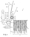
- FIG. 1 is a schematic plan view illustrating a paper sheet pickup apparatus 1 (hereinafter referred to simply as "pickup apparatus 1"), according to the invention, seen from above.
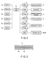
- FIG. 2 is a block diagram illustrating a control system for controlling the operation of the pickup apparatus 1.
- the pickup apparatus 1 comprises an input unit 2, a supply mechanism 3, a pickup belt 4 (pickup member), a negative-pressure chamber 5 (negative-pressure generator), a suction chamber 6, a separation roller 7, conveyor belts 8a and 8b, a plurality of sensors S1 to S6, and a control unit 10 for controlling the operation of the entire apparatus.
- the control unit 10 is connected to the sensors S1 to S6, a motor 11 for operating a floor belt or a backup plate (not shown) incorporated in the supply mechanism 3, a motor 12 for running the pickup belt 4 in the direction indicated by arrow T, a pump 13 (suction unit) for drawing air from the negative-pressure chamber 5, a blower 14 for drawing air from the suction camber 6, a motor 15 for imparting separation torque to the separation roller 7, a pump 16 for generating negative pressure around the periphery of the separation roller 7, and a motor 17 for running the conveyor belts 8a and 8b.
- a motor 11 for operating a floor belt or a backup plate (not shown) incorporated in the supply mechanism 3
- a motor 12 for running the pickup belt 4 in the direction indicated by arrow T
- a pump 13 suction unit
- blower 14 for drawing air from the suction camber 6
- a motor 15 for imparting separation torque to the separation roller 7
- a pump 16 for generating negative pressure around the periphery of the separation roller
- a plurality of paper sheets P are input in an accumulated and upright state.
- the paper sheets P accumulated in the input unit 2 are moved to one side (the left side in FIG. 1 ) by the supply mechanism 3, and the front paper sheet P (the leftmost sheet in FIG. 1 ) is moved to a pickup position S.
- the supply mechanism 3 operates to thereby move the subsequent sheet to the pickup position S.
- the pickup belt 4 runs endlessly around a plurality of pulleys. Part of the pickup belt 4 is brought into contact with the paper sheet P at the pickup position S, and runs at a constant rate in a direction parallel to the surface of the paper sheet P, i.e., in the pickup direction T.
- the negative-pressure chamber 5 faces the inside (reverse side) of the belt 4, and faces the pickup position S with the pickup belt 4 interposed therebetween.
- a plurality of suction holes 4a are formed in the pickup belt 4.
- the negative-pressure chamber 5 has an opening 5a facing the reverse side of the pickup belt 4.
- the pressure in the chamber 5 is reduced, whereby negative pressure is applied to the paper sheet P positioned at the pickup position S through the suction holes 4a.
- the paper sheet P is attached to the surface of the belt 4 by suction force.
- the paper sheet P attached to the pickup belt 4 is picked up from the pickup position S in accordance with the running of the belt 4.
- the paper sheet P picked up from the pickup position S is conveyed by a conveyor path 9 upward in FIG. 1 , and is transferred to a conveyor section formed of conveyor belts 8a and 8b.
- the sensors S1 to S6 provided along the conveyor path 9 are transmission-type optical sensors (only one of the components of each sensor is shown), and used to detect whether the optical axis of each sensor is crossed by the paper sheet P (when the optical axis is crossed by the paper sheet P, the sensor output has a "dark” level, whereas when there is no sheet that crosses the optical axis, the sensor output has a "bright” level). Namely, each of the sensors S1 to S6 detects the front and rear ends of each paper sheet P with respect to the direction of conveyance.
- the suction chamber 6 is provided upstream (at the lower position in FIG. 1 ) of the pickup belt 4 with respect to the direction in which each paper sheet P is picked up, and has an opening 6a opposing the pickup position S.
- air is drawn through the opening 6a of the suction chamber 6, thereby producing an air flow at the pickup position S.
- the air flow functions to quickly draw each paper sheet P received in the inlet unit 2 and fed to the above-mentioned one side of the inlet unit 2 (the most downstream side of the inlet unit 2 with respect to the direction of accumulation).
- the separation roller 7 is provided downstream of the pickup position S with respect to the paper sheet pickup direction (i.e., at the upper side in FIG. 1 ), and faces the pickup belt 4 with the conveyor path 9 interposed therebetween.
- the separation roller 7 includes a substantially cylindrical core 7b with a chamber 7a defined therein, and a substantially cylindrical sleeve 7c rotatably provided on the outer periphery of the core 7b.
- the core 7b has an opening 7d fixedly opening to the conveyor path 9.
- the sleeve 9c has a plurality of suction holes 7e.
- the conveyor belt 8a an endless belt
- the conveyor belt 8b an endless belt
- the conveyor belt 8b an endless belt
- the conveyor path 9 located downstream of the separation roller 7 is defined between the two conveyor belts 8a and 8b.
- the front end of each paper sheet P picked up from the pickup position S is nipped by the nip 8c of the conveyor belts 8a and 8b, and conveyed to the downstream side by the conveyor belts 8a and 8b (conveyor section).
- the pump 13 When each paper sheet P is picked up, the pump 13 is operated to draw air from the negative pressure chamber 5, thereby generating negative pressure on the surface of the pickup belt 4. Further, an air flow directed to the pickup position S is constantly applied by the suction chamber 6 to the paper sheet P earliest accumulated in the inlet unit 2 (i.e., the leftmost one in FIG. 1 ). Namely, the earliest accumulated paper sheet is quickly positioned at the pickup position, and picked up by the pickup belt 4 by a suction force.
- the paper sheet P picked up from the pickup position S is guided to the nip 8c of the conveyor belts 8a and 8b, and then guided to a further downstream position, with the front end of the paper sheet nipped by the nip 8c.
- the fact that the picked paper sheet P has reached the nip 8c is detected when the output of the sensor S5 is changed from the "bright level” to the "dark level.”
- the running rate of the conveyor belts 8a and 8b is set to a value slightly higher than that of the pickup belt 4, which means that the paper sheet P is pulled out by the conveyor belts 8a and 8b.
- a gap is formed between the adjacent paper sheets P by executing on-off control of the negative pressure in the negative-pressure chamber 5, or by intermittently running the pickup belt 4.
- the gap is determined in accordance with the processing rate of paper sheets P in a processing unit (which is not shown or described) connected to the conveyor path 9 and located downstream of the pickup apparatus 1.
- the gap is determined in accordance with the switching rate of a gate (not shown) provided downstream of the conveyor path 9.
- valve device that has an extremely high response rate, can circulate a large amount of air, and can instantly circulate air and stop the circulation of the air.
- Various embodiments of the valve device will now be described.
- FIG. 4 is a schematic perspective view illustrating a valve device 20 according to a first embodiment.
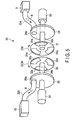
- FIG. 5 is an exploded perspective view illustrating the internal structure of the valve device shown in FIG. 4 .
- the valve device 20 is provided across a suction tube 22 that connects the negative-pressure chamber 5 and the pump 13. As shown in FIGS. 4 and 5 , in the direction (indicated by arrow R) in which air flows when the pump 13 operates, the suction tube 22 is divided into an upstream-side suction tube 22a connected to the negative-pressure chamber 5 located upstream of the valve device 20, and a downstream-side suction tube 22b connected to the pump 13 located downstream of the valve device 20.
- the valve device 20 comprises a first substantially disc-shaped block 24 connected to an end of the upstream-side tube 22a away from the negative-pressure chamber 5, a second substantially disc-shaped block 26 connected to an end of the downstream-side tube 22b away from the pump 13, first and second substantially disc-shaped shielding plates 31 and 32, and two servo motors 33 and 34 for independently rotating the shielding plates 31 and 32, respectively.
- the two servo motors 33 and 34 function as driving units of the present invention, and are connected to the control unit 10 of the pickup apparatus described above.
- the servo motors 33 and 34 are provided outside the first and second blocks 24 and 26, respectively.
- the first embodiment employs the two servo motors 33 and 34 for independently rotating the two shielding plates 31 and 32, the two shielding plates 31 and 32 may be rotated by a single driving unit (not shown).
- the suction tube 22 comprising the upstream and downstream tubes 22a and 22b defines an air passage 23 through the valve device 20.
- the first and second blocks 24 and 26 and the first and second shielding plates 31 and 32 are arranged coaxially and adjacent to each other, with their axes set substantially parallel to the air passage 23.
- FIG. 5 shows the four disk-shaped members 24, 26, 31 and 32 in an axially separate state for facilitating the explanation, they are actually axially adjacent to each other as shown in FIG. 4 .
- the first and second shielding plates 31 and 32 are arranged rotatable (angularly movable) on the plane extending across the air passage 23. Further, the rotary shaft of the servo motor 33 is extended through the central portions of the first and second block 24 and the first shielding plate 31, and the rotary shaft of the servo motor 34 is extended through the central portions of the second block 26 and the second shielding plate 32.
- the rotary shafts of the servo motors 33 and 34 are arranged coaxial.
- the first and second shielding plates 31 and 32 are independently rotated in opposite directions by the servo motors 33 and 34 as indicated by arrows CW and CCW, respectively. More specifically, the first shielding plate 31 is rotated clockwise (in the direction indicated by the arrow CW) when seen from the left side in FIG. 5 . Similarly, the second shielding plate 32 is rotated counterclockwise (in the direction indicated by the arrow CCW) when seen from the left side in FIG. 5 .
- a communication hole 24a is formed through the first block 24 so that it communicates with the upstream-side tube 22a
- a communication hole 26a is formed through the second block 26 so that it communicates with the downstream-side tube 22b.
- the communication holes 24a and 26a are formed at preset corresponding positions away from the axes of rotation of the first and second blocks 24 and 26, respectively.
- the communication holes 24a and 26a are formed coaxial, facing each other, to define the opposite ends of the aforementioned air passage 23.
- a plurality of (three in the embodiment) air passing holes 31a (first air passing holes) and a plurality of (three in the embodiment) air passing holes 32a (second air passing holes) are formed in the first and second shielding plates 31 and 32, respectively. These air passing holes 31a and 32a rotate (angularly move) in accordance with the rotation of the first and second shielding plates 31 and 32.
- the air passing holes 31a and 32a are of a fan shape having diametrically extending edges.
- the air passing holes 31a and 32a overlap with the communication holes 24a and 26a of the first and second blocks 24 and 26, i.e., overlap with the air passage 23 of the suction tube 22 for a relatively long time, while the shielding plates 31 and 32 are rotated.
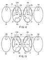
- FIGS. 6 to 15 are views useful in explaining the opening/closing control of the air passage 23 performed by rotating the two shielding plates 31 and 32.
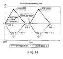
- FIG. 14 is a graph useful in explaining changes in the rotational rate of each of the shielding plates 31 and 32 associated with the operations shown in FIGS. 6 to 13 .
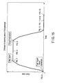
- FIG. 15 is a graph illustrating changes with time in the open area of the air passage 23 associated with the operations shown in FIGS. 6 to 13 . Note that for facilitating the description, FIGS. 6 to 13 show only essential structural elements of the valve device 20.
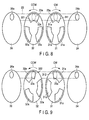
- FIG. 6 shows a state example in which the valve device 20 closes the air passage 23.
- FIGS. 6 to 13 show, using two-dot chain lines, an area 23a in which the air passage 23 overlaps with the shielding plates 31 and 32.
- the two shielding plates 31 and 32 were rotated at various rates only in the directions indicated by the arrows. Specifically, as shown in FIG. 14 , the first shielding plate 31 adjacent to the first block 24 and closer to the negative-pressure chamber 5 is rotated clockwise (in the CW direction or a first direction), and the second shielding plate 32 adjacent to the second block 26 and closer to the pump 13 is rotated counterclockwise (in the CCW direction or a second direction).
- the CW directional leading edge 311 of one of the air passing holes 31a of the first shielding plate 31 crosses the air passage 23
- the CCW directional leading edge 321 of one of the air passing holes 32a of the second shielding plate 32 crosses the air passage 23.
- the aforementioned leading edges 311 and 321 may slightly overlap with each other.
- the shielding plates 31 and 32 are rotated in the respective directions indicated by the arrows, until the state shown in FIG. 7 is assumed. As a result, the air passage 23 is opened. More specifically, the control unit 10 monitors the outputs of the sensors S1 to S6 to determine whether a preceding paper sheet P is transferred onto the conveyor path 9, and issues the "open" instruction for attaching a subsequent paper sheet P to the pickup belt 4.
- the control unit 10 starts to rotate the shielding plates 31 and 32 that are in the standby state shown in FIG. 6 , the angular velocity of each of the shielding plates 31 and 32 is gradually increased from 0 as shown in FIG. 14 .
- the two shielding plates 31 and 32 start to rotate from their angular standby positions, and the air passage 23 is fully opened while the rotation of the shielding plates 31 and 32 is accelerated. Namely, in the state shown in FIG. 7 , the shielding plates 31 and 32 are rotated at the highest rotational rate.
- the air passage 23 can be extremely quickly switched from the closed state to the open state as shown in FIG. 15 , thereby increasing the response rate of the valve device 20.
- the angular moving distance (rotational angle) of each shielding plate 31 or 32, required to shift the air passage 23 from the open state to the closed state becomes longer (larger).
- a long time will be necessary to fully open the air passage 23 after receiving the "open" instruction.
- the first embodiment is designed such that the two shielding plates 31 and 32 start to rotate from their angular standby positions shown in FIG. 6 , and the air passage 23 is fully opened while the rotation of the two shielding plates 31 and 32 is accelerated.
- the air passage 23 is fully opened during acceleration of the shielding plates 31 and 32, it is sufficient if each of the shielding plates 31 and 32 is not decelerated at least until the air passage is opened.
- the control unit 10 decelerates and stops the shielding plates 31 and 32 while the state shown in FIG. 7 is shifted to the FIG. 8 state and then to the FIG. 9 state.
- the shielding plates 31 and 32 are decelerated and almost stopped, and while the FIG. 8 state is shifted to the FIG. 9 state, each of the shielding plates 31 and 32 is rotated slowly to another standby position shown in FIG. 9 .
- the state shown in FIG. 9 now serves as the standby state assumed before blocking the air passage 23.
- the CW directional trailing edge 312 of one of the air passing holes 31a of the first shielding plate 31 is adjacent to an edge portion of the air passage 23 (area 23a)
- the CCW directional trailing edge 322 of one of the air passing hole 32a of the second shielding plate 32 is adjacent to another edge portion of the air passage 23 (area 23a) opposite to the first-mentioned edge portion.
- the two air passing holes 31a and 32a overlap with the air passage 23.
- the rotational angle (moving distance), through which each shielding plate 31 or 32 needs to move to completely block the air passage 23, is an extremely small angle (short distance) corresponding to the angular movements of the trailing edges 312 and 322 of the air passing holes 31a and 32a from the respective edge portions of the air passage 23 to substantially the center of the air passage 23. From this, it is understood that the air passage 23 can be blocked in a very short time.
- control unit 10 decelerates and almost stops the rotation of the shielding plates 31 and 32 while the state shown in FIG. 10 is shifted to the FIG. 11 state and then to the FIG. 12 state. After that, the control unit 10 slowly rotates the shielding plates 31 and 32 until the standby state shown in FIG. 13 (the same state shown in FIG. 6 ) is assumed, and stops them.
- valve device 20 of the first embodiment can instantly open and close the air passage 23 to enable a plurality of paper sheets P to be sequentially picked up at high rate. Further, the pickup apparatus 1 of the first embodiment, which employs the above-described valve device 20, can instantly circulate and block a large amount of air, thereby enabling even relatively heavy paper sheets P to be attached to the pickup belt 4 reliably.
- the conventional solenoid valve is used for the same purpose as the above, it is difficult to simultaneously pass therethrough a large amount of air since the solenoid valve has a significant fluid passage resistance as described above, with the result that the negative-pressure chamber 5 cannot instantly be set to negative pressure. Furthermore, if the fluid passage itself is made thicker, the inertia of the plunger will inevitably be increased, and accordingly, the response rate of the solenoid valve becomes low.
- valve device 20 of the first embodiment can instantly open and close the air passage 23 by simply rotating the motor 27, and hence the response rate of the valve device can be easily enhanced.
- the diameter of the air passage 23 can be set to an arbitrary value, whereby a greater amount of air can be circulated and blocked.
- the valve device 20 of the first embodiment since the valve device 20 of the first embodiment has a structure for linearly passing air, it has almost no air passing resistance and hence can smoothly circulate a large amount of air.
- FIG. 16 is an exploded perspective view illustrating a valve device 30 according to a second embodiment.
- the valve device 30 is provided across the suction tube 22 that connects the negative-pressure chamber 5 to the pump 13, as in the above-described first embodiment, and also across an exhaust tube 28 that connects the negative-pressure chamber 5 and the exhaust port 13a of the pump 13. In other words, the valve device 30 is operated to alternately open/close the suction tube 22 and the exhaust tube 28.
- the exhaust tube 28 comprises an upstream-side exhaust tube 28a located upstream of the valve device 30 with respect to the flow direction (indicated by arrow Q) of air exhausted from the exhaust port 13a of the pump 13, and a downstream-side exhaust tube 28b located downstream of the valve device 30.
- the upstream-side exhaust tube 28a connects the exhaust port 13a of the pump 13 to the communication hole 26b of the second block 26 of the valve device 30, while the downstream-side exhaust tube 28b connects the negative-pressure chamber 5 to the communication hole 24b of the first block 24 of the valve device 30.
- the exhaust tube 28 defines an air passage 29 described later.
- the communication hole 24a of the first block 24, and the communication hole 24b of the first block 24, which is connected to the downstream-side exhaust tube 28b, are formed symmetrical with respect to the rotation axis of the shielding plate 31.
- the communication hole 26a of the second block 26, and the communication hole 26b of the second block 26, which is connected to the upstream-side exhaust tube 28a are formed symmetrical with respect to the rotation axis of the shielding plate 32.
- the communication hole 26b is also formed coaxial with the communication hole 24b of the first block 24. Since the structural elements of the second embodiment other than the above-described ones are similar to those of the valve device 20 of the first embodiment, they will not be described in detail but be only denoted by corresponding reference numbers.
- valve device 30 constructed as above will be described.
- FIGS. 17 to 22 only show essential parts of the valve device 30.
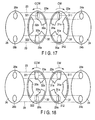
- FIG. 17 shows an example in which the suction tube 22 is blocked and the exhaust tube 28 is open. Namely, in the state shown in FIG. 17 , the air passage 23 (first air passage) defined by the suction tube 22 is blocked (closed), and the air passage 29 (second air passage) defined by the exhaust tube 28 is open. In other words, in the FIG. 17 state, exhaust air is sent from the pump 13 to the negative-pressure chamber 6 to return the internal pressure of the chamber to the atmospheric pressure.
- this state is a standby state assumed before the air passage 23 is open.
- This state also serves as a standby state assumed before the air passage 29 is blocked. Namely, in this state, half of the cross section of the air passage 23 is blocked by the first shielding plate 31, and the other half is blocked by the second shielding plate 32. Thus, the first and second shielding plates 31 and 32 cooperate to completely block the air passage 23. Also in this state, the other air passage 29 overlaps with the air passing hole 31a of the first shielding plate 31 and with the air passing holes 32a of the second shielding plate 32. Thus, the first and second shielding plates 31 and 32 cooperate to completely open the air passage 29.
- the CW directional leading edge 311 of one of the air passing holes 31a of the first shielding plate 31 crosses the air passage 23
- the CCW directional leading edge 321 of one of the air passing holes 32a of the second shielding plate 32 crosses the air passage 23.
- the one air passing hole 31a does not overlap with the one air passing hole 32a within the cross section of the air passage 23.
- the CW directional trailing edge 312 of another air passing hole 31a of the first shielding plate 31 is adjacent to an edge portion of the air passage 29, and the CCW directional trailing edge 322 of another air passing hole 32a of the second shielding plate 32 with respect to the is adjacent to another edge portion of the air passage 29 opposite to the first-mentioned edge portion.
- the two air passing holes 31a and 32a completely overlap with the air passage 29.
- the air passage 23 can be switched from the closed state to the open state within an extremely short time, and the air passage 29 can be switched from the open state to the closed state within the extremely short time.
- the valve device 30 can realize a very high response rate. To this end, it is important to set the FIG. 17 state as the standby state before opening the air passage 23 and closing the air passage 29, and to rotate the shielding plates 31 and 32 in different directions from their angular standby positions shown in FIG. 17 .
- the control unit 10 decelerates and stops the two shielding plates 31 and 32 while the FIG. 18 state is shifted to the FIG. 19 state and then to the FIG. 20 state.
- the two shielding plates 31 and 32 are decelerated and almost stopped, and while the FIG. 19 state is shifted to the FIG. 20 state, the two shielding plates 31 and 32 are slowly rotated to the other angular standby positions. Namely, at this time, the standby state shown in FIG. 20 , which is assumed before the air passage 23 is blocked and the air passage 29 is opened, is established.
- the CW directional trailing edge 312 of one of the air passing holes 31a of the first shielding plate 31 is adjacent to an edge portion of the air passage 23, and the CCW directional trailing edge 322 of one of the air passing holes 32a of the second shielding plate 32 is adjacent to another edge portion of the air passage 23 opposite to the first mentioned edge portion.
- the one air passing hole 31a and the one air passing hole 32a each completely overlap with the air passage 23.
- the CW directional leading edge 311 of another air passing holes 31a of the first shielding plate 31 crosses the air passage 29, and the CCW directional leading edge 321 of another air passing holes 32a of the second shielding plate 32 crosses the air passage 29.
- said another air passing hole 31a does not overlap with said another air passing hole 32a within the air passage 29.
- the air passage 23 is instantly closed, and the air passage 29 is instantly opened. Also in this case, the air passage 23 and the air passage 29 are closed and opened, respectively, during the acceleration of the shielding plates 31 and 32. Thus, the shielding plates 31 and 32 are prevented from deceleration.
- the rotational angle (moving distance), through which each shielding plate 31 or 32 needs to move to completely block the air passage 23 and fully open the air passage 29, is an extremely small angle (short distance) corresponding to the angular movements of the trailing edges 312 and 322 of the air passing holes 31a and 32a from the respective edge portions of the air passage 23 to substantially the center of the air passage 23. From this, it is understood that the air passage 23 can be blocked and the air passage 29 be opened in a very short time.
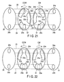
- control unit 10 decelerates and stops the shielding plates 31 and 32 while the FIG. 21 state is shifted to the FIG. 22 state and then returned to the FIG. 17 state.
- FIGS. 17 to 22 The operations shown in FIGS. 17 to 22 are repeated to control the opening/closing operation of the valve device 30, thereby opening/closing the suction tube 22 and closing/opening the exhaust tube 28.
- negative pressure is applied to each paper sheet P set at the pickup position S to thereby attach the same to the pickup belt 4.
- This enables paper sheets P to be intermittently picked up to the conveyor path 9 one by one, and enables the internal pressure of the negative-pressure chamber 5 to be returned to the atmospheric pressure instantly.
- three paper sheets P can be picked up while the shielding plates 31 and 32 are each rotated through 360°.
- the second embodiment can provide the same advantage as the first embodiment, and can also instantly introduce a large amount of air into the negative-pressure chamber 5 when releasing the paper sheet P from the pickup belt.
- a pickup member may be a rotor that has a plurality of suction holes and is rotatable in the sheet pickup direction.
- the invention is limited to this.
- three or more shielding plates may be employed to make them cooperate to open/close a plurality of air passages. In this case, it is difficult to arrange all shielding plates coaxially, and hence the shielding plates may be made overlap each other so that their rotational axes are arranged parallel to each other.
- valve device 20 (30) opens and closes a single air passage 23 or simultaneously opens and closes two air passages 23 and 29, the invention is not limited to this structure.
- the number of air passages controlled by a single valve device may be set arbitrarily.
- the two shielding plates cooperate to completely block the air passage(s) in a standby state assumed before opening the air passage, it is not always necessary to completely block the air passage, but a slight clearance may be defined between the two shielding plates.
Landscapes
- Engineering & Computer Science (AREA)
- Mechanical Engineering (AREA)
- Sheets, Magazines, And Separation Thereof (AREA)
- Multiple-Way Valves (AREA)
- Sliding Valves (AREA)
- Electrically Driven Valve-Operating Means (AREA)
Abstract
A valve device (20) is provided with a first block (24) connected to an upstream-side suction tube (22a) that is connected to a negative-pressure chamber (5), a second block (26) connected to a downstream-side suction tube (22b) that is connected to a pump (13), first and second shielding plates (31, 32) rotatably interposed between the first and second blocks, and servo motors (33, 34) for rotating the shielding plates (31, 32). Each of the shielding plates (31, 32) has a plurality of air passing holes (31a, 32a), and are rotated in opposite directions.
Description
- The present invention relates to a valve device for circulating and interrupting a fluid, and more particularly, to a paper sheet pickup apparatus for picking up sheets of paper one by one by attaching each sheet to a belt using a suction force.
- There is a conventional standard paper sheet pickup apparatus, in which a belt with holes runs along mail matters to attach thereon each mail matter by drawing each mail matter through the holes of the belt using a suction nozzle provided near the reverse side of the belt, thereby picking up the mail matters one by one (see, for example,
US Patent No. 5,391,051 ). This apparatus comprises a solenoid valve interposed between the suction nozzle and a vacuum tank. - When operating the apparatus to pick up mail matters, the belt runs, and each mail matter is attached to the belt by the suction force of the suction nozzle that is generated when the solenoid valve is open. To sequentially pick up mail matters, the solenoid valve is periodically closed in accordance with the pickup timing of each mail matter, thereby forming a gap between a currently picked up mail matter and a mail matter to be subsequently picked up.
-
FIGS. 23 and 24 are schematic views illustrating aconventional solenoid valve 100.FIG. 23 shows a state in which thesolenoid valve 100 is open, andFIG. 24 shows a state in which thesolenoid valve 100 is closed. - In general, the
solenoid valve 100 comprises acoil 104 for axially moving a substantiallycylindrical plunger 102, a chamber 106 (shown only inFIG. 23 ) containing theplunger 102, and twoholes chamber 106, through which twopipes chamber 106. When using thesolenoid valve 100 in the apparatus disclosed in the above-mentioned US patent, the twopipes - When opening the
solenoid valve 100, thecoil 104 is excited to pull theplunger 102 out of thechamber 106 to make the twoholes chamber 106. In contrast, when closing thesolenoid valve 100, the excitation of thecoil 104 is interrupted to thereby push theplunger 102 into thechamber 106 and block the twoholes fluid path 110 that connects thepipes - The
solenoid valve 100 is opened and closed by axially moving theplunger 102. Therefore, great inertia occurs when opening/closing thesolenoid valve 100. In particular, when the diameter of thepipes solenoid valve 100 is increased to increase the flow of air, it is necessary to also increase the diameter of theplunger 102 for blocking theholes - Further, when opening the
solenoid valve 100, much time is required until the pressure in thechamber 106 reaches a preset value after thecoil 104 is excited to move theplunger 102 and introduce air into thechamber 106. Thus, the response rate of thesolenoid valve 100, i.e., the rate of starting the circulation of air after the excitation of thecoil 104, is low. Similarly, when closing thesolenoid valve 100, the moving rate of theplunger 102 is low since theplunger 102 is pushed into thechamber 106 against air of the preset pressure. Namely, the response rate of theconventional solenoid valve 100 is low both when thecoil 104 is excited, and when the excitation of thecoil 104 is stopped. - This being so, if the
solenoid valve 100 is used between the suction nozzle and the vacuum tank employed in the sheet (mail matter) pickup apparatus disclosed in the above-mentioned US patent, the mail matter pickup rate will inevitably be low because of the low response rate of thesolenoid valve 100 itself. - Further, if the
solenoid valve 100 is used in the sheet (mail matter) pickup apparatus disclosed in the above-mentioned US patent, it will be difficult to attach, by suction force, a relatively large and heavy mail matter on the belt with holes. Namely, when thesolenoid valve 100 assumes the open state shown inFIG. 23 , it is necessary to circulate air through a fluid passage bent at several points. In this case, the passing resistance of the air is not small, and hence it is difficult to increase the flow rate. This makes it difficult to draw a relatively large amount of air through the suction nozzle, i.e., difficult to attach a relatively heavy mail matter on the belt by suction force. - It is an object of the present invention to provide a valve device capable of circulating a relatively large amount of fluid and interrupting the circulation at high response rate.
- It is another object of the present invention to provide a paper sheet pickup apparatus capable of easily picking up a relatively heavy paper sheet and picking up sheets of paper at high pickup rate.
- In accordance with an aspect of the invention, there is provided a valve device comprising: a first shielding plate movable across a fluid passage for passing a fluid therethrough, the first shielding plate including a first fluid passing hole which overlaps with the fluid passage when the first shielding plate is moving; a second shielding plate adjacent to the first shielding plate, movable across the fluid passage and including a second fluid passing hole which overlaps with the fluid passage when the second shielding plate is moving; and a driving unit configured to make the first and second shielding plates cooperate with each other to close and open the fluid passage.
- In the above structure, the fluid passage can instantly be opened simply by angularly moving the first and second shielding plates, and hence circulation of a relatively large amount of fluid can be started immediately after the fluid passage is opened. Thus, the valve device of the invention is excellent in response rate, and hence can instantly circulate and block a relatively large amount of fluid.
- In accordance with another aspect of the invention, there is provided a valve device comprising: a first shielding plate rotatable across a first fluid passage for passing a fluid therethrough, and across a second fluid passage separate from the first fluid passage, the first shielding plate including a plurality of first fluid passing holes which overlap with the first and second fluid passages when the first shielding plate is rotating; a second shielding plate adjacent to the first shielding plate, rotatable across the first and second fluid passages and including a plurality of second fluid passing holes which overlap with the first and second fluid passages when the second shielding plate is rotating; and a driving unit configured to make the first and second shielding plates cooperate with each other to close and open the first and second fluid passages.
- In accordance with yet another aspect of the invention, there is provided a paper sheet pickup apparatus comprising: an input unit configured to receive a plurality of paper sheets accumulated; a pickup member including a suction hole and configured to run along one of accumulated paper sheets, the one paper sheet being positioned at a most downstream side with respect to a direction of accumulation; a negative-pressure generating unit configured to draw air through the suction hole from a reverse side of the pickup member, thereby generating negative pressure on a surface of the pickup member to attach thereon the one paper sheet; a suction unit connected to the negative-pressure generating unit via a fluid passage; and a valve device provided across the fluid passage, wherein the valve device comprises: a first shielding plate movable across the fluid passage, and including a first fluid passing hole which overlaps with the fluid passage when the first shielding plate is moving; a second shielding plate adjacent to the first shielding plate, movable across the fluid passage, and including a second fluid passing hole which overlaps with the fluid passage when the second shielding plate is moving; and a driving unit configured to make the first and second shielding plates cooperate with each other to close and open the fluid passage.
- In the invention constructed as above, a large amount of air can instantly be drawn from the negative-pressure chamber when picking up a paper sheet, thereby instantly reducing the internal pressure of the negative-pressure chamber. Accordingly, a relatively heavy paper sheet can easily be picked up, which enables high rate pickup of paper sheets.
- In accordance with yet further aspect of the invention, there is provided a paper sheet pickup apparatus comprising: an input unit configured to receive a plurality of paper sheets accumulated; a pickup member including a suction hole and configured to run along one of accumulated paper sheets, the one paper sheet being positioned at a most downstream side with respect to a direction of accumulation; a negative-pressure generating unit configured to draw air through the suction hole from a reverse side of the pickup member, thereby generating negative pressure on a surface of the pickup member to attach thereon the one paper sheet; a suction unit connected to the negative-pressure generating unit via a first fluid passage; and a valve device provided across the first fluid passage and across a second fluid passage, wherein the valve device comprises: a first shielding plate rotatable across the first and second fluid passages, and including a plurality of first fluid passing holes which overlap with the first and second fluid passages when the first shielding plate is rotating; a second shielding plate adjacent to the first shielding plate, rotatable across the first and second fluid passages and including a plurality of second fluid passing holes which overlap with the first and second fluid passages when the second shielding plate is rotating; and a driving unit configured to make the first and second shielding plates cooperate with each other to close and open the first and second fluid passages.
- The invention can be more fully understood from the following detailed description when taken in conjunction with the accompanying drawings, in which:
-
FIG. 1 is a schematic plan view illustrating a paper sheet pickup apparatus, according to the invention, seen from above; -
FIG. 2 is a block diagram illustrating a control system for controlling the operation of the paper sheet pickup apparatus shown inFIG. 1 ; -
FIG. 3 is a partially enlarged view illustrating a pickup belt incorporated in the paper sheet pickup apparatus shown inFIG. 1 ; -
FIG. 4 is a schematic perspective view illustrating a valve device according to a first embodiment and incorporated in the paper sheet pickup apparatus shown inFIG. 1 between a negative-pressure chamber and a pump that are incorporated in the same apparatus; -
FIG. 5 is an exploded perspective view illustrating the valve device shown inFIG. 4 ; -
FIG. 6 is a view useful in explaining the operation of the valve device shown inFIG. 5 ; -
FIG. 7 is a view useful in explaining the operation of the valve device shown inFIG. 5 ; -
FIG. 8 is a view useful in explaining the operation of the valve device shown inFIG. 5 ; -
FIG. 9 is a view useful in explaining the operation of the valve device shown inFIG. 5 ; -
FIG. 10 is a view useful in explaining the operation of the valve device shown inFIG. 5 ; -
FIG. 11 is a view useful in explaining the operation of the valve device shown inFIG. 5 ; -
FIG. 12 is a view useful in explaining the operation of the valve device shown inFIG. 5 ; -
FIG. 13 is a view useful in explaining the operation of the valve device shown inFIG. 5 ; -
FIG. 14 is a graph indicating changes in the rotational rate of each of two shielding plates, which are assumed when the valve device operates as shown inFIGS. 6 to 13 ; -
FIG. 15 is a graph indicating changes with time in the open area of a fluid passage, which are assumed when the valve device operates as shown inFIGS. 6 to 13 ; -
FIG. 16 is an exploded perspective view illustrating a valve device according to a second embodiment and incorporated in the paper sheet pickup apparatus shown inFIG. 1 between the negative-pressure chamber and the pump that are incorporated in the same apparatus; -
FIG. 17 is a view useful in explaining the operation of the valve device shown inFIG. 16 ; -
FIG. 18 is a view useful in explaining the operation of the valve device shown inFIG. 16 ; -
FIG. 19 is a view useful in explaining the operation of the valve device shown inFIG. 16 ; -
FIG. 20 is a view useful in explaining the operation of the valve device shown inFIG. 16 ; -
FIG. 21 is a view useful in explaining the operation of the valve device shown inFIG. 16 ; -
FIG. 22 is a view useful in explaining the operation of the valve device shown inFIG. 16 ; -
FIG. 23 is a schematic view illustrating the open state of a conventional standard solenoid valve; and -
FIG. 24 is a schematic view illustrating the closed state of the solenoid valve shown inFIG. 23 . - Embodiments of the invention will be described in detail with reference to the accompanying drawings.
-
FIG. 1 is a schematic plan view illustrating a paper sheet pickup apparatus 1 (hereinafter referred to simply as "pickup apparatus 1"), according to the invention, seen from above.FIG. 2 is a block diagram illustrating a control system for controlling the operation of the pickup apparatus 1. - The pickup apparatus 1 comprises an
input unit 2, asupply mechanism 3, a pickup belt 4 (pickup member), a negative-pressure chamber 5 (negative-pressure generator), asuction chamber 6, aseparation roller 7,conveyor belts control unit 10 for controlling the operation of the entire apparatus. - The
control unit 10 is connected to the sensors S1 to S6, amotor 11 for operating a floor belt or a backup plate (not shown) incorporated in thesupply mechanism 3, amotor 12 for running thepickup belt 4 in the direction indicated by arrow T, a pump 13 (suction unit) for drawing air from the negative-pressure chamber 5, ablower 14 for drawing air from thesuction camber 6, amotor 15 for imparting separation torque to theseparation roller 7, apump 16 for generating negative pressure around the periphery of theseparation roller 7, and amotor 17 for running theconveyor belts - In the
input unit 2, a plurality of paper sheets P are input in an accumulated and upright state. The paper sheets P accumulated in theinput unit 2 are moved to one side (the left side inFIG. 1 ) by thesupply mechanism 3, and the front paper sheet P (the leftmost sheet inFIG. 1 ) is moved to a pickup position S. Whenever the front paper sheet P moved to the pickup position S is picked up, thesupply mechanism 3 operates to thereby move the subsequent sheet to the pickup position S. - The
pickup belt 4 runs endlessly around a plurality of pulleys. Part of thepickup belt 4 is brought into contact with the paper sheet P at the pickup position S, and runs at a constant rate in a direction parallel to the surface of the paper sheet P, i.e., in the pickup direction T. The negative-pressure chamber 5 faces the inside (reverse side) of thebelt 4, and faces the pickup position S with thepickup belt 4 interposed therebetween. - As shown in
FIG. 3 , a plurality ofsuction holes 4a are formed in thepickup belt 4. The negative-pressure chamber 5 has anopening 5a facing the reverse side of thepickup belt 4. When thepickup belt 4 is run to draw air from the negative-pressure chamber 5, the pressure in thechamber 5 is reduced, whereby negative pressure is applied to the paper sheet P positioned at the pickup position S through thesuction holes 4a. As a result, the paper sheet P is attached to the surface of thebelt 4 by suction force. The paper sheet P attached to thepickup belt 4 is picked up from the pickup position S in accordance with the running of thebelt 4. - The paper sheet P picked up from the pickup position S is conveyed by a
conveyor path 9 upward inFIG. 1 , and is transferred to a conveyor section formed ofconveyor belts conveyor path 9 are transmission-type optical sensors (only one of the components of each sensor is shown), and used to detect whether the optical axis of each sensor is crossed by the paper sheet P (when the optical axis is crossed by the paper sheet P, the sensor output has a "dark" level, whereas when there is no sheet that crosses the optical axis, the sensor output has a "bright" level). Namely, each of the sensors S1 to S6 detects the front and rear ends of each paper sheet P with respect to the direction of conveyance. - The
suction chamber 6 is provided upstream (at the lower position inFIG. 1 ) of thepickup belt 4 with respect to the direction in which each paper sheet P is picked up, and has anopening 6a opposing the pickup position S. When theblower 14 is operated, air is drawn through theopening 6a of thesuction chamber 6, thereby producing an air flow at the pickup position S. The air flow functions to quickly draw each paper sheet P received in theinlet unit 2 and fed to the above-mentioned one side of the inlet unit 2 (the most downstream side of theinlet unit 2 with respect to the direction of accumulation). - The
separation roller 7 is provided downstream of the pickup position S with respect to the paper sheet pickup direction (i.e., at the upper side inFIG. 1 ), and faces thepickup belt 4 with theconveyor path 9 interposed therebetween. Theseparation roller 7 includes a substantiallycylindrical core 7b with achamber 7a defined therein, and a substantiallycylindrical sleeve 7c rotatably provided on the outer periphery of thecore 7b. Thecore 7b has anopening 7d fixedly opening to theconveyor path 9. The sleeve 9c has a plurality ofsuction holes 7e. With this structure, when thepump 16 is operated to draw air from thechamber 7a of thecore 7b, negative pressure occurs at the periphery of theseparation roller 7 via the suction holes 7e of thesleeve 7c that rotates around thecore 7b. - Namely, by applying, to the
sleeve 7c, separation torque that exerts in a direction opposite to the paper sheet pickup direction, using themotor 15, and producing negative pressure around the outer periphery of thesleeve 7c, using thepump 16, a few paper sheets P picked up unintentionally simultaneously with a leading paper sheet P when the leading paper sheet is picked up from the pickup position S can be separated from the leading paper sheet. - The
conveyor belt 8a, an endless belt, is tensioned (at the left side inFIG. 1 ), opposing theseparation roller 7 with theconveyor path 9 interposed therebetween. Further, theconveyor belt 8b, an endless belt, is tensioned, opposing theconveyor belt 8a with theconveyor path 9 interposed therebetween. Thus, theconveyor path 9 located downstream of theseparation roller 7 is defined between the twoconveyor belts nip 8c of theconveyor belts conveyor belts - A description will now be given of the operation of feeding, one by one onto the
conveyor path 9, a plurality of paper sheets P received in theinlet unit 2. - When a plurality of paper sheets P are fed from the
inlet unit 2 to the pickup apparatus 1, they are sequentially supplied by thesupply mechanism 3 to the pickup position S, and are drawn by thepickup belt 4 and fed onto theconveyor path 9. The paper sheets P conveyed through theconveyor path 9 are monitored in conveyor position and state by thecontrol unit 10 via the sensors S1 to S6. - When each paper sheet P is picked up, the
pump 13 is operated to draw air from thenegative pressure chamber 5, thereby generating negative pressure on the surface of thepickup belt 4. Further, an air flow directed to the pickup position S is constantly applied by thesuction chamber 6 to the paper sheet P earliest accumulated in the inlet unit 2 (i.e., the leftmost one inFIG. 1 ). Namely, the earliest accumulated paper sheet is quickly positioned at the pickup position, and picked up by thepickup belt 4 by a suction force. - The paper sheet P picked up from the pickup position S is guided to the nip 8c of the
conveyor belts nip 8c. The fact that the picked paper sheet P has reached thenip 8c is detected when the output of the sensor S5 is changed from the "bright level" to the "dark level." At this time, the running rate of theconveyor belts pickup belt 4, which means that the paper sheet P is pulled out by theconveyor belts - When one or more paper sheets P are picked up simultaneously with a paper sheet P firstly fed to the pickup position S, they are separated from the latter sheet by the
separation roller 7. At this time, negative pressure is produced on the periphery of theseparation roller 7, and separation torque is exerted on thesleeve 7c in a direction opposite to the pickup direction. When a single paper sheet P is normally picked up, thesleeve 7c of theseparation roller 7 is rotated in the pickup direction. In contrast, when two or more paper sheets are simultaneously picked up, thesleeve 7c is rotated in a direction opposite to the above, whereby the second and later paper sheets are returned and separated from the first paper sheet. - When superposed paper sheets P are separated and fed to the
conveyor path 9 one by one, as described above, a gap is formed between the adjacent paper sheets P by executing on-off control of the negative pressure in the negative-pressure chamber 5, or by intermittently running thepickup belt 4. The gap is determined in accordance with the processing rate of paper sheets P in a processing unit (which is not shown or described) connected to theconveyor path 9 and located downstream of the pickup apparatus 1. In addition to this structure, or alternatively, the gap is determined in accordance with the switching rate of a gate (not shown) provided downstream of theconveyor path 9. - For instance, to enhance the processing efficiency of the processing unit located downstream and impart a sufficient processing time, it is desirable to control the gap between adjacent paper sheets to a desired length. However, in the method of forming a gap by intermittently operating the
pickup belt 4, it is difficult to highly accurately control the times required for accelerating and decelerating the belt, and hence slippage may occur between the belt and each paper sheet when the belt is accelerated or decelerated. - Further, to control the gap between adjacent paper sheets, another method is possible, in which the above-mentioned conventional solenoid valve is provided across the line connecting the
pump 13 to the negative-pressure chamber 5 to open/close the solenoid valve, thereby on/off controlling the negative pressure in the negative-pressure chamber 5 and hence controlling the gap. In this method, however, since the response rate of the solenoid valve itself is low, it is difficult to accurately adjust the gap between adjacent paper sheets to a desired value. - To accurately adjust the gap, the inventors of the present invention have developed a valve device that has an extremely high response rate, can circulate a large amount of air, and can instantly circulate air and stop the circulation of the air. Various embodiments of the valve device will now be described.
-
FIG. 4 is a schematic perspective view illustrating avalve device 20 according to a first embodiment.FIG. 5 is an exploded perspective view illustrating the internal structure of the valve device shown inFIG. 4 . - The
valve device 20 is provided across a suction tube 22 that connects the negative-pressure chamber 5 and thepump 13. As shown inFIGS. 4 and5 , in the direction (indicated by arrow R) in which air flows when thepump 13 operates, the suction tube 22 is divided into an upstream-side suction tube 22a connected to the negative-pressure chamber 5 located upstream of thevalve device 20, and a downstream-side suction tube 22b connected to thepump 13 located downstream of thevalve device 20. - As shown in
FIG. 5 , thevalve device 20 comprises a first substantially disc-shapedblock 24 connected to an end of the upstream-side tube 22a away from the negative-pressure chamber 5, a second substantially disc-shapedblock 26 connected to an end of the downstream-side tube 22b away from thepump 13, first and second substantially disc-shapedshielding plates servo motors plates - The two
servo motors control unit 10 of the pickup apparatus described above. Theservo motors second blocks servo motors plates plates - As indicated by the broken line in
FIG. 4 , the suction tube 22 comprising the upstream anddownstream tubes air passage 23 through thevalve device 20. The first andsecond blocks second shielding plates air passage 23. Namely, althoughFIG. 5 shows the four disk-shapedmembers FIG. 4 . - The first and
second shielding plates air passage 23. Further, the rotary shaft of theservo motor 33 is extended through the central portions of the first andsecond block 24 and thefirst shielding plate 31, and the rotary shaft of theservo motor 34 is extended through the central portions of thesecond block 26 and thesecond shielding plate 32. The rotary shafts of theservo motors - The first and
second shielding plates servo motors first shielding plate 31 is rotated clockwise (in the direction indicated by the arrow CW) when seen from the left side inFIG. 5 . Similarly, thesecond shielding plate 32 is rotated counterclockwise (in the direction indicated by the arrow CCW) when seen from the left side inFIG. 5 . - A
communication hole 24a is formed through thefirst block 24 so that it communicates with the upstream-side tube 22a, and acommunication hole 26a is formed through thesecond block 26 so that it communicates with the downstream-side tube 22b. The communication holes 24a and 26a are formed at preset corresponding positions away from the axes of rotation of the first andsecond blocks aforementioned air passage 23. - A plurality of (three in the embodiment)
air passing holes 31a (first air passing holes) and a plurality of (three in the embodiment)air passing holes 32a (second air passing holes) are formed in the first andsecond shielding plates air passing holes second shielding plates air passing holes air passing holes communication holes second blocks air passage 23 of the suction tube 22 for a relatively long time, while the shieldingplates - Referring now to
FIGS. 6 to 15 , a description will be given of the operation of thevalve device 20 constructed as above.FIGS. 6 to 13 are views useful in explaining the opening/closing control of theair passage 23 performed by rotating the two shieldingplates FIG. 14 is a graph useful in explaining changes in the rotational rate of each of the shieldingplates FIGS. 6 to 13 .FIG. 15 is a graph illustrating changes with time in the open area of theair passage 23 associated with the operations shown inFIGS. 6 to 13 . Note that for facilitating the description,FIGS. 6 to 13 show only essential structural elements of thevalve device 20. -
FIG. 6 shows a state example in which thevalve device 20 closes theair passage 23.FIGS. 6 to 13 show, using two-dot chain lines, anarea 23a in which theair passage 23 overlaps with the shieldingplates plates FIG. 14 , thefirst shielding plate 31 adjacent to thefirst block 24 and closer to the negative-pressure chamber 5 is rotated clockwise (in the CW direction or a first direction), and thesecond shielding plate 32 adjacent to thesecond block 26 and closer to thepump 13 is rotated counterclockwise (in the CCW direction or a second direction). - In the state shown in
FIG. 6 , the two shieldingplates air passage 23 is opened. In the graphs ofFIGS. 14 and15 , the time at which the standby state shown inFIG. 6 is assumed is set as the origin. In this state, approx. half of the cross section of theair passage 23 is blocked (closed) by thefirst shielding plate 31, and the other half is blocked by thesecond shielding plate 32. Thus, the first andsecond shielding plates air passage 23. - More specifically, in the state shown in
FIG. 6 , the CW directionalleading edge 311 of one of theair passing holes 31a of thefirst shielding plate 31 crosses theair passage 23, and the CCW directionalleading edge 321 of one of theair passing holes 32a of thesecond shielding plate 32 crosses theair passage 23. In this state, it is necessary to set the twoair passing holes edges - If in this state, an "open" instruction is issued from the
control unit 10, the shieldingplates FIG. 7 is assumed. As a result, theair passage 23 is opened. More specifically, thecontrol unit 10 monitors the outputs of the sensors S1 to S6 to determine whether a preceding paper sheet P is transferred onto theconveyor path 9, and issues the "open" instruction for attaching a subsequent paper sheet P to thepickup belt 4. - Since at this time, the
control unit 10 starts to rotate theshielding plates FIG. 6 , the angular velocity of each of the shieldingplates FIG. 14 . As can be understood fromFIG. 14 , the two shieldingplates air passage 23 is fully opened while the rotation of the shieldingplates FIG. 7 , the shieldingplates - Thus, by fully opening the
air passage 23 during acceleration of the shieldingplates air passage 23 can be extremely quickly switched from the closed state to the open state as shown inFIG. 15 , thereby increasing the response rate of thevalve device 20. To this end, it is important to make theair passage 23 assume the state shown inFIG. 6 when it is in the standby state before it is open. It is also important to rotate theshielding plates FIG. 6 . - On the other hand, if it is necessary to simultaneously open the air passage and stop the shielding
plates plates air passage 23 is fully opened after an "open" instruction is issued. - Further, if the
first shielding plate 31 is rotated from the position in which thefront edge 311 of theair passing hole 31a does not cross theair passage 23, and thesecond shielding plate 32 is rotated from the position in which thefront edge 321 of theair passing hole 32a does not cross theair passage 23, thereby opening theair passage 23, the angular moving distance (rotational angle) of each shieldingplate air passage 23 from the open state to the closed state, becomes longer (larger). Thus, a long time will be necessary to fully open theair passage 23 after receiving the "open" instruction. - In light of the above, the first embodiment is designed such that the two shielding
plates FIG. 6 , and theair passage 23 is fully opened while the rotation of the two shieldingplates air passage 23 is fully opened during acceleration of the shieldingplates plates - After that, the
control unit 10 decelerates and stops the shieldingplates FIG. 7 is shifted to theFIG. 8 state and then to theFIG. 9 state. In the first embodiment, while the state shown inFIG. 7 is shifted to theFIG. 8 state, the shieldingplates FIG. 8 state is shifted to theFIG. 9 state, each of the shieldingplates FIG. 9 . Thus, the state shown inFIG. 9 now serves as the standby state assumed before blocking theair passage 23. - More specifically, in the standby state shown in
FIG. 9 , the CW directional trailingedge 312 of one of theair passing holes 31a of thefirst shielding plate 31 is adjacent to an edge portion of the air passage 23 (area 23a), and the CCWdirectional trailing edge 322 of one of theair passing hole 32a of thesecond shielding plate 32 is adjacent to another edge portion of the air passage 23 (area 23a) opposite to the first-mentioned edge portion. In this state, the twoair passing holes air passage 23. - When the two shielding
plates FIG. 9 to the angular positions shown inFIG. 10 in accordance with a "close" instruction issued from thecontrol unit 10, theair passage 23 is instantly closed. Also in this case, it is important to block theair passage 23 during acceleration of the shieldingplates FIG. 14 , namely, the shieldingplates plate air passage 23, is an extremely small angle (short distance) corresponding to the angular movements of the trailingedges air passing holes air passage 23 to substantially the center of theair passage 23. From this, it is understood that theair passage 23 can be blocked in a very short time. - To block the
air passage 23 in a short time, it is important to stop the shieldingplates FIG. 9 assumed before blocking theair passage 23. By establishing this standby state, the rate of the closing operation of thevalve device 20 can be increased. When the state shown inFIG. 10 is assumed, the shieldingplates - Thereafter, the
control unit 10 decelerates and almost stops the rotation of the shieldingplates FIG. 10 is shifted to theFIG. 11 state and then to theFIG. 12 state. After that, thecontrol unit 10 slowly rotates the shieldingplates FIG. 13 (the same state shown inFIG. 6 ) is assumed, and stops them. - The operations shown in
FIGS. 6 to 13 are repeated to control the opening and closing of thevalve device 20, thereby opening and closing the suction tube 22 to apply negative pressure to each paper sheet P set at the pickup position S and attach the same to thepickup belt 4. As a result, paper sheets P are intermittently picked up to theconveyor path 9 one by one. In the case of using thevalve device 20 of the first embodiment, three paper sheets P can be picked up while the shieldingplates - As described above, the
valve device 20 of the first embodiment can instantly open and close theair passage 23 to enable a plurality of paper sheets P to be sequentially picked up at high rate. Further, the pickup apparatus 1 of the first embodiment, which employs the above-describedvalve device 20, can instantly circulate and block a large amount of air, thereby enabling even relatively heavy paper sheets P to be attached to thepickup belt 4 reliably. - If the conventional solenoid valve is used for the same purpose as the above, it is difficult to simultaneously pass therethrough a large amount of air since the solenoid valve has a significant fluid passage resistance as described above, with the result that the negative-
pressure chamber 5 cannot instantly be set to negative pressure. Furthermore, if the fluid passage itself is made thicker, the inertia of the plunger will inevitably be increased, and accordingly, the response rate of the solenoid valve becomes low. - In contrast, the
valve device 20 of the first embodiment can instantly open and close theair passage 23 by simply rotating the motor 27, and hence the response rate of the valve device can be easily enhanced. Further, in thevalve device 20 of the first embodiment, the diameter of theair passage 23 can be set to an arbitrary value, whereby a greater amount of air can be circulated and blocked. Yet further, since thevalve device 20 of the first embodiment has a structure for linearly passing air, it has almost no air passing resistance and hence can smoothly circulate a large amount of air. -
FIG. 16 is an exploded perspective view illustrating avalve device 30 according to a second embodiment. Thevalve device 30 is provided across the suction tube 22 that connects the negative-pressure chamber 5 to thepump 13, as in the above-described first embodiment, and also across an exhaust tube 28 that connects the negative-pressure chamber 5 and theexhaust port 13a of thepump 13. In other words, thevalve device 30 is operated to alternately open/close the suction tube 22 and the exhaust tube 28. - The exhaust tube 28 comprises an upstream-
side exhaust tube 28a located upstream of thevalve device 30 with respect to the flow direction (indicated by arrow Q) of air exhausted from theexhaust port 13a of thepump 13, and a downstream-side exhaust tube 28b located downstream of thevalve device 30. The upstream-side exhaust tube 28a connects theexhaust port 13a of thepump 13 to thecommunication hole 26b of thesecond block 26 of thevalve device 30, while the downstream-side exhaust tube 28b connects the negative-pressure chamber 5 to thecommunication hole 24b of thefirst block 24 of thevalve device 30. The exhaust tube 28 defines anair passage 29 described later. - The
communication hole 24a of thefirst block 24, and thecommunication hole 24b of thefirst block 24, which is connected to the downstream-side exhaust tube 28b, are formed symmetrical with respect to the rotation axis of the shieldingplate 31. Similarly, thecommunication hole 26a of thesecond block 26, and thecommunication hole 26b of thesecond block 26, which is connected to the upstream-side exhaust tube 28a, are formed symmetrical with respect to the rotation axis of the shieldingplate 32. Thecommunication hole 26b is also formed coaxial with thecommunication hole 24b of thefirst block 24. Since the structural elements of the second embodiment other than the above-described ones are similar to those of thevalve device 20 of the first embodiment, they will not be described in detail but be only denoted by corresponding reference numbers. - The operation of the
valve device 30 constructed as above will be described. - For facilitating the description,
FIGS. 17 to 22 only show essential parts of thevalve device 30. -
FIG. 17 shows an example in which the suction tube 22 is blocked and the exhaust tube 28 is open. Namely, in the state shown inFIG. 17 , the air passage 23 (first air passage) defined by the suction tube 22 is blocked (closed), and the air passage 29 (second air passage) defined by the exhaust tube 28 is open. In other words, in theFIG. 17 state, exhaust air is sent from thepump 13 to the negative-pressure chamber 6 to return the internal pressure of the chamber to the atmospheric pressure. - In the
FIG. 17 state, the rotation of the two shieldingplates air passage 23 is open. This state also serves as a standby state assumed before theair passage 29 is blocked. Namely, in this state, half of the cross section of theair passage 23 is blocked by thefirst shielding plate 31, and the other half is blocked by thesecond shielding plate 32. Thus, the first andsecond shielding plates air passage 23. Also in this state, theother air passage 29 overlaps with theair passing hole 31a of thefirst shielding plate 31 and with theair passing holes 32a of thesecond shielding plate 32. Thus, the first andsecond shielding plates air passage 29. - More specifically, in the above state, the CW directional
leading edge 311 of one of theair passing holes 31a of thefirst shielding plate 31 crosses theair passage 23, and the CCW directionalleading edge 321 of one of theair passing holes 32a of thesecond shielding plate 32 crosses theair passage 23. In addition, the oneair passing hole 31a does not overlap with the oneair passing hole 32a within the cross section of theair passage 23. - Furthermore, in the above state, the CW directional trailing
edge 312 of anotherair passing hole 31a of thefirst shielding plate 31 is adjacent to an edge portion of theair passage 29, and the CCWdirectional trailing edge 322 of anotherair passing hole 32a of thesecond shielding plate 32 with respect to the is adjacent to another edge portion of theair passage 29 opposite to the first-mentioned edge portion. In this state, the twoair passing holes air passage 29. - When the two shielding
plates FIG. 17 to the angular positions shown inFIG. 18 , as indicated by the arrows shown inFIG. 17 , in accordance with an "open" instruction issued from thecontrol unit 10, theair passage 23 is opened, and at the same time, theair passage 29 is blocked. To this end, the angular velocity of each of the shieldingplates FIG. 17 is gradually increased from 0. Thus, also in the second embodiment, theair passage 23 is fully opened and theair passage 29 is fully closed during the acceleration of the shieldingplates FIG. 17 state to theFIG. 18 state. - By thus simultaneously subjecting the
air passages plates air passage 23 can be switched from the closed state to the open state within an extremely short time, and theair passage 29 can be switched from the open state to the closed state within the extremely short time. Namely, thevalve device 30 can realize a very high response rate. To this end, it is important to set theFIG. 17 state as the standby state before opening theair passage 23 and closing theair passage 29, and to rotate theshielding plates FIG. 17 . - Thereafter, the
control unit 10 decelerates and stops the two shieldingplates FIG. 18 state is shifted to theFIG. 19 state and then to theFIG. 20 state. Specifically, in the second embodiment, while theFIG. 18 state is shifted to theFIG. 19 state, the two shieldingplates FIG. 19 state is shifted to theFIG. 20 state, the two shieldingplates FIG. 20 , which is assumed before theair passage 23 is blocked and theair passage 29 is opened, is established. - More specifically, in the standby state shown in
FIG. 20 , the CW directional trailingedge 312 of one of theair passing holes 31a of thefirst shielding plate 31 is adjacent to an edge portion of theair passage 23, and the CCWdirectional trailing edge 322 of one of theair passing holes 32a of thesecond shielding plate 32 is adjacent to another edge portion of theair passage 23 opposite to the first mentioned edge portion. In addition, the oneair passing hole 31a and the oneair passing hole 32a each completely overlap with theair passage 23. - At the same time, in the standby state shown in
FIG. 20 , the CW directionalleading edge 311 of anotherair passing holes 31a of thefirst shielding plate 31 crosses theair passage 29, and the CCW directionalleading edge 321 of anotherair passing holes 32a of thesecond shielding plate 32 crosses theair passage 29. In addition, said anotherair passing hole 31a does not overlap with said anotherair passing hole 32a within theair passage 29. - When the two shielding
plates FIG. 20 to the angular positions shown inFIG. 21 in accordance with a "close" instruction issued from thecontrol unit 10, theair passage 23 is instantly closed, and theair passage 29 is instantly opened. Also in this case, theair passage 23 and theair passage 29 are closed and opened, respectively, during the acceleration of the shieldingplates plates plate air passage 23 and fully open theair passage 29, is an extremely small angle (short distance) corresponding to the angular movements of the trailingedges air passing holes air passage 23 to substantially the center of theair passage 23. From this, it is understood that theair passage 23 can be blocked and theair passage 29 be opened in a very short time. - To block the
air passage 23 and open theair passage 29 in a short time, it is important to stop the shieldingplates FIG. 20 assumed before blocking theair passage 23 and opening theair passage 29. By establishing this standby state, the rate of the opening/closing operation of thevalve device 30 can be increased. - Thereafter, the
control unit 10 decelerates and stops the shieldingplates FIG. 21 state is shifted to theFIG. 22 state and then returned to theFIG. 17 state. - The operations shown in
FIGS. 17 to 22 are repeated to control the opening/closing operation of thevalve device 30, thereby opening/closing the suction tube 22 and closing/opening the exhaust tube 28. As a result, negative pressure is applied to each paper sheet P set at the pickup position S to thereby attach the same to thepickup belt 4. This enables paper sheets P to be intermittently picked up to theconveyor path 9 one by one, and enables the internal pressure of the negative-pressure chamber 5 to be returned to the atmospheric pressure instantly. In the case of using thevalve device 30 according to the second embodiment, three paper sheets P can be picked up while the shieldingplates - As described above, the second embodiment can provide the same advantage as the first embodiment, and can also instantly introduce a large amount of air into the negative-
pressure chamber 5 when releasing the paper sheet P from the pickup belt. - For instance, although the above-described embodiments employ the
endless pickup belt 4 as a pickup member for picking up each paper sheet p set at the pickup position S, the invention is not limited to this. Alternatively, a pickup member may be a rotor that has a plurality of suction holes and is rotatable in the sheet pickup direction. - Further, although the above-described embodiments employ the valve device 20 (30) including the two shielding
plates - Furthermore, although the valve device 20 (30) according to the above-described embodiments opens and closes a
single air passage 23 or simultaneously opens and closes twoair passages - In addition, although in the above-described embodiments, the two shielding plates cooperate to completely block the air passage(s) in a standby state assumed before opening the air passage, it is not always necessary to completely block the air passage, but a slight clearance may be defined between the two shielding plates.
- It is explicitly stated that all features disclosed in the description and/or the claims are intended to be disclosed separately and independently from each other for the purpose of original disclosure as well as for the purpose of restricting the claimed invention independent of the composition of the features in the embodiments and/or the claims. It is explicitly stated that all value ranges or indications of groups of entities disclose every possible intermediate value or intermediate entity for the purpose of original disclosure as well as for the purpose of restricting the claimed invention, in particular as limits of value ranges.
Claims (15)
- A valve device characterized by comprising:a first shielding plate (31) movable across a fluid passage (22) for passing a fluid therethrough, the first shielding plate including a first fluid passing hole (31a) which overlaps with the fluid passage when the first shielding plate is moving;a second shielding plate (32) adjacent to the first shielding plate, movable across the fluid passage (22) and including a second fluid passing hole (32a) which overlaps with the fluid passage when the second shielding plate is moving; anda driving unit (33, 34) configured to make the first and second shielding plates cooperate with each other to close and open the fluid passage.
- The valve device according to claim 1, characterized in that the driving unit (33, 34) moves the first shielding plate (31) in a first moving direction to make the first fluid passing hole (31a) cross the fluid passage (22), and moves the second shielding plate (32) in a second moving direction opposite to the first moving direction.
- The valve device according to claim 2, characterized in that when the first and second shielding plates (31, 32) are set in respective standby positions before the fluid passage (22) is opened, the driving unit (33, 34) keeps a front edge (311) of the first fluid passing hole (31a) in the first moving direction crossing the fluid passage, and keeps a front edge (321) of the second fluid passing hole (32a) in the second moving direction crossing the fluid passage.
- The valve device according to claim 3, characterized in that the driving unit (33, 34) starts to move the first and second shielding plates (31, 32) from the standby positions, and accelerates movement of the first and second shielding plates (31, 32), the fluid passage (22) being fully opened during acceleration of the movement of the first and second shielding plates.
- The valve device according to claim 2, characterized in that when the first and second shielding plates (31, 32) are set in respective standby positions before the fluid passage (22) is closed, the driving unit (33, 34) keeps a rear edge (312) of the first fluid passing hole (31a) in the first moving direction adjacent to an edge portion of the fluid passage, and keeps a rear edge (322) of the second fluid passing hole (32a) in the second moving direction adjacent to another edge portion of the fluid passage opposite to the first-mentioned edge portion, the first and second fluid passing holes being kept completely overlapping with the fluid passage.
- The valve device according to claim 5, characterized in that the driving unit (33, 34) starts to move the first and second shielding plates (31, 32) from the standby positions, and accelerates movement of the first and second shielding plates (31, 32), the fluid passage (22) being closed during acceleration of the movement of the first and second shielding plates.
- A valve device characterized by comprising:a first shielding plate (31) rotatable across a first fluid passage (22) for passing a fluid therethrough, and across a second fluid passage (28) separate from the first fluid passage, the first shielding plate including a plurality of first fluid passing holes (31a) which overlap with the first and second fluid passages when the first shielding plate is rotating;a second shielding plate (32) adjacent to the first shielding plate, rotatable across the first and second fluid passages (22, 28) and including a plurality of second fluid passing holes (32a) which overlap with the first and second fluid passages when the second shielding plate is rotating; anda driving unit (33, 34) configured to make the first and second shielding plates cooperate with each other to close and open the first and second fluid passages.
- The valve device according to claim 7, characterized in that the driving unit (33, 34) includes a first motor (33) and a second motor (34), the first motor being configured to rotate the first shielding plate (31) in a first rotational direction such that the first air passing holes (31a) cross the first and second fluid passages (22, 28), the second motor being configured to rotate the second shielding plate (32) in a second rotational direction opposite to the first rotational direction.
- The valve device according to claim 8, characterized in that when the first and second shielding plates (31, 32) are set in respective standby positions before the fluid passage (22) is opened, the driving unit (33, 34) keeps a front edge (311) of one of the first fluid passing holes (31a) in the first moving direction crossing the first fluid passage (22), keeps a front edge (321) of one of the second fluid passing holes (32a) in the second moving direction crossing the second fluid passage (28), and keeps other first and second air passing holes (31a, 32a) overlapping with the second fluid passage (28).
- The valve device according to claim 9, characterized in that the driving unit (33, 34) starts to move the first and second shielding plates (31, 32) from the standby positions, and accelerates movement of the first and second shielding plates (31, 32), the fluid passage (22) being fully opened and the second fluid passage (28) being closed during acceleration of the movement of the first and second shielding plates.
- The valve device according to claim 8, characterized in that when the first and second shielding plates (31, 32) are set in respective standby positions before the first fluid passage (22) is closed, the driving unit (33, 34) keeps a rear edge (312) of one of the first fluid passing holes (31a) in the first moving direction adjacent to an edge portion of the first fluid passage (22), and keeps a rear edge (322) of one of the second fluid passing holes (32a) in the second moving direction adjacent to another edge portion of the first fluid passage opposite to the first-mentioned edge portion, thereby keeping the one first fluid passing hole and the one second fluid passing hole completely overlapping with the first fluid passage, the driving unit (33, 34) also keeping a front edge (311) of another first fluid passing hole (31a) in the first moving direction crossing the second fluid passage (28), and keeping a front edge (321) of another second fluid passing hole (32a) in the second moving direction crossing the second fluid passage, said another first fluid passing hole and said another second fluid passing hole being prevented from overlapping with each other.
- The valve device according to claim 11, characterized in that the driving unit (33, 34) starts to move the first and second shielding plates (31, 32) from the standby positions, and accelerates movement of the first and second shielding plates (31, 32), the first fluid passage (22) being closed and the second fluid passage (28) being opened during acceleration of the movement of the first and second shielding plates.
- A paper sheet pickup apparatus comprising:an input unit (2) configured to receive a plurality of paper sheets accumulated;a pickup member (4) including a suction hole (4a) and configured to run along one of accumulated paper sheets, the one paper sheet being positioned at a most downstream side with respect to a direction of accumulation;a negative-pressure generating unit (5) configured to draw air through the suction hole from a reverse side of the pickup member, thereby generating negative pressure on a surface of the pickup member to attach thereon the one paper sheet;a suction unit (13) connected to the negative-pressure generating unit via a fluid passage (22); anda valve device (20) provided across the fluid passage (22),characterized in that the valve device (20) comprises:a first shielding plate (31) movable across the fluid passage (22), and including a first fluid passing hole (31a) which overlaps with the fluid passage when the first shielding plate is moving;a second shielding plate (32) adjacent to the first shielding plate, movable across the fluid passage (22), and including a second fluid passing hole (32a) which overlaps with the fluid passage when the second shielding plate is moving; anda driving unit (33, 34) configured to make the first and second shielding plates cooperate with each other to close and open the fluid passage.
- A paper sheet pickup apparatus comprising:an input unit (2) configured to receive a plurality of paper sheets accumulated;a pickup member (4) including a suction hole (4a) and configured to run along one of accumulated paper sheets, the one paper sheet being positioned at a most downstream side with respect to a direction of accumulation;a negative-pressure generating unit (5) configured to draw air through the suction hole from a reverse side of the pickup member, thereby generating negative pressure on a surface of the pickup member to attach thereon the one paper sheet;a suction unit (13) connected to the negative-pressure generating unit via a first fluid passage (22); anda valve device (20) provided across the first fluid passage (22) and across a second fluid passage (28),characterized in that the valve device (20) comprises:a first shielding plate (31) rotatable across the first and second fluid passages (22, 28), and including a plurality of first fluid passing holes (31a) which overlap with the first and second fluid passages when the first shielding plate is rotating;a second shielding plate (32) adjacent to the first shielding plate, rotatable across the first and second fluid passages (22, 28) and including a plurality of second fluid passing holes (32a) which overlap with the first and second fluid passages when the second shielding plate is rotating; anda driving unit (33, 34) configured to make the first and second shielding plates cooperate with each other to close and open the first and second fluid passages.
- The paper sheet pickup apparatus according to claim 14, characterized in that the second fluid passage (28) connects an exhaust hole formed in the suction unit (13) to the negative-pressure generating unit (5).
Applications Claiming Priority (1)
| Application Number | Priority Date | Filing Date | Title |
|---|---|---|---|
| JP2009190308A JP2011043183A (en) | 2009-08-19 | 2009-08-19 | Valve device and paper sheet takeout device |
Publications (1)
| Publication Number | Publication Date |
|---|---|
| EP2287097A2 true EP2287097A2 (en) | 2011-02-23 |
Family
ID=43234275
Family Applications (1)
| Application Number | Title | Priority Date | Filing Date |
|---|---|---|---|
| EP10001730A Withdrawn EP2287097A2 (en) | 2009-08-19 | 2010-02-19 | Valve device and paper sheet pickup apparatus |
Country Status (5)
| Country | Link |
|---|---|
| US (1) | US8201819B2 (en) |
| EP (1) | EP2287097A2 (en) |
| JP (1) | JP2011043183A (en) |
| KR (1) | KR20110019315A (en) |
| CN (1) | CN101994843A (en) |
Cited By (1)
| Publication number | Priority date | Publication date | Assignee | Title |
|---|---|---|---|---|
| CN102874617A (en) * | 2012-09-18 | 2013-01-16 | 上海邮政科学研究院 | Mechanism and method for feeding flat pieces |
Families Citing this family (16)
| Publication number | Priority date | Publication date | Assignee | Title |
|---|---|---|---|---|
| US20130203259A1 (en) * | 2012-02-07 | 2013-08-08 | Lam Research Corporation | Pressure control valve assembly of plasma processing chamber and rapid alternating process |
| DE102012002420B4 (en) * | 2012-02-09 | 2017-08-03 | Böwe Systec Gmbh | vacuum valve |
| CN105329685A (en) * | 2012-03-06 | 2016-02-17 | 株式会社东芝 | Paper withdrawing device and paper withdrawing method |
| KR101356606B1 (en) * | 2012-07-24 | 2014-02-03 | 김경중 | Throttle valve |
| JP6026317B2 (en) | 2013-02-27 | 2016-11-16 | 株式会社東芝 | Paper sheet take-out device |
| CN103407805B (en) * | 2013-08-07 | 2016-01-20 | 上海邮政科学研究院 | A kind of letter is separated the blowing suction system of conveying |
| JP6430174B2 (en) * | 2014-08-21 | 2018-11-28 | 株式会社東芝 | Paper sheet take-out device and paper sheet processing device |
| JP2016050646A (en) * | 2014-09-01 | 2016-04-11 | 株式会社不二越 | Flow adjustment valve |
| CN110268482B (en) * | 2017-01-06 | 2023-09-05 | 乔罗克国际股份有限公司 | Radioactive Particle Dispensing Device |
| JP2020019637A (en) * | 2018-08-01 | 2020-02-06 | 株式会社リコー | Sheet suction device, sheet transport device, printing device, suction area switching device |
| JP7360247B2 (en) * | 2019-03-20 | 2023-10-12 | 株式会社栗本鐵工所 | multi-hole variable orifice valve |
| US10870548B2 (en) * | 2019-03-26 | 2020-12-22 | Riso Kagaku Corporation | Medium supply apparatus |
| CN110342327B (en) * | 2019-07-15 | 2021-06-04 | 周纯 | PVC pipeline coiling mechanism based on prevent pressing |
| US11092249B2 (en) * | 2019-12-12 | 2021-08-17 | Hanon Systems | Binary mode fluid valve |
| GB2609025A (en) * | 2021-07-19 | 2023-01-25 | Asmpt Smt Singapore Pte Ltd | Post-print vacuum degassing |
| CN113796925A (en) * | 2021-09-26 | 2021-12-17 | 上海融脉医疗科技有限公司 | Intermittent type formula thrombus suction control device |
Citations (1)
| Publication number | Priority date | Publication date | Assignee | Title |
|---|---|---|---|---|
| US5391051A (en) | 1992-09-25 | 1995-02-21 | Compagnie Generale D'automatisme Cga-Hbs | Unstacker for unstacking flat items, the unstacker including realignment apparatus |
Family Cites Families (21)
| Publication number | Priority date | Publication date | Assignee | Title |
|---|---|---|---|---|
| US2995359A (en) * | 1958-08-18 | 1961-08-08 | Harris Intertype Corp | Sheet feeder |
| US3942951A (en) * | 1974-04-24 | 1976-03-09 | Vladimir Sergeevich Atoiants | Contact plate for mass-exchange apparatus |
| US4127263A (en) * | 1977-06-27 | 1978-11-28 | Eastman Kodak Company | Port-closure for vacuum sheet feeder |
| JPS59139662U (en) * | 1983-03-08 | 1984-09-18 | 石川島播磨重工業株式会社 | fluid control valve |
| JPS61156772U (en) | 1985-03-19 | 1986-09-29 | ||
| EP0325200B1 (en) * | 1988-01-18 | 1994-04-13 | Hitachi, Ltd. | Rotary valve |
| CN88203808U (en) * | 1988-02-25 | 1988-09-21 | 昆明市五华钢窗总厂 | Controlling valve by using positive and negative fluctuation pressure |
| US4957283A (en) * | 1988-10-07 | 1990-09-18 | Combined Fluid Products Co. | Vacuum system for feeding sheets |
| CN2201537Y (en) * | 1994-07-23 | 1995-06-21 | 蔡培林 | Long service plane sealing leakageless valve |
| DE19510364A1 (en) * | 1995-03-22 | 1996-09-26 | Bielomatik Leuze & Co | Device for processing sheet layers or the like |
| US6209867B1 (en) * | 1999-08-18 | 2001-04-03 | Hewlett-Packard | Sliding valve vacuum holddown |
| US6773006B2 (en) * | 2001-10-24 | 2004-08-10 | Pitney Bowes Inc. | Pneumatic apparatus with removable vacuum shoe |
| JP3977720B2 (en) * | 2002-10-18 | 2007-09-19 | 株式会社東芝 | Paper sheet take-out device |
| US7143786B2 (en) * | 2003-12-11 | 2006-12-05 | Newfrey Llc | Two-handle flow-through valve |
| US20060086923A1 (en) * | 2004-10-08 | 2006-04-27 | Marotta Controls, Inc. | Rotary valve and control system |
| US7726338B2 (en) * | 2007-10-26 | 2010-06-01 | Uponor Innovation Ab | Valve with ceramic discs |
| CA2720715C (en) * | 2008-04-24 | 2017-10-24 | Cameron International Corporation | Control valve |
| JP5658868B2 (en) * | 2009-02-19 | 2015-01-28 | 株式会社東芝 | Paper sheet take-out device |
| US9644867B2 (en) * | 2009-10-27 | 2017-05-09 | Sumitomo Heavy Industries, Ltd. | Rotary valve and a pulse tube refrigerator using a rotary valve |
| JP5289279B2 (en) * | 2009-10-30 | 2013-09-11 | 株式会社東芝 | Paper sheet take-out device and paper sheet processing device |
| JP5388915B2 (en) * | 2010-03-16 | 2014-01-15 | 株式会社東芝 | Channel opening / closing device and paper sheet processing device |
-
2009
- 2009-08-19 JP JP2009190308A patent/JP2011043183A/en active Pending
-
2010
- 2010-02-10 CN CN201010116539.5A patent/CN101994843A/en active Pending
- 2010-02-12 KR KR1020100013306A patent/KR20110019315A/en not_active Ceased
- 2010-02-19 EP EP10001730A patent/EP2287097A2/en not_active Withdrawn
- 2010-02-24 US US12/711,490 patent/US8201819B2/en active Active
Patent Citations (1)
| Publication number | Priority date | Publication date | Assignee | Title |
|---|---|---|---|---|
| US5391051A (en) | 1992-09-25 | 1995-02-21 | Compagnie Generale D'automatisme Cga-Hbs | Unstacker for unstacking flat items, the unstacker including realignment apparatus |
Cited By (2)
| Publication number | Priority date | Publication date | Assignee | Title |
|---|---|---|---|---|
| CN102874617A (en) * | 2012-09-18 | 2013-01-16 | 上海邮政科学研究院 | Mechanism and method for feeding flat pieces |
| CN102874617B (en) * | 2012-09-18 | 2015-07-15 | 上海邮政科学研究院 | Mechanism and method for feeding flat pieces |
Also Published As
| Publication number | Publication date |
|---|---|
| JP2011043183A (en) | 2011-03-03 |
| US20110042886A1 (en) | 2011-02-24 |
| US8201819B2 (en) | 2012-06-19 |
| CN101994843A (en) | 2011-03-30 |
| KR20110019315A (en) | 2011-02-25 |
Similar Documents
| Publication | Publication Date | Title |
|---|---|---|
| US8201819B2 (en) | Valve device and paper sheet pickup apparatus | |
| EP2243733B1 (en) | Paper sheet pickup device | |
| KR101110473B1 (en) | Valve unit and paper take out device | |
| EP2366645A2 (en) | Flow channel opening and closing device and sheet handling apparatus | |
| US20090121417A1 (en) | Apparatus and method for conveying a sheet | |
| EP2258641B1 (en) | Paper sheet takeout device | |
| EP2377790A2 (en) | Sheet handling apparatus | |
| EP1972583B1 (en) | High speed shingled sheets compiler | |
| EP2133296B1 (en) | Mail feeding device | |
| JP5547327B2 (en) | Paper sheet take-out device | |
| JPH03166159A (en) | Sheet inverting device | |
| JPS6251523A (en) | Paper feeding mechanism | |
| JP2013112524A (en) | Sheet treating device and image forming device | |
| JPH07252003A (en) | Paper sheet inspection device | |
| JPH043767A (en) | Medium processor |
Legal Events
| Date | Code | Title | Description |
|---|---|---|---|
| PUAI | Public reference made under article 153(3) epc to a published international application that has entered the european phase |
Free format text: ORIGINAL CODE: 0009012 |
|
| 17P | Request for examination filed |
Effective date: 20100219 |
|
| AK | Designated contracting states |
Kind code of ref document: A2 Designated state(s): AT BE BG CH CY CZ DE DK EE ES FI FR GB GR HR HU IE IS IT LI LT LU LV MC MK MT NL NO PL PT RO SE SI SK SM TR |
|
| AX | Request for extension of the european patent |
Extension state: AL BA RS |
|
| STAA | Information on the status of an ep patent application or granted ep patent |
Free format text: STATUS: THE APPLICATION HAS BEEN WITHDRAWN |
|
| 18W | Application withdrawn |
Effective date: 20120724 |