EP2287031A1 - Power unit adapted for use in two-wheeled motor vehicle and having breather device, and two-wheeled motor vehicle with the same - Google Patents
Power unit adapted for use in two-wheeled motor vehicle and having breather device, and two-wheeled motor vehicle with the same Download PDFInfo
- Publication number
- EP2287031A1 EP2287031A1 EP09746441A EP09746441A EP2287031A1 EP 2287031 A1 EP2287031 A1 EP 2287031A1 EP 09746441 A EP09746441 A EP 09746441A EP 09746441 A EP09746441 A EP 09746441A EP 2287031 A1 EP2287031 A1 EP 2287031A1
- Authority
- EP
- European Patent Office
- Prior art keywords
- power unit
- gear case
- secondary sheave
- sheave
- communication path
- Prior art date
- Legal status (The legal status is an assumption and is not a legal conclusion. Google has not performed a legal analysis and makes no representation as to the accuracy of the status listed.)
- Granted
Links
Images





Classifications
-
- F—MECHANICAL ENGINEERING; LIGHTING; HEATING; WEAPONS; BLASTING
- F16—ENGINEERING ELEMENTS AND UNITS; GENERAL MEASURES FOR PRODUCING AND MAINTAINING EFFECTIVE FUNCTIONING OF MACHINES OR INSTALLATIONS; THERMAL INSULATION IN GENERAL
- F16H—GEARING
- F16H57/00—General details of gearing
- F16H57/02—Gearboxes; Mounting gearing therein
- F16H57/027—Gearboxes; Mounting gearing therein characterised by means for venting gearboxes, e.g. air breathers
-
- B—PERFORMING OPERATIONS; TRANSPORTING
- B62—LAND VEHICLES FOR TRAVELLING OTHERWISE THAN ON RAILS
- B62K—CYCLES; CYCLE FRAMES; CYCLE STEERING DEVICES; RIDER-OPERATED TERMINAL CONTROLS SPECIALLY ADAPTED FOR CYCLES; CYCLE AXLE SUSPENSIONS; CYCLE SIDECARS, FORECARS, OR THE LIKE
- B62K2202/00—Motorised scooters
-
- F—MECHANICAL ENGINEERING; LIGHTING; HEATING; WEAPONS; BLASTING
- F16—ENGINEERING ELEMENTS AND UNITS; GENERAL MEASURES FOR PRODUCING AND MAINTAINING EFFECTIVE FUNCTIONING OF MACHINES OR INSTALLATIONS; THERMAL INSULATION IN GENERAL
- F16H—GEARING
- F16H57/00—General details of gearing
- F16H57/02—Gearboxes; Mounting gearing therein
- F16H2057/0203—Gearboxes; Mounting gearing therein the gearbox is associated or combined with a crank case of an engine
-
- F—MECHANICAL ENGINEERING; LIGHTING; HEATING; WEAPONS; BLASTING
- F16—ENGINEERING ELEMENTS AND UNITS; GENERAL MEASURES FOR PRODUCING AND MAINTAINING EFFECTIVE FUNCTIONING OF MACHINES OR INSTALLATIONS; THERMAL INSULATION IN GENERAL
- F16H—GEARING
- F16H9/00—Gearings for conveying rotary motion with variable gear ratio, or for reversing rotary motion, by endless flexible members
- F16H9/02—Gearings for conveying rotary motion with variable gear ratio, or for reversing rotary motion, by endless flexible members without members having orbital motion
- F16H9/04—Gearings for conveying rotary motion with variable gear ratio, or for reversing rotary motion, by endless flexible members without members having orbital motion using belts, V-belts, or ropes
- F16H9/12—Gearings for conveying rotary motion with variable gear ratio, or for reversing rotary motion, by endless flexible members without members having orbital motion using belts, V-belts, or ropes engaging a pulley built-up out of relatively axially-adjustable parts in which the belt engages the opposite flanges of the pulley directly without interposed belt-supporting members
- F16H9/16—Gearings for conveying rotary motion with variable gear ratio, or for reversing rotary motion, by endless flexible members without members having orbital motion using belts, V-belts, or ropes engaging a pulley built-up out of relatively axially-adjustable parts in which the belt engages the opposite flanges of the pulley directly without interposed belt-supporting members using two pulleys, both built-up out of adjustable conical parts
- F16H9/18—Gearings for conveying rotary motion with variable gear ratio, or for reversing rotary motion, by endless flexible members without members having orbital motion using belts, V-belts, or ropes engaging a pulley built-up out of relatively axially-adjustable parts in which the belt engages the opposite flanges of the pulley directly without interposed belt-supporting members using two pulleys, both built-up out of adjustable conical parts only one flange of each pulley being adjustable
Definitions
- the present invention relates to a power unit, for a motorcycle, including a breather device, and a motorcycle including the same.
- a power unit including a breather device is conventionally known as described in, for example, Patent Document 1 specified below.
- This power unit includes a case accommodating gears and a breather device having a communication path communicating the inside and the outside of the case to each other. Through the communication path, air can be guided from the inside to the outside of the case, and from the outside to the inside of the case.
- the present inventor found a novel problem that in a power unit, for a motorcycle, including a case accommodating gears and a breather device having a communication path communicating the inside and the outside of the case to each other, unusual noise (hereinafter, referred to as "mission noise”) may be occur from the inside of the case after the power unit is used for a long time.
- transmission noise unusual noise
- the present invention made in light of such circumstances has an object of reducing mission noise in a power unit, for a motorcycle, including a breather device.
- the present inventor obtained the knowledge that dust or the like invades the inside of the case from the outside through the breather device and abrades the gears in the case, and as a result, mission noise occurs. Based on this knowledge, the present inventor took the following means.
- a power unit for a motorcycle includes a belt type variable transmission including a primary sheave rotating based on driving of an engine of the motorcycle, a secondary sheave, a V-belt wound around the primary sheave and the secondary sheave, and a secondary sheave shaft rotating together with the secondary sheave; a plurality of gears located between the secondary sheave shaft and an axle of a driving wheel of the motorcycle and transmitting a torque of the secondary sheave shaft to the axle; a gear case accommodating the plurality of gears; and a breather device including a communication path communicating the inside and the outside of the gear case.
- the communication path includes a first member having a connection opening of either an inserting type or an inserted type; and a second member which is at least partially located outside of the gear case and has a connection opening, of either an inserting type or an inserted type, connected with the connection opening of the first member.
- the second member accommodates a filter.
- the power unit for a motorcycle, including a breather device according to the present invention suppresses the abrasion of the gears, and so the mission noise can be reduced.
- the present invention will reduce mission noise in a power unit, for a motorcycle, including a breather device.
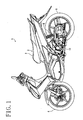
- a motorcycle shown in FIG. 1 is an example of a motorcycle 1 according to this embodiment.
- the motorcycle 1 includes a body 3 having a seat 2, a front wheel 4, a rear wheel 5 acting as a driving wheel, and a power unit 10 driving the rear wheel 5.
- the power unit 10 is a so-called unit swing type power unit.
- a front portion of the power unit 10 is supported by a pivot shaft (not shown).
- an axle 38 (see FIG. 2 ) extending in a vehicle width direction (in other words, a left/right direction) is provided.
- the rear wheel 5 is attached to the axle 38.
- a rear cushion unit 6 is provided at a substantially central position in a front/rear direction of the power unit 10.
- the power unit 10 is supported by the pivot shaft so as to be swingable around the pivot shaft with respect to the body 3, and supports the rear wheel 5 so as to be rotatable.
- the power unit 10 includes an engine (not shown) and a V-belt type variable transmission (hereinafter, referred to as "CVT" (Continuous Variable Transmission)) 20.
- the CVT 20 includes a primary sheave 21 rotatable together with a crank shaft (not shown) of the engine, a secondary sheave 22 (see FIG. 3 ), and a V-belt 23 wound around the primary sheave 21 and the secondary sheave 22.
- the CVT 20 is located leftward with respect to the engine, and is covered with a transmission case 24.
- the power unit 10 includes a crank case (not shown) for covering the engine, and the transmission case 24 is located leftward with respect to the crank case.
- the primary sheave 21 includes a primary sheave shaft 21 extending in the vehicle width direction, a movable sheave 21 a fit into the primary sheave shaft 21 c, and a fixed sheave 21 b fit into the primary sheave shaft 21 c.
- the primary sheave shaft 21 c may be connected to the crank shaft of the engine, or a part of the crank shaft may act as the primary sheave shaft 21 c.
- the movable sheave 21 a and the fixed sheave 21b face each other in the vehicle width direction.
- a belt groove is formed between the movable sheave 21 a and the fixed sheave 21 b, and the V-belt 23 is held in the belt groove.
- the movable sheave 21 a rotates together with the primary sheave shaft 21 and is movable in an axial direction thereof.
- the fixed sheave 21b rotates together with the primary sheave shaft 21c but is not movable in an axial direction thereof.
- a centrifugal weight 21d In rearward of the movable sheave 21 a, a centrifugal weight 21d is located.
- the centrifugal weight 21 d moves inward in a radial direction of the primary sheave 21 when the rotation speed of the primary sheave 21 decreases, and moves outward in the radial direction by a centrifugal force when the rotation speed of the primary sheave 21 increases.
- the movable sheave 21a is separated from the fixed sheave 21b, and thus the winding diameter of the V-belt 23 around the primary sheave 21 decreases.
- the CVT 20 is put into the state shown in FIG. 2 above the primary sheave shaft 21c.
- the transmission ratio of the CVT 20 increases.
- the centrifugal weight 21 d pushes the movable sheave 21 a toward the fixed sheave 21b, and thus the movable sheave 21a approaches the fixed sheave 21b.
- the CVT 20 is put into the state shown in FIG. 2 below the primary sheave shaft 21c.
- the winding diameter of the V-belt 23 around the primary sheave 21 increases, and the transmission ratio of the CVT 20 decreases.
- the secondary sheave 22 includes a secondary sheave shaft 22c extending in the vehicle width direction, a movable sheave fit into the secondary sheave shaft 22c, and a fixed sheave fit into the secondary sheave shaft 22c.
- the movable sheave and the fixed sheave face each other in the vehicle width direction, and a belt groove is formed therebetween.
- the movable sheave rotates together with the secondary sheave shaft 22c and is movable in an axial direction thereof.
- the fixed sheave rotates together with the secondary sheave shaft 22c but is not movable in an axial direction thereof.
- a flow path of air for cooling the CVT 20 is formed inside the transmission case 24, a flow path of air for cooling the CVT 20 is formed.
- a plurality of fins 25 is formed leftward with respect to the fixed sheave 21 b of the primary sheave 21.
- the fixed sheave 21 b is rotated to rotate the fins 25 and thus to transport the air.
- a cooling fan is formed by the fins 25.
- an intake duct 26 for introducing air from the outside of the transmission case 24 is connected to a front portion of the transmission case 24.
- the intake duct 26 has an entrance 26a opened upward and an exit 26b (see FIG. 2 ) opened rightward toward the primary sheave 21, and meanders overall.
- the transmission case 24 has an intake section 24a, for introducing air, formed leftward with respect to the fixed sheave 21b.
- the exit 26b of the intake duct 26 is connected to the intake section 24a.
- a first filter 41 is located between the exit 26b of the intake duct 26 and the intake section 24a of the transmission case 24.
- the intake duct 26 is not specifically limited to have any specific shape and does not need to meander as is in this embodiment.
- the intake duct 26 is not absolutely necessary and may be omitted.
- the air sucked into the transmission case 24 from the intake duct 26 flows around the primary sheave 21, then rearward, and around the secondary sheave 22.
- a duct 27 opened upward is formed above the secondary sheave 22.
- a gear case 30 is located rightward with respect to the transmission case 24, namely, on the vehicle center side of the transmission case 24 in the vehicle width direction.
- the gear case 30 is located adjacent to the transmission case 24 in the axial direction of the secondary sheave shaft 22c.
- the gear case 30 accommodates a first gear 31, a second gear 32, a third gear 33 and a fourth gear 34.
- the gears 31, 32, 33 and 34 transmit the rotation of the secondary sheave shaft 22c to the axle 38.
- the secondary sheave shaft 22c runs throughout the transmission case 24 in the vehicle width direction and extends into the gear case 30.
- the first gear 31 is formed at a position, in the gear case 30, corresponding to the secondary sheave shaft 22c, and rotates along with the secondary sheave shaft 22c.
- the first gear 31 may be attached to, or integrated with, the secondary sheave shaft 22c.
- the first gear 31 is engaged with the second gear 32 having a larger diameter than that of the first gear 31.
- the third gear 33 is located coaxially with the second gear 32, and rotates along with the second gear 32.
- the second gear 32 and the third gear 33 may be integral with, or separate from, each other.
- the third gear 33 is engaged with the fourth gear 34 having a larger diameter than that of the third gear 33.
- the axle 38 is fit into the center of the fourth gear 34.
- the axle 38 rotates together with the fourth gear 34.
- the rear wheel 5 is attached to the axle 38. Owing to such a structure, the rotation of the secondary sheave 22 is decelerated by the plurality of gears 31 through 34, and then is transmitted to the rear wheel 5.
- the power unit 10 includes a breather device 9 having a communication path 50.
- the inside of the gear case 30 and the inside of the transmission case 24 are communicated to each other via the communication path 50.
- the temperature inside of the gear case 30 increases and the air in the gear case 30 expands.
- the pressure inside of the gear case 30 becomes higher than the pressure outside of the gear case 30.
- the gear case 30 may be cooled down rapidly. In such a case, the air inside of the gear case 30 contracts and so the pressure inside of the gear case 30 becomes lower than the pressure outside of the gear case 30. In this manner, the pressure may be different between the inside and the outside of the gear case 30 in the power unit 10.
- the power unit 10 includes the communication path 50 for communicating the inside and the outside of the gear case 30 to each other. Therefore, when the pressure inside of the gear case 30 increases, the air inside of the gear case 30 is discharged outside through the communication path 50. By contrast, when the pressure inside of the gear case 30 decreases, air is supplied from the outside to the inside of the gear case 30 through the communication path 50. In this manner, the pressure difference between the inside and the outside of the gear case 30 is relaxed in the power unit 10 according to this embodiment.
- the communication path 50 includes a cartridge 51 fit into the gear case 30 and a hose 52 inserted into the cartridge 51.
- the cartridge 51 is formed of a synthetic resin.
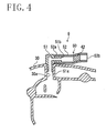
- the cartridge 51 includes an insertion joint 51a extending downward and an insertion joint 51b extending horizontally.
- the gear case 30 has a hole 30a.
- the cartridge 51 is fixed to the gear case 30 by the insertion joint 51a being inserted into the hole 30a.
- One end 52a of the hose 52 is inserted into the insertion joint 51b of the cartridge 51.
- the other end 52b of the hose 52 is opened toward the inside of the transmission case 24. Namely, the end 52b of the hose 52 is an open end.
- the hose 52 is formed of a flexible material, for example, a synthetic resin or the like. There is no specific limitation on the material of the hose 52.
- the cartridge 51 has the insertion joint 51b, and the hose 52 has the open end 52a.
- the insertion joint 51b of the cartridge 51 is inserted into the open end 52a of the hose 52.
- the end 52a of the hose 52 acts as a connection opening of the hose 52
- the insertion joint 51b of the cartridge 51 acts as a connection opening of the cartridge 51.
- the insertion joint 51b of the cartridge 51 is inserted into the end 52a of the hose 52, and thus the hose 52 and the cartridge 51 are connected to each other.
- the cartridge 51 may have a receiving joint 51d
- the hose 52 may have an insertion joint 52c which is inserted into the receiving joint 51d of the cartridge 51.
- the insertion joint 52c of the hose 52 acts as a connection opening of the hose 52
- the receiving joint 51d of the cartridge 51 acts as a connection opening of the cartridge 51.
- the gear case 30 may include a tubular member having a generally cylindrical shape.
- the tubular member is an insertion joint 30b formed on a surface of the gear case 30.
- the insertion joint 30b is formed to extend from the hole 30a to the inside and the outside of the gear case 30, and surrounds the hole 30a.
- a receiving joint 51e into which the insertion joint 30b is inserted is formed in a bottom portion of the cartridge 51.
- the cartridge 51 is fixed to the gear case 30.
- another member having a generally cylindrical shape may be inserted.
- the another member is inserted into the receiving joint 51e of the cartridge 51. Namely, the cartridge 51 may be fixed to the gear case 30 via another member.
- the communication path 50 communicates the inside of the gear case 30 and the inside of the transmission case 24 to each other.
- one end of the communication path 50 is the insertion joint 51a of the cartridge 51 attached to the gear case 30, and the other end of the communication path 50 is the open end 52b (see FIG. 4 ) of the hose 52 opened toward the inside of the transmission case 24.
- the communication path 50 is not exposed outside of the power unit 10, and so is prevented from sucking dust or the like from the outside of the power unit 10.
- a second filter 42 is provided inside the hose 52.
- the second filter 42 is formed of the same material as that of the first filter 41.
- the second filter 42 has the same degree of pore fineness as that of the first filter 41.
- the first filter 41 and the second filter 42 may be formed of different materials from each other.
- the first filter 41 and the second filter 42 may have different degrees of pore fineness from each other.
- the second filter 42 may have a higher degree of pore fineness than that of the first filter 41.
- the filter 42 is located deeper than the end 52b (i.e., the open end) of the hose 52. By locating the second filter 42 deeper in the hose 52, the filter 42 can be prevented more securely from coming off from the hose 52.
- the communication path 50 communicating the inside and the outside of the gear case 30 to each other is provided, and thus the pressure difference between the inside and the outside of the gear case 30 can be alleviated.
- the filter 42 is located inside of the communication path 50. Therefore, dust or the like, which is likely to invade the inside of the gear case 30 through the communication path 50 from the outside, is caught by the filter 42. Thus, the invasion of the dust or the like into the inside of the gear case 30 is suppressed. Accordingly, the dust or the like is suppressed from adhering to the gears 31 through 34, which protects the gears 31 through 34 against deterioration. As a result, mission noise will be suppressed from occurring and will be reduced.
- the communication path 50 includes the flexible hose 52, and the filter 42 is located inside of the hose 52.
- the communication path 50 having the filter 42 built therein can be easily realized merely by a simple operation of inserting the filter 42 into the hose 52 from the end 52b.
- the end 52b of the communication path 50 is opened toward the inside of the transmission case 24.
- the filter 41 is located on an entrance side of the transmission case 24. Therefore, the two filters 41 and 42 are located between the inside of the gear case 30 and the outside of the power unit 10. Owing to these two filters 41 and 42, dust or the like is prevented from invading the inside of the gear case 30 in a two-fold manner. Accordingly, the invasion of the dust or the like into the inside of the gear case 30 can be prevented more effectively.
- the communication path 50 is relatively short.
- the gear case 30 is located rightward with respect to the transmission case 24.
- the communication path 50 is shorter than length L, which is the length between center C1 of the primary sheave 21 and center C2 of the secondary sheave 22.
- the communication path 50 is located between a front end 22f of the secondary sheave 22 and the axle 38.
- this embodiment allows the communication path 50 to be short and compact. Since the filter 42 is located inside of the communication path 50, the invasion of dust of the like into the inside of the gear case 30 can be sufficiently suppressed even though the communication path 50 is relatively short.
- the open end 52b of the communication path 50 is located at a relatively high level.
- the open end 52b of the communication path 50 is located above line PL connecting the center C1 of the primary sheave 21 and the center C2 of the secondary sheave 22. Therefore, the communication path 50 according to this embodiment can suppress the invasion of dust or the like more than in the case where the open end 52b is located below the line PL.
- the communication path 50 is attached to the gear case 30 such that the cartridge 51 and the hose 52 are easily detached from the outside of the gear case 30.
- the cartridge 51 of the communication path 50 has a simple structure in which the insertion joint 51a is inserted into the hole 30a of the gear case 30 (see FIG. 4 ). Therefore, the cartridge 51 is easily detached from the outside of the gear case 30.
- the hose 52 and the cartridge 51 have a simple structure in which the end 52a of the hose 52 is attached to the insertion joint 51b (see FIG. 4 ) of the cartridge 51 or the receiving joint 51d (see FIG. 5 ) of the cartridge 51. This allows the hose 52 to be easily detached from the cartridge 51 or the gear case 30.
- the filter 42 provided inside of the hose 52 is easily exchangeable by a simple method of detaching the hose 52 from the cartridge 51 or the gear case 30. Namely, the power unit 10 including the breather device 9 according to this embodiment improves the ease of maintenance of the breather device 9.
- the transmission case 24, the gear case 30 and the communication path 50 are different from those of Embodiment 1.
- substantially the same elements as those of Embodiment 1 will bear the same reference numerals therewith and descriptions thereof will be omitted.
- the power unit 10 also includes the transmission case 24 and the gear case 30.
- the transmission case 24 accommodates the CVT 20.
- a plurality of gears for transmitting the rotation of the secondary sheave shaft of the CVT 20 to the axle is located in the gear case 30 as in Embodiment 1.
- a duct 28 for introducing air from above is formed in the transmission case 24.
- the intake duct 26 sucking air into the transmission case 24 is formed to guide the air to the duct 28.
- the intake duct 26 has the entrance 26a located in a front and top portion of the transmission case 24 and the generally dome-shaped exit 26b surrounding the duct 28. The air sucked from the entrance 26a flows generally rearward in the duct 28, flows upward at the exit 26b, and then flows downward to an inner portion of the duct 28.
- the first filter 41 is located inside of the exit 26b of the intake duct 26.
- the first filter 41 is generally shaped like a ring to surround the duct 28.
- the first filter 41 is not limited to being ring-shaped and may have a different shape.
- a flow path for allowing air to flow as described below is formed.
- the air introduced from the duct 28 flows around the primary sheave 21 and the secondary sheave 22, then is guided upward through a take-out duct 29, then flows downward in a rear portion of the transmission case 24, and flows out from the transmission case 24.
- the communication path 50 includes the cartridge 51 and the hose 52.
- the cartridge 51 includes the insertion joint 51a extending downward and the insertion joint 51b extending upward.
- the insertion joint 51a is inserted into the hole 30a of the gear case 30.
- One end 52a of the hose 52 is fit into the insertion joint 51b.
- an insertion joint 24d extending rightward is formed in the transmission case 24.
- the other end 52b of the hose 52 is fit into the insertion joint 24d.
- the end 52b of the hose 52 acts as an open end opened toward the inside of the transmission case 24. Owing to such a structure, the inside of the gear case 30 and the inside of the transmission case 24 are communicated to each other via the communication path 50.
- the end 52a of the hose 52 acts as a connection opening of the hose 52
- the insertion joint 51b of the cartridge 51 acts as a connection opening of the cartridge 51.
- the insertion joint 51b of the cartridge 51 is inserted into the end 52a of the hose 52, and thus the hose 52 and the cartridge 51 are connected to each other.
- the cartridge 51 of the communication path 50 may have a receiving joint 51d
- the hose 52 may have an insertion joint 52c which is inserted into the receiving joint 51d of the cartridge 51 (see FIG. 5 ).
- the transmission case 24 may have a receiving joint, extending rightward, into which the end 52b of the hose 52 is inserted.
- the gear case 30 may have a generally cylindrical insertion joint extending from the hole 30a to the inside and the outside of the gear case 30 and surrounding the hole 30a (see FIG. 6 ).
- the hose 52 is located to extend in the vehicle width direction. In other words, the hose 52 extends perpendicular to the front/rear direction of the vehicle. Therefore, the hose 52 is shorter than in Embodiment 1. The same is applied to the communication path 50. In this embodiment also, the filter 42 is located inside of the hose 52.
- the communication path 50 is formed only of the cartridge 51 described in Embodiment 1.
- the cartridge 51 has the insertion joint 51a inserted into the hole 30a of the gear case 30, but does not have any insertion joint for attaching the hose thereto.
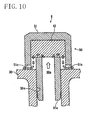
- the cartridge 51 is cap-shaped.
- a plurality of communication holes 51c running from the inside to the outside of the cartridge 51 is formed in a side surface of the cartridge 51. There is no limitation on the position or size of the communication holes 51 c.
- the inside of the transmission case 24 and the inside of the gear case 30 are communicated to each other via the cartridge 51.
- the gear case 30 has a tubular portion 30c having a generally cylindrical shape and formed to extend from the hole 30a to the inside and the outside of the gear case 30.
- the tubular portion 30c surrounds the hole 30a, and acts as a receiving joint.
- the cartridge 51 is fixed to the gear case 30 by the insertion joint 51a being inserted into the tubular portion 30c.
- the tubular portion 30a does not need to be integral with the gear case 30. More specifically, another member having a generally cylindrical shape may be inserted into the hole 30a of the gear case 30, and the communication path 50 may be formed of the another member and the cartridge 51.
- the tubular portion 30c having the generally cylindrical shape acts as a connection opening
- the insertion joint 51a of the cartridge 51 acts as a connection opening of the cartridge 51.
- the insertion joint 51a of the cartridge 51 is inserted into the tubular portion 30c, and thus the cartridge 51 and the tubular portion 30c are connected to each other.
- the gear case 30 may have a tubular portion 30f formed therein.
- the tubular portion 30f is formed to extend from the hole 30a to the inside and the outside of the gear case 30.
- the tubular portion 30f surrounds the hole 30a, and acts as an insertion joint.
- the cartridge 51 has a receiving joint 51f into which the tubular portion 30f is inserted, but does not have any insertion joint or receiving joint for attaching the hose thereto.
- the cartridge 51 is fixed to the gear case 30 by the tubular portion 30f being inserted into the receiving joint 51f.
- the tubular portion 30f having a generally cylindrical shape acts as a connection opening
- the receiving joint 51f of the cartridge 51 acts as a connection opening of the cartridge 51.
- the tubular portion 30f is inserted into the receiving joint 5 1 f of the cartridge 51, and thus the cartridge 51 and the tubular portion 30f are connected to each other.
- the tubular portion 30f does not need to be integral with the gear case 30, and another member having a generally cylindrical shape may be inserted into the hole 30a of the gear case 30. As shown in FIG. 11B , the tubular portion 30f may have a plurality of claws 39. In the case where the tubular portion 30f has the plurality of claws 39 and a plurality of gaps, each of the gaps being formed between each adjacent two claws among the plurality of claws 39, it is easier to attach or detach the cartridge 51 and the cartridge 51 is fixed to the tubular portion 30f more securely.
- the second filter 42 is accommodated inside of the cartridge 51.
- the second filter 42 is built in the cartridge 51 beforehand.
- the arrows indicate the flow of air from the inside to the outside of the gear case 30.
- the filter 42 prevents the invasion of dust or the like from the outside of the gear case 30.
- the second filter 42 is located between the communication holes 51 c and the insertion joint 51a in the cartridge 51. In other words, the second filter 42 is located between the communication holes 51c and the insertion joint 51a of the cartridge 51 in the communication path 50.
- the second filter 42 is located between the communication holes 51c and the receiving joint 51d in the cartridge 51. In other words, the second filter 42 is located between the communication holes 51c and the tubular portion 30f in the communication path 50.
- the same effects as those of Embodiments 1 and 2 are provided.
- the hose 52 is unnecessary. Therefore, the number of elements can be reduced.
- the communication path 50 can be still shorter and still more compact.
- the power unit 10 may occasionally vibrate and the hose 52 may also vibrate while the motorcycle 1 is in motion.
- the power unit 10 does not include the hose 52 and so such a vibration of the hose 52 does not occur. For this reason, the durability and the reliability of the communication path 50 can be further improved.
- the power unit 10 in each of the above-described embodiments is a so-called unit swing type power unit, which is supported so as to be swingable with respect to the body 3.
- a power unit according to the present invention may be supported so as not to swingable with respect to the body.
- gears located in the gear case 30 there is no limitation on the type or number of the gears located in the gear case 30. There is no limitation on the shape of the gears.
- a motorcycle according to the present invention may be of a moped type, a scooter type or any other type.
Landscapes
- Engineering & Computer Science (AREA)
- General Engineering & Computer Science (AREA)
- Mechanical Engineering (AREA)
- General Details Of Gearings (AREA)
Abstract
Description
- The present invention relates to a power unit, for a motorcycle, including a breather device, and a motorcycle including the same.
- A power unit including a breather device is conventionally known as described in, for example,
Patent Document 1 specified below. This power unit includes a case accommodating gears and a breather device having a communication path communicating the inside and the outside of the case to each other. Through the communication path, air can be guided from the inside to the outside of the case, and from the outside to the inside of the case. -
- Patent document 1: Japanese Laid-Open Utility Model Publication for Opposition No.
59-25748 - The present inventor found a novel problem that in a power unit, for a motorcycle, including a case accommodating gears and a breather device having a communication path communicating the inside and the outside of the case to each other, unusual noise (hereinafter, referred to as "mission noise") may be occur from the inside of the case after the power unit is used for a long time.
- The present invention made in light of such circumstances has an object of reducing mission noise in a power unit, for a motorcycle, including a breather device.
- As a result of active studies, the present inventor obtained the knowledge that dust or the like invades the inside of the case from the outside through the breather device and abrades the gears in the case, and as a result, mission noise occurs. Based on this knowledge, the present inventor took the following means.
- A power unit for a motorcycle according to the present invention includes a belt type variable transmission including a primary sheave rotating based on driving of an engine of the motorcycle, a secondary sheave, a V-belt wound around the primary sheave and the secondary sheave, and a secondary sheave shaft rotating together with the secondary sheave; a plurality of gears located between the secondary sheave shaft and an axle of a driving wheel of the motorcycle and transmitting a torque of the secondary sheave shaft to the axle; a gear case accommodating the plurality of gears; and a breather device including a communication path communicating the inside and the outside of the gear case. The communication path includes a first member having a connection opening of either an inserting type or an inserted type; and a second member which is at least partially located outside of the gear case and has a connection opening, of either an inserting type or an inserted type, connected with the connection opening of the first member. The second member accommodates a filter.
- According to the above-described power unit, dust or the like which enters the communication path from the outside of the case is caught by the filter. Therefore, the dust or the like is suppressed from invading the inside of the case, and is prevented from adhering to the gears. For this reason, the power unit, for a motorcycle, including a breather device according to the present invention suppresses the abrasion of the gears, and so the mission noise can be reduced.
- The present invention will reduce mission noise in a power unit, for a motorcycle, including a breather device.
-
- [
FIG. 1] FIG. 1 is a left side view of a motorcycle. - [
FIG. 2] FIG. 2 is a partial plan view of a power unit according toEmbodiment 1, in which a part of the power unit is cut out. - [
FIG. 3] FIG. 3 is a left side view of the power unit according to Embodiment 1. - [
FIG. 4] FIG. 4 is a cross-sectional view showing a structure of a breather device according toEmbodiment 1. - [
FIG. 5] FIG. 5 is a cross-sectional view showing a structure of the breather device according toEmbodiment 1. - [
FIG. 6] FIG. 6 is a cross-sectional view showing a part of a structure of the breather device according toEmbodiment 1. - [
FIG. 7] FIG. 7 is a partial plan view of a power unit according to Embodiment 2, in which a part of the power unit is cut out. - [
FIG. 8] FIG. 8 is a left side view of the power unit according to Embodiment 2. - [
FIG. 9] FIG. 9 is a cross-sectional view taken along line A-A inFIG 7 , showing a structure of a breather device according to Embodiment 2. - [
FIG. 10] FIG. 10 is a cross-sectional view showing a structure of a breather device according to Embodiment 3. - [
FIG. 11] FIG. 11 provides cross-sectional views each showing a structure of the breather device according to Embodiment 3. - A motorcycle shown in
FIG. 1 is an example of amotorcycle 1 according to this embodiment. Themotorcycle 1 includes a body 3 having a seat 2, a front wheel 4, arear wheel 5 acting as a driving wheel, and apower unit 10 driving therear wheel 5. Thepower unit 10 is a so-called unit swing type power unit. A front portion of thepower unit 10 is supported by a pivot shaft (not shown). In a rear portion of thepower unit 10, an axle 38 (seeFIG. 2 ) extending in a vehicle width direction (in other words, a left/right direction) is provided. Therear wheel 5 is attached to theaxle 38. At a substantially central position in a front/rear direction of thepower unit 10, arear cushion unit 6 is provided. Owing to such a structure, thepower unit 10 is supported by the pivot shaft so as to be swingable around the pivot shaft with respect to the body 3, and supports therear wheel 5 so as to be rotatable. - As shown in
FIG. 2 , thepower unit 10 includes an engine (not shown) and a V-belt type variable transmission (hereinafter, referred to as "CVT" (Continuous Variable Transmission)) 20. As shown inFIG. 2 , the CVT 20 includes aprimary sheave 21 rotatable together with a crank shaft (not shown) of the engine, a secondary sheave 22 (seeFIG. 3 ), and a V-belt 23 wound around theprimary sheave 21 and thesecondary sheave 22. The CVT 20 is located leftward with respect to the engine, and is covered with atransmission case 24. Thepower unit 10 includes a crank case (not shown) for covering the engine, and thetransmission case 24 is located leftward with respect to the crank case. - The
primary sheave 21 includes aprimary sheave shaft 21 extending in the vehicle width direction, amovable sheave 21 a fit into theprimary sheave shaft 21 c, and afixed sheave 21 b fit into theprimary sheave shaft 21 c. Theprimary sheave shaft 21 c may be connected to the crank shaft of the engine, or a part of the crank shaft may act as theprimary sheave shaft 21 c. Themovable sheave 21 a and thefixed sheave 21b face each other in the vehicle width direction. A belt groove is formed between themovable sheave 21 a and thefixed sheave 21 b, and the V-belt 23 is held in the belt groove. Themovable sheave 21 a rotates together with theprimary sheave shaft 21 and is movable in an axial direction thereof. By contrast, thefixed sheave 21b rotates together with theprimary sheave shaft 21c but is not movable in an axial direction thereof. - In rearward of the
movable sheave 21 a, acentrifugal weight 21d is located. Thecentrifugal weight 21 d moves inward in a radial direction of theprimary sheave 21 when the rotation speed of theprimary sheave 21 decreases, and moves outward in the radial direction by a centrifugal force when the rotation speed of theprimary sheave 21 increases. Owing to this, when the rotation speed of theprimary sheave 21 decreases, themovable sheave 21a is separated from the fixedsheave 21b, and thus the winding diameter of the V-belt 23 around theprimary sheave 21 decreases. Namely, the CVT 20 is put into the state shown inFIG. 2 above theprimary sheave shaft 21c. As a result, the transmission ratio of theCVT 20 increases. By contrast, when the rotation speed of theprimary sheave 21 increases, thecentrifugal weight 21 d pushes themovable sheave 21 a toward thefixed sheave 21b, and thus themovable sheave 21a approaches thefixed sheave 21b. Namely, the CVT 20 is put into the state shown inFIG. 2 below theprimary sheave shaft 21c. As a result, the winding diameter of the V-belt 23 around theprimary sheave 21 increases, and the transmission ratio of theCVT 20 decreases. - Although partially omitted in the figure, the
secondary sheave 22 includes asecondary sheave shaft 22c extending in the vehicle width direction, a movable sheave fit into thesecondary sheave shaft 22c, and a fixed sheave fit into thesecondary sheave shaft 22c. The movable sheave and the fixed sheave face each other in the vehicle width direction, and a belt groove is formed therebetween. The movable sheave rotates together with thesecondary sheave shaft 22c and is movable in an axial direction thereof. By contrast, the fixed sheave rotates together with thesecondary sheave shaft 22c but is not movable in an axial direction thereof. - Inside the
transmission case 24, a flow path of air for cooling theCVT 20 is formed. As shown inFIG. 2 , a plurality offins 25 is formed leftward with respect to the fixedsheave 21 b of theprimary sheave 21. The fixedsheave 21 b is rotated to rotate thefins 25 and thus to transport the air. In other words, a cooling fan is formed by thefins 25. As shown inFIG. 3 , anintake duct 26 for introducing air from the outside of thetransmission case 24 is connected to a front portion of thetransmission case 24. Theintake duct 26 has anentrance 26a opened upward and anexit 26b (seeFIG. 2 ) opened rightward toward theprimary sheave 21, and meanders overall. Thetransmission case 24 has anintake section 24a, for introducing air, formed leftward with respect to the fixedsheave 21b. Theexit 26b of theintake duct 26 is connected to theintake section 24a. Afirst filter 41 is located between theexit 26b of theintake duct 26 and theintake section 24a of thetransmission case 24. Theintake duct 26 is not specifically limited to have any specific shape and does not need to meander as is in this embodiment. Theintake duct 26 is not absolutely necessary and may be omitted. - As shown in
FIG. 2 andFIG. 3 with arrows, the air sucked into thetransmission case 24 from theintake duct 26 flows around theprimary sheave 21, then rearward, and around thesecondary sheave 22. Above thesecondary sheave 22, aduct 27 opened upward is formed. The air, which has flown around thesecondary sheave 22, flows upward through theduct 27, then flows downward in a rear portion of thetransmission case 24, and flows out from thetransmission case 24. - As shown in
FIG. 2 , agear case 30 is located rightward with respect to thetransmission case 24, namely, on the vehicle center side of thetransmission case 24 in the vehicle width direction. In other words, thegear case 30 is located adjacent to thetransmission case 24 in the axial direction of thesecondary sheave shaft 22c. - As shown in
FIG. 3 , thegear case 30 accommodates afirst gear 31, asecond gear 32, a third gear 33 and afourth gear 34. Thegears secondary sheave shaft 22c to theaxle 38. Thesecondary sheave shaft 22c runs throughout thetransmission case 24 in the vehicle width direction and extends into thegear case 30. Thefirst gear 31 is formed at a position, in thegear case 30, corresponding to thesecondary sheave shaft 22c, and rotates along with thesecondary sheave shaft 22c. Thefirst gear 31 may be attached to, or integrated with, thesecondary sheave shaft 22c. Thefirst gear 31 is engaged with thesecond gear 32 having a larger diameter than that of thefirst gear 31. The third gear 33 is located coaxially with thesecond gear 32, and rotates along with thesecond gear 32. Thesecond gear 32 and the third gear 33 may be integral with, or separate from, each other. The third gear 33 is engaged with thefourth gear 34 having a larger diameter than that of the third gear 33. Into the center of thefourth gear 34, theaxle 38 is fit. Theaxle 38 rotates together with thefourth gear 34. As described above, therear wheel 5 is attached to theaxle 38. Owing to such a structure, the rotation of thesecondary sheave 22 is decelerated by the plurality ofgears 31 through 34, and then is transmitted to therear wheel 5. - The
power unit 10 according to this embodiment includes abreather device 9 having acommunication path 50. The inside of thegear case 30 and the inside of thetransmission case 24 are communicated to each other via thecommunication path 50. While thepower unit 10 is being driven, the temperature inside of thegear case 30 increases and the air in thegear case 30 expands. As a result, the pressure inside of thegear case 30 becomes higher than the pressure outside of thegear case 30. By contrast, after the engine of thepower unit 10 is stopped, the temperature inside of thegear unit 30 decreases. In the case where themotorcycle 1 runs on a puddle or the like, thegear case 30 may be cooled down rapidly. In such a case, the air inside of thegear case 30 contracts and so the pressure inside of thegear case 30 becomes lower than the pressure outside of thegear case 30. In this manner, the pressure may be different between the inside and the outside of thegear case 30 in thepower unit 10. - However, the
power unit 10 according to this embodiment includes thecommunication path 50 for communicating the inside and the outside of thegear case 30 to each other. Therefore, when the pressure inside of thegear case 30 increases, the air inside of thegear case 30 is discharged outside through thecommunication path 50. By contrast, when the pressure inside of thegear case 30 decreases, air is supplied from the outside to the inside of thegear case 30 through thecommunication path 50. In this manner, the pressure difference between the inside and the outside of thegear case 30 is relaxed in thepower unit 10 according to this embodiment. - In this embodiment, the
communication path 50 includes acartridge 51 fit into thegear case 30 and ahose 52 inserted into thecartridge 51. Thecartridge 51 is formed of a synthetic resin. As shown inFIG. 4 , thecartridge 51 includes an insertion joint 51a extending downward and an insertion joint 51b extending horizontally. Thegear case 30 has ahole 30a. Thecartridge 51 is fixed to thegear case 30 by the insertion joint 51a being inserted into thehole 30a. Oneend 52a of thehose 52 is inserted into the insertion joint 51b of thecartridge 51. Theother end 52b of thehose 52 is opened toward the inside of thetransmission case 24. Namely, theend 52b of thehose 52 is an open end. Thehose 52 is formed of a flexible material, for example, a synthetic resin or the like. There is no specific limitation on the material of thehose 52. - As described above, the
cartridge 51 has the insertion joint 51b, and thehose 52 has theopen end 52a. Into theopen end 52a of thehose 52, the insertion joint 51b of thecartridge 51 is inserted. In this embodiment, theend 52a of thehose 52 acts as a connection opening of thehose 52, and the insertion joint 51b of thecartridge 51 acts as a connection opening of thecartridge 51. The insertion joint 51b of thecartridge 51 is inserted into theend 52a of thehose 52, and thus thehose 52 and thecartridge 51 are connected to each other. Alternatively, as shown inFIG. 5 , thecartridge 51 may have a receiving joint 51d, and thehose 52 may have an insertion joint 52c which is inserted into the receiving joint 51d of thecartridge 51. In this case, the insertion joint 52c of thehose 52 acts as a connection opening of thehose 52, and the receiving joint 51d of thecartridge 51 acts as a connection opening of thecartridge 51. - As shown in
FIG. 6 , thegear case 30 may include a tubular member having a generally cylindrical shape. In this embodiment, the tubular member is an insertion joint 30b formed on a surface of thegear case 30. The insertion joint 30b is formed to extend from thehole 30a to the inside and the outside of thegear case 30, and surrounds thehole 30a. In this case, a receiving joint 51e into which the insertion joint 30b is inserted is formed in a bottom portion of thecartridge 51. Owing to such a structure, thecartridge 51 is fixed to thegear case 30. Into thehole 30a, another member having a generally cylindrical shape may be inserted. In this case, the another member is inserted into the receiving joint 51e of thecartridge 51. Namely, thecartridge 51 may be fixed to thegear case 30 via another member. - As shown in
FIG. 2 , thecommunication path 50 communicates the inside of thegear case 30 and the inside of thetransmission case 24 to each other. In this embodiment, one end of thecommunication path 50 is the insertion joint 51a of thecartridge 51 attached to thegear case 30, and the other end of thecommunication path 50 is theopen end 52b (seeFIG. 4 ) of thehose 52 opened toward the inside of thetransmission case 24. Thus, thecommunication path 50 is not exposed outside of thepower unit 10, and so is prevented from sucking dust or the like from the outside of thepower unit 10. - Inside the
hose 52, asecond filter 42 is provided. In this embodiment, thesecond filter 42 is formed of the same material as that of thefirst filter 41. Thesecond filter 42 has the same degree of pore fineness as that of thefirst filter 41. Thefirst filter 41 and thesecond filter 42 may be formed of different materials from each other. Thefirst filter 41 and thesecond filter 42 may have different degrees of pore fineness from each other. For example, thesecond filter 42 may have a higher degree of pore fineness than that of thefirst filter 41. - There is no specific limitation on the position of the
filter 42 in thehose 42. In this embodiment, thefilter 42 is located deeper than theend 52b (i.e., the open end) of thehose 52. By locating thesecond filter 42 deeper in thehose 52, thefilter 42 can be prevented more securely from coming off from thehose 52. - As described above, according to this embodiment, the
communication path 50 communicating the inside and the outside of thegear case 30 to each other is provided, and thus the pressure difference between the inside and the outside of thegear case 30 can be alleviated. In addition, thefilter 42 is located inside of thecommunication path 50. Therefore, dust or the like, which is likely to invade the inside of thegear case 30 through thecommunication path 50 from the outside, is caught by thefilter 42. Thus, the invasion of the dust or the like into the inside of thegear case 30 is suppressed. Accordingly, the dust or the like is suppressed from adhering to thegears 31 through 34, which protects thegears 31 through 34 against deterioration. As a result, mission noise will be suppressed from occurring and will be reduced. - The
communication path 50 includes theflexible hose 52, and thefilter 42 is located inside of thehose 52. Thecommunication path 50 having thefilter 42 built therein can be easily realized merely by a simple operation of inserting thefilter 42 into thehose 52 from theend 52b. - According to this embodiment, the
end 52b of thecommunication path 50 is opened toward the inside of thetransmission case 24. Thefilter 41 is located on an entrance side of thetransmission case 24. Therefore, the twofilters gear case 30 and the outside of thepower unit 10. Owing to these twofilters gear case 30 in a two-fold manner. Accordingly, the invasion of the dust or the like into the inside of thegear case 30 can be prevented more effectively. - Also according to this embodiment, the
communication path 50 is relatively short. Specifically, thegear case 30 is located rightward with respect to thetransmission case 24. As shown inFIG. 3 , as seen from the side (in other words, as seen in the axial direction of thesecondary sheave shaft 22c), thecommunication path 50 is shorter than length L, which is the length between center C1 of theprimary sheave 21 and center C2 of thesecondary sheave 22. In addition, thecommunication path 50 is located between afront end 22f of thesecondary sheave 22 and theaxle 38. In order to suppress the invasion of dust or the like into the inside of thegear case 30, it is conceivable to make thecommunication path 50 longer. On the contrary, this embodiment allows thecommunication path 50 to be short and compact. Since thefilter 42 is located inside of thecommunication path 50, the invasion of dust of the like into the inside of thegear case 30 can be sufficiently suppressed even though thecommunication path 50 is relatively short. - According to this embodiment, the
open end 52b of thecommunication path 50 is located at a relatively high level. In more detail, theopen end 52b of thecommunication path 50 is located above line PL connecting the center C1 of theprimary sheave 21 and the center C2 of thesecondary sheave 22. Therefore, thecommunication path 50 according to this embodiment can suppress the invasion of dust or the like more than in the case where theopen end 52b is located below the line PL. - In this embodiment, the
communication path 50 is attached to thegear case 30 such that thecartridge 51 and thehose 52 are easily detached from the outside of thegear case 30. For example, thecartridge 51 of thecommunication path 50 has a simple structure in which the insertion joint 51a is inserted into thehole 30a of the gear case 30 (seeFIG. 4 ). Therefore, thecartridge 51 is easily detached from the outside of thegear case 30. Thehose 52 and thecartridge 51 have a simple structure in which theend 52a of thehose 52 is attached to the insertion joint 51b (seeFIG. 4 ) of thecartridge 51 or the receiving joint 51d (seeFIG. 5 ) of thecartridge 51. This allows thehose 52 to be easily detached from thecartridge 51 or thegear case 30. Thefilter 42 provided inside of thehose 52 is easily exchangeable by a simple method of detaching thehose 52 from thecartridge 51 or thegear case 30. Namely, thepower unit 10 including thebreather device 9 according to this embodiment improves the ease of maintenance of thebreather device 9. - In a
power unit 10 according to Embodiment 2, thetransmission case 24, thegear case 30 and thecommunication path 50 are different from those ofEmbodiment 1. In the following description, substantially the same elements as those ofEmbodiment 1 will bear the same reference numerals therewith and descriptions thereof will be omitted. - As shown in
FIG. 7 , thepower unit 10 according to this embodiment also includes thetransmission case 24 and thegear case 30. Thetransmission case 24 accommodates theCVT 20. Although not shown, a plurality of gears for transmitting the rotation of the secondary sheave shaft of theCVT 20 to the axle is located in thegear case 30 as inEmbodiment 1. - In this embodiment, as shown in
FIG. 8 , aduct 28 for introducing air from above is formed in thetransmission case 24. Theintake duct 26 sucking air into thetransmission case 24 is formed to guide the air to theduct 28. Theintake duct 26 has theentrance 26a located in a front and top portion of thetransmission case 24 and the generally dome-shapedexit 26b surrounding theduct 28. The air sucked from theentrance 26a flows generally rearward in theduct 28, flows upward at theexit 26b, and then flows downward to an inner portion of theduct 28. - In this embodiment, the
first filter 41 is located inside of theexit 26b of theintake duct 26. Thefirst filter 41 is generally shaped like a ring to surround theduct 28. Thefirst filter 41 is not limited to being ring-shaped and may have a different shape. - In the
transmission case 24, a flow path for allowing air to flow as described below is formed. The air introduced from theduct 28 flows around theprimary sheave 21 and thesecondary sheave 22, then is guided upward through a take-outduct 29, then flows downward in a rear portion of thetransmission case 24, and flows out from thetransmission case 24. - As shown in
FIG. 9 , in this embodiment also, thecommunication path 50 includes thecartridge 51 and thehose 52. In this embodiment, thecartridge 51 includes the insertion joint 51a extending downward and the insertion joint 51b extending upward. The insertion joint 51a is inserted into thehole 30a of thegear case 30. Oneend 52a of thehose 52 is fit into the insertion joint 51b. In this embodiment, an insertion joint 24d extending rightward is formed in thetransmission case 24. Theother end 52b of thehose 52 is fit into the insertion joint 24d. In this embodiment also, theend 52b of thehose 52 acts as an open end opened toward the inside of thetransmission case 24. Owing to such a structure, the inside of thegear case 30 and the inside of thetransmission case 24 are communicated to each other via thecommunication path 50. - In this embodiment also, the
end 52a of thehose 52 acts as a connection opening of thehose 52, and the insertion joint 51b of thecartridge 51 acts as a connection opening of thecartridge 51. The insertion joint 51b of thecartridge 51 is inserted into theend 52a of thehose 52, and thus thehose 52 and thecartridge 51 are connected to each other. As inEmbodiment 1, thecartridge 51 of thecommunication path 50 may have a receiving joint 51d, and thehose 52 may have an insertion joint 52c which is inserted into the receiving joint 51d of the cartridge 51 (seeFIG. 5 ). Although not shown, thetransmission case 24 may have a receiving joint, extending rightward, into which theend 52b of thehose 52 is inserted. Thegear case 30 may have a generally cylindrical insertion joint extending from thehole 30a to the inside and the outside of thegear case 30 and surrounding thehole 30a (seeFIG. 6 ). - As shown in
FIG. 7 , in this embodiment, thehose 52 is located to extend in the vehicle width direction. In other words, thehose 52 extends perpendicular to the front/rear direction of the vehicle. Therefore, thehose 52 is shorter than inEmbodiment 1. The same is applied to thecommunication path 50. In this embodiment also, thefilter 42 is located inside of thehose 52. - In this embodiment also, the same effects as those of
Embodiment 1 are provided. - In a
power unit 10 according to Embodiment 3, thecommunication path 50 is formed only of thecartridge 51 described inEmbodiment 1. As shown inFIG. 10 , in Embodiment 3, thecartridge 51 has the insertion joint 51a inserted into thehole 30a of thegear case 30, but does not have any insertion joint for attaching the hose thereto. Thecartridge 51 is cap-shaped. A plurality ofcommunication holes 51c running from the inside to the outside of thecartridge 51 is formed in a side surface of thecartridge 51. There is no limitation on the position or size of the communication holes 51 c. The inside of thetransmission case 24 and the inside of thegear case 30 are communicated to each other via thecartridge 51. - As shown in
FIG. 10 , thegear case 30 has atubular portion 30c having a generally cylindrical shape and formed to extend from thehole 30a to the inside and the outside of thegear case 30. Thus, thetubular portion 30c surrounds thehole 30a, and acts as a receiving joint. Thecartridge 51 is fixed to thegear case 30 by the insertion joint 51a being inserted into thetubular portion 30c. Thetubular portion 30a does not need to be integral with thegear case 30. More specifically, another member having a generally cylindrical shape may be inserted into thehole 30a of thegear case 30, and thecommunication path 50 may be formed of the another member and thecartridge 51. - In this embodiment, the
tubular portion 30c having the generally cylindrical shape acts as a connection opening, and the insertion joint 51a of thecartridge 51 acts as a connection opening of thecartridge 51. The insertion joint 51a of thecartridge 51 is inserted into thetubular portion 30c, and thus thecartridge 51 and thetubular portion 30c are connected to each other. - As shown in
FIG. 11A and FIG. 11B , thegear case 30 may have atubular portion 30f formed therein. Thetubular portion 30f is formed to extend from thehole 30a to the inside and the outside of thegear case 30. Thus, thetubular portion 30f surrounds thehole 30a, and acts as an insertion joint. In this case, thecartridge 51 has a receiving joint 51f into which thetubular portion 30f is inserted, but does not have any insertion joint or receiving joint for attaching the hose thereto. Thecartridge 51 is fixed to thegear case 30 by thetubular portion 30f being inserted into the receiving joint 51f. In thebreather device 9 shown in each ofFIG. 11A and FIG. 11B , thetubular portion 30f having a generally cylindrical shape acts as a connection opening, and the receiving joint 51f of thecartridge 51 acts as a connection opening of thecartridge 51. Thetubular portion 30f is inserted into the receiving joint 51f of thecartridge 51, and thus thecartridge 51 and thetubular portion 30f are connected to each other. - The
tubular portion 30f does not need to be integral with thegear case 30, and another member having a generally cylindrical shape may be inserted into thehole 30a of thegear case 30. As shown inFIG. 11B , thetubular portion 30f may have a plurality ofclaws 39. In the case where thetubular portion 30f has the plurality ofclaws 39 and a plurality of gaps, each of the gaps being formed between each adjacent two claws among the plurality ofclaws 39, it is easier to attach or detach thecartridge 51 and thecartridge 51 is fixed to thetubular portion 30f more securely. - In this embodiment, the
second filter 42 is accommodated inside of thecartridge 51. Namely, thesecond filter 42 is built in thecartridge 51 beforehand. InFIG. 10 ,FIG. 11A and FIG. 11B , the arrows indicate the flow of air from the inside to the outside of thegear case 30. In this embodiment also, thefilter 42 prevents the invasion of dust or the like from the outside of thegear case 30. - In
FIG. 10 , thesecond filter 42 is located between the communication holes 51 c and the insertion joint 51a in thecartridge 51. In other words, thesecond filter 42 is located between the communication holes 51c and the insertion joint 51a of thecartridge 51 in thecommunication path 50. By contrast, inFIG. 11A and FIG. 11B , thesecond filter 42 is located between the communication holes 51c and the receiving joint 51d in thecartridge 51. In other words, thesecond filter 42 is located between the communication holes 51c and thetubular portion 30f in thecommunication path 50. - In this embodiment also, the same effects as those of
Embodiments 1 and 2 are provided. In addition, in this embodiment, unlike inEmbodiments 1 and 2, thehose 52 is unnecessary. Therefore, the number of elements can be reduced. Thecommunication path 50 can be still shorter and still more compact. In the case where thepower unit 10 includes thehose 52, thepower unit 10 may occasionally vibrate and thehose 52 may also vibrate while themotorcycle 1 is in motion. However, in this embodiment, thepower unit 10 does not include thehose 52 and so such a vibration of thehose 52 does not occur. For this reason, the durability and the reliability of thecommunication path 50 can be further improved. - The
power unit 10 in each of the above-described embodiments is a so-called unit swing type power unit, which is supported so as to be swingable with respect to the body 3. A power unit according to the present invention may be supported so as not to swingable with respect to the body. - There is no limitation on the type or number of the gears located in the
gear case 30. There is no limitation on the shape of the gears. - A motorcycle according to the present invention may be of a moped type, a scooter type or any other type.
-
- 1
- Motorcycle
- 5
- Rear wheel (driving wheel)
- 9
- Breather device
- 10
- Power unit
- 20
- Belt type variable transmission
- 21
- Primary sheave
- 22
- Secondary sheave
- 22c
- Secondary sheave shaft
- 22f
- Front end of the secondary sheave
- 23
- V-belt
- 24
- Transmission case
- 26a
- Entrance
- 30
- Gear case
- 30a
- Hole
- 30c
- Tubular portion (tubular member) (first member) (connection opening)
- 30f
- Tubular portion (tubular member) (first member) (connection opening)
- 31, 32, 33, 34
- Gear
- 38
- Axle
- 41
- Filter (another filter)
- 42
- Filter
- 50
- Communication path
- 51
- Cartridge (first member) (second member)
- 51a
- (Connection opening of the second member) insertion joint
- 51b
- (Connection opening of the first member) insertion joint
- 51c
- Communication hole
- 51d
- (Connection opening of the first member) receiving joint
- 51f
- (Connection opening of the second member) receiving joint
- 52
- Hose (second member)
- 52a
- (Connection opening of the second member) receiving joint
- 52b
- Open end
- 52c
- (Connection opening of the second member) insertion joint
-
C 1 - Center of the primary sheave
- C2
- Center of the secondary sheave
Claims (9)
- A power unit for a motorcycle, comprising:a belt type variable transmission including a primary sheave rotating based on driving of an engine of the motorcycle, a secondary sheave, a V-belt wound around the primary sheave and the secondary sheave, and a secondary sheave shaft rotating together with the secondary sheave;a plurality of gears located between the secondary sheave shaft and an axle of a driving wheel of the motorcycle and transmitting a torque of the secondary sheave shaft to the axle;a gear case accommodating the plurality of gears; anda breather device including a communication path communicating the inside and the outside of the gear case;the communication path includes:a first member having a connection opening of either an inserting type or an inserted type; anda second member which is at least partially located outside of the gear case and has a connection opening, of either an inserting type or an inserted type, connected with the connection opening of the first member; andthe second member accommodates a filter.
- A power unit according to claim 1, wherein:the second member is a flexible hose; andthe filter is inserted into the hose.
- A power unit according to claim 1, wherein:a hole is formed in the gear case;the first member is a tubular member surrounding the hole, the tubular member being formed in a direction extending to the inside and the outside of the gear case from the hole;the second member further includes a communication hole and is fixed to the gear case by the connection opening thereof being connected to the tubular member; andthe filter is located between the connection opening and the communication hole in the second member.
- A power unit according to claim 1, further comprising a transmission case accommodating the belt type variable transmission; wherein the communication path communicates the inside of the gear case and the inside of the transmission case to each other.
- A power unit according to claim 4, wherein:the transmission case has an entrance for introducing air; andthe power unit further includes another filter different from the filter, the another filter being located downstream with respect to the entrance and upstream with respect to the communication path.
- A power unit according to claim 4, wherein:the gear case is located adjacent to the transmission case in an axial direction of the secondary sheave shaft; andthe communication path is shorter than a length between a center of the primary sheave and a center of the secondary sheave as seen in the axial direction of the secondary sheave shaft.
- A power unit according to claim 4, wherein:the communication path has an open end opened toward the inside of the transmission case; andthe open end is located above a line connecting a center of the primary sheave and a center of the secondary sheave as seen in an axial direction of the secondary sheave shaft.
- A power unit according to claim 1, wherein:where, in a direction in which a line connecting a center of the primary sheave and a center of the secondary sheave extends, the primary sheave is located on a front side and the secondary sheave is located on a rear side, the axle is located rearward with respect to the center of the secondary sheave as seen in an axial direction of the secondary sheave shaft; andthe communication path is located between a front end of the secondary sheave and the axle as seen in the axial direction of the secondary sheave shaft.
- A motorcycle, comprising a power unit for a motorcycle according to claim 1.
Applications Claiming Priority (2)
| Application Number | Priority Date | Filing Date | Title |
|---|---|---|---|
| JP2008127316 | 2008-05-14 | ||
| PCT/JP2009/056973 WO2009139234A1 (en) | 2008-05-14 | 2009-04-03 | Power unit adapted for use in two-wheeled motor vehicle and having breather device, and two-wheeled motor vehicle with the same |
Publications (3)
| Publication Number | Publication Date |
|---|---|
| EP2287031A1 true EP2287031A1 (en) | 2011-02-23 |
| EP2287031A4 EP2287031A4 (en) | 2011-09-21 |
| EP2287031B1 EP2287031B1 (en) | 2012-11-21 |
Family
ID=41318607
Family Applications (1)
| Application Number | Title | Priority Date | Filing Date |
|---|---|---|---|
| EP09746441A Active EP2287031B1 (en) | 2008-05-14 | 2009-04-03 | Power unit adapted for use in two-wheeled motor vehicle and having breather device, and two-wheeled motor vehicle with the same |
Country Status (3)
| Country | Link |
|---|---|
| EP (1) | EP2287031B1 (en) |
| ES (1) | ES2399209T3 (en) |
| WO (1) | WO2009139234A1 (en) |
Cited By (4)
| Publication number | Priority date | Publication date | Assignee | Title |
|---|---|---|---|---|
| EP2765071A1 (en) * | 2013-02-07 | 2014-08-13 | Yamaha Motor Co., Ltd. | Straddle-type vehicle with air-cooled transmission |
| KR101467125B1 (en) * | 2013-12-27 | 2014-11-28 | 현대다이모스(주) | Radiating air breather device |
| WO2019105918A1 (en) * | 2017-11-30 | 2019-06-06 | Getrag Ford Transmissions Gmbh | Transmission with a separate breather element |
| FR3089269A1 (en) * | 2018-12-04 | 2020-06-05 | Suzuki Motor Corporation | Breather structure |
Families Citing this family (7)
| Publication number | Priority date | Publication date | Assignee | Title |
|---|---|---|---|---|
| DE102010036294A1 (en) * | 2010-09-03 | 2012-03-08 | Hydac Filtertechnik Gmbh | System for ventilation of containers of fluid volume |
| EP2644494A4 (en) * | 2010-11-22 | 2015-01-07 | Yamaha Motor Co Ltd | Power unit for saddled electric vehicle, and saddled electric vehicle |
| JP5914317B2 (en) * | 2012-12-21 | 2016-05-11 | 本田技研工業株式会社 | Air cleaner case structure for saddle riding type vehicles |
| JP6541319B2 (en) * | 2014-09-19 | 2019-07-10 | Ntn株式会社 | Breather structure of in-wheel motor drive |
| DE112017008228B4 (en) * | 2017-11-22 | 2024-10-10 | Honda Motor Co., Ltd. | MOTOR-INTEGRATED TRANSMISSION DEVICE |
| CN112770969B (en) * | 2018-09-27 | 2022-08-23 | 本田技研工业株式会社 | Electric vehicle |
| JP7216129B2 (en) * | 2021-02-22 | 2023-01-31 | 本田技研工業株式会社 | straddle-type vehicle |
Family Cites Families (9)
| Publication number | Priority date | Publication date | Assignee | Title |
|---|---|---|---|---|
| JPS5925748U (en) | 1982-08-10 | 1984-02-17 | 株式会社中北製作所 | Control valve |
| JPH0735850B2 (en) * | 1985-11-25 | 1995-04-19 | スズキ株式会社 | Breather device |
| JPH0272848U (en) * | 1988-11-24 | 1990-06-04 | ||
| JP3486507B2 (en) * | 1996-08-28 | 2004-01-13 | Nok株式会社 | Breather with adapter |
| US6015444A (en) * | 1998-02-27 | 2000-01-18 | Eaton Corporation | Apparatus and system for venting a transmission |
| JP3916376B2 (en) * | 2000-06-15 | 2007-05-16 | 本田技研工業株式会社 | Breather structure of internal combustion engine for vehicle |
| US6447565B1 (en) * | 2001-05-03 | 2002-09-10 | General Motors Corporation | Transmission vent assembly |
| JP4198925B2 (en) * | 2002-03-15 | 2008-12-17 | 日産ディーゼル工業株式会社 | Breather structure for vehicle gearbox |
| JP2007064425A (en) * | 2005-09-01 | 2007-03-15 | Toyota Motor Corp | Breather plug |
-
2009
- 2009-04-03 WO PCT/JP2009/056973 patent/WO2009139234A1/en not_active Ceased
- 2009-04-03 EP EP09746441A patent/EP2287031B1/en active Active
- 2009-04-03 ES ES09746441T patent/ES2399209T3/en active Active
Cited By (6)
| Publication number | Priority date | Publication date | Assignee | Title |
|---|---|---|---|---|
| EP2765071A1 (en) * | 2013-02-07 | 2014-08-13 | Yamaha Motor Co., Ltd. | Straddle-type vehicle with air-cooled transmission |
| KR101467125B1 (en) * | 2013-12-27 | 2014-11-28 | 현대다이모스(주) | Radiating air breather device |
| WO2019105918A1 (en) * | 2017-11-30 | 2019-06-06 | Getrag Ford Transmissions Gmbh | Transmission with a separate breather element |
| CN111512066A (en) * | 2017-11-30 | 2020-08-07 | 各特拉格·福特传动系统公司 | Transmission with split exhaust element |
| US11067161B2 (en) | 2017-11-30 | 2021-07-20 | Getrag Ford Transmissions Gmbh | Transmission with a separate breather element |
| FR3089269A1 (en) * | 2018-12-04 | 2020-06-05 | Suzuki Motor Corporation | Breather structure |
Also Published As
| Publication number | Publication date |
|---|---|
| EP2287031A4 (en) | 2011-09-21 |
| ES2399209T3 (en) | 2013-03-26 |
| WO2009139234A1 (en) | 2009-11-19 |
| EP2287031B1 (en) | 2012-11-21 |
Similar Documents
| Publication | Publication Date | Title |
|---|---|---|
| EP2287031B1 (en) | Power unit adapted for use in two-wheeled motor vehicle and having breather device, and two-wheeled motor vehicle with the same | |
| US10995843B2 (en) | Work vehicle | |
| US8911312B2 (en) | Belt type continuously variable transmission | |
| US20130090199A1 (en) | Belt Type Continuously Variable Transmisson | |
| ES2327459T3 (en) | ENGINE. | |
| JP6076978B2 (en) | Turbocharged engine | |
| US7647995B2 (en) | Riding type vehicle | |
| EP2650568B1 (en) | Gear box and saddle-type vehicle including the same | |
| US8656885B2 (en) | Engine for a vehicle | |
| US7343833B2 (en) | Breather apparatus of crankcase | |
| US11047272B2 (en) | Engine lubrication system, engine, and vehicle | |
| US20120247875A1 (en) | Lubrication structure for engine | |
| EP3306138A1 (en) | Belt type stepless transmission | |
| EP2295833A1 (en) | Engine unit, and a two-wheeled motor vehicle having the same | |
| JP2017194146A (en) | Cooling device of transmission | |
| JP4291859B2 (en) | engine | |
| KR101717574B1 (en) | Lubricant structure for reduction gear of electric four wheel drive vehicle | |
| JP2002206604A (en) | V-belt type automatic transmission | |
| EP3333460B1 (en) | Oil discharge structure of rotational body | |
| EP3032143B1 (en) | Transfer case and motorcycle having the same | |
| EP1798395B1 (en) | Vehicle transmission | |
| US20090294241A1 (en) | Lubricant discharging mechanism of clutch apparatus for transmission | |
| JP2004052908A (en) | Power unit for vehicle | |
| EP1580113B1 (en) | Power transmission device and traveling vehicle | |
| JP2025148915A (en) | Work vehicle |
Legal Events
| Date | Code | Title | Description |
|---|---|---|---|
| PUAI | Public reference made under article 153(3) epc to a published international application that has entered the european phase |
Free format text: ORIGINAL CODE: 0009012 |
|
| 17P | Request for examination filed |
Effective date: 20101105 |
|
| AK | Designated contracting states |
Kind code of ref document: A1 Designated state(s): AT BE BG CH CY CZ DE DK EE ES FI FR GB GR HR HU IE IS IT LI LT LU LV MC MK MT NL NO PL PT RO SE SI SK TR |
|
| AX | Request for extension of the european patent |
Extension state: AL BA RS |
|
| RIC1 | Information provided on ipc code assigned before grant |
Ipc: F16H 9/18 20060101ALN20110629BHEP Ipc: B62M 9/08 20060101AFI20110629BHEP Ipc: B62M 11/02 20060101ALI20110629BHEP Ipc: F16H 57/02 20060101ALI20110629BHEP |
|
| DAX | Request for extension of the european patent (deleted) | ||
| A4 | Supplementary search report drawn up and despatched |
Effective date: 20110823 |
|
| RIC1 | Information provided on ipc code assigned before grant |
Ipc: F16H 9/18 20060101ALN20110817BHEP Ipc: B62M 11/02 20060101ALI20110817BHEP Ipc: B62M 9/08 20060101AFI20110817BHEP Ipc: F16H 57/02 20060101ALI20110817BHEP |
|
| REG | Reference to a national code |
Ref country code: DE Ref legal event code: R079 Ref document number: 602009011385 Country of ref document: DE Free format text: PREVIOUS MAIN CLASS: B60K0017060000 Ipc: B62M0009080000 |
|
| GRAP | Despatch of communication of intention to grant a patent |
Free format text: ORIGINAL CODE: EPIDOSNIGR1 |
|
| RIC1 | Information provided on ipc code assigned before grant |
Ipc: B62M 9/08 20060101AFI20120425BHEP Ipc: F16H 57/027 20120101ALI20120425BHEP Ipc: F16H 9/18 20060101ALN20120425BHEP Ipc: B62M 11/02 20060101ALI20120425BHEP |
|
| GRAS | Grant fee paid |
Free format text: ORIGINAL CODE: EPIDOSNIGR3 |
|
| GRAA | (expected) grant |
Free format text: ORIGINAL CODE: 0009210 |
|
| AK | Designated contracting states |
Kind code of ref document: B1 Designated state(s): AT BE BG CH CY CZ DE DK EE ES FI FR GB GR HR HU IE IS IT LI LT LU LV MC MK MT NL NO PL PT RO SE SI SK TR |
|
| REG | Reference to a national code |
Ref country code: GB Ref legal event code: FG4D |
|
| REG | Reference to a national code |
Ref country code: CH Ref legal event code: EP |
|
| REG | Reference to a national code |
Ref country code: AT Ref legal event code: REF Ref document number: 584920 Country of ref document: AT Kind code of ref document: T Effective date: 20121215 |
|
| REG | Reference to a national code |
Ref country code: IE Ref legal event code: FG4D |
|
| REG | Reference to a national code |
Ref country code: DE Ref legal event code: R096 Ref document number: 602009011385 Country of ref document: DE Effective date: 20130117 |
|
| REG | Reference to a national code |
Ref country code: ES Ref legal event code: FG2A Ref document number: 2399209 Country of ref document: ES Kind code of ref document: T3 Effective date: 20130326 |
|
| REG | Reference to a national code |
Ref country code: NL Ref legal event code: VDEP Effective date: 20121121 |
|
| REG | Reference to a national code |
Ref country code: AT Ref legal event code: MK05 Ref document number: 584920 Country of ref document: AT Kind code of ref document: T Effective date: 20121121 |
|
| REG | Reference to a national code |
Ref country code: LT Ref legal event code: MG4D |
|
| PG25 | Lapsed in a contracting state [announced via postgrant information from national office to epo] |
Ref country code: LT Free format text: LAPSE BECAUSE OF FAILURE TO SUBMIT A TRANSLATION OF THE DESCRIPTION OR TO PAY THE FEE WITHIN THE PRESCRIBED TIME-LIMIT Effective date: 20121121 Ref country code: HR Free format text: LAPSE BECAUSE OF FAILURE TO SUBMIT A TRANSLATION OF THE DESCRIPTION OR TO PAY THE FEE WITHIN THE PRESCRIBED TIME-LIMIT Effective date: 20121121 Ref country code: NO Free format text: LAPSE BECAUSE OF FAILURE TO SUBMIT A TRANSLATION OF THE DESCRIPTION OR TO PAY THE FEE WITHIN THE PRESCRIBED TIME-LIMIT Effective date: 20130221 Ref country code: FI Free format text: LAPSE BECAUSE OF FAILURE TO SUBMIT A TRANSLATION OF THE DESCRIPTION OR TO PAY THE FEE WITHIN THE PRESCRIBED TIME-LIMIT Effective date: 20121121 Ref country code: SE Free format text: LAPSE BECAUSE OF FAILURE TO SUBMIT A TRANSLATION OF THE DESCRIPTION OR TO PAY THE FEE WITHIN THE PRESCRIBED TIME-LIMIT Effective date: 20121121 |
|
| PG25 | Lapsed in a contracting state [announced via postgrant information from national office to epo] |
Ref country code: GR Free format text: LAPSE BECAUSE OF FAILURE TO SUBMIT A TRANSLATION OF THE DESCRIPTION OR TO PAY THE FEE WITHIN THE PRESCRIBED TIME-LIMIT Effective date: 20130222 Ref country code: SI Free format text: LAPSE BECAUSE OF FAILURE TO SUBMIT A TRANSLATION OF THE DESCRIPTION OR TO PAY THE FEE WITHIN THE PRESCRIBED TIME-LIMIT Effective date: 20121121 Ref country code: LV Free format text: LAPSE BECAUSE OF FAILURE TO SUBMIT A TRANSLATION OF THE DESCRIPTION OR TO PAY THE FEE WITHIN THE PRESCRIBED TIME-LIMIT Effective date: 20121121 Ref country code: BE Free format text: LAPSE BECAUSE OF FAILURE TO SUBMIT A TRANSLATION OF THE DESCRIPTION OR TO PAY THE FEE WITHIN THE PRESCRIBED TIME-LIMIT Effective date: 20121121 Ref country code: PL Free format text: LAPSE BECAUSE OF FAILURE TO SUBMIT A TRANSLATION OF THE DESCRIPTION OR TO PAY THE FEE WITHIN THE PRESCRIBED TIME-LIMIT Effective date: 20121121 Ref country code: PT Free format text: LAPSE BECAUSE OF FAILURE TO SUBMIT A TRANSLATION OF THE DESCRIPTION OR TO PAY THE FEE WITHIN THE PRESCRIBED TIME-LIMIT Effective date: 20130321 |
|
| PG25 | Lapsed in a contracting state [announced via postgrant information from national office to epo] |
Ref country code: AT Free format text: LAPSE BECAUSE OF FAILURE TO SUBMIT A TRANSLATION OF THE DESCRIPTION OR TO PAY THE FEE WITHIN THE PRESCRIBED TIME-LIMIT Effective date: 20121121 |
|
| PG25 | Lapsed in a contracting state [announced via postgrant information from national office to epo] |
Ref country code: EE Free format text: LAPSE BECAUSE OF FAILURE TO SUBMIT A TRANSLATION OF THE DESCRIPTION OR TO PAY THE FEE WITHIN THE PRESCRIBED TIME-LIMIT Effective date: 20121121 Ref country code: SK Free format text: LAPSE BECAUSE OF FAILURE TO SUBMIT A TRANSLATION OF THE DESCRIPTION OR TO PAY THE FEE WITHIN THE PRESCRIBED TIME-LIMIT Effective date: 20121121 Ref country code: CZ Free format text: LAPSE BECAUSE OF FAILURE TO SUBMIT A TRANSLATION OF THE DESCRIPTION OR TO PAY THE FEE WITHIN THE PRESCRIBED TIME-LIMIT Effective date: 20121121 Ref country code: BG Free format text: LAPSE BECAUSE OF FAILURE TO SUBMIT A TRANSLATION OF THE DESCRIPTION OR TO PAY THE FEE WITHIN THE PRESCRIBED TIME-LIMIT Effective date: 20130221 Ref country code: DK Free format text: LAPSE BECAUSE OF FAILURE TO SUBMIT A TRANSLATION OF THE DESCRIPTION OR TO PAY THE FEE WITHIN THE PRESCRIBED TIME-LIMIT Effective date: 20121121 |
|
| PG25 | Lapsed in a contracting state [announced via postgrant information from national office to epo] |
Ref country code: RO Free format text: LAPSE BECAUSE OF FAILURE TO SUBMIT A TRANSLATION OF THE DESCRIPTION OR TO PAY THE FEE WITHIN THE PRESCRIBED TIME-LIMIT Effective date: 20121121 Ref country code: NL Free format text: LAPSE BECAUSE OF FAILURE TO SUBMIT A TRANSLATION OF THE DESCRIPTION OR TO PAY THE FEE WITHIN THE PRESCRIBED TIME-LIMIT Effective date: 20121121 |
|
| PLBE | No opposition filed within time limit |
Free format text: ORIGINAL CODE: 0009261 |
|
| STAA | Information on the status of an ep patent application or granted ep patent |
Free format text: STATUS: NO OPPOSITION FILED WITHIN TIME LIMIT |
|
| 26N | No opposition filed |
Effective date: 20130822 |
|
| REG | Reference to a national code |
Ref country code: DE Ref legal event code: R119 Ref document number: 602009011385 Country of ref document: DE |
|
| PG25 | Lapsed in a contracting state [announced via postgrant information from national office to epo] |
Ref country code: MC Free format text: LAPSE BECAUSE OF FAILURE TO SUBMIT A TRANSLATION OF THE DESCRIPTION OR TO PAY THE FEE WITHIN THE PRESCRIBED TIME-LIMIT Effective date: 20121121 |
|
| REG | Reference to a national code |
Ref country code: CH Ref legal event code: PL |
|
| REG | Reference to a national code |
Ref country code: DE Ref legal event code: R097 Ref document number: 602009011385 Country of ref document: DE Effective date: 20130822 |
|
| GBPC | Gb: european patent ceased through non-payment of renewal fee |
Effective date: 20130403 |
|
| REG | Reference to a national code |
Ref country code: IE Ref legal event code: MM4A |
|
| PG25 | Lapsed in a contracting state [announced via postgrant information from national office to epo] |
Ref country code: GB Free format text: LAPSE BECAUSE OF NON-PAYMENT OF DUE FEES Effective date: 20130403 Ref country code: CH Free format text: LAPSE BECAUSE OF NON-PAYMENT OF DUE FEES Effective date: 20130430 Ref country code: DE Free format text: LAPSE BECAUSE OF NON-PAYMENT OF DUE FEES Effective date: 20131101 Ref country code: LI Free format text: LAPSE BECAUSE OF NON-PAYMENT OF DUE FEES Effective date: 20130430 |
|
| REG | Reference to a national code |
Ref country code: DE Ref legal event code: R119 Ref document number: 602009011385 Country of ref document: DE Effective date: 20131101 |
|
| PG25 | Lapsed in a contracting state [announced via postgrant information from national office to epo] |
Ref country code: IE Free format text: LAPSE BECAUSE OF NON-PAYMENT OF DUE FEES Effective date: 20130403 |
|
| PG25 | Lapsed in a contracting state [announced via postgrant information from national office to epo] |
Ref country code: MT Free format text: LAPSE BECAUSE OF FAILURE TO SUBMIT A TRANSLATION OF THE DESCRIPTION OR TO PAY THE FEE WITHIN THE PRESCRIBED TIME-LIMIT Effective date: 20121121 |
|
| PG25 | Lapsed in a contracting state [announced via postgrant information from national office to epo] |
Ref country code: CY Free format text: LAPSE BECAUSE OF FAILURE TO SUBMIT A TRANSLATION OF THE DESCRIPTION OR TO PAY THE FEE WITHIN THE PRESCRIBED TIME-LIMIT Effective date: 20121121 |
|
| PG25 | Lapsed in a contracting state [announced via postgrant information from national office to epo] |
Ref country code: LU Free format text: LAPSE BECAUSE OF NON-PAYMENT OF DUE FEES Effective date: 20130403 Ref country code: HU Free format text: LAPSE BECAUSE OF FAILURE TO SUBMIT A TRANSLATION OF THE DESCRIPTION OR TO PAY THE FEE WITHIN THE PRESCRIBED TIME-LIMIT; INVALID AB INITIO Effective date: 20090403 Ref country code: MK Free format text: LAPSE BECAUSE OF FAILURE TO SUBMIT A TRANSLATION OF THE DESCRIPTION OR TO PAY THE FEE WITHIN THE PRESCRIBED TIME-LIMIT Effective date: 20121121 |
|
| REG | Reference to a national code |
Ref country code: FR Ref legal event code: PLFP Year of fee payment: 8 |
|
| PG25 | Lapsed in a contracting state [announced via postgrant information from national office to epo] |
Ref country code: IS Free format text: LAPSE BECAUSE OF FAILURE TO SUBMIT A TRANSLATION OF THE DESCRIPTION OR TO PAY THE FEE WITHIN THE PRESCRIBED TIME-LIMIT Effective date: 20121121 |
|
| REG | Reference to a national code |
Ref country code: FR Ref legal event code: PLFP Year of fee payment: 9 |
|
| REG | Reference to a national code |
Ref country code: FR Ref legal event code: PLFP Year of fee payment: 10 |
|
| P01 | Opt-out of the competence of the unified patent court (upc) registered |
Effective date: 20230527 |
|
| PGFP | Annual fee paid to national office [announced via postgrant information from national office to epo] |
Ref country code: ES Payment date: 20250529 Year of fee payment: 17 |
|
| PGFP | Annual fee paid to national office [announced via postgrant information from national office to epo] |
Ref country code: IT Payment date: 20250424 Year of fee payment: 17 |
|
| PGFP | Annual fee paid to national office [announced via postgrant information from national office to epo] |
Ref country code: FR Payment date: 20250424 Year of fee payment: 17 |
|
| PGFP | Annual fee paid to national office [announced via postgrant information from national office to epo] |
Ref country code: TR Payment date: 20260331 Year of fee payment: 18 |