EP2286990B1 - Method to separate an adhesive material from a releasable substrate using an impact - Google Patents
Method to separate an adhesive material from a releasable substrate using an impact Download PDFInfo
- Publication number
- EP2286990B1 EP2286990B1 EP20090010675 EP09010675A EP2286990B1 EP 2286990 B1 EP2286990 B1 EP 2286990B1 EP 20090010675 EP20090010675 EP 20090010675 EP 09010675 A EP09010675 A EP 09010675A EP 2286990 B1 EP2286990 B1 EP 2286990B1
- Authority
- EP
- European Patent Office
- Prior art keywords
- adhesive material
- release liner
- releasable substrate
- adhesive
- impact
- Prior art date
- Legal status (The legal status is an assumption and is not a legal conclusion. Google has not performed a legal analysis and makes no representation as to the accuracy of the status listed.)
- Not-in-force
Links
- 239000000463 material Substances 0.000 title claims 26
- 239000000853 adhesive Substances 0.000 title claims 25
- 230000001070 adhesive effect Effects 0.000 title claims 25
- 239000000758 substrate Substances 0.000 title claims 15
- 238000000034 method Methods 0.000 title claims 10
- 239000012790 adhesive layer Substances 0.000 claims 1
- 230000005285 magnetism related processes and functions Effects 0.000 claims 1
- 238000010297 mechanical methods and process Methods 0.000 claims 1
- 230000005226 mechanical processes and functions Effects 0.000 claims 1
Images
Classifications
-
- B—PERFORMING OPERATIONS; TRANSPORTING
- B32—LAYERED PRODUCTS
- B32B—LAYERED PRODUCTS, i.e. PRODUCTS BUILT-UP OF STRATA OF FLAT OR NON-FLAT, e.g. CELLULAR OR HONEYCOMB, FORM
- B32B43/00—Operations specially adapted for layered products and not otherwise provided for, e.g. repairing; Apparatus therefor
- B32B43/006—Delaminating
-
- B—PERFORMING OPERATIONS; TRANSPORTING
- B32—LAYERED PRODUCTS
- B32B—LAYERED PRODUCTS, i.e. PRODUCTS BUILT-UP OF STRATA OF FLAT OR NON-FLAT, e.g. CELLULAR OR HONEYCOMB, FORM
- B32B38/00—Ancillary operations in connection with laminating processes
- B32B38/18—Handling of layers or the laminate
- B32B2038/1891—Using a robot for handling the layers
-
- B—PERFORMING OPERATIONS; TRANSPORTING
- B32—LAYERED PRODUCTS
- B32B—LAYERED PRODUCTS, i.e. PRODUCTS BUILT-UP OF STRATA OF FLAT OR NON-FLAT, e.g. CELLULAR OR HONEYCOMB, FORM
- B32B2310/00—Treatment by energy or chemical effects
- B32B2310/04—Treatment by energy or chemical effects using liquids, gas or steam
- B32B2310/0445—Treatment by energy or chemical effects using liquids, gas or steam using gas or flames
- B32B2310/0454—Hot air
-
- B—PERFORMING OPERATIONS; TRANSPORTING
- B32—LAYERED PRODUCTS
- B32B—LAYERED PRODUCTS, i.e. PRODUCTS BUILT-UP OF STRATA OF FLAT OR NON-FLAT, e.g. CELLULAR OR HONEYCOMB, FORM
- B32B38/00—Ancillary operations in connection with laminating processes
- B32B38/18—Handling of layers or the laminate
- B32B38/1858—Handling of layers or the laminate using vacuum
Definitions
- the present invention relates to a method to separate an adhesive material from a releasable substrate attached to the adhesive material by fixing the releasable substrate with respect to the adhesive material and peeling off the substrate from the adhesive material, as well as a release apparatus for separating a releasable substrate from an adhesive material.
- Adhesive components are widespreadly used in industry and private applications having various designs, assemblies and materials.
- a complete adhesive component comprises a backing, such as a plastic film, a fabric, a damping material, a mold component etc., one or more adhesive layers superposed on the backing and a releasable liner or backing material for the protection of the adhesive surface superposed on the outer sticky surface of the adhesive layers.
- a releasable liner protects the application side of the adhesive layers prior to the application of the adhesive component, but can be easily removed from the adhesive layers prior to the application without providing any damages or degeneracy to the adhesive.
- the problems and defects related with the peeling of a release liner from the sticky surface of a respective adhesive component depend on the visco-elastic properties of the adhesive material.
- visco-elastic materials Unlike pure elastic substrates such as rubber, visco-elastic materials have an elastic part and a viscous part.
- the viscosity of a visco-elastic material provides a strain rate dependent on time, i.e. if a force is held constant, the strain increases with time.
- the release liner is peeled off fast from the surface of the adhesive material.
- the cohesion within the adhesive material is larger than the adhesion between the sticky surface of the adhesive material and the surface of a release liner, wherein the adhesion is dependent on the surface properties of a release liner and the adhesion properties of the sticky surface of the adhesive material.
- the cohesion is larger than the adhesion it occurs only an elastic behavior within the adhesive material, resulting in an accurate separation of the release liner and the adhesive material at their interface.
- adhesive components such as trim panels or damping materials are widespreadly used to cover hard surfaces of car interiors and to reduce noise emissions. Due to the long term use of such adhesive components and vibration stress during operation time, the sticky surface of adhesive materials in general have a high adhesion property. Due to the high requirements for components used for automotive applications, the adhesive material often consists of a butyl rubber-based adhesive to which a backing layer (e.g., constraint film or a molded trim part panel) is attached, while the opposed sticky adhesive side is covered with a release liner.
- a backing layer e.g., constraint film or a molded trim part panel
- the application process can be performed fully automated at automotive plants using robots that pick up the individual pieces, remove the release liner and place the adhesive panels to their position.
- the peeling of the release liner from the adhesive surface is performed uniformly and at a high velocity, which in general reduces the problems occurring during the peeling off the release liner.
- the adhesive material of the trim and damping panels especially if butyl rubber-based adhesive is used, softens and starts bleeding, which increases the adhesion of the bond especially at the side wall of the adhesive material layers i.e. in a region where the peeling off starts.
- the e-module of the adhesive material is somewhat lower. Due to the increased adhesion and the reduced cohesion at higher temperatures, the peeling of the release liner more often results in the stretching and/or elongation of the adhesive material, which might cause application failures.
- This problem is solved by a generic process in that, after fixing the releasable substrate with respect to the adhesive material, an impact is provided to the releasable substrate and/or the adhesive material to at least reduce adhesion between the releasable substrate and the adhesive material in a predetermined area prior to peeling of the substrate from the adhesive material.
- the impact provided to the releasable substrate and/or the adhesive material induces a short-term, high-impulse force to the releasable substrate, which may be specified as a short time, high shock on the bond between the releasable substrate and the adhesive material. Due to the short-term impulse the removal process between the releasable substrate and the sticky material is performed in a different frequency area than in a normal process for peeling of a substrate.
- the adhesive material especially if butyl rubber based adhesives are used, reacting to such a temporary shock much more within its elastic behavior, as within the short time this high impact force is applied to the component only a small viscous reaction is possible.
- the removal process of the releasable substrate can continue in a common way without any problem.
- the impact force and the impact time strongly depend on the viscous-elastic properties of the adhesive material or the adhesive layers. Furthermore, for a good response of the adhesive material to the short-term high force shock, the impact is directed to the portion of the releasable substrate and/or the adhesive material that is fixed with respect to each other.
- the preferred solution for providing an impact to the releasable substrate and/or the sticky material is an air pulse.
- This air pulse may be generated by an air nozzle placed above the adhesive component, but having no contact to the adhesive component.
- Such an air pulse provides a high force impulse to the releasable substrate without any contact to the adhesive material and/or releasable substrate and thus generating a contact-free initial loosening of the releasable substrate.
- a mechanical impulse to the releasable substrate and/or the sticky material having a direct contact to the component.
- a mechanical kick may be controlled by a pneumatic, electrical, magnetic or mechanical actuator. Due to the direct contact, a respective contacting tip can be designed with respect to the required impact force and impact time , i.e. adapted to the visco-elastic properties of the different adhesive material. Furthermore, the direct contact and use of a respective tip allows a well-directed orientation and pointing of the impact.
- the releasable substrate is a release liner or backing material attached to the sticky surface of the adhesive material, while the adhesive material comprises one or more adhesive layers with or without a backing.
- fixing means are used for fixing the releasable substrate with respect to adhesive material such as suction caps or clamps, which are commonly used with robots for automated fabrication.
- adhesive material such as suction caps or clamps, which are commonly used with robots for automated fabrication.
- At least one suction cup can be attached to the adhesive material so that a robot for fully automated production can pick up the individual components.
- a clamp may be attached to the releasable substrate for easy fixing the substrate with respect to the sticky material, wherein the releasable substrate can be peeled off by moving the at least one suction cap with respect to the clamp.
- the impact is directed to an area of the releasable substrate and/or the adhesive material located between the at least one suction cap attached to the adhesive material and the clamp attached to the releasable substrate.
- the short term shock of the impact is positioned within an area in that the releasable substrate is clearly fixed with respect to the sticky material avoiding dissipation of the impact force.
- the suction cap attached to the adhesive material and the clamp attached to the releasable substrate for fixing the releasable substrate with respect to the adhesive material are preferably moved relative to each other for peeling off the substrate from the adhesive material, so that the peeling off starts in the vicinity of the predetermined area having an at least reduced adhesion between the releasable substrate and the adhesive material due to the impact.
- the present invention is further directed to a release apparatus for separating a release liner from an adhesive material comprising fixing means for fixing the adhesive material and fixing means for fixing the release liner with respect to the adhesive material and for peeling off a release liner from the adhesive material and further comprising an impact unit providing a force impact to the release liner and/or the adhesive material to at least reduce adhesion between the release liner and the adhesive material in a predetermined area prior to the peeling off the release liner.
- the release apparatus of the present invention allows a safe and easy removal of the release liner from an adhesive component such as adhesive trim panels or damping panels.
- the force impact provided by the impact unit to the release liner and/or the adhesive material provides a reduction of the adhesion between the release liner and the adhesive surface of the adhesive material in a predetermined area prior to the peeling of the release liner.
- the reduction of the adhesion leads to an initial loosening of the release liner from the sticky surface or to a breaking of the bond at the interface between the release liner and the adhesive material.
- the removal process of the release liner can be performed in a normal fashion, even though the ambient conditions of the release apparatus commonly would lead to problems with the peeling of the release liner if a normal removing process without an impact is used.
- the use of a release apparatus according to the present invention allows the removal of the release liner from trim panels or damping materials without any application failures, even though in high summer temperature conditions, the cohesion of the adhesive material is low due to a lower e-module of the adhesive and the adhesion at the interface of release liner and adhesive surface is high due to a more soft adhesive material and a possible bleeding of the adhesive material.
- the impact unit for providing a force impact to an adhesive component i.e. an adhesive material with or without a backing and a release liner attached to the sticky surface of the adhesive material
- an adhesive component i.e. an adhesive material with or without a backing and a release liner attached to the sticky surface of the adhesive material
- the impact unit can be designed as an air nozzle providing a strong air pulse to the adhesive component for high-speed shock treatment of the release liner.
- a further possible solution for the impact unit is a mechanical pulse unit which is controlled by a pneumatic, electrical, magnetic or mechanical process.
- a mechanical kick to the adhesive component by the mechanical pulse unit also may provides a high-speed shock treatment of the release liner to generate an initial loosening of the liner.
- the force impact to the release liner and/or the adhesive material providing a high-speed shock interaction between the release liner and the adhesive material leading to an initial reaction in a high frequency area at the interface thereof resulting in a loosening of the release liner, as the force impact is responded within in the elastic mode of the adhesive material.
- the fixing means for fixing the adhesive material is at least one suction cap positioned on the surface of the adhesive material opposite the release liner.
- Suction caps for fixing the adhesive material allow transformation of the release apparatus to a robot for automated fabrication.
- the fixing means for fixing the release liner is a clamp positioned on a portion of the release liner exceeding the adhesive material. The fixing of the release liner on a portion exceeding the adhesive material allows the fixing of the release liner for the impact to the release liner and/or the adhesive material and further directly allows the subsequent peeling of the release liner form the adhesive material.
- the release apparatus of Figure 1 is designed as a robot to pick up the adhesive component 1, wherein only the relevant components of the robot are shown.
- the adhesive component 1 is to be attached by adhesion to a greater workpiece.
- the adhesive component 1 consists of an adhesive material 2 and a release liner 3.
- the adhesive material 2 comprises an adhesive layer 2a with or without a backing 26, such as a plastic film, a fabric, a damping material or a mold component, or the adhesive material 2 comprises stacks of adhesive layers 2a with or without backing 2b.
- the release liner 3 is attached to the adhesive material 2, wherein the release liner 3 is held in position by the adhesion of the sticky surface of the adhesive material 2.
- the adhesive component 1 is held by suction heads 4, placed on the backing surface 5 of the adhesive component 1.
- the suction heads 4 and the adhesive component attached thereto are attached to and moved by the robot (not shown) via the robot arms 6.
- a clamp 7 attached and moved by the robot via a further robot arm 6, having upper and lower gripper for fixing the release liner 3 at a portion laterally exceeding the adhesive material 2.
- an air nozzle 8 is positioned directed to the laterally exceeding portion of the release liner 3.
- any other position of the air nozzle 8, above the backing surface of the adhesive material 2, and from the downside of the adhesive component 1, the side of the release liner 3, is possible.
- the air nozzle 8 provides an air pulse 9 to the portion of the release liner 3 exceeding laterally the adhesive material 2.
- the air pulse 9 providing an impact to the release liner 3.
- the air pulse 9 and the related impact to the release liner and/or the adhesive material can also be directed to the adhesive material 2 or the downside of the release liner 3.
- the air pulse 9 applying a short-term high-impact force on the release liner 3, that can be regarded as a shock to the adhesive component 1.
- the short-term high-force shock results in a removal process of the release liner 3, that is happening in a different frequency area than in a normal peeling off process.
- the adhesive reacts only in its elastic mold, so that merely the whole force impact of the air pulse 9 is directed to the adhesive connection between the release liner 3 and the adhesive material 2.
- the high frequency shock breaks the connection between the release liner 3 and the adhesive material 2 at least in a predetermined area, preferably in the vicinity of the portion of the release liner 3 where the peeling off starts.
- the release liner 3 can be peeled off the sticky surface of the adhesive material 2 by a normal peel-off movement 10 of the adhesive material 2 fixed by the suction heads 4 with respect to the release liner 3 fixed to clamp 7.
- the peel off movement 10 first moves the adhesive material 2 via the robot arm 6 in direction to the clamp 7 holding the release liner 3 and then moves upwards and backwards, wherein the backward movement increases with the length of the release liner 3 peeled of the adhesive material 2.
- the removal process of the release liner 3 is performed without any problems, even if the ambient temperatures are high and the bond between the adhesive material 2 and the release liner 3 is increased due to bleeding of the adhesive.
- the peel off movement 10 is performed resulting in a complete removal of a release liner 3, the adhesive material is attached with its sticky surface to a greater workpiece by the related robot.
Landscapes
- Adhesives Or Adhesive Processes (AREA)
Description
- The present invention relates to a method to separate an adhesive material from a releasable substrate attached to the adhesive material by fixing the releasable substrate with respect to the adhesive material and peeling off the substrate from the adhesive material, as well as a release apparatus for separating a releasable substrate from an adhesive material.
- Adhesive components are widespreadly used in industry and private applications having various designs, assemblies and materials. In general, a complete adhesive component comprises a backing, such as a plastic film, a fabric, a damping material, a mold component etc., one or more adhesive layers superposed on the backing and a releasable liner or backing material for the protection of the adhesive surface superposed on the outer sticky surface of the adhesive layers. Such a releasable liner protects the application side of the adhesive layers prior to the application of the adhesive component, but can be easily removed from the adhesive layers prior to the application without providing any damages or degeneracy to the adhesive.
- The problems and defects related with the peeling of a release liner from the sticky surface of a respective adhesive component depend on the visco-elastic properties of the adhesive material. Unlike pure elastic substrates such as rubber, visco-elastic materials have an elastic part and a viscous part. The viscosity of a visco-elastic material provides a strain rate dependent on time, i.e. if a force is held constant, the strain increases with time. Thus, to avoid or reduce a viscous behavior of the adhesive material, the release liner is peeled off fast from the surface of the adhesive material. When removing the release liner fast relative to the sticky surface of the adhesive material, in general the cohesion within the adhesive material is larger than the adhesion between the sticky surface of the adhesive material and the surface of a release liner, wherein the adhesion is dependent on the surface properties of a release liner and the adhesion properties of the sticky surface of the adhesive material. As far as the cohesion is larger than the adhesion it occurs only an elastic behavior within the adhesive material, resulting in an accurate separation of the release liner and the adhesive material at their interface. When the adhesion is larger than the cohesion, for instance due to a slow peeling off the release liner, a viscous behavior of the adhesive material occurs resulting in stretching and/or elongation of the adhesive material, while the adhesive material keeps sticking to the liner.
- Within the automotive industry, adhesive components such as trim panels or damping materials are widespreadly used to cover hard surfaces of car interiors and to reduce noise emissions. Due to the long term use of such adhesive components and vibration stress during operation time, the sticky surface of adhesive materials in general have a high adhesion property. Due to the high requirements for components used for automotive applications, the adhesive material often consists of a butyl rubber-based adhesive to which a backing layer (e.g., constraint film or a molded trim part panel) is attached, while the opposed sticky adhesive side is covered with a release liner.
- In order to reduce application costs for adhesive trim panels or damping panels, the application process can be performed fully automated at automotive plants using robots that pick up the individual pieces, remove the release liner and place the adhesive panels to their position. To the automated process, the peeling of the release liner from the adhesive surface is performed uniformly and at a high velocity, which in general reduces the problems occurring during the peeling off the release liner. However, mostly in summer when temperature conditions in automotive factories are rather high, the adhesive material of the trim and damping panels, especially if butyl rubber-based adhesive is used, softens and starts bleeding, which increases the adhesion of the bond especially at the side wall of the adhesive material layers i.e. in a region where the peeling off starts. Furthermore, because of the higher temperature, the e-module of the adhesive material is somewhat lower. Due to the increased adhesion and the reduced cohesion at higher temperatures, the peeling of the release liner more often results in the stretching and/or elongation of the adhesive material, which might cause application failures.
- In the art, several methods are known to avoid the above mentioned problem or to reduce the problems arising from the worse material properties at higher temperatures. At a wedged peeling process, the release liner is removed by pulling the liner over a sharp wedge which is mounted above a plane component as described in
EP 298200 A2 US 6,210,524 B1 describes cooling of the peeling edge of the release liner below at least 20° C to improve the peeling of the release liner from the adhesive substrate. However, even if the cooling of the adhesive components prior to their application seems to be an applicable solution, it increases the energy aqmount used in the production process and impedes the material supply. Furthermore, with respect to an industrial environment such as an automotive factory, the cooling of components might raise further logistic and/or application problems. - Accordingly, there is an existing need to improve the removal process separating a releasable substrate from the sticky surface of an adhesive material to avoid the problems occurring with the respective methods used in the state of the art.
- This problem is solved by a generic process in that, after fixing the releasable substrate with respect to the adhesive material, an impact is provided to the releasable substrate and/or the adhesive material to at least reduce adhesion between the releasable substrate and the adhesive material in a predetermined area prior to peeling of the substrate from the adhesive material.
- The impact provided to the releasable substrate and/or the adhesive material induces a short-term, high-impulse force to the releasable substrate, which may be specified as a short time, high shock on the bond between the releasable substrate and the adhesive material. Due to the short-term impulse the removal process between the releasable substrate and the sticky material is performed in a different frequency area than in a normal process for peeling of a substrate. The adhesive material, especially if butyl rubber based adhesives are used, reacting to such a temporary shock much more within its elastic behavior, as within the short time this high impact force is applied to the component only a small viscous reaction is possible. Once the strong adhesion between the sticky material and the releasable substrate is reduced or preferably broken, the removal process of the releasable substrate can continue in a common way without any problem. The impact force and the impact time strongly depend on the viscous-elastic properties of the adhesive material or the adhesive layers. Furthermore, for a good response of the adhesive material to the short-term high force shock, the impact is directed to the portion of the releasable substrate and/or the adhesive material that is fixed with respect to each other.
- The preferred solution for providing an impact to the releasable substrate and/or the sticky material is an air pulse. This air pulse may be generated by an air nozzle placed above the adhesive component, but having no contact to the adhesive component. Such an air pulse provides a high force impulse to the releasable substrate without any contact to the adhesive material and/or releasable substrate and thus generating a contact-free initial loosening of the releasable substrate.
- As an alternative possibility for providing an impact, a mechanical impulse to the releasable substrate and/or the sticky material is provided having a direct contact to the component. Such a mechanical kick may be controlled by a pneumatic, electrical, magnetic or mechanical actuator. Due to the direct contact, a respective contacting tip can be designed with respect to the required impact force and impact time , i.e. adapted to the visco-elastic properties of the different adhesive material. Furthermore, the direct contact and use of a respective tip allows a well-directed orientation and pointing of the impact.
- In common embodiments, such as trim and damping material for automotive applications, the releasable substrate is a release liner or backing material attached to the sticky surface of the adhesive material, while the adhesive material comprises one or more adhesive layers with or without a backing.
- For easy fixing and unfixing, fixing means are used for fixing the releasable substrate with respect to adhesive material such as suction caps or clamps, which are commonly used with robots for automated fabrication. At least one suction cup can be attached to the adhesive material so that a robot for fully automated production can pick up the individual components. A clamp may be attached to the releasable substrate for easy fixing the substrate with respect to the sticky material, wherein the releasable substrate can be peeled off by moving the at least one suction cap with respect to the clamp.
- In a preferred solution, the impact is directed to an area of the releasable substrate and/or the adhesive material located between the at least one suction cap attached to the adhesive material and the clamp attached to the releasable substrate. Thus, the short term shock of the impact is positioned within an area in that the releasable substrate is clearly fixed with respect to the sticky material avoiding dissipation of the impact force. Furthermore, the suction cap attached to the adhesive material and the clamp attached to the releasable substrate for fixing the releasable substrate with respect to the adhesive material are preferably moved relative to each other for peeling off the substrate from the adhesive material, so that the peeling off starts in the vicinity of the predetermined area having an at least reduced adhesion between the releasable substrate and the adhesive material due to the impact.
- The present invention is further directed to a release apparatus for separating a release liner from an adhesive material comprising fixing means for fixing the adhesive material and fixing means for fixing the release liner with respect to the adhesive material and for peeling off a release liner from the adhesive material and further comprising an impact unit providing a force impact to the release liner and/or the adhesive material to at least reduce adhesion between the release liner and the adhesive material in a predetermined area prior to the peeling off the release liner.
- The release apparatus of the present invention allows a safe and easy removal of the release liner from an adhesive component such as adhesive trim panels or damping panels. The force impact provided by the impact unit to the release liner and/or the adhesive material provides a reduction of the adhesion between the release liner and the adhesive surface of the adhesive material in a predetermined area prior to the peeling of the release liner. The reduction of the adhesion leads to an initial loosening of the release liner from the sticky surface or to a breaking of the bond at the interface between the release liner and the adhesive material. After such an initial loosening or breaking of the bond, the removal process of the release liner can be performed in a normal fashion, even though the ambient conditions of the release apparatus commonly would lead to problems with the peeling of the release liner if a normal removing process without an impact is used. Thus, within the automotive industry, the use of a release apparatus according to the present invention allows the removal of the release liner from trim panels or damping materials without any application failures, even though in high summer temperature conditions, the cohesion of the adhesive material is low due to a lower e-module of the adhesive and the adhesion at the interface of release liner and adhesive surface is high due to a more soft adhesive material and a possible bleeding of the adhesive material.
- The impact unit for providing a force impact to an adhesive component, i.e. an adhesive material with or without a backing and a release liner attached to the sticky surface of the adhesive material, can be designed as an air nozzle providing a strong air pulse to the adhesive component for high-speed shock treatment of the release liner. A further possible solution for the impact unit is a mechanical pulse unit which is controlled by a pneumatic, electrical, magnetic or mechanical process. A mechanical kick to the adhesive component by the mechanical pulse unit also may provides a high-speed shock treatment of the release liner to generate an initial loosening of the liner.
- The force impact to the release liner and/or the adhesive material providing a high-speed shock interaction between the release liner and the adhesive material leading to an initial reaction in a high frequency area at the interface thereof resulting in a loosening of the release liner, as the force impact is responded within in the elastic mode of the adhesive material.
- In a further embodiment, the fixing means for fixing the adhesive material is at least one suction cap positioned on the surface of the adhesive material opposite the release liner. Suction caps for fixing the adhesive material allow transformation of the release apparatus to a robot for automated fabrication. To improve the automated application, it is advantageous that the fixing means for fixing the release liner is a clamp positioned on a portion of the release liner exceeding the adhesive material. The fixing of the release liner on a portion exceeding the adhesive material allows the fixing of the release liner for the impact to the release liner and/or the adhesive material and further directly allows the subsequent peeling of the release liner form the adhesive material.
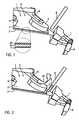
- A method to separate a sticky material from a releasable substrate attached to the sticky material and the respective release apparatus, according to the present invention is described by the following drawings. The drawings show:
- Figure 1
- a perspective view in principle of a release apparatus according to the present invention; and
- Figure 2
- a prospective view on the release apparatus of
Figure 1 showing the process of separation method according to the present invention. - The release apparatus of
Figure 1 is designed as a robot to pick up theadhesive component 1, wherein only the relevant components of the robot are shown. Theadhesive component 1 is to be attached by adhesion to a greater workpiece. Theadhesive component 1 consists of anadhesive material 2 and arelease liner 3. Theadhesive material 2 comprises anadhesive layer 2a with or without a backing 26, such as a plastic film, a fabric, a damping material or a mold component, or theadhesive material 2 comprises stacks ofadhesive layers 2a with or without backing 2b. Opposite to thebacking 2b, therelease liner 3 is attached to theadhesive material 2, wherein therelease liner 3 is held in position by the adhesion of the sticky surface of theadhesive material 2. - The
adhesive component 1 is held bysuction heads 4, placed on thebacking surface 5 of theadhesive component 1. The suction heads 4 and the adhesive component attached thereto are attached to and moved by the robot (not shown) via therobot arms 6. A clamp 7 attached and moved by the robot via afurther robot arm 6, having upper and lower gripper for fixing therelease liner 3 at a portion laterally exceeding theadhesive material 2. Between thesuction head 4 positioned on thebacking surface 5 of theadhesive material 2 and the clamp 7 fixing the portion of therelease liner 3 exceeding theadhesive material 2, an air nozzle 8 is positioned directed to the laterally exceeding portion of therelease liner 3. However, any other position of the air nozzle 8, above the backing surface of theadhesive material 2, and from the downside of theadhesive component 1, the side of therelease liner 3, is possible. - As shown in
Figure 2 , the air nozzle 8 provides an air pulse 9 to the portion of therelease liner 3 exceeding laterally theadhesive material 2. The air pulse 9 providing an impact to therelease liner 3. However, depending on the position of the air nozzle 8, the air pulse 9 and the related impact to the release liner and/or the adhesive material can also be directed to theadhesive material 2 or the downside of therelease liner 3. The air pulse 9 applying a short-term high-impact force on therelease liner 3, that can be regarded as a shock to theadhesive component 1. The short-term high-force shock results in a removal process of therelease liner 3, that is happening in a different frequency area than in a normal peeling off process. Due to the high-force impact at high frequency, the adhesive reacts only in its elastic mold, so that merely the whole force impact of the air pulse 9 is directed to the adhesive connection between therelease liner 3 and theadhesive material 2. Thus, the high frequency shock breaks the connection between therelease liner 3 and theadhesive material 2 at least in a predetermined area, preferably in the vicinity of the portion of therelease liner 3 where the peeling off starts. - Once the adhesion between the
release liner 3 and theadhesive material 2 is reduced or the bond is broken, therelease liner 3 can be peeled off the sticky surface of theadhesive material 2 by a normal peel-offmovement 10 of theadhesive material 2 fixed by the suction heads 4 with respect to therelease liner 3 fixed to clamp 7. The peel offmovement 10 first moves theadhesive material 2 via therobot arm 6 in direction to the clamp 7 holding therelease liner 3 and then moves upwards and backwards, wherein the backward movement increases with the length of therelease liner 3 peeled of theadhesive material 2. Due to the initial loosening of therelease liner 3 from theadhesive material 2, the removal process of therelease liner 3 is performed without any problems, even if the ambient temperatures are high and the bond between theadhesive material 2 and therelease liner 3 is increased due to bleeding of the adhesive. After the peel offmovement 10 is performed resulting in a complete removal of arelease liner 3, the adhesive material is attached with its sticky surface to a greater workpiece by the related robot.
Claims (14)
- Method to separate an adhesive material (2) from a releasable substrate attached to the adhesive material (2) by adhesion using the steps of:fixing the releasable substrate with respect to the adhesive material (2);providing an impact to the releasable substrate and/or the adhesive material (2) to at least reduce adhesion between the releasable substrate and the adhesive material in a determined area;peeling of the releasable substrate from the adhesive material (2).
- Method of claim 1, wherein the impact is provided by an air pulse (9).
- Method of claim 1, wherein the impact is provided by a mechanical impulse.
- Method of one of claims 1 to 3, wherein the releasable substrate is a release liner (3) or a backing material.
- Method of one of claims 1 to 4, wherein the adhesive material comprises one or more adhesive layers with or without a backing.
- Method of one of claims 1 to 5, wherein fixing means, such as suction caps (4) and/or clamps (7), are used for fixing the releasable substrate with respect to the adhesive material (2).
- Method of claim 6, wherein at least one suction cap (4) is attached to the adhesive material (2) and a clamp (7) is attached to the releasable substrate for fixing the releasable substrate with respect to the adhesive material.
- Method of claim 7, wherein the impact is directed to an area of a releasable substrate and/or the adhesive material (2) located between the at least one suction cap (4) attached to the adhesive material (2) and the clamp (7) attached to the releasable substrate.
- Method of claim 7 or 8, wherein the suction cap (4) attached to the adhesive material (2) and the clamp (7) attached to the releasable substrate for fixing the releasable substrate with respect to the adhesive material are moved relative to each other for peeling off the releasable substrate from the adhesive material (2).
- Release apparatus for separating a release liner (3) from an adhesive material (2) comprising fixing means for fixing the adhesive material (2) and fixing means for fixing the release liner (3) with respect to the adhesive material (2) and for peeling off a release liner (3) from the adhesive material (2),
characterized in further comprising an impact unit providing a force impact to the release liner (3) and/or the adhesive material (2) to at least reduce adhesion between the release liner (3) and the adhesive material (2) in a predetermined area prior to peeling of the release liner (3). - Release apparatus of claim 10, wherein the impact unit is an air nozzle (8).
- Release apparatus of claim 10, wherein the impact unit is a mechanical pulse unit controlled by a pneumatic, electric, magnetic or mechanical process.
- Release apparatus of one of claims 10 to 12, wherein the fixing means for fixing the adhesive material (2) is at least one suction cap (4) positioned on surface (5) of the adhesive material (2) opposite the release liner (3).
- Release apparatus of one of claims 10 to 13, wherein the fixing means for fixing the release liner (3) is a clamp (7) positioned on a portion of the release liner (3) exceeding the adhesive material (2).
Priority Applications (1)
| Application Number | Priority Date | Filing Date | Title |
|---|---|---|---|
| EP20090010675 EP2286990B1 (en) | 2009-08-19 | 2009-08-19 | Method to separate an adhesive material from a releasable substrate using an impact |
Applications Claiming Priority (1)
| Application Number | Priority Date | Filing Date | Title |
|---|---|---|---|
| EP20090010675 EP2286990B1 (en) | 2009-08-19 | 2009-08-19 | Method to separate an adhesive material from a releasable substrate using an impact |
Publications (2)
| Publication Number | Publication Date |
|---|---|
| EP2286990A1 EP2286990A1 (en) | 2011-02-23 |
| EP2286990B1 true EP2286990B1 (en) | 2013-10-09 |
Family
ID=41259978
Family Applications (1)
| Application Number | Title | Priority Date | Filing Date |
|---|---|---|---|
| EP20090010675 Not-in-force EP2286990B1 (en) | 2009-08-19 | 2009-08-19 | Method to separate an adhesive material from a releasable substrate using an impact |
Country Status (1)
| Country | Link |
|---|---|
| EP (1) | EP2286990B1 (en) |
Families Citing this family (1)
| Publication number | Priority date | Publication date | Assignee | Title |
|---|---|---|---|---|
| CN104512089A (en) * | 2013-10-08 | 2015-04-15 | 富鼎电子科技(嘉善)有限公司 | Film-stripping method and film-stripping mechanism therewith |
Family Cites Families (4)
| Publication number | Priority date | Publication date | Assignee | Title |
|---|---|---|---|---|
| US4752346A (en) | 1987-07-06 | 1988-06-21 | Hoechst Celanese Corporation | Apparatus and method for separating adherent films |
| US6210524B1 (en) | 1999-09-03 | 2001-04-03 | Avery Dennison Corporation | Method of improving peel-plate dispensability of label constructions |
| DE10013224A1 (en) * | 2000-03-17 | 2001-09-20 | Cd Design Gmbh | Machine for applying decorative and protective sheet, which is coated with adhesive on one side, to car bodywork comprises applicator with convex surface on which sheet is held by suction and which is mounted on robot arm |
| US6488068B2 (en) * | 2001-01-12 | 2002-12-03 | Daimlerchrysler Corporation | Fixture for applying molding to vehicles |
-
2009
- 2009-08-19 EP EP20090010675 patent/EP2286990B1/en not_active Not-in-force
Also Published As
| Publication number | Publication date |
|---|---|
| EP2286990A1 (en) | 2011-02-23 |
Similar Documents
| Publication | Publication Date | Title |
|---|---|---|
| TWI680517B (en) | Film for semiconductor component manufacturing, method for manufacturing semiconductor component, and film for electronic component manufacturing, and method for manufacturing electronic component | |
| JP2022058712A (en) | Manufacturing method for semiconductor processing sheets and semiconductor devices | |
| EP2078740A1 (en) | Heat-peelable pressure-sensitive adhesive sheet and method of recovering adherend | |
| CN102064087B (en) | Dyestripping method, dyestripping device and dyestripping equipment | |
| KR20130141721A (en) | Resin laminate, pressure sensitive adhesive sheet, method for working adherend using the pressure sensitive adhesive sheet, and device for separating the pressure sensitive adhesive sheet | |
| JP2014513426A (en) | Bendable carrier platform, device and method for removing carrier substrate | |
| TW201009037A (en) | Adhesive sheet, method for processing adherend using the adhesive sheet, and adhesive sheet-peeling device | |
| JP5061308B2 (en) | Adhesive sheet | |
| TW201824382A (en) | Cutting device and method for dismounting processing means capable of preventing enlargement of a supporting means even if a processing means is configured to be automatically mounted or dismounted | |
| TWI908808B (en) | Patch application device and patch application method | |
| EP2286990A1 (en) | Method to separate an adhesive material from a releasable substrate using an impact | |
| US9764383B2 (en) | Laser trimming surface cleaning for adhesion to cast metals | |
| TWI735578B (en) | Sheet attaching device and attaching method | |
| JP5767052B2 (en) | Transfer apparatus and transfer method | |
| KR102233172B1 (en) | Double-sided adhesive foam tape and display device comprising the same | |
| JP2010149965A (en) | Protective film peeling device and protective film peeling method | |
| CN109774301B (en) | Label feeding and discharging mechanism and thermal transfer printing device | |
| CN220481753U (en) | Clamping and stripping manipulator and mould pressing equipment for aspherical lenses | |
| JP2005056968A (en) | Method of manufacturing semiconductor device | |
| KR20140114768A (en) | Sheet adhering device and adhering method | |
| CN115552588A (en) | Sheet sticking apparatus and sheet sticking method | |
| JP2011077238A (en) | Method and device for peeling sticking member | |
| JP6431794B2 (en) | Sheet peeling apparatus and peeling method | |
| JP5945158B2 (en) | Sheet peeling apparatus and peeling method | |
| JP5644612B2 (en) | Label peeling jig |
Legal Events
| Date | Code | Title | Description |
|---|---|---|---|
| PUAI | Public reference made under article 153(3) epc to a published international application that has entered the european phase |
Free format text: ORIGINAL CODE: 0009012 |
|
| AK | Designated contracting states |
Kind code of ref document: A1 Designated state(s): AT BE BG CH CY CZ DE DK EE ES FI FR GB GR HR HU IE IS IT LI LT LU LV MC MK MT NL NO PL PT RO SE SI SK SM TR |
|
| AX | Request for extension of the european patent |
Extension state: AL BA RS |
|
| 17P | Request for examination filed |
Effective date: 20110822 |
|
| GRAP | Despatch of communication of intention to grant a patent |
Free format text: ORIGINAL CODE: EPIDOSNIGR1 |
|
| INTG | Intention to grant announced |
Effective date: 20130429 |
|
| GRAS | Grant fee paid |
Free format text: ORIGINAL CODE: EPIDOSNIGR3 |
|
| GRAA | (expected) grant |
Free format text: ORIGINAL CODE: 0009210 |
|
| AK | Designated contracting states |
Kind code of ref document: B1 Designated state(s): AT BE BG CH CY CZ DE DK EE ES FI FR GB GR HR HU IE IS IT LI LT LU LV MC MK MT NL NO PL PT RO SE SI SK SM TR |
|
| REG | Reference to a national code |
Ref country code: GB Ref legal event code: FG4D |
|
| REG | Reference to a national code |
Ref country code: AT Ref legal event code: REF Ref document number: 635370 Country of ref document: AT Kind code of ref document: T Effective date: 20131015 Ref country code: CH Ref legal event code: EP |
|
| REG | Reference to a national code |
Ref country code: IE Ref legal event code: FG4D |
|
| REG | Reference to a national code |
Ref country code: DE Ref legal event code: R096 Ref document number: 602009019290 Country of ref document: DE Effective date: 20131205 |
|
| REG | Reference to a national code |
Ref country code: AT Ref legal event code: MK05 Ref document number: 635370 Country of ref document: AT Kind code of ref document: T Effective date: 20131009 |
|
| REG | Reference to a national code |
Ref country code: NL Ref legal event code: VDEP Effective date: 20131009 |
|
| PG25 | Lapsed in a contracting state [announced via postgrant information from national office to epo] |
Ref country code: SI Free format text: LAPSE BECAUSE OF FAILURE TO SUBMIT A TRANSLATION OF THE DESCRIPTION OR TO PAY THE FEE WITHIN THE PRESCRIBED TIME-LIMIT Effective date: 20131009 |
|
| REG | Reference to a national code |
Ref country code: LT Ref legal event code: MG4D |
|
| PG25 | Lapsed in a contracting state [announced via postgrant information from national office to epo] |
Ref country code: SE Free format text: LAPSE BECAUSE OF FAILURE TO SUBMIT A TRANSLATION OF THE DESCRIPTION OR TO PAY THE FEE WITHIN THE PRESCRIBED TIME-LIMIT Effective date: 20131009 Ref country code: FI Free format text: LAPSE BECAUSE OF FAILURE TO SUBMIT A TRANSLATION OF THE DESCRIPTION OR TO PAY THE FEE WITHIN THE PRESCRIBED TIME-LIMIT Effective date: 20131009 Ref country code: NL Free format text: LAPSE BECAUSE OF FAILURE TO SUBMIT A TRANSLATION OF THE DESCRIPTION OR TO PAY THE FEE WITHIN THE PRESCRIBED TIME-LIMIT Effective date: 20131009 Ref country code: HR Free format text: LAPSE BECAUSE OF FAILURE TO SUBMIT A TRANSLATION OF THE DESCRIPTION OR TO PAY THE FEE WITHIN THE PRESCRIBED TIME-LIMIT Effective date: 20131009 Ref country code: IS Free format text: LAPSE BECAUSE OF FAILURE TO SUBMIT A TRANSLATION OF THE DESCRIPTION OR TO PAY THE FEE WITHIN THE PRESCRIBED TIME-LIMIT Effective date: 20140209 Ref country code: NO Free format text: LAPSE BECAUSE OF FAILURE TO SUBMIT A TRANSLATION OF THE DESCRIPTION OR TO PAY THE FEE WITHIN THE PRESCRIBED TIME-LIMIT Effective date: 20140109 Ref country code: LT Free format text: LAPSE BECAUSE OF FAILURE TO SUBMIT A TRANSLATION OF THE DESCRIPTION OR TO PAY THE FEE WITHIN THE PRESCRIBED TIME-LIMIT Effective date: 20131009 |
|
| PG25 | Lapsed in a contracting state [announced via postgrant information from national office to epo] |
Ref country code: ES Free format text: LAPSE BECAUSE OF FAILURE TO SUBMIT A TRANSLATION OF THE DESCRIPTION OR TO PAY THE FEE WITHIN THE PRESCRIBED TIME-LIMIT Effective date: 20131009 Ref country code: LV Free format text: LAPSE BECAUSE OF FAILURE TO SUBMIT A TRANSLATION OF THE DESCRIPTION OR TO PAY THE FEE WITHIN THE PRESCRIBED TIME-LIMIT Effective date: 20131009 Ref country code: PL Free format text: LAPSE BECAUSE OF FAILURE TO SUBMIT A TRANSLATION OF THE DESCRIPTION OR TO PAY THE FEE WITHIN THE PRESCRIBED TIME-LIMIT Effective date: 20131009 Ref country code: AT Free format text: LAPSE BECAUSE OF FAILURE TO SUBMIT A TRANSLATION OF THE DESCRIPTION OR TO PAY THE FEE WITHIN THE PRESCRIBED TIME-LIMIT Effective date: 20131009 Ref country code: CY Free format text: LAPSE BECAUSE OF FAILURE TO SUBMIT A TRANSLATION OF THE DESCRIPTION OR TO PAY THE FEE WITHIN THE PRESCRIBED TIME-LIMIT Effective date: 20131009 |
|
| PG25 | Lapsed in a contracting state [announced via postgrant information from national office to epo] |
Ref country code: PT Free format text: LAPSE BECAUSE OF FAILURE TO SUBMIT A TRANSLATION OF THE DESCRIPTION OR TO PAY THE FEE WITHIN THE PRESCRIBED TIME-LIMIT Effective date: 20140210 |
|
| REG | Reference to a national code |
Ref country code: DE Ref legal event code: R097 Ref document number: 602009019290 Country of ref document: DE |
|
| PG25 | Lapsed in a contracting state [announced via postgrant information from national office to epo] |
Ref country code: EE Free format text: LAPSE BECAUSE OF FAILURE TO SUBMIT A TRANSLATION OF THE DESCRIPTION OR TO PAY THE FEE WITHIN THE PRESCRIBED TIME-LIMIT Effective date: 20131009 |
|
| PLBE | No opposition filed within time limit |
Free format text: ORIGINAL CODE: 0009261 |
|
| STAA | Information on the status of an ep patent application or granted ep patent |
Free format text: STATUS: NO OPPOSITION FILED WITHIN TIME LIMIT |
|
| PG25 | Lapsed in a contracting state [announced via postgrant information from national office to epo] |
Ref country code: IT Free format text: LAPSE BECAUSE OF FAILURE TO SUBMIT A TRANSLATION OF THE DESCRIPTION OR TO PAY THE FEE WITHIN THE PRESCRIBED TIME-LIMIT Effective date: 20131009 Ref country code: RO Free format text: LAPSE BECAUSE OF FAILURE TO SUBMIT A TRANSLATION OF THE DESCRIPTION OR TO PAY THE FEE WITHIN THE PRESCRIBED TIME-LIMIT Effective date: 20131009 Ref country code: CZ Free format text: LAPSE BECAUSE OF FAILURE TO SUBMIT A TRANSLATION OF THE DESCRIPTION OR TO PAY THE FEE WITHIN THE PRESCRIBED TIME-LIMIT Effective date: 20131009 Ref country code: SK Free format text: LAPSE BECAUSE OF FAILURE TO SUBMIT A TRANSLATION OF THE DESCRIPTION OR TO PAY THE FEE WITHIN THE PRESCRIBED TIME-LIMIT Effective date: 20131009 |
|
| 26N | No opposition filed |
Effective date: 20140710 |
|
| PG25 | Lapsed in a contracting state [announced via postgrant information from national office to epo] |
Ref country code: DK Free format text: LAPSE BECAUSE OF FAILURE TO SUBMIT A TRANSLATION OF THE DESCRIPTION OR TO PAY THE FEE WITHIN THE PRESCRIBED TIME-LIMIT Effective date: 20131009 |
|
| REG | Reference to a national code |
Ref country code: DE Ref legal event code: R097 Ref document number: 602009019290 Country of ref document: DE Effective date: 20140710 |
|
| REG | Reference to a national code |
Ref country code: DE Ref legal event code: R119 Ref document number: 602009019290 Country of ref document: DE |
|
| PG25 | Lapsed in a contracting state [announced via postgrant information from national office to epo] |
Ref country code: MC Free format text: LAPSE BECAUSE OF FAILURE TO SUBMIT A TRANSLATION OF THE DESCRIPTION OR TO PAY THE FEE WITHIN THE PRESCRIBED TIME-LIMIT Effective date: 20131009 Ref country code: LU Free format text: LAPSE BECAUSE OF FAILURE TO SUBMIT A TRANSLATION OF THE DESCRIPTION OR TO PAY THE FEE WITHIN THE PRESCRIBED TIME-LIMIT Effective date: 20140819 |
|
| REG | Reference to a national code |
Ref country code: CH Ref legal event code: PL |
|
| GBPC | Gb: european patent ceased through non-payment of renewal fee |
Effective date: 20140819 |
|
| PG25 | Lapsed in a contracting state [announced via postgrant information from national office to epo] |
Ref country code: CH Free format text: LAPSE BECAUSE OF NON-PAYMENT OF DUE FEES Effective date: 20140831 Ref country code: LI Free format text: LAPSE BECAUSE OF NON-PAYMENT OF DUE FEES Effective date: 20140831 |
|
| REG | Reference to a national code |
Ref country code: IE Ref legal event code: MM4A |
|
| REG | Reference to a national code |
Ref country code: DE Ref legal event code: R119 Ref document number: 602009019290 Country of ref document: DE Effective date: 20150303 |
|
| REG | Reference to a national code |
Ref country code: FR Ref legal event code: ST Effective date: 20150430 |
|
| PG25 | Lapsed in a contracting state [announced via postgrant information from national office to epo] |
Ref country code: GB Free format text: LAPSE BECAUSE OF NON-PAYMENT OF DUE FEES Effective date: 20140819 Ref country code: DE Free format text: LAPSE BECAUSE OF NON-PAYMENT OF DUE FEES Effective date: 20150303 |
|
| PG25 | Lapsed in a contracting state [announced via postgrant information from national office to epo] |
Ref country code: IE Free format text: LAPSE BECAUSE OF NON-PAYMENT OF DUE FEES Effective date: 20140819 Ref country code: FR Free format text: LAPSE BECAUSE OF NON-PAYMENT OF DUE FEES Effective date: 20140901 |
|
| PG25 | Lapsed in a contracting state [announced via postgrant information from national office to epo] |
Ref country code: SM Free format text: LAPSE BECAUSE OF FAILURE TO SUBMIT A TRANSLATION OF THE DESCRIPTION OR TO PAY THE FEE WITHIN THE PRESCRIBED TIME-LIMIT Effective date: 20131009 |
|
| PG25 | Lapsed in a contracting state [announced via postgrant information from national office to epo] |
Ref country code: MT Free format text: LAPSE BECAUSE OF FAILURE TO SUBMIT A TRANSLATION OF THE DESCRIPTION OR TO PAY THE FEE WITHIN THE PRESCRIBED TIME-LIMIT Effective date: 20131009 Ref country code: BG Free format text: LAPSE BECAUSE OF FAILURE TO SUBMIT A TRANSLATION OF THE DESCRIPTION OR TO PAY THE FEE WITHIN THE PRESCRIBED TIME-LIMIT Effective date: 20131009 Ref country code: GR Free format text: LAPSE BECAUSE OF FAILURE TO SUBMIT A TRANSLATION OF THE DESCRIPTION OR TO PAY THE FEE WITHIN THE PRESCRIBED TIME-LIMIT Effective date: 20140110 |
|
| PG25 | Lapsed in a contracting state [announced via postgrant information from national office to epo] |
Ref country code: TR Free format text: LAPSE BECAUSE OF FAILURE TO SUBMIT A TRANSLATION OF THE DESCRIPTION OR TO PAY THE FEE WITHIN THE PRESCRIBED TIME-LIMIT Effective date: 20131009 Ref country code: HU Free format text: LAPSE BECAUSE OF FAILURE TO SUBMIT A TRANSLATION OF THE DESCRIPTION OR TO PAY THE FEE WITHIN THE PRESCRIBED TIME-LIMIT; INVALID AB INITIO Effective date: 20090819 |
|
| PGFP | Annual fee paid to national office [announced via postgrant information from national office to epo] |
Ref country code: BE Payment date: 20170824 Year of fee payment: 9 |
|
| REG | Reference to a national code |
Ref country code: BE Ref legal event code: HC Owner name: NITTO BELGIUM N.V; BE Free format text: DETAILS ASSIGNMENT: CHANGE OF OWNER(S), CHANGEMENT DE NOM DU PROPRIETAIRE; FORMER OWNER NAME: NITTO EUROPE N.V Effective date: 20171207 Ref country code: BE Ref legal event code: HC Owner name: NITTO BELGIUM NV; BE Free format text: DETAILS ASSIGNMENT: CHANGE OF OWNER(S), CHANGEMENT DE NOM DU PROPRIETAIRE, RECTIFICATION; FORMER OWNER NAME: NITTO BELGIUM NV Effective date: 20171215 |
|
| PG25 | Lapsed in a contracting state [announced via postgrant information from national office to epo] |
Ref country code: MK Free format text: LAPSE BECAUSE OF FAILURE TO SUBMIT A TRANSLATION OF THE DESCRIPTION OR TO PAY THE FEE WITHIN THE PRESCRIBED TIME-LIMIT Effective date: 20131009 |
|
| REG | Reference to a national code |
Ref country code: BE Ref legal event code: MM Effective date: 20180831 |
|
| PG25 | Lapsed in a contracting state [announced via postgrant information from national office to epo] |
Ref country code: BE Free format text: LAPSE BECAUSE OF NON-PAYMENT OF DUE FEES Effective date: 20180831 |