EP2286938A2 - Refractory metal core for integrally cast exit trench - Google Patents
Refractory metal core for integrally cast exit trench Download PDFInfo
- Publication number
- EP2286938A2 EP2286938A2 EP10251009A EP10251009A EP2286938A2 EP 2286938 A2 EP2286938 A2 EP 2286938A2 EP 10251009 A EP10251009 A EP 10251009A EP 10251009 A EP10251009 A EP 10251009A EP 2286938 A2 EP2286938 A2 EP 2286938A2
- Authority
- EP
- European Patent Office
- Prior art keywords
- refractory metal
- metal core
- tabs
- main portion
- turbine engine
- Prior art date
- Legal status (The legal status is an assumption and is not a legal conclusion. Google has not performed a legal analysis and makes no representation as to the accuracy of the status listed.)
- Withdrawn
Links
- 239000003870 refractory metal Substances 0.000 title claims abstract description 44
- 238000005266 casting Methods 0.000 claims abstract description 7
- 238000001816 cooling Methods 0.000 claims description 26
- 239000012809 cooling fluid Substances 0.000 claims description 8
- 239000000463 material Substances 0.000 claims description 5
- 229910001182 Mo alloy Inorganic materials 0.000 claims description 2
- ZOKXTWBITQBERF-UHFFFAOYSA-N Molybdenum Chemical compound [Mo] ZOKXTWBITQBERF-UHFFFAOYSA-N 0.000 claims description 2
- 241000251131 Sphyrna Species 0.000 claims description 2
- 229910001092 metal group alloy Inorganic materials 0.000 claims description 2
- 229910052750 molybdenum Inorganic materials 0.000 claims description 2
- 239000011733 molybdenum Substances 0.000 claims description 2
- 238000000576 coating method Methods 0.000 description 8
- 230000008901 benefit Effects 0.000 description 3
- 238000000034 method Methods 0.000 description 3
- 239000011248 coating agent Substances 0.000 description 2
- 239000000356 contaminant Substances 0.000 description 2
- 238000011109 contamination Methods 0.000 description 2
- 238000012986 modification Methods 0.000 description 2
- 230000004048 modification Effects 0.000 description 2
- 238000005452 bending Methods 0.000 description 1
- 239000000919 ceramic Substances 0.000 description 1
- 230000008030 elimination Effects 0.000 description 1
- 238000003379 elimination reaction Methods 0.000 description 1
- 238000002386 leaching Methods 0.000 description 1
- 238000003754 machining Methods 0.000 description 1
- 230000000873 masking effect Effects 0.000 description 1
- 229910052751 metal Inorganic materials 0.000 description 1
- 239000002184 metal Substances 0.000 description 1
- 239000007769 metal material Substances 0.000 description 1
Images

Classifications
-
- F—MECHANICAL ENGINEERING; LIGHTING; HEATING; WEAPONS; BLASTING
- F01—MACHINES OR ENGINES IN GENERAL; ENGINE PLANTS IN GENERAL; STEAM ENGINES
- F01D—NON-POSITIVE DISPLACEMENT MACHINES OR ENGINES, e.g. STEAM TURBINES
- F01D5/00—Blades; Blade-carrying members; Heating, heat-insulating, cooling or antivibration means on the blades or the members
- F01D5/12—Blades
- F01D5/14—Form or construction
- F01D5/18—Hollow blades, i.e. blades with cooling or heating channels or cavities; Heating, heat-insulating or cooling means on blades
- F01D5/187—Convection cooling
-
- B—PERFORMING OPERATIONS; TRANSPORTING
- B22—CASTING; POWDER METALLURGY
- B22C—FOUNDRY MOULDING
- B22C9/00—Moulds or cores; Moulding processes
- B22C9/10—Cores; Manufacture or installation of cores
-
- F—MECHANICAL ENGINEERING; LIGHTING; HEATING; WEAPONS; BLASTING
- F01—MACHINES OR ENGINES IN GENERAL; ENGINE PLANTS IN GENERAL; STEAM ENGINES
- F01D—NON-POSITIVE DISPLACEMENT MACHINES OR ENGINES, e.g. STEAM TURBINES
- F01D5/00—Blades; Blade-carrying members; Heating, heat-insulating, cooling or antivibration means on the blades or the members
- F01D5/12—Blades
- F01D5/14—Form or construction
- F01D5/18—Hollow blades, i.e. blades with cooling or heating channels or cavities; Heating, heat-insulating or cooling means on blades
- F01D5/186—Film cooling
-
- F—MECHANICAL ENGINEERING; LIGHTING; HEATING; WEAPONS; BLASTING
- F05—INDEXING SCHEMES RELATING TO ENGINES OR PUMPS IN VARIOUS SUBCLASSES OF CLASSES F01-F04
- F05D—INDEXING SCHEME FOR ASPECTS RELATING TO NON-POSITIVE-DISPLACEMENT MACHINES OR ENGINES, GAS-TURBINES OR JET-PROPULSION PLANTS
- F05D2230/00—Manufacture
- F05D2230/20—Manufacture essentially without removing material
- F05D2230/21—Manufacture essentially without removing material by casting
-
- F—MECHANICAL ENGINEERING; LIGHTING; HEATING; WEAPONS; BLASTING
- F05—INDEXING SCHEMES RELATING TO ENGINES OR PUMPS IN VARIOUS SUBCLASSES OF CLASSES F01-F04
- F05D—INDEXING SCHEME FOR ASPECTS RELATING TO NON-POSITIVE-DISPLACEMENT MACHINES OR ENGINES, GAS-TURBINES OR JET-PROPULSION PLANTS
- F05D2240/00—Components
- F05D2240/80—Platforms for stationary or moving blades
- F05D2240/81—Cooled platforms
-
- F—MECHANICAL ENGINEERING; LIGHTING; HEATING; WEAPONS; BLASTING
- F05—INDEXING SCHEMES RELATING TO ENGINES OR PUMPS IN VARIOUS SUBCLASSES OF CLASSES F01-F04
- F05D—INDEXING SCHEME FOR ASPECTS RELATING TO NON-POSITIVE-DISPLACEMENT MACHINES OR ENGINES, GAS-TURBINES OR JET-PROPULSION PLANTS
- F05D2300/00—Materials; Properties thereof
- F05D2300/10—Metals, alloys or intermetallic compounds
- F05D2300/13—Refractory metals, i.e. Ti, V, Cr, Zr, Nb, Mo, Hf, Ta, W
Definitions
- the present disclosure relates to a refractory metal core having separate exit tabs which are ganged together within the exterior boundary of a finished cast part and to a turbine engine part formed using the refractory metal core.
- Refractory metal cores have been used to form cooling passages in turbine engine components such as blades and vanes.
- the main portion of the refractory metal core may be configured to create a cooling air passage internal to the component.
- Small tabs extending from the refractory metal core are used to form exit holes associated with the cooling air passage. These individual exit tabs are sometimes connected together outside the envelope of the finished casting to improve the casting process.
- exit holes formed in this manner can restrict the types of coatings that can be subsequently applied or significantly increase the cost of forming the coatings since very thick coatings will cover the holes.
- the cast holes are subject to occasional partial clogging or bending over of edges from handling or contamination, leading to an undesirable decrease in passage cooling flow.
- the present disclosure relates to a refractory metal core for use in casting turbine engine part.
- the refractory metal core broadly comprises a main portion, a plurality of tabs extending from said main portion, and an end portion which at one end joins together some or all of said plurality of tabs.
- the end portion has an opposite edge located prior to an exterior boundary of the part.
- the present disclosure also relates to a turbine engine part having an airfoil portion with a cooling passage formed therein or a part without an airfoil portion which forms the inner or outer gaspath endwalls.
- the cooling passage has a plurality of exit holes and an exit trench which receives cooling fluid from said exit holes.
- the disclosure also covers a turbine engine part having a core of the disclosure therein and a method of forming a cast part comprising placing a core of the disclosure in a mold or die, forming the cast part from a molten metal and removing the core.
- a refractory metal core 10 which may be used to form a cooling passage in a cast part 12, such as a turbine engine component, is illustrated.
- the cast part 12 has a boundary 14.
- the refractory metal core 10 has a main portion 16 with a plurality of tabs 18 extending therefrom.
- the tabs 18 are used to form a series of discrete cast exit holes 20 in the finished casting of the part.
- the tabs 18 extend beyond the boundary 14.
- the tabs 18 may have unjoined ends or one or more sets of joined or ganged ends.
- the tabs 18 may be joined together by a piece 22 of refractory metal material which is located outside the boundary 14.
- the refractory metal core 10' of FIG. 2 may be used to form the cast part 12'.
- the cast part 12' has an exterior boundary 14'.
- the refractory metal core 10' has a main portion 16' which may be configured to form at least one desired cooling passage in the cast part 12'.
- the main portion 16' may be machined so as to form a cooling passage with heat transfer ribs or pedestals, or make a joint to connect to a ceramic core with a serpentine cooling passage.
- a plurality of tabs 18' extend from the main portion 16' and are used to form an array of exit holes 104 for the cooling fluid which exits the cooling passage. As can be seen from FIG.
- the tabs 18' do not extend beyond an exterior or outer boundary 14'.
- the outer boundary 14' could be an exterior surface of the part, such as a pressure sidewall or a suction side wall.
- the outer boundary 14' could also be a trailing edge of an airfoil portion of the part.
- the outer boundary 14' could be the intersegment edge of an endwall in a blade outer air seal or shroud.
- the tabs 18' are joined together by a piece 22' of refractory metal material.
- the piece 22' of refractory metal material forms an exit trench 106 in the final cast part.
- the main portion 16', the tabs 18', and the piece 22' may be integrally formed from a refractory metal material such as molybdenum or a molybdenum alloy.
- the exit trench 106 protects the exit holes 104 from external contamination and handling damage by keeping the terminus of each exit hole 104 inboard of the exterior boundary or edge 14' of the cast part.
- the exit trench 106 creates enough flow area to be much more tolerant of any contaminant buildup in the corners of the opening 26' of the exit trench 106 than individual holes such as those created by the refractory metal core of FIG. 1 would be.
- the slot in the cast part which forms the opening 26' is usefully a single long opening that can be masked in one step for subsequent application of thick external coatings. It can also be more than one long opening formed by ganging together groups of exit tabs. Benefits include reduced variability in actual part flow, reduced cost of coating, and expansion of the variety of coatings that are feasible to use.
- the refractory metal core 10' is placed into a mold or die. After the part 12' has been formed from a molten metal material, the refractory metal core 10' may be removed using any suitable leaching technique known in the art. After the refractory metal core 10' is removed, as shown in FIG. 3 , the cast part 100, such as a vane, is left with at least one cast cooling passage 102, a plurality of cast exit holes 104 cooperating with said at least one cooling passage, and an exit trench 106 for receiving cooling fluid from the exit holes 104.
- the exit holes 104 may be positioned within the trench 106 so that the terminal end of each hole is spaced from an exterior boundary of the part.
- the exit trench 106 may be on an outer endwall edge 108.
- the trench 106 can also be on the forward or aft edge of the platform.
- the exit trench 106 has at least one slot 110 through which cooling fluid is discharged over an exterior section of part 100.
- Turbine engine components which could take advantage of the geometry created by the refractory metal core of FIG. 2 include vane platforms and blade outer air seals or shrouds.
- FIG. 5 illustrates another embodiment of a refractory metal core 10" which may be used to form a cast part with a trench.
- the refractory metal core 10" has main portion 16" with a plurality of tabs 18" connected to the main portion 16" by arms 30". Each tab 18" is called a hammerhead tab because the tab 18" has a width greater than the width of the arm 30" to which it is attached.
- the main portion 16" may be configured to form at least one cooling passage in the cast part 12".
- the main portion 16", the arms 30" and the tabs 18" may be integrally formed for a refractory metal or metal alloy using any suitable technique known in the art. As can be seen in FIG.
- each of the tabs 18" has a length which causes it to extend beyond the exterior or outer boundary 14".
- the arms 30" form cooling passages in the cast part 12" which allows cooling fluid to flow from the cooling passage(s) formed by the main portion 16" and the trenches formed by the tabs 18".
- the cast part will have one hole per short trench segment.
- integral cast cooling flow exit trench there has been described an integral cast cooling flow exit trench. While the integral cast cooling flow exit trench has been described in the context of specific embodiments thereof, other unforeseeable alternatives, modifications and variations may become apparent to those skilled in the art having read the foregoing description. Accordingly, it is intended to embrace those alternatives, modifications, and variations as fall within the broad scope of the appended claims.
Landscapes
- Engineering & Computer Science (AREA)
- Mechanical Engineering (AREA)
- General Engineering & Computer Science (AREA)
- Turbine Rotor Nozzle Sealing (AREA)
- Molds, Cores, And Manufacturing Methods Thereof (AREA)
Abstract
Description
- The present disclosure relates to a refractory metal core having separate exit tabs which are ganged together within the exterior boundary of a finished cast part and to a turbine engine part formed using the refractory metal core.
- Refractory metal cores have been used to form cooling passages in turbine engine components such as blades and vanes. The main portion of the refractory metal core may be configured to create a cooling air passage internal to the component. Small tabs extending from the refractory metal core are used to form exit holes associated with the cooling air passage. These individual exit tabs are sometimes connected together outside the envelope of the finished casting to improve the casting process.
- The exit holes formed in this manner can restrict the types of coatings that can be subsequently applied or significantly increase the cost of forming the coatings since very thick coatings will cover the holes. In addition, the cast holes are subject to occasional partial clogging or bending over of edges from handling or contamination, leading to an undesirable decrease in passage cooling flow.
- The present disclosure relates to a refractory metal core for use in casting turbine engine part. The refractory metal core broadly comprises a main portion, a plurality of tabs extending from said main portion, and an end portion which at one end joins together some or all of said plurality of tabs. The end portion has an opposite edge located prior to an exterior boundary of the part.
- The present disclosure also relates to a turbine engine part having an airfoil portion with a cooling passage formed therein or a part without an airfoil portion which forms the inner or outer gaspath endwalls. The cooling passage has a plurality of exit holes and an exit trench which receives cooling fluid from said exit holes.
- The disclosure also covers a turbine engine part having a core of the disclosure therein and a method of forming a cast part comprising placing a core of the disclosure in a mold or die, forming the cast part from a molten metal and removing the core.
- Other details of the refractory metal core integrally cast exit trench, as well as advantages attendant thereto, are set forth in the following detailed description and the accompanying drawings wherein like reference numerals depict like elements.
-
-
FIG. 1 is a schematic representation of a refractory metal core used to form a cast part; -
FIG. 2 is a schematic representation of a refractory metal core which may be used to form an integral cast exit trench; -
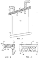
FIG. 3 illustrates a vane outer wall edge having a cast cooling exit trench formed using the refractory metal core ofFIG. 2 ; -
FIG. 4 is a sectional view taken along lines 4-4 ofFig. 3 ; -
FIG. 5 is a schematic representation of an alternative refractory metal core which can also be used. - As shown in
FIG. 1 , arefractory metal core 10 which may be used to form a cooling passage in acast part 12, such as a turbine engine component, is illustrated. As can be seen fromFIG. 1 , thecast part 12 has aboundary 14. Therefractory metal core 10 has amain portion 16 with a plurality oftabs 18 extending therefrom. Thetabs 18 are used to form a series of discretecast exit holes 20 in the finished casting of the part. As can be seen fromFIG. 1 , thetabs 18 extend beyond theboundary 14. Thetabs 18 may have unjoined ends or one or more sets of joined or ganged ends. Thetabs 18 may be joined together by apiece 22 of refractory metal material which is located outside theboundary 14. The use of this type of refractory metal core produces small holes which can be subject to contaminant buildup in the corners of the individual exit hole openings. The individual holes may also require extensive individual masking prior to the application of subsequent coatings to prevent blockage of the hole by the coating. - To alleviate the foregoing issues, the refractory metal core 10' of
FIG. 2 may be used to form the cast part 12'. The cast part 12' has an exterior boundary 14'. The refractory metal core 10' has a main portion 16' which may be configured to form at least one desired cooling passage in the cast part 12'. For example, the main portion 16' may be machined so as to form a cooling passage with heat transfer ribs or pedestals, or make a joint to connect to a ceramic core with a serpentine cooling passage. A plurality of tabs 18' extend from the main portion 16' and are used to form an array ofexit holes 104 for the cooling fluid which exits the cooling passage. As can be seen fromFIG. 2 , the tabs 18' do not extend beyond an exterior or outer boundary 14'. The outer boundary 14' could be an exterior surface of the part, such as a pressure sidewall or a suction side wall. The outer boundary 14' could also be a trailing edge of an airfoil portion of the part. Still further, the outer boundary 14' could be the intersegment edge of an endwall in a blade outer air seal or shroud. The tabs 18' are joined together by a piece 22' of refractory metal material. The piece 22' of refractory metal material forms anexit trench 106 in the final cast part. - The main portion 16', the tabs 18', and the piece 22' may be integrally formed from a refractory metal material such as molybdenum or a molybdenum alloy.
- The
exit trench 106 protects theexit holes 104 from external contamination and handling damage by keeping the terminus of eachexit hole 104 inboard of the exterior boundary or edge 14' of the cast part. Theexit trench 106 creates enough flow area to be much more tolerant of any contaminant buildup in the corners of the opening 26' of theexit trench 106 than individual holes such as those created by the refractory metal core ofFIG. 1 would be. The slot in the cast part which forms the opening 26' is usefully a single long opening that can be masked in one step for subsequent application of thick external coatings. It can also be more than one long opening formed by ganging together groups of exit tabs. Benefits include reduced variability in actual part flow, reduced cost of coating, and expansion of the variety of coatings that are feasible to use. - To form the cast part 12', the refractory metal core 10' is placed into a mold or die. After the part 12' has been formed from a molten metal material, the refractory metal core 10' may be removed using any suitable leaching technique known in the art. After the refractory metal core 10' is removed, as shown in
FIG. 3 , thecast part 100, such as a vane, is left with at least onecast cooling passage 102, a plurality ofcast exit holes 104 cooperating with said at least one cooling passage, and anexit trench 106 for receiving cooling fluid from theexit holes 104. Theexit holes 104 may be positioned within thetrench 106 so that the terminal end of each hole is spaced from an exterior boundary of the part. Theexit trench 106 may be on anouter endwall edge 108. Thetrench 106 can also be on the forward or aft edge of the platform. - The
exit trench 106 has at least oneslot 110 through which cooling fluid is discharged over an exterior section ofpart 100. - Turbine engine components which could take advantage of the geometry created by the refractory metal core of
FIG. 2 include vane platforms and blade outer air seals or shrouds. -
FIG. 5 illustrates another embodiment of arefractory metal core 10" which may be used to form a cast part with a trench. Therefractory metal core 10" hasmain portion 16" with a plurality oftabs 18" connected to themain portion 16" byarms 30". Eachtab 18" is called a hammerhead tab because thetab 18" has a width greater than the width of thearm 30" to which it is attached. Themain portion 16" may be configured to form at least one cooling passage in thecast part 12". Themain portion 16", thearms 30" and thetabs 18" may be integrally formed for a refractory metal or metal alloy using any suitable technique known in the art. As can be seen inFIG. 5 , each of thetabs 18" has a length which causes it to extend beyond the exterior orouter boundary 14". Thearms 30" form cooling passages in thecast part 12" which allows cooling fluid to flow from the cooling passage(s) formed by themain portion 16" and the trenches formed by thetabs 18". Using therefractory metal core 10", the cast part will have one hole per short trench segment. - It is advantageous to cast cooled turbine gaspath hardware with complete cooling passages including exit holes. The integral cast exit holes result in reduced cost due to the elimination of machining operations and provide support to the small cores used for local or in-wall cooling passages.
- In accordance with the present disclosure, there has been described an integral cast cooling flow exit trench. While the integral cast cooling flow exit trench has been described in the context of specific embodiments thereof, other unforeseeable alternatives, modifications and variations may become apparent to those skilled in the art having read the foregoing description. Accordingly, it is intended to embrace those alternatives, modifications, and variations as fall within the broad scope of the appended claims.
Claims (15)
- A refractory metal core (10') for use in casting a turbine engine part (12') which comprises a main portion (16'), a plurality of tabs (18') extending from said main portion (16'), and an end portion (22') having a first edge which joins together said plurality of tabs (18') and a second edge, opposed to the first edge, located internally of an exterior boundary (14') of the cast part (12').
- The refractory metal core of claim 1, wherein said main portion (16') is configured to form at least one cooling passage in said cast part (12').
- The refractory metal core of claim 2, wherein said plurality of tabs (18') are configured to form a plurality of exit holes (104) which cooperate with said at least one cooling passage.
- The refractory metal core of claim 3, wherein said end portion (22') is configured to form an exit trench (106) in said cast part (12').
- The refractory metal core of any preceding claim, wherein said main portion (16'), said plurality of tabs (18'), and said end portion (22') are integrally formed.
- The refractory metal core of any preceding claim, wherein said main portion (16'), said plurality of tabs (18'), and said end portion (22') are formed from a material selected from the group of molybdenum and a molybdenum alloy.
- A turbine engine part (12';12")comprising at least one internal cooling passage, a plurality of exit holes (104) connected to said at least one cooling passage for receiving a cooling fluid, and an exit trench (106) for receiving said cooling fluid from said exit holes (104).
- The turbine engine part according to claim 7, wherein said exit holes (104) have a terminal end spaced from an exterior boundary (14';14") of the part (12';12").
- The turbine engine part of claim 8, further comprising said trench (106) being located between said terminal end of said exit holes (104) and said exterior boundary (14';14").
- The turbine engine part of any of claims 7 to 9, wherein said exit trench (106) has at least one slot (110) associated therewith through which said cooling fluid is discharged over an exterior surface of said turbine engine part (12';12").
- A refractory metal core (10") for use in casting a turbine engine part (12") which comprises a main portion (16"), a plurality of arms (30") extending from said main portion (16"), and a plurality of hammerhead tabs (18") attached to said arms (30").
- The refractory metal core of claim 11, wherein said main portion (16") is configured to form at least one cooling passage in said cast part (12").
- The refractory metal core of claim 11 or 12, wherein said main portion (16"), said arms (30"), and said tabs (18") are integrally formed.
- The refractory metal core of claim 11, 12 or 13 wherein said main portion (16"), said arms (30"), and said tabs (18") are formed from a refractory metal or metal alloy.
- A turbine engine part (12';12") comprising a refractory metal core (10';10") of any of claims 1 to 6 or 11 to 14 cast thereinto.
Applications Claiming Priority (1)
| Application Number | Priority Date | Filing Date | Title |
|---|---|---|---|
| US12/509,608 US20110020115A1 (en) | 2009-07-27 | 2009-07-27 | Refractory metal core integrally cast exit trench |
Publications (2)
| Publication Number | Publication Date |
|---|---|
| EP2286938A2 true EP2286938A2 (en) | 2011-02-23 |
| EP2286938A3 EP2286938A3 (en) | 2015-02-25 |
Family
ID=42614052
Family Applications (1)
| Application Number | Title | Priority Date | Filing Date |
|---|---|---|---|
| EP10251009.6A Withdrawn EP2286938A3 (en) | 2009-07-27 | 2010-05-26 | Refractory metal core for integrally cast exit trench |
Country Status (2)
| Country | Link |
|---|---|
| US (1) | US20110020115A1 (en) |
| EP (1) | EP2286938A3 (en) |
Cited By (1)
| Publication number | Priority date | Publication date | Assignee | Title |
|---|---|---|---|---|
| US10329916B2 (en) | 2014-05-01 | 2019-06-25 | United Technologies Corporation | Splayed tip features for gas turbine engine airfoil |
Families Citing this family (2)
| Publication number | Priority date | Publication date | Assignee | Title |
|---|---|---|---|---|
| US8347945B1 (en) | 2011-07-29 | 2013-01-08 | United Technologies Corporation | Platform interconnected with mid-body core interface for molding airfoil platforms |
| US20140064984A1 (en) * | 2012-08-31 | 2014-03-06 | General Electric Company | Cooling arrangement for platform region of turbine rotor blade |
Citations (2)
| Publication number | Priority date | Publication date | Assignee | Title |
|---|---|---|---|---|
| EP1634665A2 (en) * | 2004-09-09 | 2006-03-15 | United Technologies Corporation | Composite core for use in precision investment casting |
| EP2243930A2 (en) * | 2009-04-17 | 2010-10-27 | General Electric Company | Turbine rotor blade tip |
Family Cites Families (3)
| Publication number | Priority date | Publication date | Assignee | Title |
|---|---|---|---|---|
| GB2163218B (en) * | 1981-07-07 | 1986-07-16 | Rolls Royce | Cooled vane or blade for a gas turbine engine |
| US6612811B2 (en) * | 2001-12-12 | 2003-09-02 | General Electric Company | Airfoil for a turbine nozzle of a gas turbine engine and method of making same |
| US20080131285A1 (en) * | 2006-11-30 | 2008-06-05 | United Technologies Corporation | RMC-defined tip blowing slots for turbine blades |
-
2009
- 2009-07-27 US US12/509,608 patent/US20110020115A1/en not_active Abandoned
-
2010
- 2010-05-26 EP EP10251009.6A patent/EP2286938A3/en not_active Withdrawn
Patent Citations (2)
| Publication number | Priority date | Publication date | Assignee | Title |
|---|---|---|---|---|
| EP1634665A2 (en) * | 2004-09-09 | 2006-03-15 | United Technologies Corporation | Composite core for use in precision investment casting |
| EP2243930A2 (en) * | 2009-04-17 | 2010-10-27 | General Electric Company | Turbine rotor blade tip |
Cited By (2)
| Publication number | Priority date | Publication date | Assignee | Title |
|---|---|---|---|---|
| US10329916B2 (en) | 2014-05-01 | 2019-06-25 | United Technologies Corporation | Splayed tip features for gas turbine engine airfoil |
| US11268387B2 (en) | 2014-05-01 | 2022-03-08 | Raytheon Technologies Corporation | Splayed tip features for gas turbine engine airfoil |
Also Published As
| Publication number | Publication date |
|---|---|
| US20110020115A1 (en) | 2011-01-27 |
| EP2286938A3 (en) | 2015-02-25 |
Similar Documents
| Publication | Publication Date | Title |
|---|---|---|
| US7303375B2 (en) | Refractory metal core cooling technologies for curved leading edge slots | |
| US7744347B2 (en) | Peripheral microcircuit serpentine cooling for turbine airfoils | |
| US7731481B2 (en) | Airfoil cooling with staggered refractory metal core microcircuits | |
| EP1930097B1 (en) | A core for use in a casting mould | |
| EP1972396A1 (en) | Cast features for a turbine engine airfoil | |
| EP1790823B1 (en) | Microcircuit cooling for turbine vanes | |
| EP1467065B1 (en) | Turbine blade | |
| EP2554294B1 (en) | Hybrid core assembly | |
| EP2213838B1 (en) | Casting method for a turbine blade | |
| EP1886745A1 (en) | Blade outer air seal cores and manufacture methods | |
| EP2060745B1 (en) | Gas turbine sealing segment | |
| EP2022941B1 (en) | Turbine blade of a gas turbine engine | |
| EP1876325A2 (en) | External datum system and film cooling hole positioning using core locating holes | |
| EP1923152A1 (en) | Airfoil casting methods | |
| US9669458B2 (en) | Micro channel and methods of manufacturing a micro channel | |
| EP2468433B1 (en) | Drill to flow mini core | |
| EP2385216A2 (en) | Turbine airfoil with body microcircuits terminating in platform | |
| JP2015527529A (en) | Template for forming cooling passages in turbine engine components | |
| EP1106280A1 (en) | Core to control turbine bucket wall thickness and method | |
| EP2286938A2 (en) | Refractory metal core for integrally cast exit trench | |
| EP3034790A1 (en) | Rotating blade for a gas turbine | |
| US20140056716A1 (en) | Bicast turbine engine components | |
| EP3034798A1 (en) | Gas turbine vane | |
| EP2354464A2 (en) | Cast shroud slots with pre-swirled leakage |
Legal Events
| Date | Code | Title | Description |
|---|---|---|---|
| PUAI | Public reference made under article 153(3) epc to a published international application that has entered the european phase |
Free format text: ORIGINAL CODE: 0009012 |
|
| AK | Designated contracting states |
Kind code of ref document: A2 Designated state(s): AL AT BE BG CH CY CZ DE DK EE ES FI FR GB GR HR HU IE IS IT LI LT LU LV MC MK MT NL NO PL PT RO SE SI SK SM TR |
|
| AX | Request for extension of the european patent |
Extension state: BA ME RS |
|
| PUAL | Search report despatched |
Free format text: ORIGINAL CODE: 0009013 |
|
| AK | Designated contracting states |
Kind code of ref document: A3 Designated state(s): AL AT BE BG CH CY CZ DE DK EE ES FI FR GB GR HR HU IE IS IT LI LT LU LV MC MK MT NL NO PL PT RO SE SI SK SM TR |
|
| AX | Request for extension of the european patent |
Extension state: BA ME RS |
|
| RIC1 | Information provided on ipc code assigned before grant |
Ipc: F01D 5/18 20060101ALI20150121BHEP Ipc: B22C 9/10 20060101AFI20150121BHEP |
|
| 17P | Request for examination filed |
Effective date: 20150825 |
|
| RBV | Designated contracting states (corrected) |
Designated state(s): AL AT BE BG CH CY CZ DE DK EE ES FI FR GB GR HR HU IE IS IT LI LT LU LV MC MK MT NL NO PL PT RO SE SI SK SM TR |
|
| RAP1 | Party data changed (applicant data changed or rights of an application transferred) |
Owner name: UNITED TECHNOLOGIES CORPORATION |
|
| STAA | Information on the status of an ep patent application or granted ep patent |
Free format text: STATUS: EXAMINATION IS IN PROGRESS |
|
| 17Q | First examination report despatched |
Effective date: 20170508 |
|
| GRAP | Despatch of communication of intention to grant a patent |
Free format text: ORIGINAL CODE: EPIDOSNIGR1 |
|
| STAA | Information on the status of an ep patent application or granted ep patent |
Free format text: STATUS: GRANT OF PATENT IS INTENDED |
|
| INTG | Intention to grant announced |
Effective date: 20200605 |
|
| STAA | Information on the status of an ep patent application or granted ep patent |
Free format text: STATUS: THE APPLICATION IS DEEMED TO BE WITHDRAWN |
|
| 18D | Application deemed to be withdrawn |
Effective date: 20201016 |
|
| RAP1 | Party data changed (applicant data changed or rights of an application transferred) |
Owner name: RAYTHEON TECHNOLOGIES CORPORATION |