EP1886745A1 - Blade outer air seal cores and manufacture methods - Google Patents
Blade outer air seal cores and manufacture methods Download PDFInfo
- Publication number
- EP1886745A1 EP1886745A1 EP07253070A EP07253070A EP1886745A1 EP 1886745 A1 EP1886745 A1 EP 1886745A1 EP 07253070 A EP07253070 A EP 07253070A EP 07253070 A EP07253070 A EP 07253070A EP 1886745 A1 EP1886745 A1 EP 1886745A1
- Authority
- EP
- European Patent Office
- Prior art keywords
- core
- legs
- portions
- casting
- leg
- Prior art date
- Legal status (The legal status is an assumption and is not a legal conclusion. Google has not performed a legal analysis and makes no representation as to the accuracy of the status listed.)
- Granted
Links
Images


Classifications
-
- B—PERFORMING OPERATIONS; TRANSPORTING
- B22—CASTING; POWDER METALLURGY
- B22C—FOUNDRY MOULDING
- B22C9/00—Moulds or cores; Moulding processes
- B22C9/10—Cores; Manufacture or installation of cores
-
- B—PERFORMING OPERATIONS; TRANSPORTING
- B22—CASTING; POWDER METALLURGY
- B22C—FOUNDRY MOULDING
- B22C7/00—Patterns; Manufacture thereof so far as not provided for in other classes
- B22C7/02—Lost patterns
-
- B—PERFORMING OPERATIONS; TRANSPORTING
- B22—CASTING; POWDER METALLURGY
- B22C—FOUNDRY MOULDING
- B22C9/00—Moulds or cores; Moulding processes
- B22C9/02—Sand moulds or like moulds for shaped castings
-
- B—PERFORMING OPERATIONS; TRANSPORTING
- B22—CASTING; POWDER METALLURGY
- B22C—FOUNDRY MOULDING
- B22C9/00—Moulds or cores; Moulding processes
- B22C9/02—Sand moulds or like moulds for shaped castings
- B22C9/04—Use of lost patterns
Definitions
- the invention relates to gas turbine engines. More particularly, the invention relates to casting of cooled shrouds or blade outer air seals (BOAS).
- BOAS blade outer air seals
- BOAS segments may be internally cooled by bleed air.
- bleed air there may be an upstream-to-downstream array of circumferentially-extending cooling passageway legs within the BOAS. Cooling air may be fed into the passageway legs from the outboard (OD) side of the BOAS (e.g., via one or more inlet ports at ends of the passageway legs). The cooling air may exit the legs through outlet ports in the circumferential ends (matefaces) of the BOAS so as to be vented into the adjacent inter-segment region. The vented air may, for example, help cool adjacent BOAS segments and purge the gap to prevent gas ingestion.
- the BOAS segments may be cast via an investment casting process.
- a ceramic casting core is used to form the passageway legs.
- the core has legs corresponding to the passageway legs.
- the core legs extend between first and second end portions of the core.
- the core may be placed in a die. Wax may be molded in the die over the core legs to form a pattern.
- the pattern may be shelled (e.g., a stuccoing process to form a ceramic shell).
- the wax may be removed from the shell.
- Metal may be cast in the shell over the core.
- the shell and core may be destructively removed. After core removal, the core legs leave the passageway legs in the casting.
- the as-cast passageway legs are open at both circumferential ends of the raw BOAS casting. At least some of the end openings are closed via plug welding, braze pins, or other means. Air inlets to the passageway legs may be drilled from the OD side of the casting.
- One aspect of the invention involves a blade outer air seal (BOAS) casting core.
- the core has first and second end portions and a plurality of legs. Of these legs, first legs each have: a proximal end joining the first end portion; a main body portion; and a free distal portion. Second legs each have: a proximal end joining the second end portion; a main body portion; and a free distal portion.
- the distal portions of the first and second legs may project transverse to the main body portion.
- the core may be formed of refractory metal sheetstock.
- the core may have a ceramic coating.
- the proximal portions may each comprise a reduced cross-section neck.
- At least one third leg may connect to the first end portion to the second end portion.
- the at least one third leg may include first and second perimeter or edge legs.
- a plurality of connector branches may connect adjacent pairs of the legs.
- the connector branches may have minimum cross-sections smaller than adjacent cross-sections of the connected legs.
- the core may be embedded in a shell and a casting cast partially over the core.
- the first and second end portions of the core may project from the casting into the shell.
- the first and second leg distal portions may project into the shell or may terminate in the casting.
- the core may be manufactured by cutting from a refractory metal sheet. After the cutting, the first and second leg distal portions may be bent transverse to associated main body portions of those legs.
- FIG. 1 shows blade outer air seal (BOAS) 20.
- the BOAS has a main body portion 22 having a leading/upstream/forward end 24 and a trailing/downstream/aft end 26.
- the body has first and second circumferential ends or matefaces 28 and 30.
- the body has an ID face 32 and an OD face 34.
- To mount the BOAS to environmental structure 40 (FIG. 3), the exemplary BOAS has a plurality of mounting hooks.
- the exemplary BOAS has a single central forward mounting hook 42 having a forwardly-projecting distal portion recessed aft of the forward end 24.
- the exemplary BOAS has a pair of first and second aft hooks 44 and 46 having rearwardly-projecting distal portions protruding aft beyond the aft end 26.
- a circumferential ring array of a plurality of the BOAS 22 may encircle an associated blade stage of a gas turbine engine.
- the assembled ID faces 32 thus locally bound an outboard extreme of the core flowpath 48 (FIG. 3).
- the BOAS 22 may have features for interlocking the array. Exemplary features include finger and shiplap joints.
- the exemplary BOAS 22 has a pair of fore and aft fingers 50 and 52 projecting from the first circumferential end 28 and which, when assembled, radially outboard of the second circumferential end 30 of the adjacent BOAS.
- the BOAS may be air-cooled.
- bleed air may be directed to a chamber 56 (FIG. 3) immediately outboard of the face 34.
- the bleed air may be directed through ports 60, 62, 64, 66, 68, 70, and 72 (FIG. 2) to an internal cooling passageway network 80.
- the exemplary network includes a plurality of circumferentially-extending legs 82, 84, 86, 88, 90, and 92.
- the network may have a plurality of outlets. Exemplary outlets may include outlets along the circumferential ends 28 and 30.
- outlets 100, 102, and 104 are formed along the first circumferential end 28 and outlets 110, 112, and 114 are formed along the second circumferential end 30.
- adjacent legs may be interconnected by interconnecting passageways 120, 122, 124, 126, and 128.
- the inlet 66 feeds the leg 82 near a closed end 130 of the leg 82.
- the air flows down the leg 82 to an outlet 100 which is in a neck region at the other end 132 of the leg 82.
- the inlet 60 feeds the leg 84 near a closed end 134.
- the outlet 110 is at a neck region at the other end 136.
- the inlets 68 and 70 feed the leg 86 near a closed end 138.
- the outlet 102 is formed at the other end 140.
- the inlet 62 feeds the leg 88 near a closed end 142.
- the outlet 112 is at the other end 144.
- the inlet 72 feeds the leg 90 near a closed end 146.
- the outlet 104 is in a neck region at the other end 148.
- the inlet 64 feeds the leg 92 near a closed end 150.
- the outlet 114 is formed in a neck region at the other end 152.
- FIG. 5 shows a refractory metal core (RMC) 200 for casting the passageway legs.
- the core 200 may be cut from a metallic sheet (e.g., of a refractory metal).
- An exemplary cutting is laser cutting. Alternative cutting may be via a stamping operation.
- the exemplary RMC 200 has first and second end portions 202 and 204.
- First and second perimeter legs 206 and 208 extend between and join the end portions 202 and 204 to form a frame-like structure. Between the perimeter legs 206 and 208, there is an array of legs 210, 212, 214, 216, 218, and 220 which respectively cast the passageway legs 82, 84, 86, 88, 90, and 92.
- each of the RMC legs has a proximal end joining the adjacent one of the end portions 202 and 204 and a free distal end spaced apart from the other end portion.
- a main body of the leg extends between the proximal and distal ends.
- the core leg distal ends 230, 232, 234, 236, 238, and 240 respectively cast the passageway leg closed ends 130, 134, 138, 142, 146, and 150.
- the core leg proximal ends 242, 244, 246, 248, 250, and 252 respectively cast the outlets 100, 110, 102, 112, 104, and 114.
- the prior art plug welding step can be eliminated or reduced.
- the lack of local connection of the core leg free distal ends to the adjacent core end portion 202 or 204 may compromise structural integrity.
- the RMC 200 has connecting portions 260, 262, 264, 266, and 268 connecting the main body portions of the adjacent legs. These connecting portions end up casting the passageways 120, 122, 124, 126, and 128, respectively.
- the connecting portions may advantageously be positioned at locations along the adjacent legs wherein air pressure in the cast passageway legs will be equal. This may minimize cross-flow and reduce losses. However, such location may provide less-than-desirable RMC strengthening. Thus, the connecting portions may be shifted (e.g., pushed circumferentially outward) relative to the optimal pressure balancing locations.
- FIG. 5 also schematically shows a shell 280 having an internal surface 282.
- the shell 280 is formed over a wax pattern containing the RMC 200 for casting the BOAS.
- the inlets 60, 62, 64, 66, 68, 70, and 72 may be drilled (e.g., as part of a machining process applied to the raw casting).
- RMC 200 there may be one or more of several advantages to using the exemplary RMC 200 or modifications thereof.
- Use of the RMC with free distal leg portions may avoid or reduce the need for plug welding.
- Use of an RMC relative to a ceramic core may permit the casting of finer passageways.
- core thickness and passageway height may be reduced relative to those of a baseline ceramic core and its cast passageways.
- Exemplary RMC thicknesses are less than 1.25mm, more narrowly, 0.5-1.0mm.
- the RMC may also readily be provided with features (e.g., stamped/embossed or laser etched recesses) for casting internal trip strips or other surface enhancements.
- FIGS. 6 and 7 show an alternate RMC 400 which may also be cut from refractory metal sheetstock.
- the RMC 400 may be formed otherwise similarly to the RMC 200.
- the RMC 400 has first and second end portions 402 and 404.
- a plurality of legs have free distal end portions 406 bent out of the main plane of the RMC.
- exemplary bends are upwards at bend lines 408 in thinned neck regions 410.
- the distal end portions 406 protrude partially from the pattern wax and become embedded in the ultimate shell 440. Relative to use of the RMC 200, this may provide stronger alignment of the RMC in the shell and, thus, more precise passageway positioning.
- the portion of the distal end portion 406 which had been within the shell cavity leaves a port in the casting.
- This port may be used as the inlet port.
- the port could be enlarged (e.g., by drilling or other machining).
- radially constricting one to all of the interconnecting passageways e.g., 120, 122, 124, 126, and 128) to have a smaller thickness (radial height) than characteristic thickness (e.g., mean, median, or modal) of the adjacent passageway legs.
- This may be provided by a corresponding thinning of the RMC connecting portions (e.g., 260, 262, 264, 266, and 268).
- Exemplary thinning may be from one or both RMC faces and may be performed as part of the main cutting of the RMC or later.
Landscapes
- Engineering & Computer Science (AREA)
- Mechanical Engineering (AREA)
- Molds, Cores, And Manufacturing Methods Thereof (AREA)
- Turbine Rotor Nozzle Sealing (AREA)
- Sealing Using Fluids, Sealing Without Contact, And Removal Of Oil (AREA)
Abstract
Description
- The invention relates to gas turbine engines. More particularly, the invention relates to casting of cooled shrouds or blade outer air seals (BOAS).
- BOAS segments may be internally cooled by bleed air. For example, there may be an upstream-to-downstream array of circumferentially-extending cooling passageway legs within the BOAS. Cooling air may be fed into the passageway legs from the outboard (OD) side of the BOAS (e.g., via one or more inlet ports at ends of the passageway legs). The cooling air may exit the legs through outlet ports in the circumferential ends (matefaces) of the BOAS so as to be vented into the adjacent inter-segment region. The vented air may, for example, help cool adjacent BOAS segments and purge the gap to prevent gas ingestion.
- The BOAS segments may be cast via an investment casting process. In an exemplary casting process, a ceramic casting core is used to form the passageway legs. The core has legs corresponding to the passageway legs. The core legs extend between first and second end portions of the core. The core may be placed in a die. Wax may be molded in the die over the core legs to form a pattern. The pattern may be shelled (e.g., a stuccoing process to form a ceramic shell). The wax may be removed from the shell. Metal may be cast in the shell over the core. The shell and core may be destructively removed. After core removal, the core legs leave the passageway legs in the casting. The as-cast passageway legs are open at both circumferential ends of the raw BOAS casting. At least some of the end openings are closed via plug welding, braze pins, or other means. Air inlets to the passageway legs may be drilled from the OD side of the casting.
- One aspect of the invention involves a blade outer air seal (BOAS) casting core. The core has first and second end portions and a plurality of legs. Of these legs, first legs each have: a proximal end joining the first end portion; a main body portion; and a free distal portion. Second legs each have: a proximal end joining the second end portion; a main body portion; and a free distal portion.
- In various implementations, the distal portions of the first and second legs may project transverse to the main body portion. The core may be formed of refractory metal sheetstock. The core may have a ceramic coating. The proximal portions may each comprise a reduced cross-section neck. At least one third leg may connect to the first end portion to the second end portion. The at least one third leg may include first and second perimeter or edge legs. A plurality of connector branches may connect adjacent pairs of the legs. The connector branches may have minimum cross-sections smaller than adjacent cross-sections of the connected legs.
- The core may be embedded in a shell and a casting cast partially over the core. The first and second end portions of the core may project from the casting into the shell. The first and second leg distal portions may project into the shell or may terminate in the casting.
- The core may be manufactured by cutting from a refractory metal sheet. After the cutting, the first and second leg distal portions may be bent transverse to associated main body portions of those legs.
- The details of one or more embodiments of the invention are set forth in the accompanying drawings and the description below. Other features and advantages of the invention will be apparent from the description and drawings, and from the claims.
-
- FIG. 1 is a view of a blade outer airseal (BOAS).
- FIG. 2 is an OD/top view of the BOAS of FIG. 1.
- FIG. 3 is a first circumferential end view of the BOAS of FIG. 1.
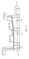
- FIG. 4 is a second circumferential end view of the BOAS of FIG. 1.
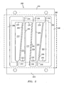
- FIG. 5 is a plan view of a refractory metal core (RMC) for casting a cooling passageway network of the BOAS of FIG. 1.
- FIG. 6 is a plan view of an alternate RMC.
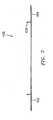
- FIG. 7 is a side view of the RMC of FIG. 6.
- Like reference numbers and designations in the various drawings indicate like elements.
- FIG. 1 shows blade outer air seal (BOAS) 20. The BOAS has a
main body portion 22 having a leading/upstream/forward end 24 and a trailing/downstream/aft end 26. The body has first and second circumferential ends ormatefaces ID face 32 and anOD face 34. To mount the BOAS to environmental structure 40 (FIG. 3), the exemplary BOAS has a plurality of mounting hooks. The exemplary BOAS has a single centralforward mounting hook 42 having a forwardly-projecting distal portion recessed aft of theforward end 24. The exemplary BOAS has a pair of first andsecond aft hooks aft end 26. - A circumferential ring array of a plurality of the
BOAS 22 may encircle an associated blade stage of a gas turbine engine. The assembled ID faces 32 thus locally bound an outboard extreme of the core flowpath 48 (FIG. 3). The BOAS 22 may have features for interlocking the array. Exemplary features include finger and shiplap joints. Theexemplary BOAS 22 has a pair of fore andaft fingers circumferential end 28 and which, when assembled, radially outboard of the secondcircumferential end 30 of the adjacent BOAS. - The BOAS may be air-cooled. For example, bleed air may be directed to a chamber 56 (FIG. 3) immediately outboard of the
face 34. The bleed air may be directed throughports cooling passageway network 80. The exemplary network includes a plurality of circumferentially-extendinglegs exemplary BOAS 22,outlets circumferential end 28 andoutlets circumferential end 30. As is discussed in further detail below, adjacent legs may be interconnected by interconnectingpassageways - In operation, the
inlet 66 feeds theleg 82 near aclosed end 130 of theleg 82. The air flows down theleg 82 to anoutlet 100 which is in a neck region at theother end 132 of theleg 82. Similarly, theinlet 60 feeds theleg 84 near aclosed end 134. Theoutlet 110 is at a neck region at theother end 136. Theinlets leg 86 near aclosed end 138. Theoutlet 102 is formed at theother end 140. Theinlet 62 feeds theleg 88 near aclosed end 142. Theoutlet 112 is at theother end 144. Theinlet 72 feeds theleg 90 near aclosed end 146. Theoutlet 104 is in a neck region at theother end 148. Theinlet 64 feeds theleg 92 near aclosed end 150. Theoutlet 114 is formed in a neck region at theother end 152. - FIG. 5 shows a refractory metal core (RMC) 200 for casting the passageway legs. The
core 200 may be cut from a metallic sheet (e.g., of a refractory metal). An exemplary cutting is laser cutting. Alternative cutting may be via a stamping operation. Theexemplary RMC 200 has first andsecond end portions second perimeter legs end portions perimeter legs legs passageway legs end portions outlets - By using free distal ends of the RMC legs to cast closed passageway leg ends, the prior art plug welding step can be eliminated or reduced. However, the lack of local connection of the core leg free distal ends to the adjacent
core end portion RMC 200 has connectingportions passageways - From an airflow perspective, the connecting portions may advantageously be positioned at locations along the adjacent legs wherein air pressure in the cast passageway legs will be equal. This may minimize cross-flow and reduce losses. However, such location may provide less-than-desirable RMC strengthening. Thus, the connecting portions may be shifted (e.g., pushed circumferentially outward) relative to the optimal pressure balancing locations.
- FIG. 5 also schematically shows a shell 280 having an
internal surface 282. The shell 280 is formed over a wax pattern containing theRMC 200 for casting the BOAS. After dewaxing, casting, and deshelling/decoring, theinlets - There may be one or more of several advantages to using the
exemplary RMC 200 or modifications thereof. Use of the RMC with free distal leg portions may avoid or reduce the need for plug welding. Use of an RMC relative to a ceramic core may permit the casting of finer passageways. For example, core thickness and passageway height may be reduced relative to those of a baseline ceramic core and its cast passageways. Exemplary RMC thicknesses are less than 1.25mm, more narrowly, 0.5-1.0mm. The RMC may also readily be provided with features (e.g., stamped/embossed or laser etched recesses) for casting internal trip strips or other surface enhancements. - FIGS. 6 and 7 show an
alternate RMC 400 which may also be cut from refractory metal sheetstock. TheRMC 400 may be formed otherwise similarly to theRMC 200. TheRMC 400 has first andsecond end portions distal end portions 406 bent out of the main plane of the RMC. For example, exemplary bends are upwards atbend lines 408 in thinnedneck regions 410. After pattern molding, thedistal end portions 406 protrude partially from the pattern wax and become embedded in theultimate shell 440. Relative to use of theRMC 200, this may provide stronger alignment of the RMC in the shell and, thus, more precise passageway positioning. Upon deshelling/decoring, the portion of thedistal end portion 406 which had been within the shell cavity leaves a port in the casting. This port may be used as the inlet port. Alternatively, the port could be enlarged (e.g., by drilling or other machining). - Further variations may involve radially constricting one to all of the interconnecting passageways (e.g., 120, 122, 124, 126, and 128) to have a smaller thickness (radial height) than characteristic thickness (e.g., mean, median, or modal) of the adjacent passageway legs. This may be provided by a corresponding thinning of the RMC connecting portions (e.g., 260, 262, 264, 266, and 268). Exemplary thinning may be from one or both RMC faces and may be performed as part of the main cutting of the RMC or later.
- One or more embodiments of the present invention have been described. Nevertheless, it will be understood that various modifications may be made without departing from the spirit and scope of the invention. For example, when implemented in the reengineering of a baseline BOAS, or using existing manufacturing techniques and equipment, details of the baseline BOAS or existing techniques or equipment may influence details of any particular implementation. Accordingly, other embodiments are within the scope of the following claims.
Claims (20)
- A casting core (200;400) comprising:first and second end portions (202, 204; 402, 404); anda plurality of legs (210...220) including:a plurality of first legs (210,214,218), each having:a proximal end (242,246,250) joining the first end portion (202);a main body portion; anda free distal portion (230,234,238;406); anda plurality of second legs (212,216,220), each having:a proximal end (244,248,252) joining the second end portion (204);a main body portion; anda free distal portion (232,236,240;406).
- The core of claim 1 wherein:the distal portions (406) of the first and second legs project transverse to the main body portion.
- The core of claim 1 or 2 wherein:the core (200;400) is formed of refractory metal sheetstock.
- The core of claim 3 wherein:the core (200;400) has a ceramic coating.
- The core of claim 3 or 4 wherein:the sheetstock has a thickness of 0.5-1.0mm.
- The core of any preceding claim wherein:the proximal portions (242...252) of the first and second legs (210...220) each comprises a reduced cross-section neck.
- The core of any preceding claim further comprising:at least one third leg (206,208) connecting the first end portion (202) to the second end portion (204).
- The core of claim 7 wherein:said at least one third leg includes first and second perimeter legs (206,208).
- The core of any preceding claim further comprising:a plurality of connector branches (260...268) connecting adjacent pairs of said legs (210...220) and having minimum cross-section smaller than adjacent cross-sections of the connected legs (210...220).
- The core of claim 9 wherein:the connector branches (260...268) have smaller thickness than characteristic thickness of the connected legs (210...220).
- A raw casting, shell, and core combination comprising: shell;the core (200;400) of any preceding claim; anda casting partially over said core (200;400), the first and second end portions (202,204;402,404) projecting from the casting into the shell (280;440).
- The combination of claim 11 wherein:the distal portions (230...240) of the first and second legs (210...220) project from the casting into the shell (280;440).
- The combination of claim 11 or 12 wherein:distal portions (230...240) terminate in the casting.
- A method comprising:cutting a refractory metal sheet to define:first and second end portions (202,204;402,404); anda plurality of legs (210...220) including:a plurality of first legs (210,214,218), each having:a proximal end (242,246,250) joining the first end portion (202);a main body portion; anda distal portion (244,248,252); anda plurality of second legs, each having:a proximal end joining the second end portion (204);a main body portion; anda distal portion (232,236,240;406); andbending the first and second leg distal portions (406) transverse to the associated main body portion.
- The method of claim 14 wherein:the cutting comprises laser cutting.
- The method of claim 14 or 15 wherein:the cutting comprises:cutting the first leg distal portions (406) from the second end portion (404); andcutting the second leg distal portions (406) from the from first end portion (402).
- The method of claim 14, 15 or 16 further comprising:applying a coating at least to the first and second leg portions.
- The method of any of claims 14 to 17 further comprising:molding a sacrificial material over the first and second leg portions to form a pattern;shelling the pattern, the first and second end portions (402,404) and the distal portions (406) projecting from the sacrificial material into the shell (280;440);removing the sacrificial material;casting metal in the shell (280;440); andremoving the shell (280;440).
- The method of claim 18 used to form a blade outer air seal (20) and further comprising:directing air into the seal through inlets cast by the first and second leg distal portions (406).
- The method of claim 19 or 20 further comprising:drilling a plurality of outlet holes from a first face of the casting to passageways within the casting cast by the first and second leg portions; anddischarging the air through the outlet holes.
Applications Claiming Priority (1)
| Application Number | Priority Date | Filing Date | Title |
|---|---|---|---|
| US11/502,046 US7686068B2 (en) | 2006-08-10 | 2006-08-10 | Blade outer air seal cores and manufacture methods |
Publications (2)
| Publication Number | Publication Date |
|---|---|
| EP1886745A1 true EP1886745A1 (en) | 2008-02-13 |
| EP1886745B1 EP1886745B1 (en) | 2009-03-11 |
Family
ID=38823173
Family Applications (1)
| Application Number | Title | Priority Date | Filing Date |
|---|---|---|---|
| EP07253070A Active EP1886745B1 (en) | 2006-08-10 | 2007-08-03 | Blade outer air seal cores and manufacture methods |
Country Status (8)
| Country | Link |
|---|---|
| US (1) | US7686068B2 (en) |
| EP (1) | EP1886745B1 (en) |
| JP (1) | JP2008044011A (en) |
| KR (1) | KR20080014587A (en) |
| CN (1) | CN101121192A (en) |
| DE (1) | DE602007000674D1 (en) |
| RU (1) | RU2007130632A (en) |
| SG (1) | SG139617A1 (en) |
Cited By (1)
| Publication number | Priority date | Publication date | Assignee | Title |
|---|---|---|---|---|
| EP3533532A1 (en) * | 2018-03-01 | 2019-09-04 | Rolls-Royce plc | A core for an investment casting process |
Families Citing this family (18)
| Publication number | Priority date | Publication date | Assignee | Title |
|---|---|---|---|---|
| US8122583B2 (en) * | 2007-06-05 | 2012-02-28 | United Technologies Corporation | Method of machining parts having holes |
| US8066052B2 (en) * | 2007-06-07 | 2011-11-29 | United Technologies Corporation | Cooled wall thickness control |
| US7874792B2 (en) * | 2007-10-01 | 2011-01-25 | United Technologies Corporation | Blade outer air seals, cores, and manufacture methods |
| US9238970B2 (en) | 2011-09-19 | 2016-01-19 | United Technologies Corporation | Blade outer air seal assembly leading edge core configuration |
| US9103225B2 (en) | 2012-06-04 | 2015-08-11 | United Technologies Corporation | Blade outer air seal with cored passages |
| US20130340966A1 (en) | 2012-06-21 | 2013-12-26 | United Technologies Corporation | Blade outer air seal hybrid casting core |
| US20140064969A1 (en) * | 2012-08-29 | 2014-03-06 | Dmitriy A. Romanov | Blade outer air seal |
| US20140064942A1 (en) * | 2012-08-31 | 2014-03-06 | General Electric Company | Turbine rotor blade platform cooling |
| US9803491B2 (en) | 2012-12-31 | 2017-10-31 | United Technologies Corporation | Blade outer air seal having shiplap structure |
| US10006367B2 (en) * | 2013-03-15 | 2018-06-26 | United Technologies Corporation | Self-opening cooling passages for a gas turbine engine |
| US9797262B2 (en) | 2013-07-26 | 2017-10-24 | United Technologies Corporation | Split damped outer shroud for gas turbine engine stator arrays |
| EP3030754B1 (en) | 2013-08-06 | 2018-11-14 | United Technologies Corporation | Boas with radial load feature |
| WO2015130380A2 (en) * | 2013-12-19 | 2015-09-03 | United Technologies Corporation | Blade outer air seal cooling passage |
| US10316683B2 (en) | 2014-04-16 | 2019-06-11 | United Technologies Corporation | Gas turbine engine blade outer air seal thermal control system |
| US10221767B2 (en) | 2014-09-02 | 2019-03-05 | United Technologies Corporation | Actively cooled blade outer air seal |
| US10329934B2 (en) | 2014-12-15 | 2019-06-25 | United Technologies Corporation | Reversible flow blade outer air seal |
| US10815827B2 (en) | 2016-01-25 | 2020-10-27 | Raytheon Technologies Corporation | Variable thickness core for gas turbine engine component |
| US11193386B2 (en) | 2016-05-18 | 2021-12-07 | Raytheon Technologies Corporation | Shaped cooling passages for turbine blade outer air seal |
Citations (6)
| Publication number | Priority date | Publication date | Assignee | Title |
|---|---|---|---|---|
| US5092735A (en) * | 1990-07-02 | 1992-03-03 | The United States Of America As Represented By The Secretary Of The Air Force | Blade outer air seal cooling system |
| US5375973A (en) * | 1992-12-23 | 1994-12-27 | United Technologies Corporation | Turbine blade outer air seal with optimized cooling |
| EP1467065A2 (en) * | 2003-04-08 | 2004-10-13 | United Technologies Corporation | Turbine blade |
| EP1531019A1 (en) * | 2003-10-16 | 2005-05-18 | United Technologies Corporation | Refractory metal core wall thickness control |
| EP1611978A1 (en) * | 2004-06-14 | 2006-01-04 | United Technologies Corporation | Investment casting |
| EP1772209A2 (en) * | 2005-09-01 | 2007-04-11 | United Technologies Corporation | Investment casting pattern manufacture |
-
2006
- 2006-08-10 US US11/502,046 patent/US7686068B2/en active Active
-
2007
- 2007-03-28 KR KR1020070030076A patent/KR20080014587A/en not_active Application Discontinuation
- 2007-04-19 SG SG200702856-6A patent/SG139617A1/en unknown
- 2007-08-03 EP EP07253070A patent/EP1886745B1/en active Active
- 2007-08-03 DE DE602007000674T patent/DE602007000674D1/en active Active
- 2007-08-06 JP JP2007203996A patent/JP2008044011A/en active Pending
- 2007-08-10 CN CNA2007101408696A patent/CN101121192A/en active Pending
- 2007-08-10 RU RU2007130632/02A patent/RU2007130632A/en not_active Application Discontinuation
Patent Citations (6)
| Publication number | Priority date | Publication date | Assignee | Title |
|---|---|---|---|---|
| US5092735A (en) * | 1990-07-02 | 1992-03-03 | The United States Of America As Represented By The Secretary Of The Air Force | Blade outer air seal cooling system |
| US5375973A (en) * | 1992-12-23 | 1994-12-27 | United Technologies Corporation | Turbine blade outer air seal with optimized cooling |
| EP1467065A2 (en) * | 2003-04-08 | 2004-10-13 | United Technologies Corporation | Turbine blade |
| EP1531019A1 (en) * | 2003-10-16 | 2005-05-18 | United Technologies Corporation | Refractory metal core wall thickness control |
| EP1611978A1 (en) * | 2004-06-14 | 2006-01-04 | United Technologies Corporation | Investment casting |
| EP1772209A2 (en) * | 2005-09-01 | 2007-04-11 | United Technologies Corporation | Investment casting pattern manufacture |
Cited By (1)
| Publication number | Priority date | Publication date | Assignee | Title |
|---|---|---|---|---|
| EP3533532A1 (en) * | 2018-03-01 | 2019-09-04 | Rolls-Royce plc | A core for an investment casting process |
Also Published As
| Publication number | Publication date |
|---|---|
| JP2008044011A (en) | 2008-02-28 |
| US7686068B2 (en) | 2010-03-30 |
| DE602007000674D1 (en) | 2009-04-23 |
| US20090301680A1 (en) | 2009-12-10 |
| KR20080014587A (en) | 2008-02-14 |
| CN101121192A (en) | 2008-02-13 |
| SG139617A1 (en) | 2008-02-29 |
| EP1886745B1 (en) | 2009-03-11 |
| RU2007130632A (en) | 2009-02-20 |
Similar Documents
| Publication | Publication Date | Title |
|---|---|---|
| EP1886745B1 (en) | Blade outer air seal cores and manufacture methods | |
| US7874792B2 (en) | Blade outer air seals, cores, and manufacture methods | |
| US7650926B2 (en) | Blade outer air seals, cores, and manufacture methods | |
| EP2000232B1 (en) | Cooled wall with thickness control | |
| EP1772209B1 (en) | Investment casting pattern manufacture | |
| EP1813775B1 (en) | Film cooled component of gas turbine engine | |
| US8137068B2 (en) | Castings, casting cores, and methods | |
| US7731481B2 (en) | Airfoil cooling with staggered refractory metal core microcircuits | |
| US10184353B2 (en) | Blade outer air seal cooling scheme | |
| EP1923152B1 (en) | Trubine blade casting method |
Legal Events
| Date | Code | Title | Description |
|---|---|---|---|
| PUAI | Public reference made under article 153(3) epc to a published international application that has entered the european phase |
Free format text: ORIGINAL CODE: 0009012 |
|
| AK | Designated contracting states |
Kind code of ref document: A1 Designated state(s): AT BE BG CH CY CZ DE DK EE ES FI FR GB GR HU IE IS IT LI LT LU LV MC MT NL PL PT RO SE SI SK TR |
|
| AX | Request for extension of the european patent |
Extension state: AL BA HR MK YU |
|
| 17P | Request for examination filed |
Effective date: 20080128 |
|
| 17Q | First examination report despatched |
Effective date: 20080325 |
|
| GRAP | Despatch of communication of intention to grant a patent |
Free format text: ORIGINAL CODE: EPIDOSNIGR1 |
|
| AKX | Designation fees paid |
Designated state(s): DE GB |
|
| GRAS | Grant fee paid |
Free format text: ORIGINAL CODE: EPIDOSNIGR3 |
|
| GRAA | (expected) grant |
Free format text: ORIGINAL CODE: 0009210 |
|
| AK | Designated contracting states |
Kind code of ref document: B1 Designated state(s): DE GB |
|
| REG | Reference to a national code |
Ref country code: GB Ref legal event code: FG4D |
|
| REF | Corresponds to: |
Ref document number: 602007000674 Country of ref document: DE Date of ref document: 20090423 Kind code of ref document: P |
|
| PLBE | No opposition filed within time limit |
Free format text: ORIGINAL CODE: 0009261 |
|
| STAA | Information on the status of an ep patent application or granted ep patent |
Free format text: STATUS: NO OPPOSITION FILED WITHIN TIME LIMIT |
|
| 26N | No opposition filed |
Effective date: 20091214 |
|
| REG | Reference to a national code |
Ref country code: DE Ref legal event code: R082 Ref document number: 602007000674 Country of ref document: DE Representative=s name: SCHMITT-NILSON SCHRAUD WAIBEL WOHLFROM PATENTA, DE |
|
| REG | Reference to a national code |
Ref country code: DE Ref legal event code: R082 Ref document number: 602007000674 Country of ref document: DE Representative=s name: SCHMITT-NILSON SCHRAUD WAIBEL WOHLFROM PATENTA, DE Ref country code: DE Ref legal event code: R081 Ref document number: 602007000674 Country of ref document: DE Owner name: UNITED TECHNOLOGIES CORP. (N.D.GES.D. STAATES , US Free format text: FORMER OWNER: UNITED TECHNOLOGIES CORP., HARTFORD, CONN., US |
|
| PGFP | Annual fee paid to national office [announced via postgrant information from national office to epo] |
Ref country code: DE Payment date: 20200721 Year of fee payment: 14 |
|
| REG | Reference to a national code |
Ref country code: DE Ref legal event code: R119 Ref document number: 602007000674 Country of ref document: DE |
|
| PG25 | Lapsed in a contracting state [announced via postgrant information from national office to epo] |
Ref country code: DE Free format text: LAPSE BECAUSE OF NON-PAYMENT OF DUE FEES Effective date: 20220301 |
|
| PGFP | Annual fee paid to national office [announced via postgrant information from national office to epo] |
Ref country code: GB Payment date: 20230720 Year of fee payment: 17 |