EP2286558B1 - System und verfahren zur unterbrechung eines sendegerätes in einem kommunikationssystem - Google Patents
System und verfahren zur unterbrechung eines sendegerätes in einem kommunikationssystem Download PDFInfo
- Publication number
- EP2286558B1 EP2286558B1 EP09763266.5A EP09763266A EP2286558B1 EP 2286558 B1 EP2286558 B1 EP 2286558B1 EP 09763266 A EP09763266 A EP 09763266A EP 2286558 B1 EP2286558 B1 EP 2286558B1
- Authority
- EP
- European Patent Office
- Prior art keywords
- call
- transmitting
- channel
- interrupt request
- frames
- Prior art date
- Legal status (The legal status is an assumption and is not a legal conclusion. Google has not performed a legal analysis and makes no representation as to the accuracy of the status listed.)
- Active
Links
Images






Classifications
-
- H—ELECTRICITY
- H04—ELECTRIC COMMUNICATION TECHNIQUE
- H04M—TELEPHONIC COMMUNICATION
- H04M3/00—Automatic or semi-automatic exchanges
- H04M3/20—Automatic or semi-automatic exchanges with means for interrupting existing connections; with means for breaking-in on conversations
-
- H—ELECTRICITY
- H04—ELECTRIC COMMUNICATION TECHNIQUE
- H04L—TRANSMISSION OF DIGITAL INFORMATION, e.g. TELEGRAPHIC COMMUNICATION
- H04L47/00—Traffic control in data switching networks
- H04L47/10—Flow control; Congestion control
- H04L47/24—Traffic characterised by specific attributes, e.g. priority or QoS
- H04L47/245—Traffic characterised by specific attributes, e.g. priority or QoS using preemption
-
- H—ELECTRICITY
- H04—ELECTRIC COMMUNICATION TECHNIQUE
- H04L—TRANSMISSION OF DIGITAL INFORMATION, e.g. TELEGRAPHIC COMMUNICATION
- H04L47/00—Traffic control in data switching networks
- H04L47/10—Flow control; Congestion control
- H04L47/32—Flow control; Congestion control by discarding or delaying data units, e.g. packets or frames
-
- H—ELECTRICITY
- H04—ELECTRIC COMMUNICATION TECHNIQUE
- H04W—WIRELESS COMMUNICATION NETWORKS
- H04W76/00—Connection management
- H04W76/20—Manipulation of established connections
- H04W76/28—Discontinuous transmission [DTX]; Discontinuous reception [DRX]
-
- H—ELECTRICITY
- H04—ELECTRIC COMMUNICATION TECHNIQUE
- H04W—WIRELESS COMMUNICATION NETWORKS
- H04W4/00—Services specially adapted for wireless communication networks; Facilities therefor
- H04W4/06—Selective distribution of broadcast services, e.g. multimedia broadcast multicast service [MBMS]; Services to user groups; One-way selective calling services
-
- H—ELECTRICITY
- H04—ELECTRIC COMMUNICATION TECHNIQUE
- H04W—WIRELESS COMMUNICATION NETWORKS
- H04W76/00—Connection management
- H04W76/30—Connection release
- H04W76/34—Selective release of ongoing connections
- H04W76/36—Selective release of ongoing connections for reassigning the resources associated with the released connections
Definitions
- This disclosure relates generally to communication systems, and more particularly, to a system and method for interrupting a transmitting device in a communication system.
- Wireless communication systems generally comprise a set of radios and a set of base stations.
- the radios which may be mobile radios, portable radios or the like, are generally the endpoints of a communication path, while base stations are typically stationary intermediates by which a communication path to a radio device is established or maintained.
- a first police officer needing back up may need to interrupt a second police officer that is engaged in a call.
- US 5,091,906 A describes a method for interrupting a radio transmission in a quasi-duplex radio-frequency communication system.
- the method of the present invention includes the step of transmitting a signal with periodically-occurring holes therein by a first communication unit to at least a second communication unit.
- Terrestrial Trunked Radio (TETRA); Technical requirements for Direct Mode Operation (DMO); Part 3: Mobile Station to Mobile Station (MS-MS) Air Interface (AI) protocol; Final draft ETSI EN 300 396-3", ETSI STANDARDS, LIS, SOPHIA ANTIPOLIS CEDEX, FRANCE, vol. TETRA, no. V1.3.0, 1 April 2006 (2006-04-01), XP014033803, ISSN: 0000-0001 describes the Terrestrial Trunked Radio standard.
- GB 2 358 557 A describes a quiescent period in the primary communication in FDMA communications between two or more primary radios.
- the quiescent period is used by secondary radios to communicate with each other.
- CORDEIRO C ET AL "An introduction to the first wireless Standard based on Cognitive Radios", JOURNAL OF COMMUNICATIONS, ACADEMY PUBLISHERS, OULU, FI, vol. 1, no. 1, 1 April 2006 (2006-04-01), pages 38-47, XP002486875, ISSN: 1796-2021 describes an air interface standard based on CR techniques.
- the present disclosure provides a system and method for interrupting a transmitting device during a call.
- calls are transmitted from a first device on a communication channel as a series of channel frames, which may be, for example, a series of bursts in a TDMA system, a series of payload frames in an FDMA, and the like.
- the transmitting device is configured to drop channel frames, resulting in open channel frame periods where the transmitting device is not transmitting on the communication channel. During these open channel frame periods, the transmitting device is also configured to switch to a receiving mode.
- Other devices in the system such as any radios or base stations receiving the call, are then capable of ascertaining the timing of the open channel frame periods and switching into a transmitting mode during the open channel frame periods. If another device in the system needs to interrupt the transmitting device, that other device is configured to send an interrupt request on the communication channel to the transmitting device in order to request access to the channel. Upon receiving the interrupt request, the transmitting device ceases or pauses transmission, allowing the other device to then begin transmitting a new call on that same communication channel.
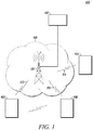
- FIG. 1 illustrates an exemplary communication system 100 that may be used for implementing the present disclosure.
- Communication system 100 comprises mobile communication devices 102, 104, and 106, which may be for example, portable or mobile radios, personal digital assistants, cellular telephones, video terminals, portable computers with a wireless modem, or any other wireless devices.
- the communication devices may be referred to as "radios", but they are also referred to in the art as subscribers, mobile stations, mobile equipment, mobiles, portables, handsets, etc.
- Radios 102, 104, and 106 communicate over a radio access network 108 via wireless communication resources.
- the radio access network 108 may comprise infrastructure such as, but not limited to, base stations (with a single base station 110 shown for clarity), base station controllers (not shown), network elements (such as a mobile switching center, home location register, visitor location register, etc.), and the like, to facilitate the communications between radios having access to the radio access network 108.
- base station 110 may also be configured to communicate with one or more dispatch console sites 118.
- the wireless communication resources used for communication between the base station 110 and radios 102, 104, and 106 may include any type of communication resource such as, for example, radio frequency (RF) technologies, including, but not limited to TDMA; Code Division Multiple Access (CDMA), FDMA, Orthogonal Frequency Division Multiple Access (OFDMA) and the like.
- RF radio frequency
- CDMA Code Division Multiple Access
- FDMA Frequency Division Multiple Access
- OFDMA Orthogonal Frequency Division Multiple Access
- Other wireless technologies such as those now known or later to be developed and including, but not limited to, infrared, Bluetooth, electric field, electromagnetic, or electrostatic transmissions, may also offer suitable substitutes.
- radios 102, 104, and 106 may communicate with one another either in “repeater mode” or in “direct mode.” In repeater mode, the radios 102, 104, and 106 may communicate with each other by radio 102 establishing a wireless link or radio connection 112 with base station 110 over an available RF channel, radio 104 establishing a wireless link 114 with base station 110 over an available RF channel, and radio 106 establishing a wireless link 116 with base station 110 over an available RF channel.
- base station 110 comprises one or more repeater devices that receive a signal from one of the radios 102, 104, or 106 over the respective link 112, 114, or 116 and retransmit the signal to one or more of the other radios.
- Communication from a radio 102, 104, or 106 to base station 110 are generally referred to as being inbound while communications from base station 110 to a radio 102, 104, or 106 are generally referred to as being outbound.
- radios in direct mode (also commonly referred to as talkaround mode), radios (e.g., radios 102 and 106) may communicate directly, without a base station, by establishing a wireless link with one another.
- direct mode also commonly referred to as talkaround mode
- radios e.g., radios 102 and 106
- present disclosure is equally applicable to both direct mode communications and communications via base station 110.
- system 100 may also include various other elements not shown in FIG 1 .
- the system 100 may also include many more base stations than is shown in FIG. 1 .
- FIGS. 2-10 One exemplary embodiment of the present disclosure is illustrated in FIGS. 2-10 .
- This illustrated embodiment is described with reference to a TDMA system compliant with European Telecommunications Institute (ETSI) standards TS 102 361.
- ETSI European Telecommunications Institute
- TS 102 European Telecommunications Institute
- ETSI TS 102 490 ETSI-dPMR standard
- each TDMA carrier signal 200 is divided into numerous time slots or communication streams.
- the TDMA carrier signal 200 is illustrated having two time slots, labeled respectively as "1" and "2", although it should be understood that a TDMA carrier signal in accordance with the present disclosure could also have any number of time slots, such as 4, 8, 16 or any other potential number of time slots.
- Each time slot includes discrete information packets 202 and 204 (also referred to herein as “bursts” or more generically as “channel frames”) configured to carry a specific amount of information.
- sub-slots 206 may also be provided between each of the bursts.
- the sub-slots 206 typically include a Common Announcement Channel (CACH) signal.
- CACH Common Announcement Channel
- the sub-slots 206 typically provide guard time between bursts.
- the communication channel may be comprised of one or more time slots.
- each communication channel may be comprised of one or more time slots for transmitting the call from a radio to the base station (i.e., an inbound channel link), and one or more time slots for transmitting the call from the base station (i.e., an outbound channel link).
- the base station i.e., an inbound channel link
- the base station i.e., an outbound channel link
- only one channel link is generally required to transmit the call.
- FIG. 3 illustrates one example of a multi-burst structure for a TDMA call signal, in accordance with protocols set out in ETSI standard TS 102 361, that may be utilized to transmit call information on a TDMA carrier signal 200.
- the TDMA call signal 300 is separated into multiple superframes 302.
- Each superframe 302 includes six individual bursts A, B, C, D, E, and F, each of which is 27.5ms in duration. Every 360ms during a call, this superframe burst sequence is repeated.
- Each voice call may also begin with a header 304.
- the header 304 may include a link control header burst, which may contain information, such as a manufacturer ID, a talkgroup ID, a source ID, and a destination ID. It should also be understood that header 304 may be comprised of multiple header bursts, each containing different types of information.
- each burst A-F includes a payload field 306, an EMB field 308 and an embedded signaling field 310.
- the payload field 306 includes the particular media information being transmitted (i.e., voice, data, control, video, etc.) and is comprised of three information frames: IF1, IF2, and IF3.
- the second information frame, IF2 is split into two parts, one on either side of the embedded signaling field 310.
- each information frame in bursts A-F corresponds to 20ms of voice information.
- the embedded signaling field 310 may include synchronization and other control data.
- the embedded signaling field 310 of burst A includes a voice frame synchronization signal, while the embedded signaling fields of the remaining bursts include Link Control information or other signaling information.
- Such synchronization and signaling information may be comprised of various information elements as are well known in the art.
- the EMB field 308 includes information elements that define the meaning of the payload field. For example, in accordance with ETSI standard TS 102 361, the EMB field 308 may include information elements such as color code information, link control start stop (LCSS) bits, a privacy bit, and EMB parity.
- LCSS link control start stop
- a communication device that is in the process of transmitting a call (also referred to as a "transmitting device") is configured to periodically or intermittently drop channel frames (i.e., bursts in a TDMA system or payload frames in an FDMA system) during transmission.
- the transmitting device is configured to not transmit a channel frame during a predetermined set of channel frame periods. During these predetermined channel periods, the transmitting device is also configured to switch over into a receiving mode in order to listen for any incoming transmissions.
- an open channel frame period For purposes of this disclosure, a channel period during which a transmitting device does not transmit a frame is referred to as an "open channel frame period.” In the case of a TDMA system, an open channel frame period may also be referred to as an "open burst period.” Similarly, in the case of an FDMA system, an open channel frame period may also be referred to as an "open payload frame period.” It should also be understood that the term “call” is meant to include any type of multimedia transmission, as well as transmissions comprising system control information.
- Communication devices that are in the process of receiving the call may also be configured to switch, when necessary, into a transmitting mode in order to initiate transmissions during an open channel frame period. As will be explained in further detail below, this permits non-transmitting devices in the communication system to send interrupt requests to the transmitting device in order to request use of the channel being utilized by the transmitting device, and permits the transmitting device to receive such interrupt requests while transmitting.
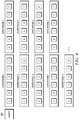
- FIG. 4 illustrates one exemplary embodiment for transmitting a TDMA call signal in accordance with the present disclosure.
- the transmitting device is configured to drop a burst every third superframe, and more particularly, to drop an F burst during every third superframe. That is, the transmitting device does not transmit the F burst from every third superframe.
- Each open burst period in FIG. 4 is illustrated using the letters "Dr" to indicate that no burst was transmitted during that burst period.
- each set of three superframes is also identified as superframes 1, 2, and 3, with superframe 3 having the open burst period.
- the F burst is dropped because, in accordance with the signaling structure described in FIG. 3 , the F burst generally includes the least significant control information as compared to other bursts in the superframe. However, it is understood that other bursts in the superframe may also be selected to be dropped.
- the transmitting device may also be configured to alternate dropping different bursts in the superframes.
- the duration between dropped bursts may be altered as a matter of design choice. Increasing the duration between dropped bursts decreases the amount of call information that is lost from the transmission but also increases the amount of time between opportunities when a non-transmitting device can request access to the channel, and vice-versa. For example, in the embodiment described above for a 2-slot TDMA system, a burst is dropped every third superframe and, therefore, the time between open burst periods is 1080ms. If the burst is alternatively dropped every sixth superframe, the call quality may be increased but the time between open burst periods would be increased to 2160ms.
- the transmitted call signal may also employ signaling to identify the timing of the open burst period.
- the transmitted link control information may transmit certain information during the superframe prior to the superframe which will provide the open burst period (i.e., superframe 2 in FIG. 4 ) to indicate that the next superframe will contain an open burst period.
- the transmitted call signal may also transmit information to indicate that the transmitted signal is utilizing burst dropping in its transmission, which allows receiving devices to determine whether the transmitting device can be interrupted using the process described herein. This is especially useful in a communication system in which only a portion of the devices are configured to operate using the present disclosure.
- This information may be transmitted during a header burst 304, in the link control information of each burst, or as any other type of message.
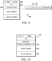
- the link control message 900 includes a service options field 902, which further includes a Burst Dropping (BD) information element 904, and a Penultimate Superframe (PS) information element 906.
- the BD information element 904 is comprised of a single bit that is set to the value 1 if the transmitting device is dropping bursts while transmitting.
- the PS information element 906 is also comprised of a single bit that is set to the value 1 during the superframe immediately preceding a superframe having an open burst period (i.e., a superframe 2 in FIG.
- the link control message 900 may also include a Feature Set ID ("FID") information element 910.
- the FID information element 910 may include a standard ID if the transmitted call is not using dropping bursts, or may include a proprietary ID if the transmitted call is dropping bursts. In one embodiment, the proprietary ID may be a manufacturer's ID.
- the remaining information elements illustrated in the link control message are well known and are therefore not discussed in any further detail herein. It should also be understood that this link control message 900 is but one example. Thus, the relevant information elements may be provided in different portions of the link control message 900. Other information elements in the link control message 900 may also be used to provide similar functionality. For example, rather than using a BD information element 904 or FID information element 910, the OPCODE information element 908 may additionally or alternatively be configured to indicate that the transmission is using burst dropping.
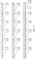
- FIG. 5 illustrates one exemplary embodiment for generating, at a transmitting device, the signaling structure in FIG. 4 .
- the bursts are generated so as to minimize the impact of the dropped burst on the call quality.
- each burst is comprised of three information frames, each of which is encoded with a predetermined amount of call information (e.g., 20ms of voice information for voice calls).
- the six bursts A-F that make up each superframe are typically comprised of a total of eighteen information frames (e.g., 360ms of voice information for voice calls).
- fifty-four information frames, numbered 1 through 54, for three consecutive superframes 1-3 are illustrated.
- one information frame is discarded at the end of each superframe.
- bursts A-F in superframe 1 are generated using information frames 1-18.
- Information frame 19 is then discarded and bursts A-F for superframe 2 are generated using bursts 20-37.
- information frame 38 is discarded and bursts A-E of superframe 3 are generating using information frames 39-53.
- Information frame 54 is then also discarded, and the F burst for superframe 3 is dropped (i.e., the F burst is not transmitted, but the channel timing remains intact, thus leaving an open burst period). This process is repeated for each series of three superframes. As a result, the effect of the dropped burst on the quality of a call, and in particular a voice call, is diminished because only a single information frame is lost from each superframe.
- any of the information frames may be chosen to be discarded for each superframe.
- the communication device may also be configured to simply generate the first two superframes using information frames 1-36, generate the third superframe using information frames 37-51, and then discard information frames 52-54.
- the call information may also be buffered by a predetermined amount of time prior to initiating transmission. For example, in the embodiment described above in which three 20ms information frames are to be discarded every three superframes, it would be desirable to provide at least a 60ms buffer before initiating transmission.
- FIG. 6 illustrates one exemplary embodiment for receiving a call that is transmitted using the methods shown in FIGS. 4 and 5 .
- the receiving device extracts the information frames from each received burst in order to provide the encoded call information to the user.
- information frames 1-3 are extracted from burst A in superframe 1
- information frames 4-6 are then extracted from burst B in superframe 1, and so on.
- the receiving device plays a mitigated information frame before beginning the next superframe.
- the receiving device plays a mitigated information frame 19.
- the receiving device plays a mitigated information frame 38; and after receiving information frames 39-53, the receiving device plays a mitigated information frame 54. This process is then repeated for each series of three superframes.
- the mitigated information frames may be generated using various techniques known in the art. For example, in one embodiment, a mitigated information frame may be generated by interpolating between the information frames received immediately before and after the time when a mitigate information frame is to be inserted. In another embodiment, a mitigated information frame may be generated by repeating the prior information frame. In another embodiment, a mitigated information frame may be generated by playing the subsequently received information frame twice. In yet another embodiment, the mitigated information frame may simply be a muted frame.
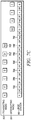
- FIGS. 7a-7c illustrate one exemplary embodiment of a method by which a non-transmitting device may interrupt a transmitting device in accordance with the present disclosure. More particularly, FIGS. 7a-7c describe an embodiment in which a non-transmitting device (i.e., an "interrupting device") needs to interrupt a transmitting device that is transmitting a call via a base station 110 in repeater mode.
- a non-transmitting device i.e., an "interrupting device”
- radio 102 is the transmitting device
- radio 104 is the interrupting device.
- the various blocks shown in FIGS. 7a-7c indicate transmission of the various bursts and signals from the respective communication devices.
- the transmitting device 102 is illustrated transmitting a series of TDMA bursts to a base station 110 on a first TDMA time slot (i.e. the "inbound channel link"). Each burst is received by the base station 110 and retransmitted during a subsequent burst period to other communication devices on another TDMA time slot (i.e., the "outbound channel link").
- burst "A" is transmitted from the transmitting device 102, received by the base station 110, and retransmitted during the next available burst period on the outbound channel link.
- bursts are typically transmitted to other communication devices in the system one burst period after the burst has been transmitted from the transmitting device.
- the transmitting device 102 is also configured to periodically drop a burst during transmission.
- the base station 110 does not receive a burst from the transmitting device 102
- the base station transmits an erasure burst 404 on the following burst period of the outbound channel link to indicate that no call information was received from the transmitting device.
- the erasure burst 404 is typically comprised of three erasure information frames. The structure and function of an erasure information frame that is used for an erasure burst is well known in the art and is therefore not discussed any further herein.
- an interrupting device 104 transmits, during an open burst period 702, an interrupt request 706 on the inbound channel link.
- the interrupt request 706 may be sent automatically upon a user keying a call at the interrupting device 706.
- the interrupting device may also be configured with a transmitter interrupt button to permit the user of the interrupting device to manually request transmission of the interrupt signal.
- the interrupting device 104 may also be configured to provide a user perceivable notification to the user to indicate that the interrupt request 706 has been sent.
- the user perceivable notification may be an audible signal, a visual cue, or any other type of notification that can be perceived by the user.
- it may be desirable to interrupt the transmitting device For example, it may be desirable to interrupt a transmitting device if another device needs to transmit an emergency call. It may also be desirable to interrupt a transmitting device if a higher-priority device needs to initiate a call. It may also be desirable to interrupt a transmitting device if a non-transmitting device needs to send an urgent data message or an event indicator to the transmitting device. If devices in the communication system are configured to permit remote monitoring (i.e., allowing one device to remotely activate the microphone of another device), it may also be desirable to also remotely interrupt or dekey the device being monitored.
- the illustrated interrupting device in FIGS. 7a-7c is a radio, it should be understood that the interrupting device may be any other device.
- the base station may be configured to transmit an interrupt request to a transmitting device upon receiving a command from a console site or other device to interrupt the transmitting device.
- the interrupt request may be configured to cause the transmitting device to either completely cease transmitting or to pause for a certain amount of time.
- the base station 110 after receiving the interrupt request 706, may generate and transmit an acknowledgement signal 708 to the interrupting device 104 on the outbound channel link to indicate that the interrupt request 706 had been received.
- the acknowledgement signal 708 may be transmitted within an embedded signaling field of an erasure burst, although other message structures may also be used.
- the base station 110 begins broadcasting the interrupt request 706 on the outbound channel link during the next superframe in which the transmitting device is expected to drop a burst.
- the interrupt request 706 is broadcast during each burst period (i.e., A-F) of the superframe in which an open burst period 402 is expected (e.g., a superframe 3 in FIG. 4 ). Since the transmitting device 102 switches to a receive mode during the open burst period 402, the transmitting device 102 receives the interrupt request 706 during this open burst period 402. Any other device listening to the call also receives the interrupt request 706, thus indicating to each such device that the transmitting device is about to be interrupted.
- the number of times that the interrupt request is actually transmitted by the base station 110 is a matter of design choice so long as at least one such transmission coincides with the open burst period 702. For example, increasing the number of times an interrupt request is transmitted increases the likelihood that the interrupt request will be received by devices listening to the call, while decreasing the number of time an interrupt request is transmitted decreases the amount of the transmitted call that is truncated by the base station 110.
- the transmitting device 102 After receiving the interrupt request 706, the transmitting device 102 takes an appropriate action based the received interrupt request. In the embodiment illustrated in FIG. 7c , the transmitting device 102 send an acknowledgement message 710 on the inbound channel link during the next available burst period and then ceases transmitting. However, the transmitting device 102 may also be configured to take other actions depending on the interrupt request received. For example, the transmitting device may be configured to pause transmission for a certain amount of time. The transmitting device 102 may also be configured to provide a user perceivable notification to the user to indicate that an interrupt request has been received.
- the base station 110 upon receiving the acknowledgment message 710, stops broadcasting the interrupt request, and transmits the acknowledgment message 710 on the outbound channel link to the interrupting device 104. Once the interrupting device 104 receives the acknowledgement message 710, the interrupting device 104 begins transmitting on the inbound channel link. If the call is a voice call, the interrupting device may also be configured to provide a user perceivable notification to the user to indicate that the interrupt request has been acknowledged and to inform the user that they may begin speaking.
- the transmitting device 102 may also be configured to transmit multiple instances of an acknowledgement message 710 after receiving an interrupt request 706 to decrease the risk of the acknowledgement message 710 being lost. In another embodiment, the transmitting device 102 may also be configured to continue transmitting the acknowledgement message 710 until it has been properly received by the base station 110. For example, the transmitting device 102 may be configured to alternate between transmitting an acknowledgement message 710 and listening to the outbound channel link until the transmitting device 102 determines that the base station 110 is no longer broadcasting the interrupt request 706.
- FIG. 8 illustrates another exemplary embodiment of the present disclosure in which a transmitting device is operating in direct mode.
- each burst is transmitted directly from the transmitting device 102 to each device listening to the call.
- radio 102 is the transmitting device and radio 106 is the interrupting device.
- the transmitting device 102 is also configured to periodically drop a burst during transmission.
- an interrupting device 106 if an interrupting device 106 has determined that the transmitting device 102 is to be interrupted, the interrupting device 106 transmits, during an open burst period 802, an interrupt request 804 to the transmitting device 102.
- the transmitting device 102 After receiving the interrupt request, the transmitting device 102 takes appropriate actions. In the embodiment shown in FIG. 8 , this includes transmitting to the interrupting device 106 an acknowledgement message 806 during the next available burst period and then ceasing transmission. Upon receiving the acknowledgment message 806, the interrupting device 106 begins transmitting.
- the transmitting device 102 in FIG. 8 may also be configured to provide a user perceivable notification upon receiving an interrupt request, and the interrupting device may be configured to provide a user receivable notification upon sending the interrupt request and/or receiving acknowledgement of the interrupt request from the transmitting device.
- the transmitting device may also be configured to transmit the acknowledgement message multiple time to increase the chance of it being received, or to continue transmitting the acknowledgement message until it is determined that the interrupting device has received the acknowledgement message and begun transmitting.
- FIG. 10 illustrates one exemplary embodiment of an interrupt request 706 that may be utilized in TDMA communication system described above.
- the interrupt request 706 may in the form of a Control Signaling Block ("CSBK") message.
- the interrupt request 706 includes an interrupt type information element 1002.
- the interrupt type information element 1002 may be utilized to indicate the purpose of the interrupt request.
- the interrupt type information element 1002 may be comprised of 5 bits in which the value 00001 indicates interruption from a higher priority call, 00010 indicates interruption of by an emergency call, and 00011 indicates interruption of a device that is being remotely monitored.
- additional types of interrupt requests may also be provided for and any values may be used for each type.
- the interrupt type information element 1002 may also be configured to indicate whether the transmitting device is to cease transmitting or simply pause for a certain amount of time.
- the interrupt request 706 further includes a target address information element 1004 and a source address information element 1006.
- the target address information element 1004 identifies the address of the transmitting device to be interrupted
- the source address information element 1006 identifies the device that is requesting access to the channel.
- the remaining information elements shown in the interrupt request are well known information elements utilized in CSBK signals and are therefore not discussed in any further detail herein.
- TDMA call signal described above in FIGS. 4 , 5 , and 6 could easily be based upon the air interface protocol described in the ETSI TS 102 361 standard (ETSI-DMR standard).
- ETSI-DMR standard ETSI-DMR standard
- ETSI-dPMR air interface protocol described in the ETSI TS 102 490 standard
- ETSI-dPMR air interface protocol described in the ETSI TS 102 490 standard
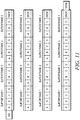
- FIG. 11 FDMA call signals are typically separated into superframes each having four payload frames A-D, with each payload frame having four information frames.
- payload frames may be periodically dropped to create open payload frame periods.
- sufficient open payload frame periods may be produced by dropping a payload frame every fourth superframe in accordance with an embodiment of the present disclosure.
- an FDMA call signal having superframes comprising four payload frames, one payload frame from every fourth superframe is not transmitted in order to provide an interrupt opportunity for another device.
- an information frame may also be discarded every 16 information frames so that only one information frame is discarded during each superframe.
- FIG. 12 illustrates a method for generating the FDMA call signal with payload frames comprising four information frames and one information frame of every sixteen information frames is discarded in such a way to allow every sixteenth payload frame to not be transmitted in order to provide an interrupt opportunity for another device in accordance with an embodiment of the present disclosure.
- the rate of dropped payload frames and/or the selected information frames to be discarded may be altered.
- FIG. 13 illustrates a method for receiving an FDMA call signal with payload frames comprising four information frames and one mitigated information frame is inserted after every sixteen received information frames in accordance with an embodiment of the present disclosure. It should be readily apparent to those skilled in the art that other embodiments are possible which employ different channel frame dropping rates and different information frame dropping rates while using FDMA call signals, TDMA call signals, or other types of call signal.
Landscapes
- Engineering & Computer Science (AREA)
- Signal Processing (AREA)
- Computer Networks & Wireless Communication (AREA)
- Mobile Radio Communication Systems (AREA)
Claims (15)
- Ein Verfahren zum Unterbrechen einer Übertragungsvorrichtung, die einen Anruf in einem Kommunikationssystem (100) überträgt, wobei das Verfahren umfasst:eine erste Vorrichtung (102), die Anrufinformation eines Anrufs codiert, der in eine Reihe von Kanalrahmen übertragen wird;wobei die erste Vorrichtung (102) in einem Übertragungsmodus arbeitet und den Anruf auf einen Kommunikationskanal über die Reihe von Kanalrahmen überträgt, wobei der Anruf von mehreren Vorrichtungen annehmbar ist, und die erste Vorrichtung (102) eine Vielzahl von offenen Kanalrahmenperioden auf den Kommunikationskanal während des Übertragens des Anrufs durch intermittierendes Auslassen, anstelle des Übertragens, einer entsprechenden vorbestimmten Vielzahl der Kanalrahmen einfügt;wobei die erste Vorrichtung (102) während einer der eingefügten offenen Kanalrahmenperioden zu einem Empfangsmodus wechselt und während des Empfangsmodus' bestimmt, ob ein Unterbrechungsantrag von einer zweiten Vorrichtung (104) der Vielzahl von Vorrichtungen übertragen und an der ersten Vorrichtung (102) empfangen wurde, wobei die erste Vorrichtung und die Vielzahl von Vorrichtungen mobile oder drahtlose Kommunikationsvorrichtungen sind; undreagierend auf die erste Vorrichtung (102) bestimmt, dass ein Unterbrechungsantrag zum Anfordern der Verwendung des Kanals von der zweiten Vorrichtung (104) übertragen und in der ersten Vorrichtung empfangen wurde, als eine Funktion des Unterbrechungsantrages, mindestens eines von:der ersten Vorrichtung (102), die das Übertragen des Anrufs beendet; undder ersten Vorrichtung (102), die das Übertragen des Anrufs für eine vorbestimmte Zeitperiode aussetzt.
- Das Verfahren nach Anspruch 1, wobei der Unterbrechungsantrag von der ersten Vorrichtung (102) direkt von der zweiten Vorrichtung (104) oder von der zweiten Vorrichtung (104) über eine Basisstation empfangen wird.
- Das Verfahren nach Anspruch 1, wobei:der Anruf als eine Reihe von Überrahmen übertragen wird, wobei jeder Überrahmen einen oder mehrere Kanalrahmen aufweist, unddie Vielzahl von offenen Kanalrahmenperioden periodisch während des Übertragens des Anrufs bereitgestellt wird.
- Das Verfahren nach Anspruch 3, wobei jede der Serien von Kanalrahmen eine vorbestimmte Anzahl von Informationsrahmen umfasst und wobei das Verfahren ferner im Übertragungsmodus umfasst:Kodieren einer Reihe von Informationsrahmen;Generieren der Reihe von Kanalrahmen aus der Reihe von Informationsrahmen; undperiodisches Verwerfen eines Informationsrahmens, während die Reihe von Kanalrahmen generiert wird.
- Das Verfahren nach Anspruch 4, wobei ein Informationsrahmen nach dem Übertragen jedes Überrahmens verworfen wird.
- Das Verfahren nach Anspruch 1, ferner umfassend das Übertragen einer Bestätigungsnachricht, die den Empfang des Unterbrechungsantrags an die zweite Vorrichtung (104) nach dem Empfangen des Unterbrechungsantrags bestätigt.
- Ein Verfahren zum Unterbrechen einer Übertragungsvorrichtung in einem Kommunikationssystem, wobei das Verfahren umfasst:eine erste Vorrichtung (104) einer Vielzahl von Vorrichtungen, die in einem Empfangsmodus arbeitet und einen ersten Anruf auf einem Kommunikationskanal über eine Reihe von Kanalrahmen von einer zweiten Vorrichtung empfängt, wobei der erste Anruf von der Vielzahl von Vorrichtungen annehmbar ist, und wobei eine Vielzahl von offenen Kanalrahmenperioden auf den Kommunikationskanal während des Übertragens des Anrufs durch die zweite Vorrichtung (102) eingefügt wird, die eine entsprechende vorbestimmte Vielzahl der Kanalrahmen intermittierend auslässt, anstelle zu übertragen, wobei die Vielzahl der Vorrichtungen und die zweite Vorrichtung mobile oder drahtlose Kommunikationsvorrichtungen sind;wobei die erste Vorrichtung (104) bestimmt, dass der erste Anruf, der von der zweiten Vorrichtung (102) übertragen wird, zu unterbrechen ist;wobei die erste Vorrichtung (104) während einer der durch die zweite Vorrichtung (102) eingefügten offenen Kanalrahmenperioden vom Betrieb im Empfangsmodus zum Betrieb in einem Übertragungsmodus wechselt; undwobei die erste Vorrichtung (104), im Übertragungsmodus und während der einen der offenen Kanalrahmenperioden, ein Unterbrechungsantrag an die zweite Vorrichtung (102) überträgt, um die Verwendung des Kanals anzufordern.
- Das Verfahren nach Anspruch 7, ferner umfassend die erste Vorrichtung (104), die nach dem Übertragen des Unterbrechungsantrages einen zweiten Anruf auf den Kommunikationskanal übertragt.
- Das Verfahren nach Anspruch 7, ferner umfassend die erste Vorrichtung (104), die bestimmt, ob eine Bestätigung des Unterbrechungsantrages von der zweiten Vorrichtung (102) empfangen wurde, und die erste Vorrichtung, die den zweiten Anruf in Reaktion auf den Empfang der Bestätigung überträgt.
- Das Verfahren nach Anspruch 7, wobei die erste Vorrichtung konfiguriert ist zum Bestimmen ob der zweite Anruf eine Vielzahl von offenen Kanalrahmenperioden umfasst, und zum Wechseln in den Übertragungsmodus nur reagierend auf das Bestimmen, dass der zweite Anruf eine Vielzahl von offenen Kanalrahmenperioden umfasst.
- Das Verfahren nach Anspruch 1, wobei die zweite Vorrichtung eine Basisstation ist und der Unterbrechungsantrag von der Basisstation als Reaktion auf den Empfang eines Befehls von einer Konsole und einer anderen drahtlosen Vorrichtung zum Unterbrechen der ersten Vorrichtung übertragen wird.
- Ein System zum Unterbrechen einer Übertragungsvorrichtung, die einen Anruf in einem Kommunikationssystem überträgt, umfassend:eine erste Vorrichtung (102), die konfiguriert ist zum:Codieren von Anrufinformation eines Anrufs, der in eine Reihe von Kanalrahmen zu übertragen ist;Arbeiten in einem Übertragungsmodus und Übertragen eines ersten Anrufs auf einen Kommunikationskanal über die Reihe von Kanalrahmen, wobei der Anruf von einer Vielzahl von Vorrichtungen annehmbar ist;Einfügen einer Vielzahl von offenen Kanalrahmenperioden auf den Kommunikationskanal während des Übertragens des ersten Anrufs durch, anstelle des Übertragens, intermittierendes Auslassen einer entsprechenden vorbestimmten Vielzahl der Kanalrahmen;Wechseln in einen Empfangsmodus während mindestens einer der eingefügten Vielzahl von offenen Kanalrahmenperioden;Empfangen eines Anrufunterbrechungsantrages von einer zweiten Vorrichtung (104) und, als eine Funktion des Unterbrechungsantrages, Beenden des Übertragens des Anrufs oder Aussetzen des Übertragens des Anrufs für eine vorbestimmte Zeitdauer;die zweite Vorrichtung (104), die konfiguriert ist zum:Empfangen des ersten Anrufs auf dem Kommunikationskanal; undBestimmen, dass der erste Anruf, der von der ersten Vorrichtung übertragen wird, zu unterbrechen ist und darauf reagierend Wechseln in einen Übertragungsmodus während einer der offenen Kanalrahmenperioden und Übertragen des Anrufunterbrechungsantrages an die erste Vorrichtung (102) zum Anfordern der Verwendung des Kanals; undwobei die erste Vorrichtung, die zweite Vorrichtung und die Vielzahl von Vorrichtungen mobile oder drahtlose Kommunikationsvorrichtungen sind.
- Das System nach Anspruch 12, wobei die zweite Vorrichtung nach dem Übertragen des Anrufunterbrechungsantrages zum Übertragen eines zweiten Anrufs auf den Kommunikationskanal konfiguriert ist.
- Das System nach Anspruch 12, wobei der erste Anruf direkt von der ersten Vorrichtung (102) zu der zweiten Vorrichtung (104) oder von der ersten Vorrichtung (102) zu der zweiten Vorrichtung (104) über eine Basisstation übertragen wird.
- Das System nach Anspruch 12, wobei der erste Anruf von der ersten Vorrichtung zu der zweiten Vorrichtung über eine Basisstation übertragen wird und die Basisstation konfiguriert ist, um den Unterbrechungsantrag von der zweiten Vorrichtung während einer ersten der Vielzahl von offenen Kanalrahmenperioden zu empfangen, und den Unterbrechungsantrag auf den Kommunikationskanal während einer oder mehrerer aufeinanderfolgenden offenen Kanalperioden der Vielzahl von offenen Kanalperioden zu wiederholen.
Applications Claiming Priority (2)
| Application Number | Priority Date | Filing Date | Title |
|---|---|---|---|
| US12/136,177 US8605650B2 (en) | 2008-06-10 | 2008-06-10 | System and method for interrupting a transmitting device in a communication system |
| PCT/US2009/045563 WO2009151975A2 (en) | 2008-06-10 | 2009-05-29 | System and method for interrupting a transmitting device in a communication system |
Publications (3)
| Publication Number | Publication Date |
|---|---|
| EP2286558A2 EP2286558A2 (de) | 2011-02-23 |
| EP2286558A4 EP2286558A4 (de) | 2011-10-19 |
| EP2286558B1 true EP2286558B1 (de) | 2018-04-25 |
Family
ID=41400245
Family Applications (1)
| Application Number | Title | Priority Date | Filing Date |
|---|---|---|---|
| EP09763266.5A Active EP2286558B1 (de) | 2008-06-10 | 2009-05-29 | System und verfahren zur unterbrechung eines sendegerätes in einem kommunikationssystem |
Country Status (6)
| Country | Link |
|---|---|
| US (2) | US8605650B2 (de) |
| EP (1) | EP2286558B1 (de) |
| CN (1) | CN102057636B (de) |
| AU (1) | AU2009257779B2 (de) |
| CA (1) | CA2727405C (de) |
| WO (1) | WO2009151975A2 (de) |
Families Citing this family (12)
| Publication number | Priority date | Publication date | Assignee | Title |
|---|---|---|---|---|
| US8605650B2 (en) * | 2008-06-10 | 2013-12-10 | Motorola Solutions, Inc. | System and method for interrupting a transmitting device in a communication system |
| AU2008362078B2 (en) * | 2008-09-28 | 2013-02-28 | Hytera Communications Corp. Ltd. | Method for implementing digital mobile radio private network communication, digital mobile radio private network communication terminal, relay station and system |
| GB2511708B (en) | 2011-12-30 | 2017-06-21 | Motorola Solutions Inc | Frequency allocation for preemption calls in a trunked radio communication system |
| US9253773B2 (en) * | 2013-08-29 | 2016-02-02 | Motorola Solutions, Inc. | Method and apparatus for wirelessly transacting simultaneous voice and data on adjacent timeslots |
| EP3082364B1 (de) * | 2013-12-11 | 2018-10-31 | Hytera Communications Corp., Ltd. | Kommunikationsverfahren auf grundlage eines zeitmultiplex-vielfachzugriffkommunikationssystems und endgerät |
| CN105207764B (zh) * | 2014-06-23 | 2019-05-31 | 海能达通信股份有限公司 | 一种通话方法、系统及终端 |
| CN107038130B (zh) * | 2016-02-03 | 2024-05-28 | 渡边有希子 | 半导体装置以及半导体晶片的认证方法 |
| WO2017147798A1 (zh) * | 2016-03-02 | 2017-09-08 | 海能达通信股份有限公司 | 一种数据通信的方法、装置及系统 |
| CN106255084B (zh) * | 2016-08-08 | 2019-06-18 | 广州海格通信集团股份有限公司 | 在语音信道传送、接收非语音信息的方法及其系统 |
| CN110248419B (zh) * | 2018-10-23 | 2022-08-09 | 浙江芯昇电子技术有限公司 | 一种通信业务中断的方法及装置 |
| JP7593166B2 (ja) | 2021-02-26 | 2024-12-03 | 株式会社Jvcケンウッド | 通信装置および通信方法 |
| WO2022178816A1 (zh) * | 2021-02-26 | 2022-09-01 | 海能达通信股份有限公司 | 窄带自组网中的呼叫打断方法及相关装置 |
Family Cites Families (16)
| Publication number | Priority date | Publication date | Assignee | Title |
|---|---|---|---|---|
| US5091906A (en) | 1989-12-18 | 1992-02-25 | Motorola, Inc. | Quasi-duplex radio system using bi-directional hole extension |
| PL183294B1 (pl) * | 1996-04-04 | 2002-06-28 | Siemens Ag | Sposób sterowania przełączaniem kanałów telekomunikacyjnych w podsystemie telekomunikacyjnym włączonym w postaci pętli transmisji informacji do systemu telekomunikacyjnego, zwłaszcza włączonym do systemu ISDN podsystemie RLL/WLL zgodnego ze standardem DECT |
| DE19625141C2 (de) * | 1996-04-04 | 1998-12-03 | Siemens Ag | Verfahren zur Steuerung des Wechsels von Telekommunikationskanälen eines in einem Telekommunikationssystem als lokale Nachrichtenübertragungsschleife eingebundenen Telekommunikationsteilsystems, insbesondere eines in einem ISDN-System eingebundenen DECT-spezifischen RLL/WLL-Teilsystems |
| ES2215410T3 (es) | 1998-11-04 | 2004-10-01 | Siemens Aktiengesellschaft | Procedimiento para la adaptacion de las pausas de interrupcion necesarias para la supervision de canales adyacentes. |
| GB2358557B (en) | 2000-01-18 | 2002-05-08 | Motorola Ltd | Digital communications system |
| KR100433893B1 (ko) * | 2001-01-15 | 2004-06-04 | 삼성전자주식회사 | 협대역 시분할 듀플렉싱 부호분할다중접속 통신시스템의전력 제어 방법 및 장치 |
| JP4184969B2 (ja) * | 2001-11-17 | 2008-11-19 | サムスン エレクトロニクス カンパニー リミテッド | 移動通信システムにおけるハンドオーバーのための信号測定装置及び方法 |
| US8364159B2 (en) | 2002-02-11 | 2013-01-29 | Qualcomm Incorporated | Method and apparatus for monitoring a channel during an active session in a wireless communication system |
| CN1549474A (zh) * | 2003-05-19 | 2004-11-24 | �ʼҷ����ֵ��ӹɷ�����˾ | 在tdd cdma通信体系中支持p2p通信的方法和装置 |
| EP1653758A4 (de) * | 2003-08-08 | 2010-04-28 | Mitsubishi Electric Corp | Kommunikationsendgerät und kommunikationssystem |
| US7496351B2 (en) * | 2005-01-21 | 2009-02-24 | Roach Jr Peter O | Method and apparatus for obtaining information about the status of a party requesting information about a mobile subscriber |
| JP2006301777A (ja) * | 2005-04-18 | 2006-11-02 | Sony Corp | コンテンツ再生システム、コンテンツ再生装置およびコンテンツ再生方法 |
| US20070206533A1 (en) * | 2006-03-03 | 2007-09-06 | Motorola, Inc. | Method and system of interrupting a transmitting subscriber in a wireless communications system |
| US8144846B2 (en) | 2007-01-08 | 2012-03-27 | Motorola Solutions, Inc. | System and method for interrupting a transmitting communication unit in a communication system |
| US8233877B2 (en) * | 2008-04-09 | 2012-07-31 | Telefonaktiebolaget Lm Ericsson (Publ) | Discontinuous reception of bursts for voice calls |
| US8605650B2 (en) * | 2008-06-10 | 2013-12-10 | Motorola Solutions, Inc. | System and method for interrupting a transmitting device in a communication system |
-
2008
- 2008-06-10 US US12/136,177 patent/US8605650B2/en active Active
-
2009
- 2009-05-29 AU AU2009257779A patent/AU2009257779B2/en active Active
- 2009-05-29 CA CA2727405A patent/CA2727405C/en active Active
- 2009-05-29 WO PCT/US2009/045563 patent/WO2009151975A2/en not_active Ceased
- 2009-05-29 EP EP09763266.5A patent/EP2286558B1/de active Active
- 2009-05-29 CN CN200980121692.2A patent/CN102057636B/zh active Active
-
2013
- 2013-08-30 US US14/014,758 patent/US9178987B2/en active Active
Non-Patent Citations (1)
| Title |
|---|
| None * |
Also Published As
| Publication number | Publication date |
|---|---|
| US8605650B2 (en) | 2013-12-10 |
| US9178987B2 (en) | 2015-11-03 |
| CN102057636A (zh) | 2011-05-11 |
| EP2286558A4 (de) | 2011-10-19 |
| CA2727405C (en) | 2014-08-26 |
| EP2286558A2 (de) | 2011-02-23 |
| US20140016514A1 (en) | 2014-01-16 |
| CA2727405A1 (en) | 2009-12-17 |
| WO2009151975A2 (en) | 2009-12-17 |
| US20090303923A1 (en) | 2009-12-10 |
| AU2009257779B2 (en) | 2013-02-28 |
| WO2009151975A3 (en) | 2010-03-18 |
| AU2009257779A1 (en) | 2009-12-17 |
| CN102057636B (zh) | 2014-01-15 |
Similar Documents
| Publication | Publication Date | Title |
|---|---|---|
| EP2286558B1 (de) | System und verfahren zur unterbrechung eines sendegerätes in einem kommunikationssystem | |
| US8259690B2 (en) | System and method for pausing an ongoing transmission in a communication system | |
| US20090219916A1 (en) | Method to scan for critical transmissions while transmitting on a conventional time division multiple access channel | |
| EP2272266B1 (de) | Verfahren zur doppelten kanalüberwachung in einer funkvorrichtung | |
| WO2015009683A1 (en) | Full duplex direct mode individual and group calling using adjacent time slots in a tdma system | |
| AU2007342272B2 (en) | System and method for interrupting a transmitting communication unit in a communication system | |
| WO2007070588A2 (en) | System and method for multicasting through short range mobile-to-mobile communication | |
| CN102187595A (zh) | 在传统多站点通信系统中控制对信道的接入的方法和设备 | |
| CN102415018B (zh) | 用于中断多站点通信系统内的语音传输的方法 | |
| CA2778043C (en) | Method of control signaling in a wireless communication system | |
| US8305967B2 (en) | Method and system for scheduling subframe in mobile communication relay system | |
| EP1158819B1 (de) | Mobilfunkkommunikationssystem und Verfahren zum Betreiben eines Mobilfunkkommunikationssystems | |
| AU2019203095B2 (en) | Device, system and method for preventing audio loss | |
| AU2010313662B2 (en) | Method of control signaling in a wireless communication system |
Legal Events
| Date | Code | Title | Description |
|---|---|---|---|
| PUAI | Public reference made under article 153(3) epc to a published international application that has entered the european phase |
Free format text: ORIGINAL CODE: 0009012 |
|
| 17P | Request for examination filed |
Effective date: 20101201 |
|
| AK | Designated contracting states |
Kind code of ref document: A2 Designated state(s): AT BE BG CH CY CZ DE DK EE ES FI FR GB GR HR HU IE IS IT LI LT LU LV MC MK MT NL NO PL PT RO SE SI SK TR |
|
| AX | Request for extension of the european patent |
Extension state: AL BA RS |
|
| RAP1 | Party data changed (applicant data changed or rights of an application transferred) |
Owner name: MOTOROLA SOLUTIONS, INC. |
|
| DAX | Request for extension of the european patent (deleted) | ||
| A4 | Supplementary search report drawn up and despatched |
Effective date: 20110916 |
|
| RIC1 | Information provided on ipc code assigned before grant |
Ipc: H04B 7/26 20060101ALI20110912BHEP Ipc: H04L 12/56 20060101AFI20110912BHEP Ipc: H04W 76/04 20090101ALI20110912BHEP |
|
| 17Q | First examination report despatched |
Effective date: 20120628 |
|
| RAP1 | Party data changed (applicant data changed or rights of an application transferred) |
Owner name: MOTOROLA SOLUTIONS, INC. |
|
| REG | Reference to a national code |
Ref country code: DE Ref legal event code: R079 Ref document number: 602009051975 Country of ref document: DE Free format text: PREVIOUS MAIN CLASS: H04L0012560000 Ipc: H04L0012823000 |
|
| GRAP | Despatch of communication of intention to grant a patent |
Free format text: ORIGINAL CODE: EPIDOSNIGR1 |
|
| STAA | Information on the status of an ep patent application or granted ep patent |
Free format text: STATUS: GRANT OF PATENT IS INTENDED |
|
| RIC1 | Information provided on ipc code assigned before grant |
Ipc: H04W 4/06 20090101ALI20171108BHEP Ipc: H04L 12/851 20130101ALI20171108BHEP Ipc: H04W 76/04 20090101ALI20171108BHEP Ipc: H04L 12/823 20130101AFI20171108BHEP |
|
| INTG | Intention to grant announced |
Effective date: 20171123 |
|
| GRAA | (expected) grant |
Free format text: ORIGINAL CODE: 0009210 |
|
| GRAS | Grant fee paid |
Free format text: ORIGINAL CODE: EPIDOSNIGR3 |
|
| STAA | Information on the status of an ep patent application or granted ep patent |
Free format text: STATUS: THE PATENT HAS BEEN GRANTED |
|
| AK | Designated contracting states |
Kind code of ref document: B1 Designated state(s): AT BE BG CH CY CZ DE DK EE ES FI FR GB GR HR HU IE IS IT LI LT LU LV MC MK MT NL NO PL PT RO SE SI SK TR |
|
| REG | Reference to a national code |
Ref country code: GB Ref legal event code: FG4D |
|
| REG | Reference to a national code |
Ref country code: CH Ref legal event code: EP |
|
| REG | Reference to a national code |
Ref country code: AT Ref legal event code: REF Ref document number: 994012 Country of ref document: AT Kind code of ref document: T Effective date: 20180515 |
|
| REG | Reference to a national code |
Ref country code: IE Ref legal event code: FG4D Ref country code: FR Ref legal event code: PLFP Year of fee payment: 10 |
|
| REG | Reference to a national code |
Ref country code: DE Ref legal event code: R096 Ref document number: 602009051975 Country of ref document: DE |
|
| REG | Reference to a national code |
Ref country code: NL Ref legal event code: MP Effective date: 20180425 |
|
| REG | Reference to a national code |
Ref country code: LT Ref legal event code: MG4D |
|
| PG25 | Lapsed in a contracting state [announced via postgrant information from national office to epo] |
Ref country code: NL Free format text: LAPSE BECAUSE OF FAILURE TO SUBMIT A TRANSLATION OF THE DESCRIPTION OR TO PAY THE FEE WITHIN THE PRESCRIBED TIME-LIMIT Effective date: 20180425 |
|
| PG25 | Lapsed in a contracting state [announced via postgrant information from national office to epo] |
Ref country code: NO Free format text: LAPSE BECAUSE OF FAILURE TO SUBMIT A TRANSLATION OF THE DESCRIPTION OR TO PAY THE FEE WITHIN THE PRESCRIBED TIME-LIMIT Effective date: 20180725 Ref country code: ES Free format text: LAPSE BECAUSE OF FAILURE TO SUBMIT A TRANSLATION OF THE DESCRIPTION OR TO PAY THE FEE WITHIN THE PRESCRIBED TIME-LIMIT Effective date: 20180425 Ref country code: PL Free format text: LAPSE BECAUSE OF FAILURE TO SUBMIT A TRANSLATION OF THE DESCRIPTION OR TO PAY THE FEE WITHIN THE PRESCRIBED TIME-LIMIT Effective date: 20180425 Ref country code: LT Free format text: LAPSE BECAUSE OF FAILURE TO SUBMIT A TRANSLATION OF THE DESCRIPTION OR TO PAY THE FEE WITHIN THE PRESCRIBED TIME-LIMIT Effective date: 20180425 Ref country code: SE Free format text: LAPSE BECAUSE OF FAILURE TO SUBMIT A TRANSLATION OF THE DESCRIPTION OR TO PAY THE FEE WITHIN THE PRESCRIBED TIME-LIMIT Effective date: 20180425 Ref country code: FI Free format text: LAPSE BECAUSE OF FAILURE TO SUBMIT A TRANSLATION OF THE DESCRIPTION OR TO PAY THE FEE WITHIN THE PRESCRIBED TIME-LIMIT Effective date: 20180425 Ref country code: BG Free format text: LAPSE BECAUSE OF FAILURE TO SUBMIT A TRANSLATION OF THE DESCRIPTION OR TO PAY THE FEE WITHIN THE PRESCRIBED TIME-LIMIT Effective date: 20180725 |
|
| PG25 | Lapsed in a contracting state [announced via postgrant information from national office to epo] |
Ref country code: HR Free format text: LAPSE BECAUSE OF FAILURE TO SUBMIT A TRANSLATION OF THE DESCRIPTION OR TO PAY THE FEE WITHIN THE PRESCRIBED TIME-LIMIT Effective date: 20180425 Ref country code: GR Free format text: LAPSE BECAUSE OF FAILURE TO SUBMIT A TRANSLATION OF THE DESCRIPTION OR TO PAY THE FEE WITHIN THE PRESCRIBED TIME-LIMIT Effective date: 20180726 Ref country code: LV Free format text: LAPSE BECAUSE OF FAILURE TO SUBMIT A TRANSLATION OF THE DESCRIPTION OR TO PAY THE FEE WITHIN THE PRESCRIBED TIME-LIMIT Effective date: 20180425 |
|
| REG | Reference to a national code |
Ref country code: CH Ref legal event code: PL |
|
| REG | Reference to a national code |
Ref country code: AT Ref legal event code: MK05 Ref document number: 994012 Country of ref document: AT Kind code of ref document: T Effective date: 20180425 |
|
| PG25 | Lapsed in a contracting state [announced via postgrant information from national office to epo] |
Ref country code: PT Free format text: LAPSE BECAUSE OF FAILURE TO SUBMIT A TRANSLATION OF THE DESCRIPTION OR TO PAY THE FEE WITHIN THE PRESCRIBED TIME-LIMIT Effective date: 20180827 |
|
| REG | Reference to a national code |
Ref country code: DE Ref legal event code: R097 Ref document number: 602009051975 Country of ref document: DE |
|
| REG | Reference to a national code |
Ref country code: BE Ref legal event code: MM Effective date: 20180531 |
|
| PG25 | Lapsed in a contracting state [announced via postgrant information from national office to epo] |
Ref country code: SK Free format text: LAPSE BECAUSE OF FAILURE TO SUBMIT A TRANSLATION OF THE DESCRIPTION OR TO PAY THE FEE WITHIN THE PRESCRIBED TIME-LIMIT Effective date: 20180425 Ref country code: EE Free format text: LAPSE BECAUSE OF FAILURE TO SUBMIT A TRANSLATION OF THE DESCRIPTION OR TO PAY THE FEE WITHIN THE PRESCRIBED TIME-LIMIT Effective date: 20180425 Ref country code: DK Free format text: LAPSE BECAUSE OF FAILURE TO SUBMIT A TRANSLATION OF THE DESCRIPTION OR TO PAY THE FEE WITHIN THE PRESCRIBED TIME-LIMIT Effective date: 20180425 Ref country code: MC Free format text: LAPSE BECAUSE OF FAILURE TO SUBMIT A TRANSLATION OF THE DESCRIPTION OR TO PAY THE FEE WITHIN THE PRESCRIBED TIME-LIMIT Effective date: 20180425 Ref country code: AT Free format text: LAPSE BECAUSE OF FAILURE TO SUBMIT A TRANSLATION OF THE DESCRIPTION OR TO PAY THE FEE WITHIN THE PRESCRIBED TIME-LIMIT Effective date: 20180425 Ref country code: CZ Free format text: LAPSE BECAUSE OF FAILURE TO SUBMIT A TRANSLATION OF THE DESCRIPTION OR TO PAY THE FEE WITHIN THE PRESCRIBED TIME-LIMIT Effective date: 20180425 Ref country code: RO Free format text: LAPSE BECAUSE OF FAILURE TO SUBMIT A TRANSLATION OF THE DESCRIPTION OR TO PAY THE FEE WITHIN THE PRESCRIBED TIME-LIMIT Effective date: 20180425 |
|
| RIC2 | Information provided on ipc code assigned after grant |
Ipc: H04L 12/851 20130101ALI20171108BHEP Ipc: H04W 4/06 20090101ALI20171108BHEP Ipc: H04W 76/04 20090101ALI20171108BHEP Ipc: H04L 12/823 20130101AFI20171108BHEP |
|
| REG | Reference to a national code |
Ref country code: IE Ref legal event code: MM4A |
|
| PG25 | Lapsed in a contracting state [announced via postgrant information from national office to epo] |
Ref country code: LI Free format text: LAPSE BECAUSE OF NON-PAYMENT OF DUE FEES Effective date: 20180531 Ref country code: CH Free format text: LAPSE BECAUSE OF NON-PAYMENT OF DUE FEES Effective date: 20180531 |
|
| PLBE | No opposition filed within time limit |
Free format text: ORIGINAL CODE: 0009261 |
|
| STAA | Information on the status of an ep patent application or granted ep patent |
Free format text: STATUS: NO OPPOSITION FILED WITHIN TIME LIMIT |
|
| PG25 | Lapsed in a contracting state [announced via postgrant information from national office to epo] |
Ref country code: LU Free format text: LAPSE BECAUSE OF NON-PAYMENT OF DUE FEES Effective date: 20180529 |
|
| 26N | No opposition filed |
Effective date: 20190128 |
|
| PG25 | Lapsed in a contracting state [announced via postgrant information from national office to epo] |
Ref country code: IE Free format text: LAPSE BECAUSE OF NON-PAYMENT OF DUE FEES Effective date: 20180529 |
|
| PG25 | Lapsed in a contracting state [announced via postgrant information from national office to epo] |
Ref country code: BE Free format text: LAPSE BECAUSE OF NON-PAYMENT OF DUE FEES Effective date: 20180531 Ref country code: SI Free format text: LAPSE BECAUSE OF FAILURE TO SUBMIT A TRANSLATION OF THE DESCRIPTION OR TO PAY THE FEE WITHIN THE PRESCRIBED TIME-LIMIT Effective date: 20180425 |
|
| PG25 | Lapsed in a contracting state [announced via postgrant information from national office to epo] |
Ref country code: MT Free format text: LAPSE BECAUSE OF NON-PAYMENT OF DUE FEES Effective date: 20180529 |
|
| PG25 | Lapsed in a contracting state [announced via postgrant information from national office to epo] |
Ref country code: TR Free format text: LAPSE BECAUSE OF FAILURE TO SUBMIT A TRANSLATION OF THE DESCRIPTION OR TO PAY THE FEE WITHIN THE PRESCRIBED TIME-LIMIT Effective date: 20180425 |
|
| PG25 | Lapsed in a contracting state [announced via postgrant information from national office to epo] |
Ref country code: HU Free format text: LAPSE BECAUSE OF FAILURE TO SUBMIT A TRANSLATION OF THE DESCRIPTION OR TO PAY THE FEE WITHIN THE PRESCRIBED TIME-LIMIT; INVALID AB INITIO Effective date: 20090529 |
|
| PG25 | Lapsed in a contracting state [announced via postgrant information from national office to epo] |
Ref country code: MK Free format text: LAPSE BECAUSE OF NON-PAYMENT OF DUE FEES Effective date: 20180425 Ref country code: CY Free format text: LAPSE BECAUSE OF FAILURE TO SUBMIT A TRANSLATION OF THE DESCRIPTION OR TO PAY THE FEE WITHIN THE PRESCRIBED TIME-LIMIT Effective date: 20180425 |
|
| PG25 | Lapsed in a contracting state [announced via postgrant information from national office to epo] |
Ref country code: IS Free format text: LAPSE BECAUSE OF FAILURE TO SUBMIT A TRANSLATION OF THE DESCRIPTION OR TO PAY THE FEE WITHIN THE PRESCRIBED TIME-LIMIT Effective date: 20180825 |
|
| REG | Reference to a national code |
Ref country code: DE Ref legal event code: R079 Ref document number: 602009051975 Country of ref document: DE Free format text: PREVIOUS MAIN CLASS: H04L0012823000 Ipc: H04L0047320000 |
|
| P01 | Opt-out of the competence of the unified patent court (upc) registered |
Effective date: 20230523 |
|
| PGFP | Annual fee paid to national office [announced via postgrant information from national office to epo] |
Ref country code: DE Payment date: 20250423 Year of fee payment: 17 |
|
| PGFP | Annual fee paid to national office [announced via postgrant information from national office to epo] |
Ref country code: GB Payment date: 20250423 Year of fee payment: 17 |
|
| PGFP | Annual fee paid to national office [announced via postgrant information from national office to epo] |
Ref country code: IT Payment date: 20250423 Year of fee payment: 17 |
|
| PGFP | Annual fee paid to national office [announced via postgrant information from national office to epo] |
Ref country code: FR Payment date: 20250423 Year of fee payment: 17 |