EP2286214B1 - Method and apparatus for spectroscopic characterization of samples using a laser-ultrasound system - Google Patents
Method and apparatus for spectroscopic characterization of samples using a laser-ultrasound system Download PDFInfo
- Publication number
- EP2286214B1 EP2286214B1 EP09747550.3A EP09747550A EP2286214B1 EP 2286214 B1 EP2286214 B1 EP 2286214B1 EP 09747550 A EP09747550 A EP 09747550A EP 2286214 B1 EP2286214 B1 EP 2286214B1
- Authority
- EP
- European Patent Office
- Prior art keywords
- target surface
- measured
- target
- composition
- laser
- Prior art date
- Legal status (The legal status is an assumption and is not a legal conclusion. Google has not performed a legal analysis and makes no representation as to the accuracy of the status listed.)
- Not-in-force
Links
- 238000000034 method Methods 0.000 title claims description 49
- 238000002604 ultrasonography Methods 0.000 title description 15
- 238000012512 characterization method Methods 0.000 title description 3
- 238000006073 displacement reaction Methods 0.000 claims description 69
- 239000000463 material Substances 0.000 claims description 42
- 239000000203 mixture Substances 0.000 claims description 24
- 239000002131 composite material Substances 0.000 claims description 21
- 230000003287 optical effect Effects 0.000 claims description 17
- 239000011347 resin Substances 0.000 claims description 10
- 229920005989 resin Polymers 0.000 claims description 10
- 238000004458 analytical method Methods 0.000 claims description 7
- 230000002596 correlated effect Effects 0.000 claims description 5
- 230000007547 defect Effects 0.000 claims description 4
- 238000011156 evaluation Methods 0.000 claims description 3
- 238000007689 inspection Methods 0.000 description 15
- 238000001514 detection method Methods 0.000 description 14
- 238000005259 measurement Methods 0.000 description 11
- 238000012360 testing method Methods 0.000 description 11
- 230000000875 corresponding effect Effects 0.000 description 10
- 239000000047 product Substances 0.000 description 10
- 238000004611 spectroscopical analysis Methods 0.000 description 10
- 239000000523 sample Substances 0.000 description 6
- 230000008901 benefit Effects 0.000 description 5
- 230000035515 penetration Effects 0.000 description 5
- 238000000576 coating method Methods 0.000 description 4
- 239000000835 fiber Substances 0.000 description 4
- 238000012545 processing Methods 0.000 description 4
- 239000013077 target material Substances 0.000 description 4
- 239000004593 Epoxy Substances 0.000 description 3
- 239000011248 coating agent Substances 0.000 description 3
- 238000004519 manufacturing process Methods 0.000 description 3
- 230000008569 process Effects 0.000 description 3
- 230000004044 response Effects 0.000 description 3
- 238000010521 absorption reaction Methods 0.000 description 2
- 239000000470 constituent Substances 0.000 description 2
- 230000032798 delamination Effects 0.000 description 2
- 230000007613 environmental effect Effects 0.000 description 2
- 230000007246 mechanism Effects 0.000 description 2
- 230000003595 spectral effect Effects 0.000 description 2
- 239000000126 substance Substances 0.000 description 2
- OKTJSMMVPCPJKN-UHFFFAOYSA-N Carbon Chemical compound [C] OKTJSMMVPCPJKN-UHFFFAOYSA-N 0.000 description 1
- 238000005033 Fourier transform infrared spectroscopy Methods 0.000 description 1
- 238000004566 IR spectroscopy Methods 0.000 description 1
- 238000001069 Raman spectroscopy Methods 0.000 description 1
- 238000003491 array Methods 0.000 description 1
- 230000005540 biological transmission Effects 0.000 description 1
- 239000013590 bulk material Substances 0.000 description 1
- 230000008859 change Effects 0.000 description 1
- 238000004891 communication Methods 0.000 description 1
- 238000010276 construction Methods 0.000 description 1
- 239000013068 control sample Substances 0.000 description 1
- 230000001276 controlling effect Effects 0.000 description 1
- 230000001419 dependent effect Effects 0.000 description 1
- 230000001066 destructive effect Effects 0.000 description 1
- 238000011161 development Methods 0.000 description 1
- 230000018109 developmental process Effects 0.000 description 1
- 230000004069 differentiation Effects 0.000 description 1
- 239000012467 final product Substances 0.000 description 1
- 229910002804 graphite Inorganic materials 0.000 description 1
- 239000010439 graphite Substances 0.000 description 1
- 229910052751 metal Inorganic materials 0.000 description 1
- 239000002184 metal Substances 0.000 description 1
- 229910001092 metal group alloy Inorganic materials 0.000 description 1
- 150000002739 metals Chemical class 0.000 description 1
- 238000012986 modification Methods 0.000 description 1
- 230000004048 modification Effects 0.000 description 1
- 238000009659 non-destructive testing Methods 0.000 description 1
- 239000011160 polymer matrix composite Substances 0.000 description 1
- 229920013657 polymer matrix composite Polymers 0.000 description 1
- 238000012552 review Methods 0.000 description 1
- 238000012306 spectroscopic technique Methods 0.000 description 1
Images
Classifications
-
- G—PHYSICS
- G01—MEASURING; TESTING
- G01N—INVESTIGATING OR ANALYSING MATERIALS BY DETERMINING THEIR CHEMICAL OR PHYSICAL PROPERTIES
- G01N29/00—Investigating or analysing materials by the use of ultrasonic, sonic or infrasonic waves; Visualisation of the interior of objects by transmitting ultrasonic or sonic waves through the object
- G01N29/22—Details, e.g. general constructional or apparatus details
- G01N29/24—Probes
- G01N29/2418—Probes using optoacoustic interaction with the material, e.g. laser radiation, photoacoustics
-
- G—PHYSICS
- G01—MEASURING; TESTING
- G01N—INVESTIGATING OR ANALYSING MATERIALS BY DETERMINING THEIR CHEMICAL OR PHYSICAL PROPERTIES
- G01N29/00—Investigating or analysing materials by the use of ultrasonic, sonic or infrasonic waves; Visualisation of the interior of objects by transmitting ultrasonic or sonic waves through the object
- G01N29/04—Analysing solids
- G01N29/12—Analysing solids by measuring frequency or resonance of acoustic waves
-
- G—PHYSICS
- G01—MEASURING; TESTING
- G01N—INVESTIGATING OR ANALYSING MATERIALS BY DETERMINING THEIR CHEMICAL OR PHYSICAL PROPERTIES
- G01N29/00—Investigating or analysing materials by the use of ultrasonic, sonic or infrasonic waves; Visualisation of the interior of objects by transmitting ultrasonic or sonic waves through the object
- G01N29/44—Processing the detected response signal, e.g. electronic circuits specially adapted therefor
- G01N29/4409—Processing the detected response signal, e.g. electronic circuits specially adapted therefor by comparison
-
- G—PHYSICS
- G01—MEASURING; TESTING
- G01N—INVESTIGATING OR ANALYSING MATERIALS BY DETERMINING THEIR CHEMICAL OR PHYSICAL PROPERTIES
- G01N2291/00—Indexing codes associated with group G01N29/00
- G01N2291/02—Indexing codes associated with the analysed material
- G01N2291/023—Solids
- G01N2291/0231—Composite or layered materials
-
- G—PHYSICS
- G01—MEASURING; TESTING
- G01N—INVESTIGATING OR ANALYSING MATERIALS BY DETERMINING THEIR CHEMICAL OR PHYSICAL PROPERTIES
- G01N2291/00—Indexing codes associated with group G01N29/00
- G01N2291/26—Scanned objects
- G01N2291/269—Various geometry objects
- G01N2291/2694—Wings or other aircraft parts
Definitions
- the invention relates generally to the field of non-destructive testing. More specifically, the present invention relates to a method and system for spectroscopic analysis using a laser-ultrasound system.
- Laser ultrasound is one example of a method of inspecting objects made from composite materials.
- the method involves producing ultrasonic vibrations on a composite surface by radiating a portion of the composite with a pulsed generation laser.
- a detection laser beam is directed at the vibrating surface and scattered, reflected, and phase modulated by the surface vibrations to produce phase modulated light.
- Collection optics receives the phase modulated laser light and directs it for processing. Processing is typically performed by an interferometer coupled to the collection optics.
- Information concerning the composite can be ascertained from the phase modulated light processing, the information includes the detection of cracks, delaminations, porosity, foreign materials (inclusions), disbonds, and fiber information.
- Laser-ultrasound can be used in aerospace manufacturing for inspecting polymer-matrix composite materials. These composite materials may undergo multiple characterization stages, one of which is the ultrasonic inspection by laser-ultrasound. At some point during manufacturing these composites must be chemically characterized to ensure the resins used in forming the composites are properly cured. Additionally, it is important to determine that the correct resins were used in the forming process.
- Composite chemical characterization typically involves obtaining control samples for infrared spectroscopy laboratory analysis.
- WO 01/07906 discloses a system and method for generating a desired acoustic frequency content in a laser-generated ultrasonic wave emitted from a target in response to a laser pulse.
- the method includes generating a generation laser pulse using a laser source.
- An optimal wavelength for the generation laser pulse is determined using a computer.
- the optimal wavelengths data is determined from material-specific, empirically calculated data stored in a storage device that is accessible to the computer.
- An optimal laser pulse is generated by shifting the generation laser pulse to the optimal wavelength.
- the optimal laser pulse is directed to the target to generate the laser-generated ultrasonic wave with the desired frequency content.
- WO 02/18958 discloses a non-destructive inspection, testing and evaluation system and process is provided for the review of aircraft components.
- the system provides for a structure configured to contain an inspection and testing apparatus and the aircraft components under inspection.
- the system disclosed includes providing a database comprising at least one profile of a prototypical aircraft component, maintaining an enclosure at constant environmental conditions, placing at least one aircraft component into the enclosure environmental conditions, precisely placing reference markers on specific areas of the aircraft component, reading the location of the reference markers, comparing the reading with the at least one profile and reporting the resultant of the comparison.
- the method of the invention comprises directing a generation laser beam at target surface to create ultrasonic displacements on a target surface, where the generation laser wave wavelength is identifiable, measuring the target surface displacement amplitude for the identifiable laser wave wavelength, varying the laser wave wavelength, and determining the target surface composition by comparing the relative measured ultrasonic signal amplitudes at specific laser wavelengths to the relative ultrasonic signal amplitude of a known compositions at the same generation laser wave wavelengths.
- the spectroscopic method may further include evaluating the target surface structural integrity using the measured target surface displacement amplitude.
- the target may be a manufactured part and may be assembled onto a finished product.
- the method can further involve measuring surface ultrasonic displacement amplitudes at discrete wavelengths over a range of wavelengths for the target, forming a measured array of data correlating the measured target surface displacement amplitudes for the discrete wavelengths, and comparing the measured array of data to an array of data of displacement amplitudes and discrete wavelengths for a material of known composition to determine the target composition.
- the method may include producing a comparison data array of values of measured amplitudes of target surface displacement correlated to the wavelengths of the laser wave that created the displacement, where the target surface composition is known. The measured displacement amplitude may be compared to the data array to determine the target composition from the comparison.
- the measured data array may be created by measuring target surface displacement amplitudes over a range of known laser wavelengths then comparing the measured data array to the comparison data array, to determine the target composition from the comparison.
- the finished product may comprise an aircraft.
- the target composition may include resin and the method may further include ensuring the resin is properly cured by the step of determining the target surface composition and may also include confirming a particular resin is present in the target by the step of determining the target surface composition.
- the target surface may include a coating.
- Also disclosed herein is a method of analyzing an object by (a) generating an ultrasonic displacement on the object using a pulsed generation laser beam operating at more than one known wavelength, (b) measuring the displacement amplitude generated at each known wavelength, (c) creating a measured data array comprising the displacement amplitude generated at each known wavelength and the corresponding known wavelengths, (d) comparing the measured data array to a data array obtained from a known material, and (e) identifying the object composition based on the step of comparing the measured data array to the data array.
- the data array may be obtained from a known material and created by generating ultrasonic displacement in a sample of the known material using a generation laser over a range of wavelengths, measuring the displacements, and correlating the displacements to the laser wavelength.
- the data array obtained from a known material may be created by any standard spectroscopic method, FTIR transmission or photoacoustic methods.
- the object may also be a manufactured part and may be affixed to an aircraft.
- the present disclosure further includes a method of ultrasound inspection of a target object where a generation laser beam is directed onto the target object, ultrasonic displacements are generated on the target object with the generation laser beam, the ultrasonic displacements are measured, the generation laser beam wavelength is varied, additional ultrasonic displacements on the target object are created with the generation laser beam operating at a different laser beam wavelength, the additional ultrasonic displacements are measured, a measured data array of ultrasonic displacements and generation laser beam wavelengths is formed, the measured ultrasonic displacements are correlated to the wavelength of the generation laser beam used to generate the displacement, the measured data array is compared to a data array of a known material, the target object material is identified based on the step of comparing, and defects in the target object are detected by analyzing the ultrasound displacements. These steps may be accomplished
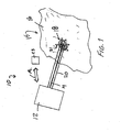
- FIG. 1 provides a side perspective view of one embodiment of a laser ultrasonic detection system 10.
- the detection system 10 comprises a laser ultrasonic unit 12 formed to emit a generation beam 14 and directed to an inspection target 15.
- the generation beam 14. contacts the inspection target 15 on an inspection surface 16.
- the generation beam 14 thermo-elastically expands the inspection surface 16 to produce corresponding wave displacements 18 on the inspection surface 16.
- the generation beam 14 is a pulsed laser configured to produce the ultrasonic displacements 18 on the inspection surface 16.
- a detection beam 20 is also illustrated emanating from the laser ultrasonic unit 12 and is shown coaxial around the generation beam 14. Although emanating from the same laser ultrasonic unit 12, the detection and generation beams (14, 20) are generated by different sources.
- the detection beam 20 may optionally originate from a different unit as well as a different location.
- the detection beam 20 comprises a detection wave that is scattered, reflected, and phase modulated upon contact with the ultrasonic displacements 18 to form phase modulated light 21.
- the phase modulated light 21 from the detection beam 20 is then received by collection optics 23 and processed to determine information about the inspection target 15.
- the generation and detection beams (14, 20) may be scanned across the target 15 to obtain information regarding the entire surface 16.
- a mechanism (not shown) used to scan the beams (14, 20) may be housed within the laser ultrasonic unit 12.
- a processor (not shown) for controlling the mechanism and optionally for processing the data recorded by the collection optics, may also be housed in the laser ultrasonic unit 12.
- the collection optics 23 are shown separate from the laser ultrasonic unit 12 and in communication with the laser ultrasonic unit 12 through the arrow A, however the collection optics may be included with the laser ultrasonic unit 12.
- a generation beam is formed by a laser ultrasound system and directed to the target object to produce thermo-elastic expansions on the surface of the target.
- Ultrasonic displacements are created on the target surface in response to the thermo-elastic expansions. It has been discovered that the amplitude of the ultrasonic displacement, at certain ultrasonic wavelengths, is directly proportional to the optical penetration depth of the generation laser beam into the target surface. The optical penetration depth is the inverse of the optical absorption of the target. Accordingly, by varying the generation laser beam optical wavelength, an absorption band of the target material can be observed over a wavelength range of the generation beam.
- a generation laser beam such as from the laser ultrasonic source 12 of FIG 1 , is directed at a target 15 to create ultrasonic displacements 18 on the target surface 16.
- the amplitudes of the ultrasonic displacements 18 may be measured by the detection laser beam 20 as described above.
- the wavelength of the generation laser beam 14 should be identifiable, that is, the wavelength will be known when producing the surface ultrasonic displacements, can be calculated, or otherwise discerned.
- the target 15 material can be identified by correlating the measured surface displacement 18 with the wavelength of the generation beam 14 used to create the surface displacement 18.
- the values for displacement and wavelength can be compared to previously recorded or otherwise obtained plots or data arrays of corresponding displacement amplitude and generation beam wavelength of known materials.
- the target material and/or composition is determinable.
- a single measurement of displacement amplitude with a corresponding generation beam wavelength is used for identifying a test object material.
- the detection beam wavelength is varied over a spectral range and at discreet points along the range ultrasonic displacements are created in the object.
- the displacement values at each discreet wavelength are measured and correlated to the generation beam wavelength used to create the displacement.
- the measured displacement values and the discreet wavelength values are used to populate a data array of measured values.
- the measured data array can be compared and matched to a data array comprising generation beam wavelengths and corresponding displacements of a known material or materials to thereby identify the target material.
- two measurements of displacement amplitude with a corresponding generation beam wavelength are used for identifying a test object material.
- more than two measurements of displacement amplitude with a corresponding generation beam wavelength are used for identifying a test object material.
- multiple measurements of displacement amplitude with a corresponding generation beam wavelength are used for identifying a test object material, where the spectral range of the generation beam wavelength is from about 0.1 microns to about 20 microns, optionally from about 0.5 microns to about 15 microns, optionally from about 1 micron to about 10 microns, optionally about 2 microns to about 8 microns, optionally about 2.5 microns to about 7.5 microns, and optionally about 3 microns to about 4 microns.
- the increment between successive generation beam wavelengths may be about 0.01 microns or about 3 microns, or any value between.
- successive wavelength values may vary.
- the spectroscopic analysis described herein may be performed on parts that have been manufactured instead of a sample taken from the particular part and analyzed in a laboratory. Additionally, the spectroscopic analysis described herein can also be employed when the part is affixed to a finished product.
- the present method may be used on a finished product during the period of its useful life, i.e. after having been put into service.
- the spectroscopic analysis can occur on an aircraft part during the acceptance testing of the part prior to its assembly on the aircraft.
- a part can be analyzed using the spectroscopic analysis, prior to acceptance of the aircraft, or after the aircraft has been in service and during the life of the part or of the aircraft.
- the present method is not limited to final products comprising aircraft, but can include any product comprising two or more parts.
- the laser ultrasonic system can be used to provide spectroscopic analysis of parts or portions of parts in hard to access locations.
- the present method determines the composition of a target object, such as a manufactured part, the method can determine if the object forming process has been undertaken correctly. For example, if the part is a composite or comprised of a resin product, it can be determined if the composite constituents, such as resin, have been properly processed or cured. Additionally, it can also be determined if a particular or desired constituent, such as resin, was used in forming the final product.
- the analysis can also determine if a coating, such as a painted surface, has been applied to an object, and if the proper coating was applied to the surface and applied properly.
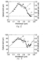
- FIG. 2 illustrates a comparison of optical penetration depth and ultrasonic amplitude displacement (ordinate) versus the optical wavelength (abscissa) of the source used to create the penetration depth and displacement. More specifically, FIG. 2 illustrates a plot 22 reflecting actual data recorded while testing a graphite-epoxy sample.
- the plot 22 comprises a series of points 24 that represent measured amplitudes of ultrasonic displacements of the graphic epoxy sample correlated to the generation beam wavelength that created the ultrasonic displacements.
- the measured optical depth was obtained by a photo acoustic evaluation and it is represented by the line 26.
- the units of measured optical depth and wavelength are both in microns.
- the values of amplitude of the ultrasonic displacements were normalized to clearly illustrate the proportional relationship between the measured amplitude and the optical penetration depth.
- the absolute values are indicative of the displacement response
- the relative shapes of line 26 and of the series of points 24 can be used to identify the material of the target.
- a limited of points can be used for a measurement.
- the ratio of the ultrasonic amplitudes measured at two given wavelengths can be used to either identify the target material or a specific characteristic like the level of curing.
- recorded optical depth data of known composites provides a valid comparison reference to identify a material from measured ultrasonic displacement values and corresponding generation beam wavelength.
- the identification with regard to the material is not limited to the material composition, but can also include coatings, if the material had been properly processed, and percentages of compositions within the materials.
- FIG 3 also illustrates a plot 28 comparing normalized points 30 representing measured amplitude displacements produced by a generation beam and a corresponding line 32 reflecting measured optical depth.
- the material was a graphite-BMI sample.
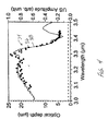
- FIG 4 also compares measured optical depth to normalized amplitude data over a given wave length.
- the object comprises a painted graphite epoxy sample.
- FIGS. 2 - 4 a comparison was presented between a known spectroscopic technique, photoacoustics, and laser ultrasound measurements at 2.5 megahertz.
- the photo acoustic measurements were performed in a laboratory on small samples that were five millimeters in diameter cut from the composite parts.
- the laser ultrasound measurements were performed directly on the composite parts themselves.
- the laser ultrasound measurements were obtained with a laser ultrasound system equipped with an optical parametric oscillator allowing wave length tuning between 3.0 and 3.5 microns. This wavelength range corresponds to the stretching mode of the C-H molecular bond.
- FIGS. 2 - 4 clearly illustrate the proportional relationship between ultrasonic displacement and optical depth in a material, thereby illustrating another advantage of material analysis using the present method.
- the results also show that the laser ultrasound measurements allow easy differentiation between different types of materials.
- a more complete analysis can employ ultrasonic amplitude at several frequencies other than 2.5 MHz, thus the present method is not limited to measurements at 2.5 MHz.
- Another advantage of the present method is a laser ultrasound detection system can perform target spectroscopic analysis while at the same time analyzing the bulk material for the presence of defect conditions and and measuring other general material characteristics such as porosity, foreign materials, delaminations, porosity, foreign materials (inclusions), disbands, cracks, and fiber characteristics such as fiber orientation and fiber density, part thickness, and bulk mechanical properties.
- a more representative spectroscopic analysis is achievable since the analysis is performed on the object itself instead of a test coupon or control sample.
- the scan can be performed on a manufactured part by itself, the part affixed to a larger finished product, or the final finish assembled product as a whole.
- Changing generation beam wavelength can be accomplished in several ways.
- an optical parametric oscillator can be included to provide the ability to change the generation laser wavelength over a range sufficient to carry out the desired chemical identification. If only a limited number of different wavelengths are required, devices like a Raman cell, a Brillouin cell, a multiple wavelength laser, or multiple lasers can be used. Any device or system giving the access to more than one wavelength should be considered as an embodiment of the method disclosed herein.
Landscapes
- Physics & Mathematics (AREA)
- General Health & Medical Sciences (AREA)
- Pathology (AREA)
- Health & Medical Sciences (AREA)
- Life Sciences & Earth Sciences (AREA)
- Chemical & Material Sciences (AREA)
- Analytical Chemistry (AREA)
- Immunology (AREA)
- General Physics & Mathematics (AREA)
- Biochemistry (AREA)
- Signal Processing (AREA)
- Engineering & Computer Science (AREA)
- Acoustics & Sound (AREA)
- Optics & Photonics (AREA)
- Investigating Or Analyzing Materials By The Use Of Ultrasonic Waves (AREA)
- Investigating Or Analysing Materials By Optical Means (AREA)
Applications Claiming Priority (2)
| Application Number | Priority Date | Filing Date | Title |
|---|---|---|---|
| US12/120,907 US8054470B2 (en) | 2008-05-15 | 2008-05-15 | Method and apparatus for spectroscopic characterization of samples using a laser-ultrasound system |
| PCT/US2009/043906 WO2009140468A2 (en) | 2008-05-15 | 2009-05-14 | Method and apparatus for spectroscopic characterization of samples using a laser-ultrasound system |
Publications (2)
| Publication Number | Publication Date |
|---|---|
| EP2286214A2 EP2286214A2 (en) | 2011-02-23 |
| EP2286214B1 true EP2286214B1 (en) | 2015-02-18 |
Family
ID=41258466
Family Applications (1)
| Application Number | Title | Priority Date | Filing Date |
|---|---|---|---|
| EP09747550.3A Not-in-force EP2286214B1 (en) | 2008-05-15 | 2009-05-14 | Method and apparatus for spectroscopic characterization of samples using a laser-ultrasound system |
Country Status (11)
| Country | Link |
|---|---|
| US (1) | US8054470B2 (enExample) |
| EP (1) | EP2286214B1 (enExample) |
| JP (1) | JP5443478B2 (enExample) |
| KR (1) | KR101351231B1 (enExample) |
| CN (1) | CN102089651B (enExample) |
| AU (1) | AU2009246272B2 (enExample) |
| BR (1) | BRPI0912676A2 (enExample) |
| CA (1) | CA2724326C (enExample) |
| IL (1) | IL209292A (enExample) |
| TW (1) | TWI460946B (enExample) |
| WO (1) | WO2009140468A2 (enExample) |
Families Citing this family (8)
| Publication number | Priority date | Publication date | Assignee | Title |
|---|---|---|---|---|
| US8522614B2 (en) * | 2010-05-26 | 2013-09-03 | General Electric Company | In-line inspection methods and closed loop processes for the manufacture of prepregs and/or laminates comprising the same |
| FR2981450B1 (fr) * | 2011-10-17 | 2014-06-06 | Eads Europ Aeronautic Defence | Systeme et procede de controle de la qualite d'un objet |
| CN102506781B (zh) * | 2011-11-17 | 2014-02-12 | 江苏大学 | 一种用于现场检测的激光超声测厚的装置及方法 |
| JP6841609B2 (ja) | 2015-07-10 | 2021-03-10 | 3スキャン インコーポレイテッド | 組織学的染色の空間的多重化 |
| IL243712A0 (en) * | 2016-01-20 | 2016-04-21 | Yeda Res & Dev | Devices and methods for measuring minute fluctuations |
| US11402356B2 (en) * | 2019-12-12 | 2022-08-02 | Provenance Laboratories LLC | Object identification system and method |
| US12306299B2 (en) * | 2021-01-22 | 2025-05-20 | GM Global Technology Operations LLC | LIDAR laser health diagnostic |
| CN113779850B (zh) * | 2021-09-28 | 2025-04-15 | 上海航空工业(集团)有限公司 | 复合材料结构模型的检测方法、检测装置、设备和介质 |
Family Cites Families (7)
| Publication number | Priority date | Publication date | Assignee | Title |
|---|---|---|---|---|
| DK160590C (da) * | 1988-09-12 | 1991-09-16 | Fls Airloq As | Fremgangsmaade til detektering af en gasart ved hjaelp af fotoakustisk spektroskopi |
| US6041020A (en) | 1997-04-21 | 2000-03-21 | University Of Delaware | Gas-coupled laser acoustic detection |
| US6335943B1 (en) * | 1999-07-27 | 2002-01-01 | Lockheed Martin Corporation | System and method for ultrasonic laser testing using a laser source to generate ultrasound having a tunable wavelength |
| US6176135B1 (en) | 1999-07-27 | 2001-01-23 | Marc Dubois | System and method for laser-ultrasonic frequency control using optimal wavelength tuning |
| KR20030015389A (ko) * | 2000-07-14 | 2003-02-20 | 록히드 마틴 코포레이션 | 초음파를 사용하여 복합 재료의 기공도를 결정하는 시스템및 방법 |
| US6378387B1 (en) | 2000-08-25 | 2002-04-30 | Aerobotics, Inc. | Non-destructive inspection, testing and evaluation system for intact aircraft and components and method therefore |
| US6668654B2 (en) * | 2001-08-15 | 2003-12-30 | Lockheed Martin Corporation | Method and apparatus for generating specific frequency response for ultrasound testing |
-
2008
- 2008-05-15 US US12/120,907 patent/US8054470B2/en active Active
-
2009
- 2009-05-14 JP JP2011509689A patent/JP5443478B2/ja not_active Expired - Fee Related
- 2009-05-14 AU AU2009246272A patent/AU2009246272B2/en not_active Ceased
- 2009-05-14 KR KR1020107028048A patent/KR101351231B1/ko not_active Expired - Fee Related
- 2009-05-14 EP EP09747550.3A patent/EP2286214B1/en not_active Not-in-force
- 2009-05-14 CN CN200980125463.8A patent/CN102089651B/zh not_active Expired - Fee Related
- 2009-05-14 BR BRPI0912676A patent/BRPI0912676A2/pt not_active IP Right Cessation
- 2009-05-14 CA CA2724326A patent/CA2724326C/en not_active Expired - Fee Related
- 2009-05-14 WO PCT/US2009/043906 patent/WO2009140468A2/en not_active Ceased
- 2009-05-15 TW TW098116309A patent/TWI460946B/zh not_active IP Right Cessation
-
2010
- 2010-11-14 IL IL209292A patent/IL209292A/en not_active IP Right Cessation
Also Published As
| Publication number | Publication date |
|---|---|
| IL209292A0 (en) | 2011-01-31 |
| US8054470B2 (en) | 2011-11-08 |
| TW200952297A (en) | 2009-12-16 |
| KR101351231B1 (ko) | 2014-01-13 |
| WO2009140468A3 (en) | 2010-01-07 |
| US20090284752A1 (en) | 2009-11-19 |
| BRPI0912676A2 (pt) | 2016-01-26 |
| JP5443478B2 (ja) | 2014-03-19 |
| WO2009140468A2 (en) | 2009-11-19 |
| CN102089651A (zh) | 2011-06-08 |
| KR20110010112A (ko) | 2011-01-31 |
| CN102089651B (zh) | 2014-12-24 |
| JP2011521232A (ja) | 2011-07-21 |
| CA2724326A1 (en) | 2009-11-19 |
| AU2009246272B2 (en) | 2014-01-09 |
| AU2009246272A1 (en) | 2009-11-19 |
| EP2286214A2 (en) | 2011-02-23 |
| CA2724326C (en) | 2014-07-08 |
| TWI460946B (zh) | 2014-11-11 |
| IL209292A (en) | 2013-03-24 |
Similar Documents
| Publication | Publication Date | Title |
|---|---|---|
| EP2286214B1 (en) | Method and apparatus for spectroscopic characterization of samples using a laser-ultrasound system | |
| EP2126559B1 (en) | Method and apparatus for inspecting a workpiece with angularly offset ultrasonic signals | |
| JP3091217B2 (ja) | 複合薄板の非破壊検査方法および装置 | |
| US7010982B2 (en) | Method of ultrasonically inspecting airfoils | |
| EP2703806B1 (en) | Non-destructive evaluation methods for aerospace components | |
| US9074927B2 (en) | Methods for non-destructively evaluating a joined component | |
| US5631423A (en) | Method for resonant measurement | |
| GB2545271A (en) | Determining physical characteristics of a structure | |
| WO2003092128A2 (en) | Method to optimize generation of ultrasound using mathematical modeling for laser ultrasound inspection | |
| Fayazbakhsh et al. | High frequency phased array ultrasonic testing of thermoplastic tensile specimens manufactured by fused filament fabrication with embedded defects | |
| Kaczmarek | Lamb wave interaction with impact-induced damage in aircraft composite: use of the A0 mode excited by air-coupled transducer | |
| Zhong et al. | Ultrasonic testing techniques for nondestructive evaluation of fiber-reinforced composite structures | |
| Grosse et al. | Local Acoustic Resonance Spectroscopy | |
| Stepinski et al. | Narrowband ultrasonic spectroscopy for NDE of layered structures | |
| Jatzlau et al. | Identification of flawed CFRP samples using local acoustic resonance spectroscopy (LARS) | |
| Djordjevic | Laser ultrasonic guided wave methods for defect detection and materials characterisation | |
| GB2700082A (en) | Acoustic inspection method and apparatus therefor | |
| GB2619959A (en) | Acoustic inspection method and apparatus therefor | |
| Bond et al. | Development of Tools for High Volume, High Speed Non-Destructive Inspection of Carbon Fiber Reinforced Plastics (Final Technical Report) | |
| Dubois et al. | Porosity evaluation in aircraft composite parts using laser-ultrasound |
Legal Events
| Date | Code | Title | Description |
|---|---|---|---|
| PUAI | Public reference made under article 153(3) epc to a published international application that has entered the european phase |
Free format text: ORIGINAL CODE: 0009012 |
|
| 17P | Request for examination filed |
Effective date: 20101201 |
|
| AK | Designated contracting states |
Kind code of ref document: A2 Designated state(s): AT BE BG CH CY CZ DE DK EE ES FI FR GB GR HR HU IE IS IT LI LT LU LV MC MK MT NL NO PL PT RO SE SI SK TR |
|
| AX | Request for extension of the european patent |
Extension state: AL BA RS |
|
| 17Q | First examination report despatched |
Effective date: 20110411 |
|
| DAX | Request for extension of the european patent (deleted) | ||
| GRAP | Despatch of communication of intention to grant a patent |
Free format text: ORIGINAL CODE: EPIDOSNIGR1 |
|
| INTG | Intention to grant announced |
Effective date: 20140213 |
|
| GRAP | Despatch of communication of intention to grant a patent |
Free format text: ORIGINAL CODE: EPIDOSNIGR1 |
|
| INTG | Intention to grant announced |
Effective date: 20140827 |
|
| GRAS | Grant fee paid |
Free format text: ORIGINAL CODE: EPIDOSNIGR3 |
|
| GRAA | (expected) grant |
Free format text: ORIGINAL CODE: 0009210 |
|
| AK | Designated contracting states |
Kind code of ref document: B1 Designated state(s): AT BE BG CH CY CZ DE DK EE ES FI FR GB GR HR HU IE IS IT LI LT LU LV MC MK MT NL NO PL PT RO SE SI SK TR |
|
| REG | Reference to a national code |
Ref country code: GB Ref legal event code: FG4D |
|
| REG | Reference to a national code |
Ref country code: CH Ref legal event code: EP |
|
| REG | Reference to a national code |
Ref country code: AT Ref legal event code: REF Ref document number: 710853 Country of ref document: AT Kind code of ref document: T Effective date: 20150315 |
|
| REG | Reference to a national code |
Ref country code: IE Ref legal event code: FG4D |
|
| REG | Reference to a national code |
Ref country code: DE Ref legal event code: R096 Ref document number: 602009029424 Country of ref document: DE Effective date: 20150402 |
|
| REG | Reference to a national code |
Ref country code: NL Ref legal event code: VDEP Effective date: 20150218 |
|
| REG | Reference to a national code |
Ref country code: AT Ref legal event code: MK05 Ref document number: 710853 Country of ref document: AT Kind code of ref document: T Effective date: 20150218 |
|
| REG | Reference to a national code |
Ref country code: LT Ref legal event code: MG4D |
|
| PG25 | Lapsed in a contracting state [announced via postgrant information from national office to epo] |
Ref country code: LT Free format text: LAPSE BECAUSE OF FAILURE TO SUBMIT A TRANSLATION OF THE DESCRIPTION OR TO PAY THE FEE WITHIN THE PRESCRIBED TIME-LIMIT Effective date: 20150218 Ref country code: ES Free format text: LAPSE BECAUSE OF FAILURE TO SUBMIT A TRANSLATION OF THE DESCRIPTION OR TO PAY THE FEE WITHIN THE PRESCRIBED TIME-LIMIT Effective date: 20150218 Ref country code: HR Free format text: LAPSE BECAUSE OF FAILURE TO SUBMIT A TRANSLATION OF THE DESCRIPTION OR TO PAY THE FEE WITHIN THE PRESCRIBED TIME-LIMIT Effective date: 20150218 Ref country code: SE Free format text: LAPSE BECAUSE OF FAILURE TO SUBMIT A TRANSLATION OF THE DESCRIPTION OR TO PAY THE FEE WITHIN THE PRESCRIBED TIME-LIMIT Effective date: 20150218 Ref country code: NO Free format text: LAPSE BECAUSE OF FAILURE TO SUBMIT A TRANSLATION OF THE DESCRIPTION OR TO PAY THE FEE WITHIN THE PRESCRIBED TIME-LIMIT Effective date: 20150518 Ref country code: FI Free format text: LAPSE BECAUSE OF FAILURE TO SUBMIT A TRANSLATION OF THE DESCRIPTION OR TO PAY THE FEE WITHIN THE PRESCRIBED TIME-LIMIT Effective date: 20150218 |
|
| PG25 | Lapsed in a contracting state [announced via postgrant information from national office to epo] |
Ref country code: GR Free format text: LAPSE BECAUSE OF FAILURE TO SUBMIT A TRANSLATION OF THE DESCRIPTION OR TO PAY THE FEE WITHIN THE PRESCRIBED TIME-LIMIT Effective date: 20150519 Ref country code: IS Free format text: LAPSE BECAUSE OF FAILURE TO SUBMIT A TRANSLATION OF THE DESCRIPTION OR TO PAY THE FEE WITHIN THE PRESCRIBED TIME-LIMIT Effective date: 20150618 Ref country code: NL Free format text: LAPSE BECAUSE OF FAILURE TO SUBMIT A TRANSLATION OF THE DESCRIPTION OR TO PAY THE FEE WITHIN THE PRESCRIBED TIME-LIMIT Effective date: 20150218 Ref country code: LV Free format text: LAPSE BECAUSE OF FAILURE TO SUBMIT A TRANSLATION OF THE DESCRIPTION OR TO PAY THE FEE WITHIN THE PRESCRIBED TIME-LIMIT Effective date: 20150218 Ref country code: AT Free format text: LAPSE BECAUSE OF FAILURE TO SUBMIT A TRANSLATION OF THE DESCRIPTION OR TO PAY THE FEE WITHIN THE PRESCRIBED TIME-LIMIT Effective date: 20150218 |
|
| PG25 | Lapsed in a contracting state [announced via postgrant information from national office to epo] |
Ref country code: EE Free format text: LAPSE BECAUSE OF FAILURE TO SUBMIT A TRANSLATION OF THE DESCRIPTION OR TO PAY THE FEE WITHIN THE PRESCRIBED TIME-LIMIT Effective date: 20150218 Ref country code: DK Free format text: LAPSE BECAUSE OF FAILURE TO SUBMIT A TRANSLATION OF THE DESCRIPTION OR TO PAY THE FEE WITHIN THE PRESCRIBED TIME-LIMIT Effective date: 20150218 Ref country code: RO Free format text: LAPSE BECAUSE OF FAILURE TO SUBMIT A TRANSLATION OF THE DESCRIPTION OR TO PAY THE FEE WITHIN THE PRESCRIBED TIME-LIMIT Effective date: 20150218 Ref country code: SK Free format text: LAPSE BECAUSE OF FAILURE TO SUBMIT A TRANSLATION OF THE DESCRIPTION OR TO PAY THE FEE WITHIN THE PRESCRIBED TIME-LIMIT Effective date: 20150218 Ref country code: CZ Free format text: LAPSE BECAUSE OF FAILURE TO SUBMIT A TRANSLATION OF THE DESCRIPTION OR TO PAY THE FEE WITHIN THE PRESCRIBED TIME-LIMIT Effective date: 20150218 |
|
| REG | Reference to a national code |
Ref country code: DE Ref legal event code: R097 Ref document number: 602009029424 Country of ref document: DE |
|
| PG25 | Lapsed in a contracting state [announced via postgrant information from national office to epo] |
Ref country code: PL Free format text: LAPSE BECAUSE OF FAILURE TO SUBMIT A TRANSLATION OF THE DESCRIPTION OR TO PAY THE FEE WITHIN THE PRESCRIBED TIME-LIMIT Effective date: 20150218 |
|
| PLBE | No opposition filed within time limit |
Free format text: ORIGINAL CODE: 0009261 |
|
| STAA | Information on the status of an ep patent application or granted ep patent |
Free format text: STATUS: NO OPPOSITION FILED WITHIN TIME LIMIT |
|
| REG | Reference to a national code |
Ref country code: CH Ref legal event code: PL |
|
| 26N | No opposition filed |
Effective date: 20151119 |
|
| PG25 | Lapsed in a contracting state [announced via postgrant information from national office to epo] |
Ref country code: MC Free format text: LAPSE BECAUSE OF FAILURE TO SUBMIT A TRANSLATION OF THE DESCRIPTION OR TO PAY THE FEE WITHIN THE PRESCRIBED TIME-LIMIT Effective date: 20150218 Ref country code: CH Free format text: LAPSE BECAUSE OF NON-PAYMENT OF DUE FEES Effective date: 20150531 Ref country code: LI Free format text: LAPSE BECAUSE OF NON-PAYMENT OF DUE FEES Effective date: 20150531 Ref country code: LU Free format text: LAPSE BECAUSE OF FAILURE TO SUBMIT A TRANSLATION OF THE DESCRIPTION OR TO PAY THE FEE WITHIN THE PRESCRIBED TIME-LIMIT Effective date: 20150514 |
|
| REG | Reference to a national code |
Ref country code: IE Ref legal event code: MM4A |
|
| PG25 | Lapsed in a contracting state [announced via postgrant information from national office to epo] |
Ref country code: SI Free format text: LAPSE BECAUSE OF FAILURE TO SUBMIT A TRANSLATION OF THE DESCRIPTION OR TO PAY THE FEE WITHIN THE PRESCRIBED TIME-LIMIT Effective date: 20150218 |
|
| PG25 | Lapsed in a contracting state [announced via postgrant information from national office to epo] |
Ref country code: IE Free format text: LAPSE BECAUSE OF NON-PAYMENT OF DUE FEES Effective date: 20150514 |
|
| REG | Reference to a national code |
Ref country code: FR Ref legal event code: PLFP Year of fee payment: 8 |
|
| PG25 | Lapsed in a contracting state [announced via postgrant information from national office to epo] |
Ref country code: BE Free format text: LAPSE BECAUSE OF FAILURE TO SUBMIT A TRANSLATION OF THE DESCRIPTION OR TO PAY THE FEE WITHIN THE PRESCRIBED TIME-LIMIT Effective date: 20150218 |
|
| PGFP | Annual fee paid to national office [announced via postgrant information from national office to epo] |
Ref country code: GB Payment date: 20160527 Year of fee payment: 8 Ref country code: DE Payment date: 20160527 Year of fee payment: 8 |
|
| PGFP | Annual fee paid to national office [announced via postgrant information from national office to epo] |
Ref country code: IT Payment date: 20160520 Year of fee payment: 8 Ref country code: FR Payment date: 20160530 Year of fee payment: 8 |
|
| PG25 | Lapsed in a contracting state [announced via postgrant information from national office to epo] |
Ref country code: MT Free format text: LAPSE BECAUSE OF FAILURE TO SUBMIT A TRANSLATION OF THE DESCRIPTION OR TO PAY THE FEE WITHIN THE PRESCRIBED TIME-LIMIT Effective date: 20150218 |
|
| PG25 | Lapsed in a contracting state [announced via postgrant information from national office to epo] |
Ref country code: HU Free format text: LAPSE BECAUSE OF FAILURE TO SUBMIT A TRANSLATION OF THE DESCRIPTION OR TO PAY THE FEE WITHIN THE PRESCRIBED TIME-LIMIT; INVALID AB INITIO Effective date: 20090514 Ref country code: BG Free format text: LAPSE BECAUSE OF FAILURE TO SUBMIT A TRANSLATION OF THE DESCRIPTION OR TO PAY THE FEE WITHIN THE PRESCRIBED TIME-LIMIT Effective date: 20150218 |
|
| PG25 | Lapsed in a contracting state [announced via postgrant information from national office to epo] |
Ref country code: CY Free format text: LAPSE BECAUSE OF FAILURE TO SUBMIT A TRANSLATION OF THE DESCRIPTION OR TO PAY THE FEE WITHIN THE PRESCRIBED TIME-LIMIT Effective date: 20150218 |
|
| PG25 | Lapsed in a contracting state [announced via postgrant information from national office to epo] |
Ref country code: TR Free format text: LAPSE BECAUSE OF FAILURE TO SUBMIT A TRANSLATION OF THE DESCRIPTION OR TO PAY THE FEE WITHIN THE PRESCRIBED TIME-LIMIT Effective date: 20150218 |
|
| REG | Reference to a national code |
Ref country code: DE Ref legal event code: R119 Ref document number: 602009029424 Country of ref document: DE |
|
| GBPC | Gb: european patent ceased through non-payment of renewal fee |
Effective date: 20170514 |
|
| REG | Reference to a national code |
Ref country code: FR Ref legal event code: ST Effective date: 20180131 |
|
| PG25 | Lapsed in a contracting state [announced via postgrant information from national office to epo] |
Ref country code: DE Free format text: LAPSE BECAUSE OF NON-PAYMENT OF DUE FEES Effective date: 20171201 Ref country code: GB Free format text: LAPSE BECAUSE OF NON-PAYMENT OF DUE FEES Effective date: 20170514 |
|
| PG25 | Lapsed in a contracting state [announced via postgrant information from national office to epo] |
Ref country code: FR Free format text: LAPSE BECAUSE OF NON-PAYMENT OF DUE FEES Effective date: 20170531 Ref country code: IT Free format text: LAPSE BECAUSE OF NON-PAYMENT OF DUE FEES Effective date: 20170514 |
|
| PG25 | Lapsed in a contracting state [announced via postgrant information from national office to epo] |
Ref country code: MK Free format text: LAPSE BECAUSE OF FAILURE TO SUBMIT A TRANSLATION OF THE DESCRIPTION OR TO PAY THE FEE WITHIN THE PRESCRIBED TIME-LIMIT Effective date: 20150218 Ref country code: PT Free format text: LAPSE BECAUSE OF FAILURE TO SUBMIT A TRANSLATION OF THE DESCRIPTION OR TO PAY THE FEE WITHIN THE PRESCRIBED TIME-LIMIT Effective date: 20150218 |